Abstract
To address the complexity of constructing traditional topological contracted graphs due to the significant increase in the types and quantities of basic links during the synthesis of complex parallel mechanisms, this paper introduces a novel concept termed “Simplified Contraction Graph (SCG)”. The SCG achieves a deeper level of simplification by omitting the consideration of ternary links on the basis of traditional contracted graphs. Firstly, this paper defines the application of characteristic strings to express the construction rules of SCG, thereby transforming the construction process into an automated generation problem of characteristic strings. Building on this, to mitigate the interference of link arrangement in the construction of conventional SCGs, this paper further proposes the concept of a simplified SCG and investigates its isomorphism properties. A program is designed based on the criteria for generating characteristic strings and isomorphism judgment, successfully generating several special SCGs. Finally, this paper introduces the edge-adding method, which enables the reconstruction of special SCGs into ordinary SCGs and contracted graphs, providing an effective tool for the topological synthesis of parallel mechanisms.
MSC:
20-08
1. Introduction
Parallel mechanisms are valued for their high stiffness, strong load-bearing capacity, and non-accumulative positioning errors, holding significant application value in manufacturing and other fields, with a broad development prospect [1]. With the continuous growth in market demand for parallel robots, the development of various types of parallel mechanisms has become particularly urgent. Although existing synthesis methods, such as screw theory [2], displacement group theory [3], and linear transformation [4], have significantly advanced the development of parallel mechanisms in recent years, these methods primarily focus on the backend innovation of mechanism design, i.e., the specific types and configurations of components and kinematic pairs. However, when a large number of innovative configurations are needed for designers to choose from, these methods still face significant challenges [5].
In this context, it is especially important to vigorously develop the frontend innovation of design, namely, topological composition innovation. Topological composition defines the composition of the mechanism’s basic links and the connection relationships between them. It is not only the foundation for the realization of the mechanism’s functions but also the key to achieving a large number of fundamental and innovative designs. Mechanisms consist of basic links (defined as i-element links, denoted as Li, based on the number of limbs connected during the construction of the mechanism) and kinematic pairs [6] (such as spherical pairs S and planar pairs E, cylindrical pairs C and universal joints U, and prismatic pairs P, revolute pairs R, and helical pairs H). The types and numbers of basic links are not chosen arbitrarily but are determined based on the mechanism’s degrees of freedom, redundant constraints, and passive degrees of freedom.
To address this, scholars have proposed the concept of Associated Linkage (AL), which refers to a combination of basic links that can be used to construct a mechanism with specified degrees of freedom [7]. Typically, scholars use topological graph (TG) to describe these combinations of basic links for the purpose of topological composition innovation [8]. However, when synthesizing slightly complex parallel mechanisms, the limitations of TGs become apparent. This is because complex mechanisms have a large number of binary links, with complex and variable distribution forms, and many relevant factors need to be considered in the design process, making the analysis and generation of TGs complicated and difficult. To overcome this limitation, scholars have introduced the concept of the contracted graph (CG) [9]. Similar to TG, the CG can also describe the combination of basic links in a mechanism, but its uniqueness lies in the fact that all binary links are ignored. This simplification makes the analysis and generation of the CG more straightforward. Therefore, a CG can be constructed first, and then the number of binary links in the AL can be determined based on the mechanism’s degrees of freedom, redundant constraints, and passive degrees of freedom. Next, combining the requirements of each closed-loop degree of freedom and redundant constraints, the binary links can be distributed to the edges of the CG, thereby constructing the TG [10]. Finally, the TG can be used to synthesize the desired parallel mechanism. The innovative methods based on AL, CG, and TG are collectively referred to as topological composition innovation.
In this context, Tatu synthesized an array of parallel mechanisms using AL [7]. Kim developed static balancers [11] and gravity compensators [12] based on AL. Pozhbelko employed TG to synthesize all possible multi-joint configurations for 1-DOF to 5-loop 12-link mechanisms [13] and established a structural theory addressing the topology, properties, synthesis, and analysis of open, closed, and mixed kinematic chains [14]. Ding synthesized a complete set of planar kinematic chains with up to six independent loops using CG and TG [15] and designed the mechanical arm of a face-shovel hydraulic excavator based on CG, resulting in 364 configuration schemes [16]. Tian proposed a structural synthesis method for coupled sub-chain parallel manipulators based on CG [17] and derived all non-isomorphic CGs for 3T1R generalized parallel mechanisms [18]. Huang automated the synthesis and classification of planar 3-DOF closed-loop mechanism kinematic structures [19] and provided CG and TG synthesis results for Baranov trusses with up to 13 links [20]. Wang introduced a topological search method for enumerating 5-DOF serial chain models of 3-DOF parallel mechanisms [21]. Xia designed crease patterns for origami mechanisms using graph theory, generating all possible CGs for 1-DOF origami mechanisms [22]. Wang proposed a new feature description method for automatic synthesis of CGs from ALs and developed corresponding software [23]. Lu and Ye created numerous novel robot mechanisms through complex ALs [24,25].
Significant progress has been made in the innovation of topological composition for parallel mechanisms. However, recently emerging complex mechanisms, such as spatial grasping devices [26], bionic lower limb exoskeletons [27], deployable grasping serial-parallel manipulators [28], shipborne platforms, and super-large force measuring devices, pose new challenges. A common characteristic of these ultra-complex mechanisms is the substantial increase in the types and numbers of basic links. For instance, the moving table and support seat of a super-large force measuring device requires contact with up to 16 force-measuring points, a demand that exceeds the capability of conventional topological design methods. Consequently, developing new strategies to address these challenges has become an urgent research priority.
Inspired by the concept of CG, this paper introduces a novel concept termed “simplified contracted graphs (SCG)”. This concept builds upon traditional CG methods by further omitting the consideration of ternary links, aiming to alleviate the complexity arising from the significant increase in the types and quantities of basic links through a deeper level of simplification, thereby opening new avenues for topological innovation in complex mechanisms. To enable the automatic generation of SCG, this paper defines an application characteristic string to express the construction rules, thereby transforming the construction problem of SCGs into the construction problem of characteristic strings. Moreover, this paper proposes a method of special SCG combined with edge addition. This method first constructs a special SCG containing only quaternary links and then perfects its structure through the edge addition method. This approach not only eliminates the interference of link arrangement during the construction of SCGs but also facilitates the generation of CGs based on SCGs. This significantly enhances the efficiency of constructing SCGs and CGs and contributes to addressing the challenging issue of graph isomorphism judgment in topological synthesis research [29,30]. Due to the hereditary nature of graphs, adding edges to non-isomorphic SCGs inevitably results in non-isomorphic graphs, thus achieving the discrimination of non-isomorphism at the source.
The paper is organized as follows: Section 2 begins by introducing the concept of SCGs and defines the rules for describing SCGs using characteristic strings. Subsequently, this section further introduces the concept of special SCGs and discusses the process of generating the characteristic strings corresponding to these special SCGs. Section 3 analyzes the types of isomorphism in special SCGs and designs algorithms to generate non-isomorphic SCGs. Section 4 delineates the rules for the application of the edge-adding method and demonstrates its process through concrete examples of topological synthesis. Section 5 is the conclusion.
2. SCG: Concept, Characteristic Strings, and Special One
2.1. Concept of SCG
The SCG proposed in this paper resembles the CG, consisting of a base circle, vertices, and edges. The distinctive feature of the SCG is its inclusion of only quaternary and higher-order basic links. In a SCG, vertices are positioned on the base circle, representing the basic links of the mechanism. The base circle is divided into multiple arcs by the vertices, which along with the edges, define the limb connections between the basic links. Evidently, a vertex representing an i-element link connected to i limbs will be connected to other vertices via i arcs or edges. For instance, Figure 1a) illustrates an SCG for AL (L6 + 4L5 + L4), which comprises one L6, four L5, and one L4 links. Hence, the SCG consists of six vertices. The vertex for L6 is connected to other vertices through two arcs and four edges, each vertex for L5 through five arcs or edges, and the vertex for L4 through two arcs and two edges.
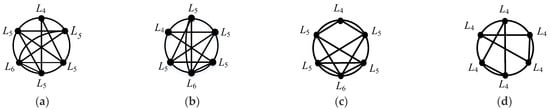
Figure 1.
SCGs. (a) SCG1, L6 + 4L5 + L4; (b) SCG 1’, L6 + 4L5 + L4; (c) SCG 2, L6 + 4L5 + L4; (d) SCG 3, 6L4 (special one).
The construction of SCG can be summarized in three steps: first, establishing a base circle; second, determining the number of vertices based on the composition of basis links with quaternary and higher-order basic links in the AL, and distributing these vertices as evenly as possible along the circumference of the base circle; finally, connecting the vertices with edges according to the rule that the total number of edges and arcs emanating from a vertex representing an i-element link should be i. The manual construction of SCGs is a complex and time-consuming task; hence, the exploration of a more streamlined and scientific construction method is crucial. Building on previous research, this paper proposes the use of characteristic strings to describe SCGs, thereby transforming the graph construction problem into a character construction problem that can be efficiently processed by computers. These characteristic strings accurately capture the features of the SCG, providing an approach for the automated construction of SCGs.
2.2. Characteristic Strings of Describing SCG
The principles for representing SCG using characteristic strings are set as follows:
- (1)
- The Number of Characteristic Strings:
The number of strings is identical to the number of vertices, both equal to k.
The vertex located at the top of the circle, pointing towards the 12 o’clock direction, is defined as 1st vertex. Subsequently, vertices are sequentially recorded as 2nd, and 3rd, in a counterclockwise direction around the base circle, until the kth vertex.
Similarly, the leftmost characteristic string is defined as 1st string, with subsequent strings defined as 2nd, 3rd, …, and kth, from left to right.
That is, the ith string corresponds to and describes the ith vertex.
- (2)
- The Content of Characteristic Strings:
Each string consists of (k − 1) digits, which represent the number of connections between the vertex corresponding to that string and the remaining (k − 1) vertices through arcs or edges.
Specifically, the first digit indicates the number of connections between the vertex and its immediate neighbor in a clockwise direction, the second digit indicates the number of connections between the vertex and its second immediate neighbor in the same direction, …, the (k − 1)th digit represents the number of connections between the vertex and its (k − 1)th immediate neighbor in a clockwise direction.
The process for constructing characteristic strings can be described as follows:
Step 1: Determining the Number of Vertices:
- (1)
- Determine the number of vertices, k, in the SCG.
- (2)
- Establish that the number of characteristic strings will also be k.
Step 2: Labeling Vertices:
- (1)
- Label the vertex at the top of the circle (pointing towards 12 o’clock) as 1st vertex.
- (2)
- Continue labeling the remaining vertices in a counterclockwise direction around the base circle until the kth vertex is reached.
Step 3: Creating Characteristic Strings:
- (1)
- For each vertex, create a characteristic string consisting of (k − 1) digits.
- (2)
- Define 1st characteristic string from left to right as the string for 1st vertex and continue this pattern until the kth string.
Step 4: Filling the Content of Characteristic Strings (For Each Feature String)
- (a)
- The first digit represents the number of connections between the vertex and its immediate clockwise neighboring vertex.
- (b)
- The second digit represents the number of connections between the vertex and the vertex that is the second immediate clockwise neighbor.
- (c)
- Continue this pattern until the (k − 1)th digit, which represents the number of connections between the vertex and the (k − 1)th immediate clockwise neighbor.
According to the proposed principles and process, the characteristic string for the SCG depicted in Figure 1 can be enumerated, as detailed in Table 1. In Table 1, the characteristic string for SCG1 is given by the set {11101, 11111, 10212, 21101, 11111, 10211}. This characteristic string consists of six substrings, each describing one of the six vertices in SCG1 (L4, L5, L6, L5, L5, L5). Each substring comprises five digits, with the 4th substring {21101} representing vertex L5 located at the 6 o’clock position in SCG1. The digits (2, 1, 1, 0, 1) sequentially indicate the number of connections between vertex L5 and its adjacent vertices in the clockwise direction: L6, L5, L4, L5, and L5, respectively.

Table 1.
The 3 characteristic strings for representing 3 SCGs in Figure 1.
It is evident that the characteristic string of each SCG is uniquely determined. The connections between vertices are fixed, hence the strings that describe these connections are also uniquely invariant. Different SCGs exhibit unique connection patterns, resulting in distinct characteristic strings. These strings comprehensively and accurately depict the topological structure of the SCG. No two different SCGs will have the same characteristic string, indicating that the characteristic string provides a complete and unique identifier for the SCG. The characteristic strings describing SCGs also satisfy the following properties:
- (1)
- The digits in the string can only be 0 or positive integers. A digit of 0 indicates the absence of a connection between the corresponding vertices, while a positive integer represents the number of connections.
- (2)
- For the string describing a vertex with an i-element link, the sum of its digits equals i. Since each edge is recorded once in the strings of both its endpoints, the occurrence of identical digits across all characteristic strings is even. Furthermore, half the sum of all digits in the characteristic strings equals the total number of connections between vertices in the SCG.
- (3)
- The characteristic strings exhibit circularity and continuity, such that the first digit of 1st string is identical to the last digit of the kth string. Additionally, the digits at the boundaries of adjacent strings are consistent, meaning the last digit of the jth string matches the first digit of the (j + 1)th string.
- (4)
- The characteristic strings demonstrate symmetry, where the mth digit of the ith string corresponds to the (k − m)th digit of the jth string, reflecting the symmetry of connections between vertices ith and jth.
In the process of constructing unique characteristic strings, the ordering of substrings is a critical factor, which precedes the determination of the string content itself. As illustrated in Table 1, the characteristic strings labeled No.1, No.1’, and No.2 all pertain to the same AL(L6 + 4L5 + L4), the sequence of their substrings varies, yielding L4L5L6L5L5L5 for No.1, L5L4L5L6L5L5 for No.1’, and L4L5L5L6L5L5 for No.2 (their corresponding SCGs are shown in Figure 1a–c). This variation in substring order demonstrates the distinctiveness of each characteristic string. When constructing the characteristic string using AL (which includes ki instances of Li, where ki represents the number of types of Li), the total number of possible arrangements of substrings is (ki)!. Consequently, constructing the SCG through the characteristic string can be complex.
To simplify the construction process of the SCG, this study initially focuses on a special type of SCG that contains only L4 (A 6L4 special one is shown in Figure 1d). Since all vertices are of type L4, there is no need to consider the arrangement of substrings among different types, which simplifies the construction of the characteristic string for this special SCG. For instance, as shown in Table 1, No.3 does not encounter the problem of prioritizing the ordering of substring positions. Based on these special SCGs, other ordinary SCGs can be reconstructed.
Furthermore, the introduction of special SCGs facilitates the subsequent isomorphism judgment of characteristic strings. Due to the hereditary nature of graphs, if there are two non-isomorphic special SCGs (denoted as x and y), any SCG reconstructed from x will not be isomorphic to any SCG reconstructed from y. Therefore, this paper first addresses the characteristic strings of special SCGs and their corresponding graph construction issues.
2.3. Special SCGs and Their Characteristic Strings
This section aims to investigate the construction of characteristic strings for special SCGs containing three to six L4. Since special SCGs are composed exclusively of quaternary links, the ordering of substrings is not a concern in the construction of characteristic strings; instead, the focus is on the content of the substrings. In special SCGs, each L4 vertex is connected to other L4 vertices by four connections, with each connection shared by two L4 vertices. Consequently, the number of connections is twice the number of quaternary links, which forms the mathematical basis for constructing the characteristic strings. The process for generating the characteristic strings is as follows (the equations for solving characteristic strings describing the special SCGs with kL4 are listed in Table 2):
Table 2.
Equations for solving characteristic strings describing the special SCGs with kL4.
- (1)
- Hypothesize unknown quantities: Variables x, y, z, m, and n are defined to represent the number of connections at vertices 1st, 2nd, 3rd, 4th, and 5th, respectively. Based on the principles of setting characteristic strings and in conjunction with Figure 2, the content of the substrings can be determined. The basic characteristic strings for SCGs with three to six L4 are listed in the second column of Table 2. Obviously, the number of unknowns is equal to (k − 1) × k/2 (the variable k represents the number of L4).
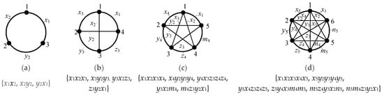 Figure 2. Unknown quantity assumption in special SCGs: (a) 3L4, (b) 4L4, (c) 5L4, (d) 6L4.
 - (2)
- Establish a system of equations: According to the properties (2) of the characteristic strings in Section 2, the sum of the numbers in each substring should be 4, which serves as the basis for establishing k equations.
- (3)
- Resolve the unknowns: Based on steps (1) and (2), the number of free unknowns among the unknown quantities is (k − 3) × k/2. The remaining unknowns can be expressed in terms of these free unknowns, which are referred to as constraint equations. The constraint equations for basic characteristic strings of SCGs with 3 to 6 L4 are shown in the fourth column of Table 2. By prioritizing x variables as the free unknowns and iterating through all possible combinations (as shown in the third column of Table 2), the free unknowns can be obtained. Subsequently, using the constraint equations, all unknowns can be determined, thereby generating a series of characteristic strings. A flow chart of the program for solving characteristic strings is shown in Figure 3.
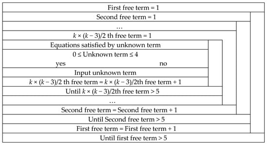 Figure 3. The N-S flow chart of deriving characteristic strings for representing special SCGs with kL4.
However, there are numerous isomorphic phenomena within the characteristic strings. For instance, both No.1 and No. 1’ in Table 1 meet the criteria set forth in Table 2. The SCG1 constructed from No.1 and the SCG1’ constructed from No. 1’ are isomorphic, as illustrated in Figure 1a,b. Identifying these isomorphic characteristic strings to extract effective characteristic strings and subsequently constructing effective special SCGs based on these effective characteristic strings, represents a significant issue worth investigating.
3. Program for Auto-Drawing Special SCGs
This section will commence by delving into the characteristics of isomorphic special SCGs, and on this basis, establish criteria for identifying isomorphic characteristic strings. Subsequently, a program will be developed based on these criteria to filter and eliminate isomorphic characteristic strings, thereby ensuring the extraction of valid characteristic strings. Ultimately, the objective is to utilize these valid characteristic strings to facilitate the automated computer generation of special SCGs.
3.1. Study on the Isomorphism Properties of Special SCGs
Through an analysis of the structural characteristics of special SCGs, three types of isomorphism phenomena have been identified: rotational isomorphism, mirror isomorphism, and mirror isomorphism after rotation. These isomorphism phenomena exhibit the following graphical features: graphs with rotational isomorphism can be transformed into one another through a certain angle of rotation; graphs with mirror isomorphism can be transformed by mirror symmetry along a specific axis; and graphs with mirror isomorphism after rotation undergo a certain angle of rotation followed by a mirror symmetry transformation along a specific axis. Figure 4 illustrates specific examples of these three isomorphism phenomena, and the corresponding characteristic strings are detailed in Table 3.
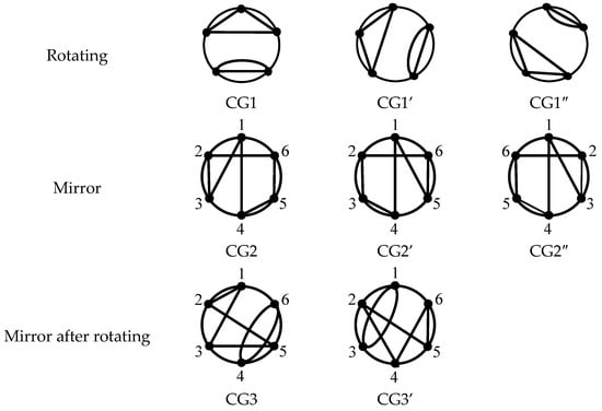
Figure 4.
Three types of isomorphism phenomena for special SCG.
Table 3.
The characteristic string responding to special SCG in Figure 4.
Through the analysis of the characteristic strings of isomorphism special SCGs, the rules for three types of isomorphism have been delineated. For special SCGs with an equivalent number of L4, the following criteria are used to determine isomorphism:
- (1)
- Rotational Isomorphism: If the ith character of the characteristic string x is identical to the jth character of string y, and for all m (1 ≤ m ≤ k − 1), the (i + m)th character of x (with wrapping around to the beginning if it exceeds the range) is the same as the (j + m)th character of y, then x and y are rotationally isomorphic.
- (2)
- Mirror Isomorphism: If the mth bit (1 ≤ m ≤ k − 1) of the ith character in the characteristic string x corresponds to the (k −m)th bit of the ith character in y, then using the ith vertex as a reference point, re-label the vertices of SCG x in a counterclockwise direction and SCG y in a clockwise direction. If the newly labeled characteristic strings x’ and y’ are identical, then x and y are mirror isomorphic.
- (3)
- Rotational and Mirror Isomorphism: If the mth bit (1 ≤ m ≤ k − 1) of the ith character in the characteristic string x corresponds to the (k − m)th bit of the jth character in y, then label the vertices of SCG x starting from the ith vertex in a counterclockwise direction and SCG y from the jth vertex in a clockwise direction. If the resulting characteristic strings x’ and y’ are consistent, then x and y are rotationally and mirror isomorphic.
A valid special characteristic string is characterized by adherence to the established criteria, while explicitly excluding strings that demonstrate the predefined isomorphic properties. An SCG that is expressed by the valid special characteristic string is termed a valid SCG.
3.2. Program for Identifying Valid Characteristic Strings and Automating the Drawing of Special SCGs
The program flow diagram, based on the criteria established in Section 4.1, for filtering and eliminating isomorphic feature strings, retaining valid feature strings, and automatically generating special SCGs is presented in Figure 5.
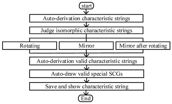
Figure 5.
A program flow diagram for solving valid characteristic strings and auto-draw special SCGs.
The program is structured around three primary modules to fulfill the design objectives:
- Characteristic String Generation Module: This module generates characteristic strings that conform to the specified mathematical relationships based on the number of L4.
- Isomorphism Characteristic String Judgment Module: This module screens the basic characteristic strings produced by the previous module, automatically filters and eliminates isomorphic strings, and extracts valid characteristic strings.
- Special SCG Drawing Module: This module automates the drawing of special SCGs using the selected valid characteristic strings.
The software interfaces include one for the automatic generation of characteristic strings and another for the automatic drawing of special SCGs. Figure 6 illustrates the interface for automatic generation, which consists of a form and two frames. One frame houses a label, a text box, and button controls. The label and text box display information about the number of L4 for the characteristic strings to be generated. Five buttons, labeled “Basic Feature Array”, “Delete Rotational Isomorphism”, “Delete Mirror Isomorphism”, “Delete Rotational and Mirror Isomorphism”, and “Auto-Draw Special SCG”, control the generation of basic strings, the deletion of isomorphisms, and access to the auto-drawing interface. For instance, entering “5” in the text box and clicking “Basic Feature Array” displays the basic feature arrays for a special SCG with 5L4 in the list box (Figure 6). Subsequent clicks on the isomorphism deletion buttons will display valid characteristic strings. Clicking “Auto-Draw Special SCG” transitions to the main drawing interface.
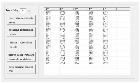
Figure 6.
The software interfaces of automatic generation valid characteristic string.
3.3. Program-Assisted Derivation of Special SCGs
A total of 4/6 valid characteristic strings with 4L4/5L4 are derived, as shown in Table 4. Next, 4/6 valid special SCGs with 4L4/5L4 are auto-drawn by characteristic strings based on the program, as shown in Figure 7.
Table 4.
The valid characteristic strings with 4L4/5L4.
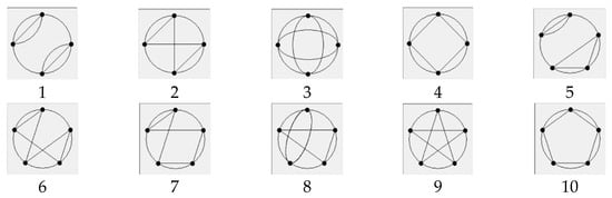
Figure 7.
Special SCGs with 4L4 (1–4) and 5L4 (5–10).
Twenty-seven valid characteristic strings with 6L4 are derived, as shown in Table 5. Next, 27 valid special SCGs with 6L4 are auto-drawn by characteristic strings based on the program, as shown in Figure 8.
Table 5.
The valid characteristic strings with 6L4.
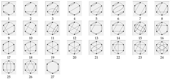
Figure 8.
Special SCGs with 6L4.
4. Reconstruction Using Special SCGs and Application Examples
4.1. Edge Addition Method
To reconstruct conventional SCGs with different types and quantities of Li, this section proposes an edge addition method based on special SCGs. The method encompasses the following three strategies for adding edges:
- (1)
- Vertex-to-Vertex: This strategy involves connecting two distinct vertices to increase the number of connections in the graph. After each operation, the number of connections in the new SCG increases by one, and the corresponding link element count for the two vertices involved in the edge addition each increases by one.
- (2)
- Vertex-to-Edge: In this strategy, a vertex is connected to an existing edge, effectively dividing the original edge into two new edges. This operation results in an increase of one in both the number of vertices and connections of the graph, which corresponds to the addition of a ternary link, while the link element counts for the vertex involved in the edge addition also increases by one.
- (3)
- Edge-to-Edge: This method involves connecting two non-intersecting edges, thereby introducing two new vertices. This results in an increase of one in the number of edges and an increase of two in the number of vertices, corresponding to the addition of two ternary links.
Utilizing these strategies, conventional SCGs/CGs with diverse structures and attributes can be effectively constructed on the basis of special SCGs. For instance, by employing the vertex-to-vertex, vertex-to-edge, and edge-to-edge addition methods, the special SCG1 depicted in Figure 7 can be reconstructed into graphs containing 2L5 + 2L4, L5 + 3L4 + L3, and 4L4 + 2L3, as shown in Table 6.
Table 6.
The compare with common and special SCGs by the edge addition method.
Additionally, leveraging the hereditary nature of graphs, the edge addition method effectively bypasses the need for redundant isomorphism checks. For instance, Figure 9 illustrates two distinct special SCGs (SCG1 and SCG4), both incorporating a 4L4 structure. Applying the three edge-adding strategies to these graphs results in distinct structures as follows:
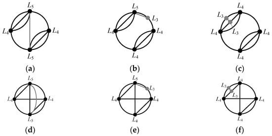
Figure 9.
The example of adding edges. (a) Vertex-to-vertex addition on SCG in Figure 7 (1); (b) Vertex-to- edge addition on SCG in Figure 7 (1); (c) Edge-to-edge addition on SCG in Figure 7 (1); (d) Vertex-to-vertex addition on SCG in Figure 7 (4); (e) Vertex-to- edge addition on SCG in Figure 7 (4); (f) Edge-to-edge addition on SCG in Figure 7 (4).
Clearly, the reconstructed SCGs/CGs are mutually non-isomorphic. Hence, it is evident that a variety of different SCGs/CGs can be reconstructed based on special SCGs.
4.2. Examples of Type Synthesis
Based on special SCGs, a variety of CGs or SCGs with distinct AL can be reconstructed, enabling the synthesis of numerous novel complex mechanisms. The following examples illustrate the synthesis of several mechanisms:
Example 1: An edge-to-edge connection is added to the special SCG with 2L4, resulting in the reconstruction of a CG with 2L4 + 2L3. A digital TG with 2L4 + 2L3 + 19L2 and M = 5, ν = 3 [10] is derived from CG1 in Figure 10a. This leads to the synthesis of a 5-DoF parallel mechanism incorporating one parallel module and one plane mechanism, as shown in Figure 10a (Example 1 and Example 2). In Figure 10, R stands for revolute joint, P for prismatic joint, S for spherical joint, and U for universal joint. In Example 1, the connection between the moving and basic platforms is connected through four limbs. Three of these limbs are identical SPR chains, while the remaining limb comprises a complex planar sub-chain, specifically in the form of RU(2RPR)RR. Here, (2RPR) denotes a planar sub-chain. In Example 2, the connection between the moving and basic platforms is also realized by four limbs. However, in this case, three limbs are of the UPU configuration, while the remaining limb maintains the same RU(2RPR)RR structure as seen in Example 1.
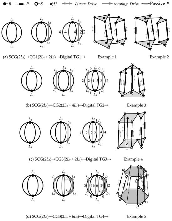
Figure 10.
Examples of type synthesis.
Example 2: Two edge-to-edge connections are added to the special SCG with 2L4, reconstructing a CG with 2L4 + 4L3. A digital TG with 2L4 + 4L3 + 19L2 and M = 5, ν = 6 [10] is derived from CG2 in Figure 10b. This synthesis yields a 5-DoF parallel mechanism with one central passive constrained limb and two plane mechanisms, as shown in Figure 10 (Example 3). In parallel mechanism 3, the connection between the moving and basic platforms is established by four actuated limbs and one passive limb. The passive limb is of the UPU configuration. Among the actuated limbs, one is a simple SPU chain, while the other two comprise complex structures that include a planar sub-chain, specifically in the form of U(2RPR)R.
Example 3: Edge-to-edge and vertex-to-vertex connections are added to the special SCG with 2L4, reconstructing a CG with 2L5 + 2L3. A digital TG with 2L5 + 2L3 + 28L2 and M = 6 [10] is derived from CG3 in Figure 10c. This results in the synthesis of a 6-DoF parallel mechanism with one central constrained limb is synthesized, as shown in Figure 10c (Example 4). Example 4 consists of five limbs that enable the realization of 6-DOF. Among these five limbs, there are three SPUs, one UPR, and one U(2SPR)U, where (2SPR) denotes a spatial sub-chain.
Example 4: Three edge-to-edge and two vertex-to-vertex connections are added to the special SCG with 2L4, reconstructing a CG with 2L6 + 6L3. A digital TG with 2L6 + 6L3 + 33L2 and M = 6, ν = 9, ζ = 3 [10] is derived from CG4 in Figure 10d. This synthesis produces a 6-DoF parallel mechanism with three passive constrained limbs and three plane mechanisms, as shown in Figure 10d (Example 5). In Example 5, the configuration includes two types of limbs, summing up to six, which are interwoven and uniformly distributed between the moving and basic platforms. One type consists of passive SPS chains, while the other type comprises active R(2RPR)RR chains, with (2RPR) denoting an active planar sub-chain.
The degrees of freedom (DoF) for the parallel mechanisms 1–5 synthesized in Figure 10 have been verified using the modified Kutzbach–Grübler formula [17] and are summarized in Table 7.
Table 7.
DoF verifications of parallel mechanisms 1–5 synthesized in Figure 10.
5. Conclusions
The paper introduces the concept of SCGs and the rules for their characteristic strings, successfully providing a simplified approach for the topological synthesis of complex parallel mechanisms. By introducing the concept of special SCGs, we have streamlined the automatic generation process, making the creation of specific SCG configurations more efficient. Moreover, the proposed edge-adding method further facilitates the generation of topological graphs based on special SCGs, rendering them suitable for type synthesis.
These findings offer theoretical tools and practical solutions for the field of parallel mechanism topology design, greatly aiding engineers and researchers in the original innovation of new types of parallel mechanisms. Future research will explore the automation of the edge-adding method to achieve full computerization of the topological synthesis process.
Author Contributions
Conceptualization, N.Y.; methodology, N.Y.; software, N.Y. and Z.G.; validation, N.Y. and Z.G.; data curation, Z.G.; writing—original draft preparation, N.Y. and Z.G.; writing—review and editing, N.Y. and Z.G.; funding acquisition, N.Y. All authors have read and agreed to the published version of the manuscript.
Funding
This research was funded by the National Natural Science Youth Foundation of China (52205033), and the Hebei Provincial Natural Science Foundation (No. E2021203019).
Data Availability Statement
Data are provided within the manuscript.
Conflicts of Interest
The authors declare no conflict of interest.
References
- Russo, M.; Zhang, D.; Liu, X.J.; Xie, Z.H. A review of parallel kinematic machine tools: Design, modeling, and applications. Int. J. Mach. Tools Manuf. 2024, 196, 104118. [Google Scholar] [CrossRef]
- Huang, Z.; Zhao, Y.S.; Zhao, T.S. Advanced Spatical Mechanism; Higher Education Press: Beijing, China, 2006. [Google Scholar]
- Lee, C.C.; Hervém, J.M. Type synthesis of primitive Schoenflies-motion generators. Mech. Mach. Theory 2009, 44, 1980–1997. [Google Scholar] [CrossRef]
- Gogu, G. Structural synthesis of fully-isotropic parallel robots with Schonflies motions via theory of linear transformations and evolutionary morphology. J. Mech. A/Solids 2007, 26, 242–269. [Google Scholar] [CrossRef]
- Ke, T.; Ding, H.F.; Kecskemethy, A. Automatic synthesis method for multi-speed automatic transmission configuration. Mech. Mach. Theory 2025, 205, 105864. [Google Scholar] [CrossRef]
- Zhao, J.S.; Zhou, K.; Feng, Z.J. A theory of degrees of freedom for mechanisms. Mech. Mach. Theory 2004, 39, 621–643. [Google Scholar] [CrossRef]
- Johnson, R. Mechanical Design Synthesis: Creative Design and Optimization, 2nd ed.; Huntington: New York, NY, USA, 1978; pp. 19–114. [Google Scholar]
- Sohn, W.J.; Freudenstein, F. An Application of Dual Graphs to the Automatic Generation of the Kinematic Structures of Mechanisms. Am. Soc. Mech. Eng. 1986, 108, 392–398. [Google Scholar]
- Hsu, C.H.; Yan, H.S. Structural Synthesis of Contracted Graphs. J. Chin. Soc. Mech. Eng. 1986, 7, 125–135. [Google Scholar]
- Lu, Y.; Leinonen, T. Type synthesis of unified planar–spatial mechanisms by systematic linkage and topology matrix-graph technique. Mech. Mach. Theory 2005, 40, 145–1163. [Google Scholar] [CrossRef]
- Kim, S.H.; Cho, C.H. Design of planar static balancer with associated linkage. Mech. Mach. Theory 2014, 81, 79–93. [Google Scholar] [CrossRef]
- Kim, S.H.; Cho, C.H. Design of gravity compensators using the Stephenson and Watt mechanisms. Mech. Mach. Theory 2016, 102, 68–85. [Google Scholar] [CrossRef]
- Pozhbelko, V.; Ermoshina, E. Number structural synthesis and enumeration process of all possible sets of multiple joints for 1-DOF up to 5-loop 12-link mechanisms on base of new mobility equation. Mech. Mach. Theory 2015, 90, 108–127. [Google Scholar] [CrossRef]
- Pozhbelko, V. A unified structure theory of multibody open-, closed-, and mixed-loop mechanical systems with simple and multiple joint kinematic chains. Mech. Mach. Theory 2016, 100, 1–16. [Google Scholar] [CrossRef]
- Ding, H.F.; Huang, P.; Yang, W.J.; Kecskemethy, A. Automatic generation of the complete set of planar kinematic chains with up to six independent loops and up to 19 links. Mech. Mach. Theory 2016, 96, 75–93. [Google Scholar] [CrossRef]
- Ding, J.S.; Li, X.X.; Ding, H.F.; Yang, W.J. Computer aided synthesis method for the configuration of the mechanical arm of face-shovel hydraulic excavator based on contracted graph and open loop kinematic chains. Mech. Mach. Theory 2024, 197, 105627. [Google Scholar] [CrossRef]
- Tian, C.X.; Fang, Y.F.; Ge, Q.D. Structural synthesis of parallel manipulators with coupling sub-chains. Mech. Mach. Theory 2017, 118, 84–99. [Google Scholar] [CrossRef]
- Tian, C.X.; Fang, Y.F.; Ge, Q.D. Design and analysis of a partially decoupled generalized parallel manipulator for 3T1R motion. Mech. Mach. Theory 2019, 140, 211–232. [Google Scholar] [CrossRef]
- Ding, H.F.; Huang, P.; Liu, J.F.; Kecskemethy, A. Automatic structural synthesis of the whole family of planar 3-Degrees of freedom closed loop mechanisms. J. Mech. Robot. 2013, 5, 041006. [Google Scholar] [CrossRef]
- Huang, P.; Ding, H.F. Structural synthesis of baranov trusses with up to 13 links. J. Mech. Des. 2019, 141, 072301. [Google Scholar] [CrossRef]
- Wang, M.F.; Ceccarelli, M. Topology Search of 3-DOF Translational Parallel Manipulators with Three Identical Limbs for Leg Mechanisms. Chin. J. Mech. Eng. 2015, 18, 666–675. [Google Scholar] [CrossRef]
- Xia, Z.H.; Tian, C.X.; Li, L.Q.; Zhang, D. The novel synthesis of origami-inspired mechanisms based on graph theory. Mech. Mach. Theory 2024, 192, 105547. [Google Scholar] [CrossRef]
- Wang, Y.; Chen, S.; Chen, Z.P. Feature description method for contracted graphs of kinematic chains and automatic synthesis by CAD. Symmetry 2023, 15, 1559. [Google Scholar] [CrossRef]
- Lu, Y.; Ye, N.J.; Zhang, L.J. Unified recursive derivation and analysis of complex associated linkages with various links and type synthesis of complex robot mechanisms. J. Braz. Soc. Mech. Sci. 2017, 39, 4091–4106. [Google Scholar] [CrossRef]
- Lu, Y.; Ye, N.J. Type synthesis of parallel mechanisms by utilizing sub-mechanisms and digital topological graphs. Mech. Mach. Theory 2017, 109, 39–50. [Google Scholar] [CrossRef]
- Wang, R.; Song, Y.; Dai, J.S. Reconfigurability of the origami-inspired integrated 8R kinematotropic metamorphic mechanism and its evolved 6R and 4R Mechanisms. Mech. Mach. Theory 2021, 161, 104245. [Google Scholar] [CrossRef]
- Ren, B.; Liu, J.W.; Luo, X.R.; Chen, J.Y. On the kinematic design of anthropomorphic lower limb exoskeletons and their matching. Int. J. Adv. Robot. Syst. 2019, 16, 1729881419875908. [Google Scholar] [CrossRef]
- Li, G.T.; Huang, H.L.; Guo, H.W.; Li, B. Design, analysis and control of a novel deployable grasping manipulator. Mech. Mach. Theory 2019, 138, 182–204. [Google Scholar] [CrossRef]
- Ye, Z.Z.; Huang, X.W.; Wu, C.Y.; Xue, X.L.; Sun, L. Synthesis of contracted graph for planar nonfractionated simple-jointed kinematic chain based on similarity information. Mech. Mach. Theory 2023, 181, 105227. [Google Scholar] [CrossRef]
- Yu, L.C.; Wang, H.B.; Zhou, S.Q. Graph isomorphism identification based on link-assortment adjacency matrix. Sādhanā 2022, 47, 151. [Google Scholar] [CrossRef]
Disclaimer/Publisher’s Note: The statements, opinions and data contained in all publications are solely those of the individual author(s) and contributor(s) and not of MDPI and/or the editor(s). MDPI and/or the editor(s) disclaim responsibility for any injury to people or property resulting from any ideas, methods, instructions or products referred to in the content. |
© 2025 by the authors. Licensee MDPI, Basel, Switzerland. This article is an open access article distributed under the terms and conditions of the Creative Commons Attribution (CC BY) license (https://creativecommons.org/licenses/by/4.0/).