1. Introduction
In recent years, the demand for modeling and analysis of enhanced mechanical structures has significantly increased in various mechanical engineering applications [
1,
2]. Materials with a high strength-to-weight ratio, which are utilized in sandwich structures, have become increasingly prevalent due to their superior mechanical properties, including high stiffness, strength, and fatigue resistance [
3,
4,
5,
6]. One of the most promising designs in this category is the honeycomb sandwich panel, which consists of two stiff face sheets separated by a low-density core. The unique combination of properties allows honeycomb structures to excel in applications that require optimized weight reduction without compromising structural integrity. Furthermore, these structures, traditionally used for their load-bearing capacity, are now being explored for multifunctional uses. As highlighted by previous studies [
7,
8], sandwich structures with a honeycomb core have been widely used in aerospace application due to their excellent properties.
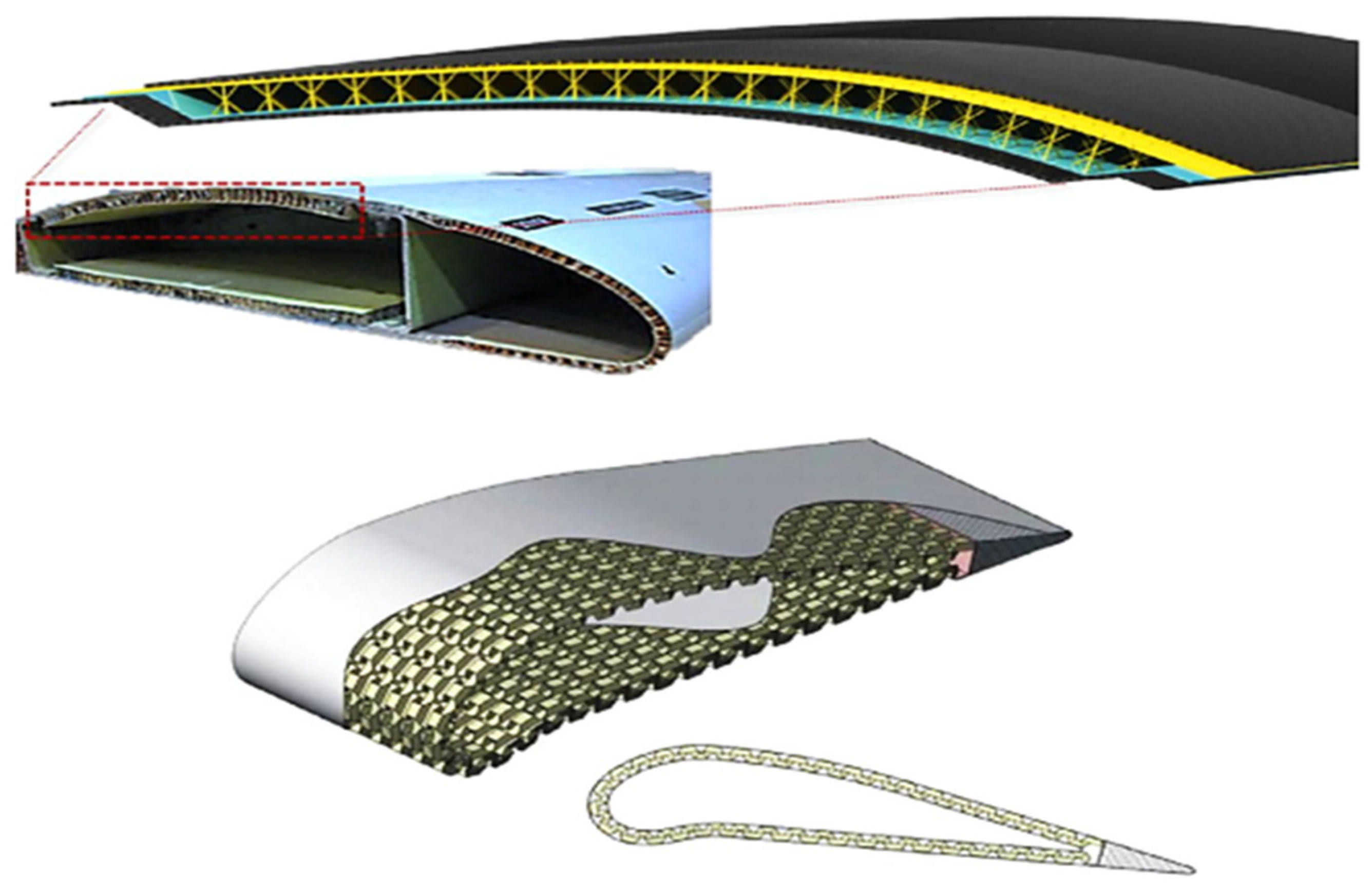
Figure 1 illustrates the titanium Kagome core solution proposed by Ullah et al., which outperforms traditional honeycomb cores in terms of shear strength and compression. Such innovative cores, including Kagome, folded, and corrugated designs, provide enhanced structural integrity and offer viable alternatives to commonly used Nomex or aluminum honeycombs, particularly for applications like ailerons [
9,
10,
11].
Numerous studies have investigated the vibrational behavior of honeycomb sandwich structures, particularly focusing on free vibration modes. Sakar [
11] conducted both numerical and experimental analyses on aluminum honeycomb beams, focusing on the dynamic behavior under modal analysis techniques. The results demonstrated the effects of design parameters, such as core thickness and support conditions, on the natural frequencies and vibration modes. Similarly, Harish et al. [
12] explored the influence of core height on the stiffness and fundamental natural frequency of sandwich panels, demonstrating that increasing the core height leads to an enhanced moment of inertia, which improves the structure’s stiffness.
Further research by Naresh et al. [
13] focused on the impact of different honeycomb core geometries and materials on vibration characteristics. Their work utilized numerical modeling techniques, employing the finite element method (FEM) to assess the effects of core shape and material properties on natural frequency. Additionally, Jweeg [
14] provided an analytical approach to calculating natural frequencies of honeycomb sandwich panels, considering honeycomb design factors like cell size and core height, further concluding that the stiffness and natural frequency increase with larger cell dimensions. For instance,
Figure 2 showcases the growing trend of multifunctionality in sandwich structures.
Figure 2a explores the integration of solar cells into the working skins of sandwich structures, as part of the Solar Impulse project, allowing the panels to fulfill both energy-harvesting and structural roles [
10]. On the other hand,
Figure 2b shows a sandwich structure, which is designed for boundary layer suction in a glider, enhancing its aerodynamic performance. These multifunctional approaches demonstrate how sandwich panels are evolving to meet diverse operational needs beyond their mechanical properties [
10].
A thorough review of the literature revealed a noticeable lack of studies specifically addressing the forced vibration behavior of sandwich structures under transient loading conditions. This gap highlights the importance of the present study in providing new insights into this critical aspect, particularly for aerospace applications. Therefore, this study aims to fill this gap by providing a theoretical and analytical investigation into the forced vibration behavior of aircraft sandwich panels with a honeycomb core under transient loading conditions. The core design parameters, such as cell size, core height, and wall thickness, are systematically studied using both analytical solutions and numerical models based on finite element techniques.
2. Methodology
Sandwich panels with a honeycomb core are widely used in various engineering applications, particularly in aircraft structures, where they are subjected to multiple types of loads. Among these, transient loads have a significant impact on the dynamic performance of such structures. Therefore, understanding the behavior of these panels under transient loading conditions is essential to ensure structural integrity and optimize design accuracy.
In this study, a mathematical model was derived based on the small deflection theory of thin plates through several stages, which are detailed in the following section. Subsequently, a numerical simulation was performed using ANSYS 19.2 to analyze the dynamic response of the structure under transient loading.
To validate the accuracy of the mathematical model and numerical simulation, the theoretical results were compared with those obtained from ANSYS. The comparison demonstrated a 95% agreement, confirming the reliability of the proposed model. These results and their analysis are presented in
Section 5.
3. Analytical Solution
In this study, the analytical solution is based on the small deflection theory of plates, assuming linear elasticity and small deformations. Damping effects are neglected due to the nature of the applied loads and the expected material response. The analysis can be divided into three sequential stages:
The first step involves deriving the differential equation of motion that governs the forced vibration behavior of the sandwich structure under transient load. This equation accounts for the dynamic forces acting on the structure, including the external transient load, the structural stiffness, and the damping effects present in the system [
15].
- B.
Solution for Free Vibration
After deriving the equation of motion, the system’s free vibration response is evaluated. The natural frequencies of the sandwich structure are determined by solving the differential equation in the absence of external forces. These frequencies are critical as they define the inherent vibrational characteristics of the structure, which play a crucial role in its dynamic response to external excitations [
16,
17].
- C.
Solution for forced vibration under transient loading
The final step addresses the forced vibration response under transient loading conditions. The transient response of the system is evaluated by solving the governing equation with the applied transient force. This solution provides key insights into the system’s maximum amplitude and transient response. These parameters help in understanding how the structure behaves under practical loading conditions, allowing a more accurate prediction of its dynamic performance and stability.
Each stage of this analytical solution is essential for evaluating the vibrational behavior of the sandwich structure with a honeycomb core. The integration of these steps provides a robust framework for analyzing both free and forced vibrations, ultimately leading to a clearer understanding of the transient response characteristics [
18].
3.1. Differential Equation of Motion of Sandwich Structure with Honeycomb Core
Depending on the small deflection theory of thin plates, the differential equation of motion of the plate is [
19,
20]
where
,
,
, and
are given by
where
,
, and
are the normal stress and share stress acting on the plate [
19,
20]:
In this research, all the symbols are defined in the nomenclature list. The parameters Exx, Eyy, Gxy, vxy, and vyx are the mechanical properties of the plate material parts in the x and y directions. The deflection of the plate occurs in the z-direction.
The application of (2) and (3) to each layer of sandwich panels (upper face, core, and lower face) is illustrated in
Figure 3 to derive the governing differential equation of motion of sandwich panels with a honeycomb core.
3.1.1. Upper Face
Since aluminum, which this study views as a homogenous material, makes up the upper face, the elastic constants are as follows:
Substituting (4) into (3) gives
The expressions in (5) represent the normal stress and shear stress in the upper face of the sandwich structure. To evaluate the bending moments and twisting moments, substituting (5) into (2) with integration limits (from
to
) gives
The equations in (6) represent the direct bending moment in the (x, y) direction and the twist moment of the upper plate of the sandwich panels.
3.1.2. Honeycomb Core
Knowledge of the effective elastic moduli of honeycomb cores used for sandwich structures is essential for their design. In particular, the properties of honeycomb cores are crucial for describing the behavior of sandwich constructors [
21]. Various models exist to predict the equivalent elastic constants of the honeycomb core structure, also known as the nine constants. Researchers such as Master and Evan, E. Nast, Qunliliu, Ashby, and Grediac evaluate these constants using different relations.
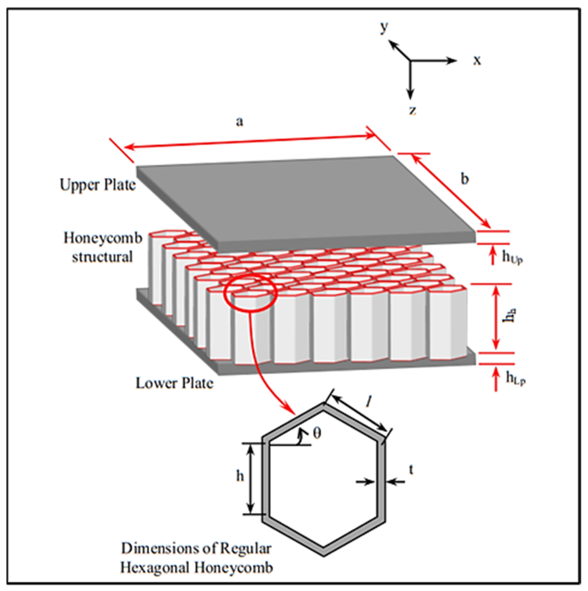
Figure 4 shows a regular unit cell with a hexagonal honeycomb structure, where (
θ) is cell angle, (
t) is wall thickness, (
l) is incline wall length, (a) is vertical wall length, and (2
lcos
θ) is cell size. For a regular honeycomb core, the cell angle is equal to 300, the wall thickness is constant, and (
l = a).
Since the E. Nast model calculates all the elastic constants, it is the most suitable model for the theoretical analysis. The aluminum honeycomb, which is considered an orthotropic material, forms the core layer. Consequently, the following elastic constants apply:
Substituting (7) into (3) results in
The equations in (8) represent the normal and shear stress in the core layer of the sandwich structure. To evaluate the bending moments and twisting moments, substituting (8) into (2) with integration limits (from
to
) yields
The equations in (9) represent the direct bending moment in the (x, y) direction and the twist moment of the honeycomb core layer of the sandwich panels.
3.1.3. Lower Face
In this study, the lower face is made from aluminum, which is considered a homogenous material; therefore, the elastic constants are
Substituting (10) into (3) gives
The equations in (11) represent the normal stress and shear stress in the lower face of the sandwich structure.
To evaluate the bending moments and twisting moments, by substituting (11) into (2) with integration limits (from
to
), as shown in
Figure 3, one obtains the following:
The equations in (12) represent the direct bending moment in the (
x,
y) direction and the twist moment of the upper plate of the sandwich panels. Equation (1) requires the substitution of (6), (9), and (12) to obtain the governing differential equation of motion for sandwich panels with honeycomb core:
where
and
are defined as
3.2. Free Vibration Analysis of Sandwich with Honeycomb Core
Free vibration occurs when a system oscillates solely due to an initial disturbance, without any external forces acting thereafter to achieve this purpose. If the term
in (13) is set to zero, then
The expression given in (14) is a nonhomogeneous governing differential equation of the free vibration of a honeycomb sandwich. The separation variables method is used to solve (14) by assuming the deflection shape [
22].
where
Deflection function of sandwich with respect to time;
Deflection function of sandwich in x and y directions for simple supported sandwich plate.
Substituting (16) into (15) results in
Now, if (17) is substituted into (14), one obtains the following:
It can be seen that (18) is a second-order ordinary differential equation. On the other hand, the ordinary differential equation of a single-degree-of-freedom system is
. The natural frequency formula can be expressed as follows:
where
is the natural frequency of the rectangular sandwich panel with a honeycomb core.
3.3. Forced Vibration of Sandwich Structure Under Transient Force
A mechanical or structural system is said to undergo forced vibration whenever external energy is supplied to the system during vibration. An applied force excitation can supply external energy to the system. This study subjects the system to a suddenly applied nonperiodic force, resulting in a transient vibration response [
16,
17]. Recalling Equation (13), it can be rearranged to represent the partial differential equation of motion of the forced vibration of the honeycomb sandwich panel:
where
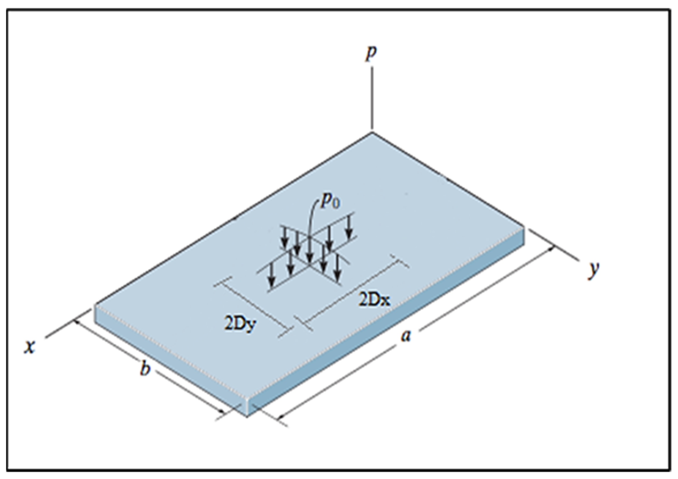
Using the separation of variables method (see (17)) and the orthogonality principle to solve (20), we obtain
where
, and
is the distributed force over element (2
Dx 2
Dy), as shown in
Figure 5, which is defined as
So, the right-hand side of (21) is equal to
For the first mode,
m =
n = 1 and
. Hence, reassembling (21) gives
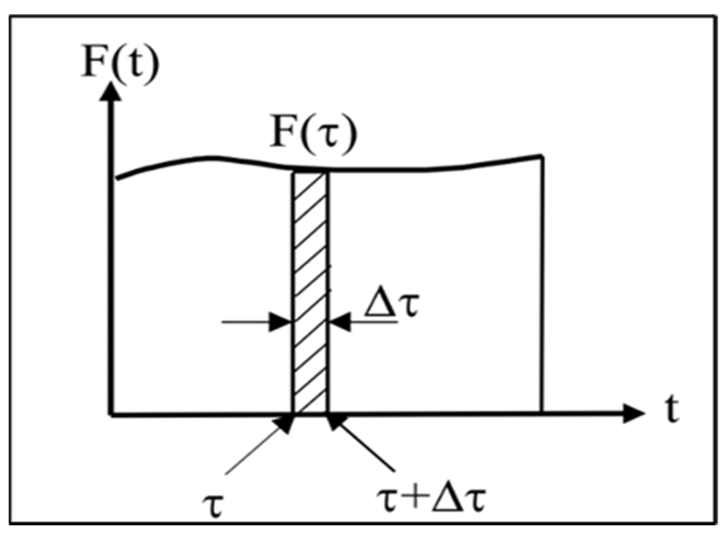
Equation (22) falls under the category of a second-order ordinary differential equation. The solution depends on the natural exaction force that causes the forced vibration. In the current study, the transient load is applied to honeycomb sandwiches within a brief timeframe.
Figure 6 shows the schematic of the transient force.
Assuming that at
the force
(
) acts on the system for a short period of time Δ
, the impulse acting at
is given by
(
) × Δ
. At any time
, the elapsed time since the impulse is
. Hence, the system response at
due to this impulse alone is given by [
23]
where
is the damping frequency,
is the damping ratio, and
is the natural frequency. In addition, we have
Substituting (24) into (23) yields
In this study, the system is affected by a transient force during the period (0–0.0002) s, following which the response decays.
- ➢
For t = 0–0.0002 s
Let
Therefore, the total system response to a transient load over a period of time (0–0.0002 s) is
- ➢
Therefore, the total system response to a transient load over a period of time (0.0002–t) is
.
The damping ratio was calculated according to Reference [
7]. By building a computer program using Microsoft Excel, the transient response and maximum transient response of the honeycomb sandwich plate with various parameters can be evaluated as shown in
Table 1.
4. Numerical Simulation
Figure 7 illustrates the use of ANSYS 19.2 software to simulate the forced vibration of the honeycomb sandwich under a transient load. We separately meshed the skins and core, then assembled the entire honeycomb plate model. The FEM models consist of 105,384 elements and 107,500 nodes for the honeycomb sandwich plate. The meshing process was carried out using Solid 168 elements, which are well suited for dynamic vibration analysis due to their ability to accurately capture bending and deformation effects in three-dimensional structures. To ensure numerical accuracy, a mesh refinement strategy was applied, with finer elements in high-stress regions. Furthermore, a mesh convergence study was conducted to verify that the results remained stable and independent of further mesh refinement. The simulation of the finite element model supported the boundary condition for all edges, where all edges were constrained to prevent translational displacement (Ux = 0, Uy = 0) while allowing rotational degrees of freedom. The mesh process showed a satisfactory convergence of the results and provided confidence in finite element modeling. The modal analysis was performed implicitly to obtain the natural frequency, and the results were transformed into the transient response analysis. The simulation took a total of 0.025 s, divided into 11 steps, each with a time step of 0.00004 s. A time step sensitivity analysis was conducted to evaluate the impact of Δt on the transient response and maximum transient response (maximum deflection). The results confirmed that reducing the time step further had a negligible effect, validating the choice of Δt = 0.00004 s as a balanced selection between accuracy and computational efficiency.
The transient load applied to the sandwich panel was a rectangular pulse with a peak amplitude of 38 N. The force was applied at the center of the panel over a duration of 0 to 0.0002 s, after which the system was allowed to vibrate freely and stabilize for 0.025 s. This pulse shape effectively simulates an instantaneous impact, allowing a clear evaluation of the panel’s dynamic response. The transient response is obtained in the measurement of the honeycomb sandwich amplitude with respect to time.
5. Comparison Study
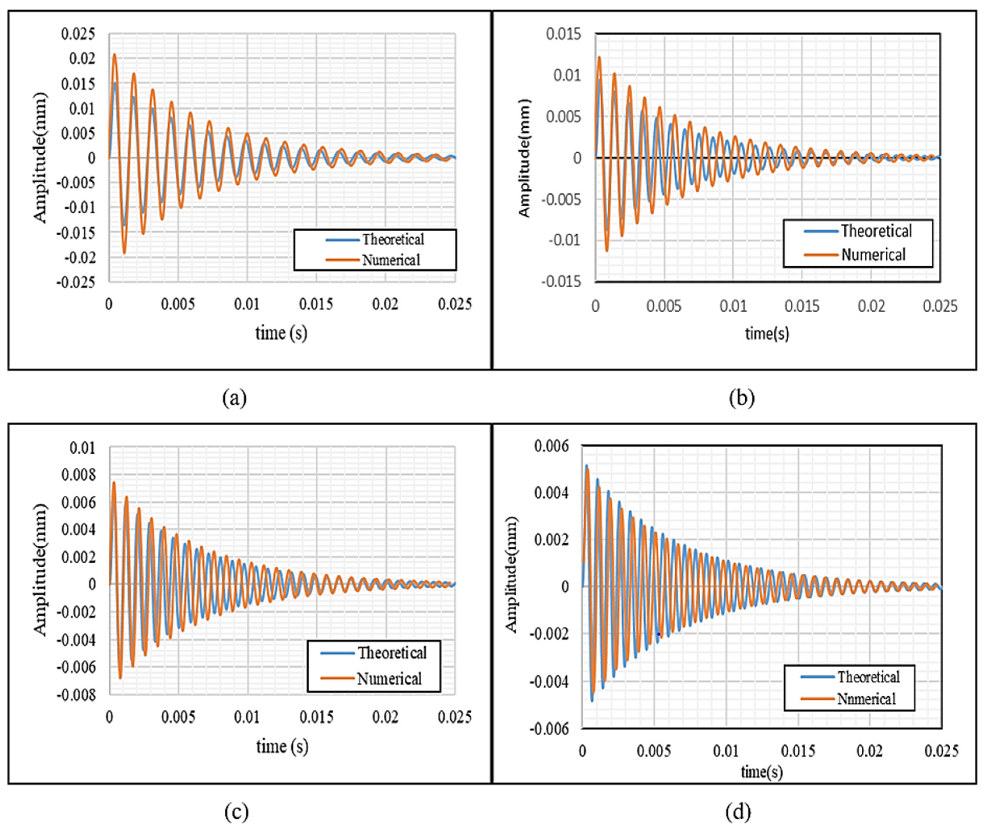
A comparison is conducted between the theoretical model in (29) and the FEM model for sandwich specimens with different heights (10, 15, 20, and 25), as shown in
Figure 8. The comparison is conducted to validate the theoretical model.
A comparison between numerical and theoretical transient responses, as shown in
Figure 8, reveals a high degree of agreement with minor discrepancies. These differences can be attributed to several factors, including the idealized assumptions in the analytical model, numerical approximations in ANSYS, and discretization effects due to finite element meshing. The theoretical solution assumes small deflections and neglects damping, whereas the numerical model inherently accounts for discretized deformation behavior. Despite these differences, the overall conformity remains within an acceptable range, validating the accuracy of the proposed analytical approach.
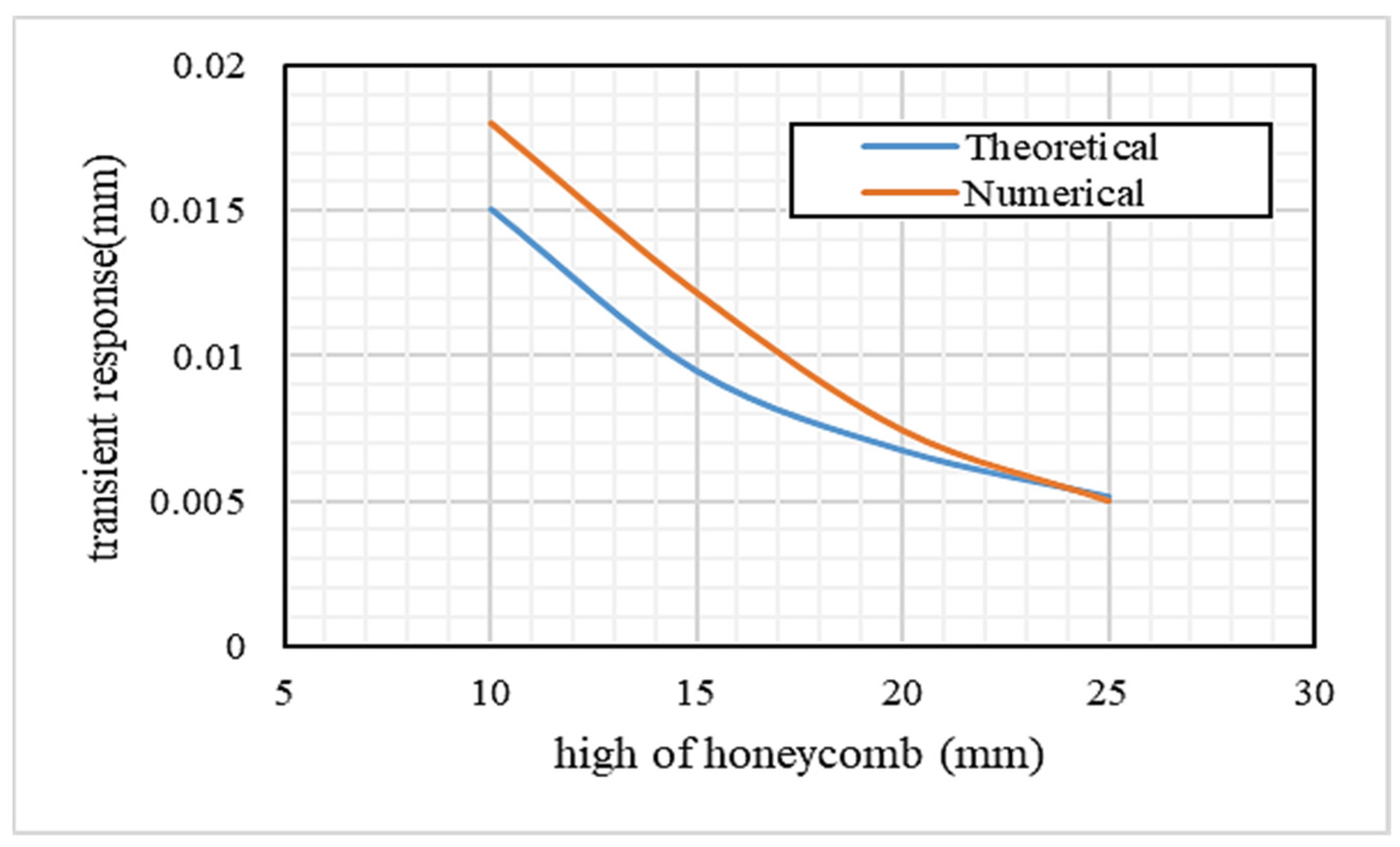
Table 2 shows a comparison between the theoretical and numerical maximum transient response and the relative error (%). The results show a good agreement between the maximum transient response variation and the core height, as plotted in
Figure 9.
The ANSYS model provides a detailed and accurate representation of a sandwich panel, including the honeycomb core, for forced vibration analysis under transient load. This model is applicable to complex and large honeycomb structures, thereby reducing the time and expense of analysis. Therefore, ANSYS 19.2 software is employed to study the effect of other parameters on the sandwich behavior under transient load.
6. Results and Discussion
The forced vibration of the honeycomb sandwich under transient load provided results that included both the transient response and the maximum transient deflection. The transient response described the sandwich’s deflection behavior over time under the transient load, while the maximum transient deflection signifies the peak of the transient response.
After making sure everything is correct, numerical and theoretical solutions are conducted to look at how the honeycomb parameters change the transient response and the maximum transient response.
Table 1 illustrates the use of cell size, core height, and cell wall thickness as honeycomb parameters.
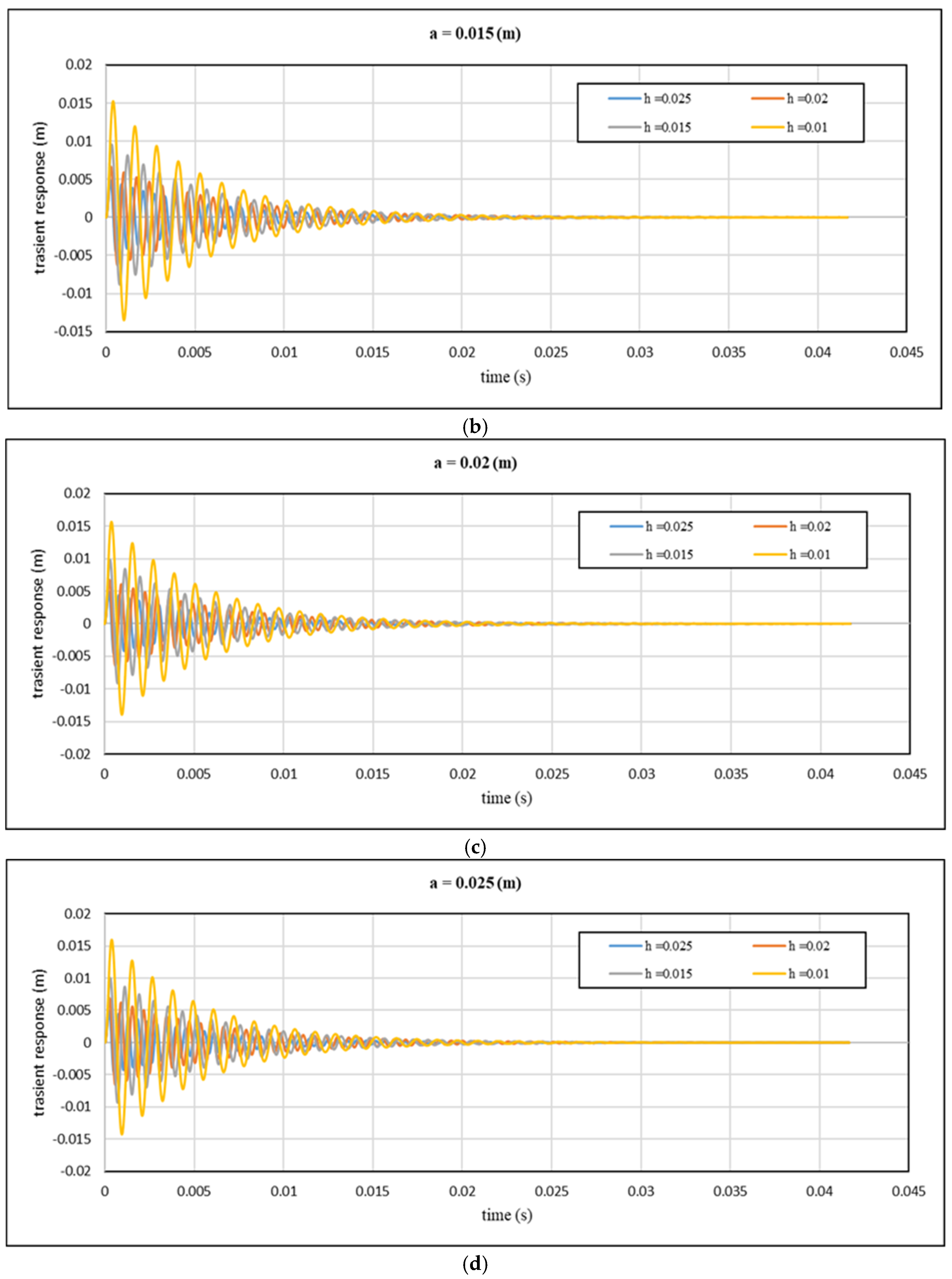
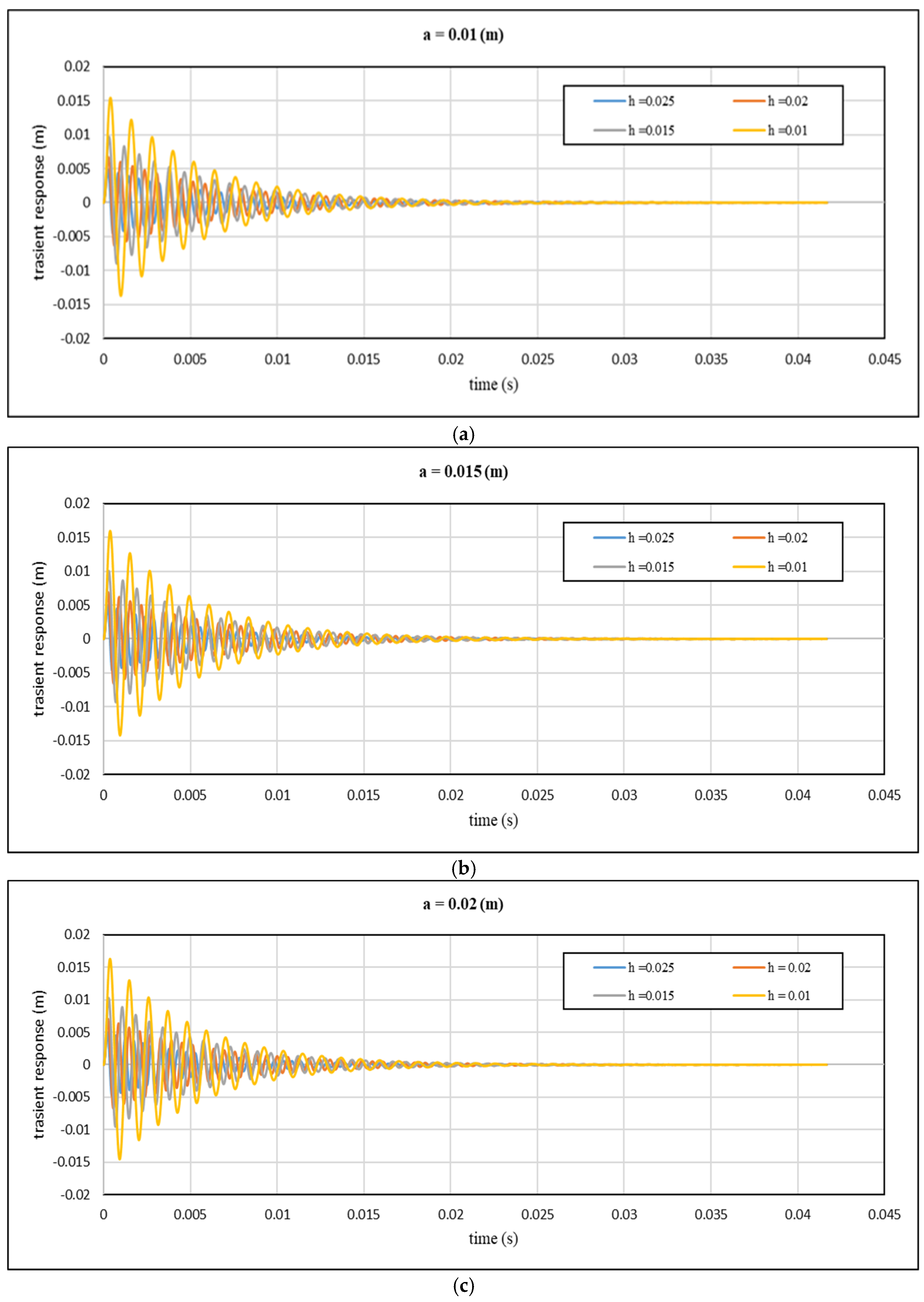
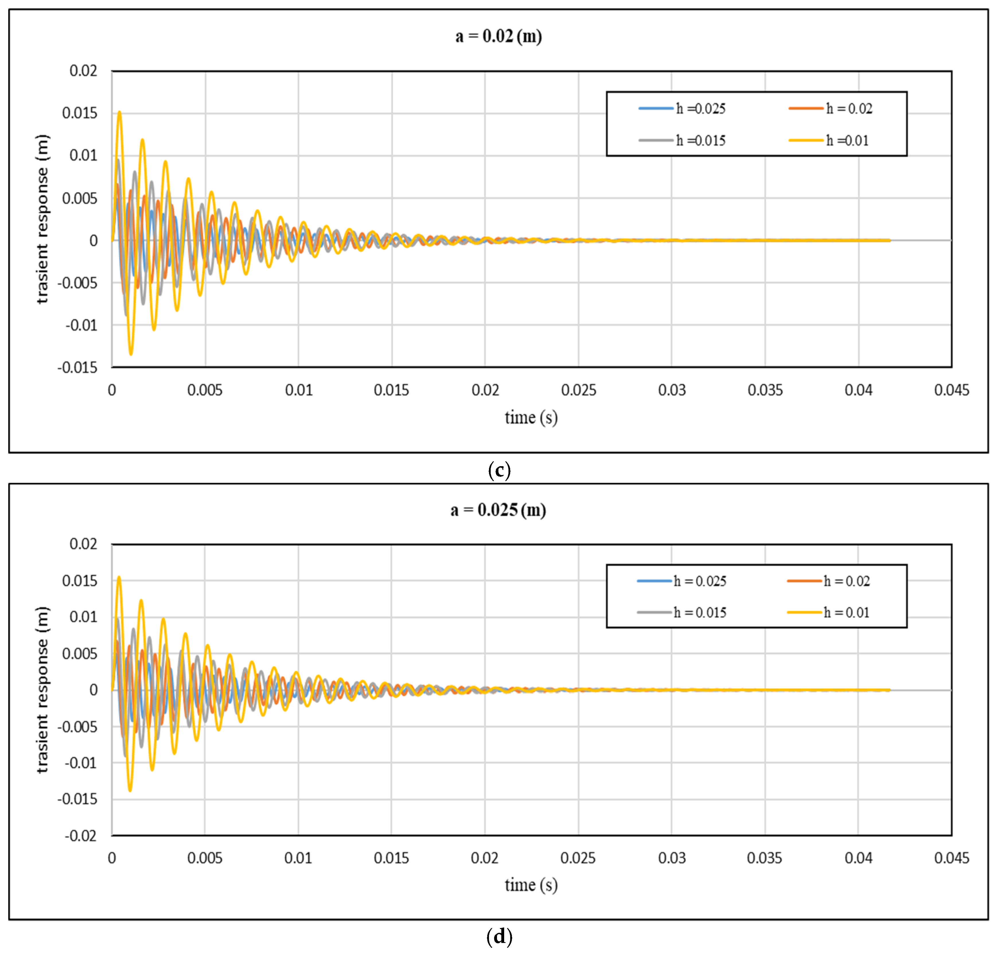
Figure 10,
Figure 11,
Figure 12 and
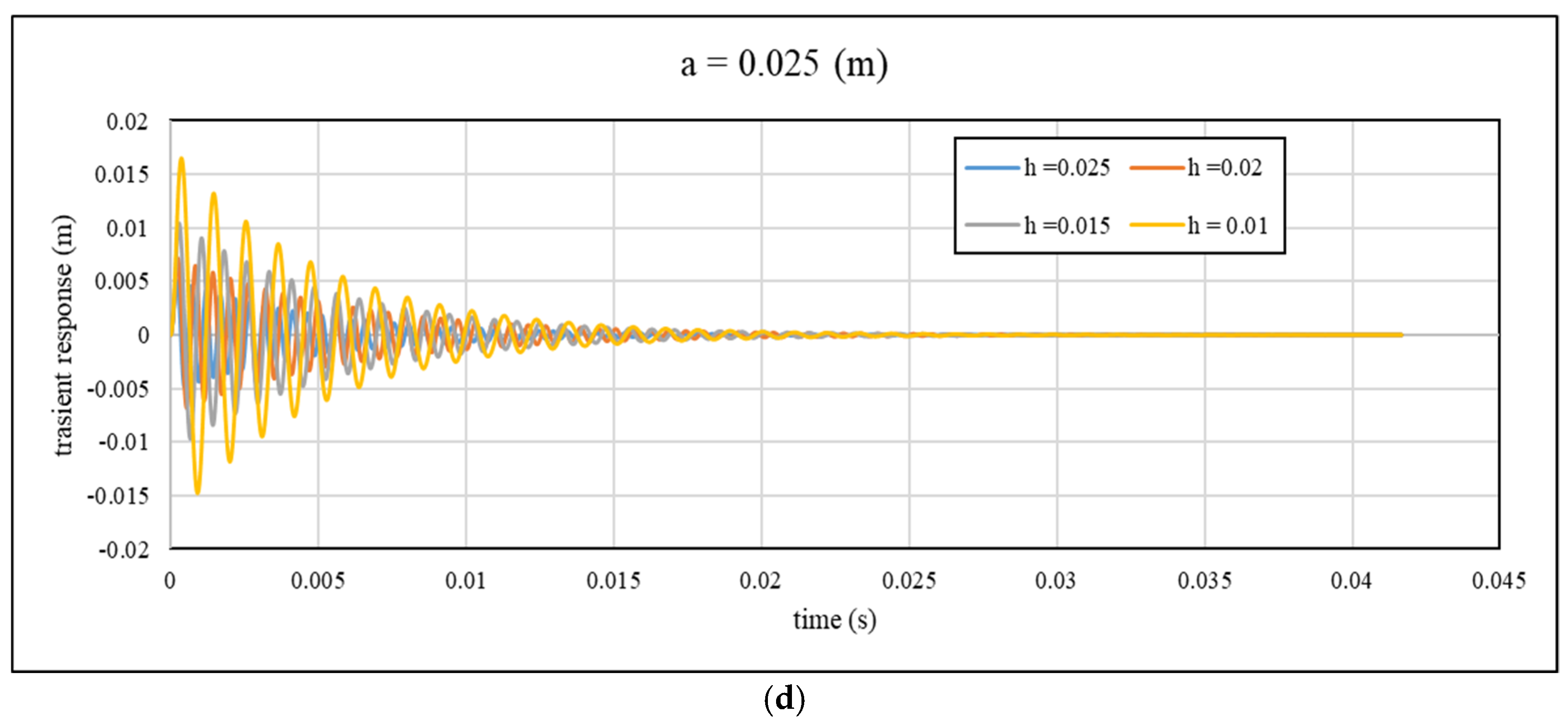
Figure 13 illustrate the theoretical transient response as a function of time and core height for various values of cell wall thickness and cell size.
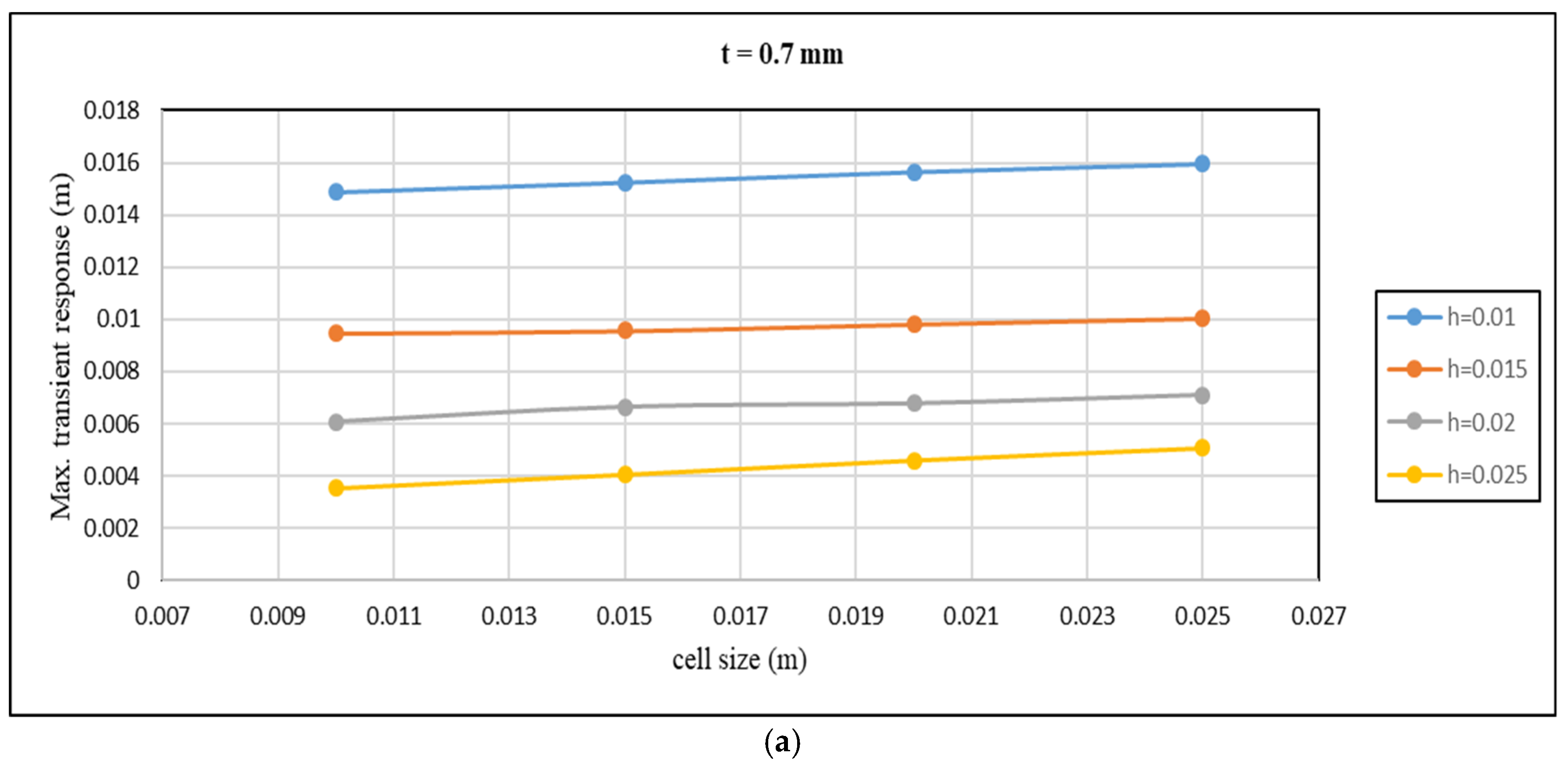
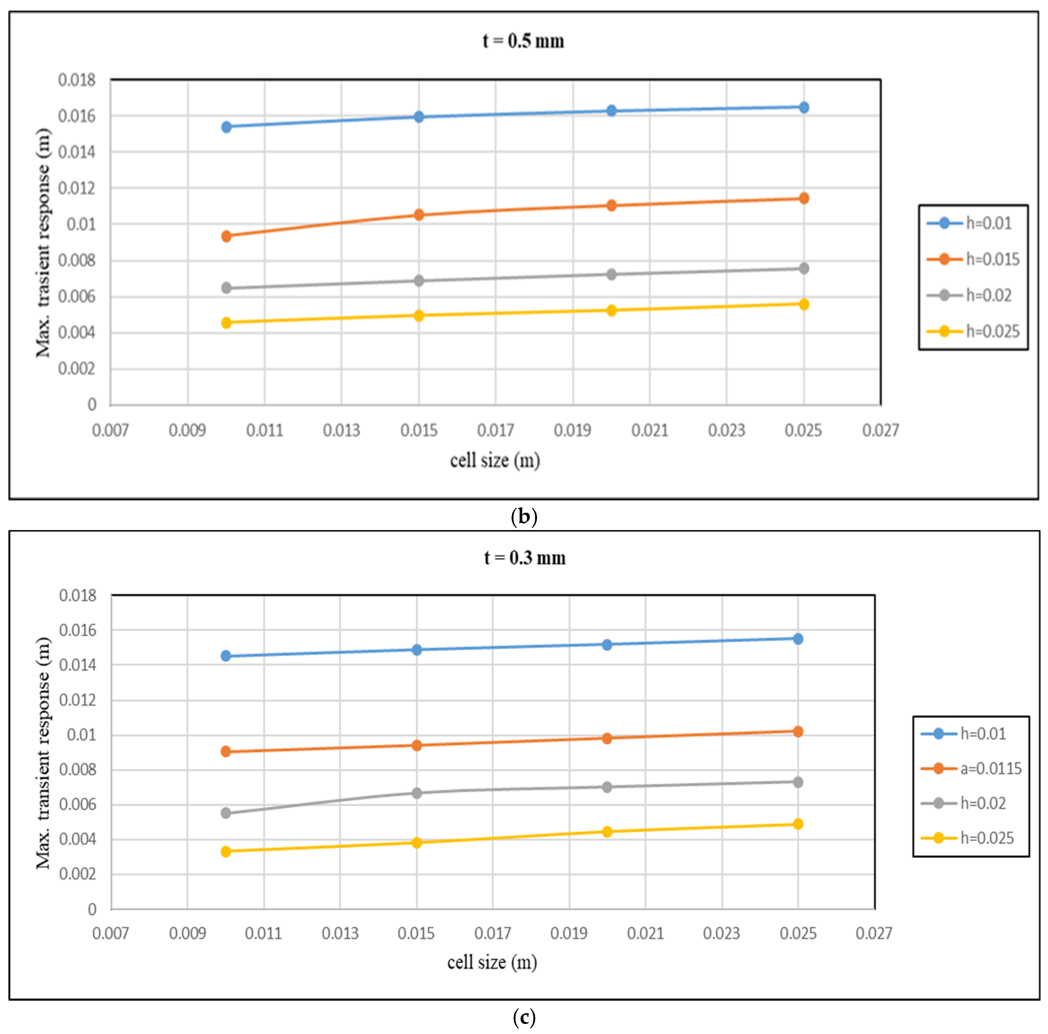
Figure 14 displays the maximum transient response variation with the cell size for different core heights and cell wall thicknesses.
Figure 14 reveals an inverse relationship between the maximum transient response and core height, with an increase in core height resulting in a decrease in the maximum transient response. The maximum transient response decreases from 0.014517551 m to 0.003332127 m when the core height increases from 10 mm to 25 mm, as shown in
Figure 14a, for specific values of cell wall thickness and cell size of 0.7 mm and 10 mm, respectively.
A similar pattern can be observed in the maximum transient response with cell wall thickness, where an increase in cell wall thickness leads to a reduction in the maximum transient response. The maximum transient response drops from 0.016283581 m to 0.015186752 m when the cell wall thickness increases from 0.3 mm to 1 mm, with the core height and cell size being 10 mm and 15 mm, respectively, as illustrated in
Figure 14b.
On the other hand, an increase in cell size positively impacts the maximum transient response. Specifically, the response increases from 0.014877616 m to 0.0162519 m when the cell size increases from 0.01 m to 0.025 m at the core height, with cell wall thicknesses of 0.01 m and 0.7 mm, as depicted in
Figure 14c.
7. Conclusions
The increase in core height from (0.01 to 0.025) m leads to a reduction in the maximum transient response by approximately 77.047%; this reduction is observed for a cell wall thickness of 0.0007 and a cell size of 0.01 m.
The variation in cell wall thickness from (0.0003 to 0.001) m led to a decrease in the maximum transient response by 6.73% at 0.01 m core height and 0.015 m cell size values.
Cell size has a positive effect on maximum transient response. It increases by 9.23% when cell size rises from 0.01 m to 0.025 m at the core height and cell wall thickness of 0.01 m and 0.7 m, respectively.
The variation in the core height has a greater influence than other parameters, where the cell wall size has a smaller influence on them.
Study’s Limitations and Recommendations for Future Validation
This study provides valuable insights into the transient response of honeycomb sandwich panels. However, the analytical model is based on small deformation plate theory, which assumes linear elasticity and neglects damping effects for simplification. These assumptions are valid within the studied parameter ranges, where the numerical and analytical results showed a 95% agreement. The model provides accurate predictions for core heights between 0.01 m and 0.025 m, cell wall thicknesses from 0.0007 m to 0.001 m, and cell sizes between 0.01 m and 0.025 m. It is most reliable for moderate transient loads, where linear elasticity and small deformations remain valid. However, for high-frequency loads or cases involving large deformations and material nonlinearities, the accuracy of the model may decrease, requiring experimental validation or advanced nonlinear simulations.
Future validation through experimental testing or advanced numerical simulations incorporating damping could enhance the model’s accuracy and applicability to a broader range of conditions. Additionally, incorporating nonlinear material behavior and complex boundary interactions would further refine the model’s predictive capability.
Finally, future research could focus on optimizing honeycomb parameters to enhance structural performance, particularly for aerospace applications where weight reduction and mechanical efficiency are critical. Potential optimization approaches, such as genetic algorithms (GAs), particle swarm optimization (PSO), and gradient-based optimization methods, can be utilized to achieve an optimal balance between strength, weight, and dynamic response.
Author Contributions
Conceptualization, S.E.S.; methodology, S.E.S.; software, S.E.S.; validation, S.E.S. and H.H.A.; formal analysis, S.E.S.; investigation, S.E.S. and H.H.A.; resources, S.E.S. and H.A.-B.; data curation, S.E.S.; writing—original draft preparation, S.E.S. and H.H.A.; writing—review and editing, H.A.-B. and M.K.K.; visualization, H.H.A. and M.A.F.; supervision, M.J.J. and S.H.B. All authors have read and agreed to the published version of the manuscript.
Funding
This research received no external funding.
Data Availability Statement
Most datasets generated and analyzed in this study are contained in this manuscript. Other datasets are available on reasonable request from the corresponding author with the attached information.
Conflicts of Interest
The authors declare no conflicts of interest.
Nomenclatures
| a | Length of honeycomb sandwich panels | mm |
| b | Width of honeycomb sandwich panels | mm |
| c | Core height | M |
| d | Distance between the mid-planes of the bottom and upper skins | mm |
| E | Young’s modulus of material from which the core was made | Pa |
| E3 | The out-of-plane Young’s modulus of the core of honeycomb | Pa |
| Ea | Energy absorption | J |
| Ef | Modulus of skin elasticity | Pa |
| Eh12 | In-plane Young’s modulus of honeycomb core in 1-direction | Pa |
| Eh21 | In-plane Young’s modulus of honeycomb core in 2-direction | Pa |
| Eh31 | Out-of-plane Young’s modulus of honeycomb core in 3-direction | Pa |
| Elp | Young’s modulus of lower plate | Pa |
| Eup | Young’s modulus of upper plate | Pa |
| F(x,y,t) | External excitation fore | N |
| F0 | Amplitude of excitation | N |
| G | Shear modulus of material from which the core was made | Pa |
| Gc | The core out-of-plane shear modulus of the core | Pa |
| Gh12 | In-plane shear modulus of honeycomb core in 1-direction | Pa |
| Gh21 | In-plane shear modulus of honeycomb core in 2-direction | Pa |
| Gh31 | Out-of-plane shear modulus of honeycomb core in 3-direction | Pa |
| Glp | Shear modulus of lower plate | Pa |
| Gup | Shear modulus of upper plate | Pa |
| h | Height of honeycomb sandwich panels | mm |
| hh | Honeycomb core height | mm |
| hlp | Height of lower plate | mm |
| hup | Height of upper plate | mm |
| I | Sandwich second moment of area | m4 |
| Keq | Equivalent stiffness | N/m |
| L | Length of honeycomb sandwich | m |
| M | The maximum bending moment at the mid-span | N·m |
| meq | Equivalent mass | kg |
| Mx | Direct bending moment in x-direction | N·m |
| Mxy | Twisting bending moment | N·m |
| My | Direct bending moment in y-direction | N·m |
| t | Cell wall thickness of honeycomb core | mm |
| Tc | Cell wall thickness | m |
| W(x,y,t) | Vibration response of sandwich panels in z-direction | mm |
| In-plane Poisson’s ratio of honeycomb core in 1-direction | - |
| In-plane Poisson’s ratio of honeycomb core in 2-direction | - |
| Out-of-plane Poisson’s ratio of honeycomb core in 3-direction | - |
| Poisson’s ratio of lower plate | - |
| Density of honeycomb core | kg/m3 |
| Density of core | kg/m3 |
| Density of material from which the core was made | kg/m3 |
| Density of upper plate | kg/m3 |
| A | The size of cell | degree |
| Θ | Cell angle of honeycomb core | degree |
| Ν | Poisson’s ratio of material from which the core was made | - |
| νf | Poisson’s ratio of face | - |
| νup | Poisson’s ratio of upper plate | - |
| ξ | Damping ratio | - |
| σfw | Critical compressive shear | Pa |
| σfw | Critical compressive stress which caused the upper skin wrinkling | Pa |
| σfx | Maximum stress of the skins | Pa |
| σfy | Yield stress of face | Pa |
| σx | Normal stress in x-direction | Pa |
| σxy | Shear stress in xy-plane | Pa |
| σy | Normal stress in y-direction | Pa |
| σyc | The core compressive strength | Pa |
| τc | Shear stress of core | Pa |
| τcy | Yield shear stress of core | Pa |
| ω1 | First bandwidth frequency | rad/s |
| ω2 | Second bandwidth frequency | rad/s |
| ωn | Natural frequency | rad/s |
| Density of material from which the core was made | kg/m3 |
References
- Gao, Y.; Huang, H. Equivalent damper model for honeycomb structures. Int. J. Mech. Mater. Des. 2022, 18, 475–490. [Google Scholar] [CrossRef]
- Al-Baidhani, H.; Kazimierczuk, M.K. Design and Implementation of Digital PID Control for Mass-Damper Rectilinear Systems. Mathematics 2024, 12, 2921. [Google Scholar] [CrossRef]
- Boado-Cuartero, B.; Pérez-Álvarez, J.; Roibás-Millán, E. Material Characterization of High-Performance Polymers for Additive Manufacturing (AM) in Aerospace Mechanical Design. Aerospace 2024, 11, 748. [Google Scholar] [CrossRef]
- Simões, S. High-Performance Advanced Composites in Multifunctional Material Design: State of the Art, Challenges, and Future Directions. Materials 2024, 17, 5997. [Google Scholar] [CrossRef] [PubMed]
- Parveez, B.; Kittur, M.I.; Badruddin, I.A.; Kamangar, S.; Hussien, M.; Umarfarooq, M.A. Scientific Advancements in Composite Materials for Aircraft Applications: A Review. Polymers 2022, 14, 5007. [Google Scholar] [CrossRef] [PubMed]
- Wolff, M.; Abada, H.H.; Saad, H.A.K. Numerical Investigation of Supersonic Flow over a Wedge by Solving 2D Euler Equations Utilizing the Steger–Warming Flux Vector Splitting (FVS) Scheme. Mathematics 2024, 12, 1282. [Google Scholar] [CrossRef]
- Sadiq, S.E.; Bakhy, S.H.; Jweeg, M.J. Optimum vibration characteristics for honeycomb sandwich panel used in aircraft structure. J. Eng. Sci. Technol. 2021, 16, 1463–1479. [Google Scholar]
- Huang, H.; Han, Q.; Wu, B.; Zhu, R.; Wang, G. Design and vibration reduction performance of honeycomb sandwich support rod for wind tunnel. J. Mech. Sci. Technol. 2024, 38, 527–539. [Google Scholar] [CrossRef]
- Ullah, I.; Elambasseril, J.; Brandt, M.; Feih, S. Performance of bio-inspired Kagome truss core structures under compression and shear loading. Compos. Struct. 2014, 118, 294–302. [Google Scholar] [CrossRef]
- Castanie, B.; Bouvet, C.; Ginot, M. Review of composite sandwich structure in aeronautic applications. Compos. Part C Open Access 2020, 1, 100004. [Google Scholar] [CrossRef]
- Şakar, G.; Bolat, F.Ç. The Free Vibration Analysis of Honeycomb Sandwich Beam using 3D and Continuum Model. World Academy of Science. Engineering and Technology. Int. J. Mech. Mechatron. Eng. 2015, 9, 1077–1081. [Google Scholar]
- Harish, R.; Sharma, R. Vibration response analysis of honeycomb sandwich panel with varying Core Height. IJETCAS 2013, 5, 582–586. [Google Scholar]
- Naresh, C.; Gopi Chand, A.; Sunil Ratna Kumar, K.; Chowdary, P.S.B. Numerical Investigation into Effect of Cell Shape on the Behavior of Honeycomb Sandwich Panel. IJIRSET 2013, 2, 8017–8022. [Google Scholar]
- Jweeg, M. A Suggested Analytical Solution for Vibration of Honeycombs Sandwich Combined Plate Structure. IJMME 2016, 16, 9–17. [Google Scholar]
- Mei, B.; Alamri, S.; Jalil, A.T.; Hadrawi, S.K.; Khan, I.; Baghaei, S. Wave propagation and vibration analysis of sandwich structure with a bio-based flexible core and composite face sheets subjected to visco-Pasternak foundation and magnetic field. Compos. Struct. 2022, 300, 116132. [Google Scholar] [CrossRef]
- Al-Khazraji, M.S.; Jweeg, M.J.; Bakhy, S.H. Free vibration analysis of a laminated honeycomb sandwich panel: A suggested analytical solution and a numerical validation. J. Eng. Des. Technol. 2022, 22, 316–343. [Google Scholar] [CrossRef]
- Quan, T.Q.; Anh, V.M.; Duc, N.D. Natural frequency analysis of sandwich plate with auxetic honeycomb core and CNTRC face sheets using analytical approach and artificial neural network. Aerosp. Sci. Technol. 2023, 144, 108806. [Google Scholar] [CrossRef]
- Zhao, X.; Wang, H.; Zhu, W.; Li, Y. Forced transient vibration analysis of a multi-cracked bridge model under moving loads by means of Green’s functions. Arch. Appl. Mech. 2023, 93, 3895–3920. [Google Scholar] [CrossRef]
- Chakraverty, S. Vibration of Plates, 1st ed.; CRC Press: Boca Raton, FL, USA, 2008; p. 411. [Google Scholar]
- Leissa, A.W.; Qatu, M.S. Vibration of Continuous Systems, 1st ed.; McGraw Hill Education: Ney Work, NY, USA, 2011; p. 479. [Google Scholar]
- Nast, E. On honeycomb-type core moduli. In Proceedings of the 38th Structures, Structural Dynamics, and Materials Conference, Kissimmee, FL, USA, 7–10 April 1997; pp. 1035–1045. [Google Scholar] [CrossRef]
- Liu, Q.; Zhao, Y. Effect of Soft Honeycomb Core on Flexural Vibration of Sandwich Panel using Low Order and High Order Shear Deformation Models. J. Sandw. Struct. Mater. 2006, 9, 95–108. [Google Scholar] [CrossRef]
- Roa, S. Mechanical Vibrations, 5th ed.; Pearson Education: Noida, India, 2010; p. 1104. [Google Scholar]
| Disclaimer/Publisher’s Note: The statements, opinions and data contained in all publications are solely those of the individual author(s) and contributor(s) and not of MDPI and/or the editor(s). MDPI and/or the editor(s) disclaim responsibility for any injury to people or property resulting from any ideas, methods, instructions or products referred to in the content. |
© 2025 by the authors. Licensee MDPI, Basel, Switzerland. This article is an open access article distributed under the terms and conditions of the Creative Commons Attribution (CC BY) license (https://creativecommons.org/licenses/by/4.0/).


 ,
, 


