Abstract
Mobile robots are widely used, with research focusing on autonomy and functionality. However, long-term deployment requires their health and safety to be ensured. Terrain-induced vibrations accelerate wear. Hence, self-awareness and optimal path selection, avoiding such terrain anomalies, is essential. This study proposes an RL-based vibration-aware path planning framework, incorporating terrain roughness level classification, a vibration cost map, and an optimized vibration-aware path planning strategy. Terrain roughness is classified into four levels using IMU sensor data, achieving average prediction accuracy of 97% with a 1D CNN model. A vibration cost map is created by assigning vibration costs to each predicted class on a 2D occupancy grid, incorporating obstacles, vibration-prone areas, and the robot’s pose for navigation. An RL model is applied that adapts to changing terrain for path planning. The RL agent uses an MDP-based policy and a deep RL training model with PPO, taking the vibration cost map as input. Finally, the RL-based vibration-aware path planning framework is validated through virtual and real-world experiments using an in-house mobile robot. The proposed approach is compared with the A* path planning algorithm using a performance index that assesses movement and the terrain roughness level. The results show that it effectively avoids rough areas while maintaining the shortest distance.
Keywords:
terrain classification; condition monitoring; path planning; 1D CNN; reinforcement learning; mobile robots; operational safety MSC:
68T40; 68T01; 68T07; 93C85
1. Introduction
Autonomous mobile robots are everywhere today, providing various services, such as cleaning, logistics, inspection, and security. They reduce the human effort needed to perform repetitive, unhygienic, and unsafe tasks and help to solve labor-related availability, cost, and quality problems. Studies show that there is a vast market for service robots, estimated to be valued at USD 243.9 billion by 2030, compared to USD 36.5 billion in 2021 [1]. Many research works have been published that enhance the fundamental techniques of robotics, mainly seeking to develop their autonomous behavior and functional performance. Specific aspects include better area coverage [2,3], optimized path planning [4,5], perception [6,7], performance measurement [8,9], energy efficiency [10,11], human–robot interaction [12], and fleet management [13]. Many mobile robots are deployed in human-shared workplaces; hence, the robot’s health and operational safety are vital. In this context, the current studies are more focused on avoiding collisions with static and dynamic large obstacles in their heading direction [14,15]. However, research on the various factors causing accelerated system degradation, sources of failure or abnormal operation, condition monitoring (CM) methods, and possible ways to minimize such exposure is rare regarding mobile robots. Towards this goal, we have recently developed three CM frameworks using different sensors, mainly an inertial measurement unit (IMU), a monocular camera, and a combination of an IMU and current sensors [16,17,18] for indoor mobile robots. Uneven, unstructured, and rough terrain are significant but rarely considered factors causing accelerated deterioration in mobile robots. CM studies enable the detection of any potential failure. However, avoiding such terrain-related anomalies is a more productive solution, especially when the robot is deployed in a particular workspace for repetitive tasks, such as inspection, logistics, patrolling, etc. Hence, this study proposes a new path planning strategy to minimize the robot’s traversal over undesirable terrain, thereby enhancing its reliability and operational safety.
1.1. Problem Statement
Manufacturers and contract companies mostly carry out manual supervision and periodic maintenance to monitor and resolve their robots’ system degradation and operational safety-related concerns. However, this consumes time, is skill-set-dependent, and leads to the underutilization of components. The degradation rate or maintenance costs greatly depend on the nature of the deployment environment, mainly in terms of the roughness levels of floors, various floor objects, and imperfections. Although the floor roughness and types of surface imperfections vary from building to building, the current practice involves an hourly or monthly-based fixed rental charge [19]. In addition, the number of floor imperfections may become worse over time or due to dynamic environmental or climatic changes. To date, various path planning approaches have been studied, considering the area coverage, distance, time, and energy [4,20,21,22,23,24] associated with mobile robots. However, no path planning strategies are available that focus on terrain-induced vibration as a cost factor to minimize system degradation and avoid operational hazards in mobile robots. Hence, a real-time terrain-induced vibration class-aware CM framework is needed, as well as the continuous learning and updating of terrain anomalies due to dynamic changes in the terrain state and the selection of a path by eliminating such terrain features. Towards this goal, this study proposes a novel vibration-aware path planning optimization strategy that avoids the traversal of extremely rough terrain areas to enhance the system’s reliability and operational safety.
Floors, especially those in large workplaces, are usually composed of different materials with varied textures or roughnesses. Various floor components, such as tactile pavements, power pockets, and grip platforms for escalator areas, are also observed. There could also be other floor imperfections, such as cable routing, small steps or slopes due to unevenly paved tiles, and gutters or broken floors due to poor workmanship or maintenance, poor material quality, or aging. All of these factors generate terrain-induced vibration in an indoor mobile robot, which results in faster system degradation and wear, misalignment, wobbling or damage to the drive wheels, shorter life cycles for the payload and other critical parts, imbalanced structures, performance degradation, sensor accuracy errors, unplanned downtime, catastrophic failures, higher maintenance costs, and safety issues. These floor-level objects, imperfections, and floor textures are not captured as obstacles in the 2D LiDAR-generated grid map for robot navigation. In our previous CM case studies [16,17,18] focused on predicting the sources of anomalous vibration in a mobile robot, the robot failed due to severe wheel wobbling in two weeks when deployed on concrete with a small pebble-paved corridor. After one month of continuous running, a similar but minor failure was noticed when tested on a regular concrete floor. Hence, it is essential to create an automated system that is aware of the roughness or imperfections of floors based on the level of vibration induced and to select a path that avoids such vibration-prone areas in its next cycle of operation.
1.2. Research Contributions
The main research contributions of this work are summarized below.
- The change in the robot’s linear and angular motion due to extremely rough terrain is captured using an onboard IMU sensor and modeled as vibration-indicated data.
- The robot’s vibrations due to rough terrain features are classified into four levels, from very smooth to very rough and from safe to unsafe, and a real-time vibration class prediction model is developed, adapting a 1D CNN-based model.
- An algorithm is formulated to fuse the vibration cost, assigned to each vibration class predicted for every footprint of the robot, and a 2D occupancy grid map of the robot’s workspace, and we develop a vibration cost map. This map contains profiles of obstacles, the roughness score of the workspace at a unit area, and the robot’s pose for navigation.
- A novel RL-based vibration-aware path planning strategy for indoor mobile robots is proposed, using the vibration cost map as input and aiming to minimize system deterioration by avoiding traversal through extremely rough terrain. This is realized by
- modeling an RL policy function for vibration state rewards as a Markov Decision Process (MDP).
- modeling a deep RL training model to fine-tune the policy via Proximal Policy Optimization (PPO).
- We validate the proposed framework through virtual and real-time case studies with an in-house-developed autonomous mobile robot. In addition, we compare it with the robot’s existing A*-based path planning strategy by proposing a performance index in terms of the total movement (distance) and roughness scores.
The outline of this paper is as follows. Section 2 explains the related works published. Section 3 provides an overview of the proposed system, consisting of a terrain-induced vibration classification model, vibration cost map generation, and an RL framework. Section 4 elaborates on the training models, evaluations, and results. Section 5 explains the real-time field case studies and results. Finally, Section 6 summarizes the present work.
2. Related Works
Several vibration data-based studies have been conducted for applications such as monitoring abnormal working conditions in various systems and traversability assessment for mobile robots. Vibrations induced by different indoor floors—ceramic tiles, linoleum, carpet, and terrazzo—were classified using an IMU sensor and linear Bayes normal classifier model to ensure the smooth operation of wheeled mobile robots in [25]. Similarly, a terrain classification study on terrain obstacles in the human environment was conducted in [26] to distinguish traversable regions based on 2D LiDAR data and the support vector data description (SVDD) technique. However, the majority of the terrain-based classification studies [27,28,29] have been conducted for the maneuverability assessment of outdoor mobile robots and autonomous ground vehicles, distinguishing between concrete, sand, gravel, grass, and mud. Meanwhile, studies on the classification of the roughness and imperfection levels of indoor floors for the optimization of path planning are rare in terms of indoor mobile robots. Developing a suitable AI classification model based on the nature of raw data, with high training accuracy and fast and easy execution for real-time applications, is critical. The 1D CNN model is widely used in vibration data-based studies, especially for CM applications, due to its low computational complexity and ease of configuration [30]. For instance, it has been examined regarding the abnormal operation of bearings [31], motors [32], structural systems [33], and industrial robots [34].
Feasible and optimal path planning is essential for the efficient performance of mobile robots. Graph search algorithms, such as Dijkstra’s algorithm [35] and A* [36], are popular in terms of obtaining the path with the lowest cost. Furthermore, extensions of the A* algorithm, such as D* [37] and D* Lite [38], have been developed, which incorporate any changes in the path planning graph using heuristics for fast replanning. Voronoi diagram-based path planning for mobile robots [39,40] is helpful for shorter paths and unknown static obstacles, enabling real-time path planning. However, the work in [41] shows the limitations of the above typical algorithms, such as slow speeds (Dijkstra), proximity to obstacles (A*), and not considering vehicle constraints (Voronoi). Sampling-based algorithms such as Probabilistic Roadmaps (PRM) [42] and Rapidly Exploring Random Trees (RRT) [43] work well in solving path planning problems in high-dimensional configuration spaces, by connecting a set of points sampled from an obstacle-free space and delivering a graph of feasible trajectories. As PRM is based on random sampling, there are possibilities for unconnected graphs at narrow passages, unless the number of nodes increases, bringing a higher computational cost. The standard RRT algorithm also shows limitations, like poor performance in narrow passages. The kinematically feasible path is equally as important as the minimum path cost in mobile robots. For instance, the Lattice planner [44,45] is a graph-based path planning algorithm that sets a search space (state lattice) for constrained motion planning and enables the uniform discretization of vertices, extending to the equivalent positions and headings to form feasible motion primitives. Compared to classical methods, evolutionary methods such as the genetic algorithm (GA) [46], ant colony optimization (ACO) [47], particle swarm optimization (PSO) [48], and simulated annealing (SA) [49] are found to be faster in solving path planning problems. However, the dynamically changing terrain-related features are not considered in these approaches as a cost factor in view of the robot’s health.
In recent years, the exploration of unstructured and dynamically changing unknown environments using RL techniques has been widely conducted regarding the application of motion planning in mobile robots [50,51,52,53]. This intelligent learning-based path planning approach helps in reducing the programming complexity and eliminates the slow convergence and dependency on prior environmental knowledge compared to traditional graph, sampling, and evolutionary path planning methods. A deep Q-network (DQN)-based global path planning method is presented in [54] for mobile robots in dense environments, using RGB images as input to the DQN. The authors compared the model’s efficiency with that of the A* and Dijkstra algorithms and found that it was much faster due to inferring the optimal path and avoiding obstacles. As per [55], the DQN approach is limited to discrete action spaces; hence, they proposed a soft actor–critic (SAC) algorithm for mobile robots, with continuous numerical values and a potential energy function for improved rewards. This avoids static and dynamic obstacles without prior knowledge in complex environments. The Reconfigurable Structure of Deep Deterministic Policy Gradient (RS-DDPG) was applied for mobile robots in unknown dynamic environments in [56]. Here, the authors used an event-triggered reconfigurable actor–critic network to avoid overestimating the action value, improved the time convergence with a minor valuation deviation, added an adaptive reward mechanism due to the lack of sample information, and used a sample pretreatment method for better learning efficiency. A visual-guided tracking task issue in a snake-like robot with many joints was solved using a model-free RL algorithm in [57], mapping the vision space to a joint space. For this perception to action control task, Proximal Policy Optimization (PPO) was adopted to train the network, as PPO is easy to implement and performs better in continuous action spaces [58]. Besides perception and navigation, the RL approach was applied for a search and rescue task in [59], where an A3C network with frontier exploration was used.
Studies on obtaining a smooth path in an unstructured environment constitute another emerging area in path planning approaches. Considering the unstructured characteristics of the environment, an improved A*-based local motion planning algorithm was proposed in [60] for autonomous vehicles. Similarly, an improved A* algorithm suitable for long-distance off-road path planning was developed using a terrain data map in [61]. A human-like motion planning tool suitable for mobile robots deployed in indoor complex environments was introduced in [62], where it ensured foreseeability, flexibility, velocity-adjustable trajectory planning, addressing the constraints of both the robot and environment. An energy-aware path planner for mobile robots deployed in uneven terrain environments was proposed in [63], where the sequential context of traversed terrain was captured using a 1D CNN and correlated with the assessed terrain point clouds to determine the energy used.
The above works show that many path planning and optimization algorithms and their improved or hybrid versions have been developed, including AI-supported terrain classification works focusing on mobile robots. These mainly focus on the minimum path length, time, energy, computational costs, avoidance of obstacles, and plausible trajectories. However, there are no vibration-based path planning strategies for indoor mobile robots considering degradation due to the dynamically changing roughness and imperfections of various floors in large workplaces. Thus, the goal of this study was to develop a deep reinforcement learning (DRL)-based feasible path planning strategy, avoiding dynamically changing and unknown terrain-induced abnormal vibrations, for an autonomous indoor mobile robot. This enables the minimization of accelerated system degradation, reduced maintenance costs, and the avoidance of operational hazards due to unexpected wheel wear or damage, wobbling, and loose sensor assemblies.
3. Overview of the Rl-Based Vibration-Aware Path Planning Framework
The proposed RL-based vibration-aware path planning strategy to minimize system degradation in indoor mobile robots is illustrated in Figure 1. It is obtained mainly by developing three frameworks: a terrain-induced vibration/roughness class prediction model, a vibration cost mapping module, and an RL-based path planning framework for robot navigation, avoiding extreme rough terrain features. The following sections elaborate on the approaches and methodologies developed for these models/frameworks.
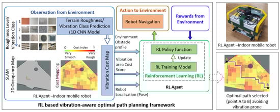
Figure 1.
Overview of the RL-based vibration-aware path planning framework.
3.1. Terrain-Induced Vibration Classification Framework
3.1.1. Autonomous Indoor Mobile Robot—Test Platform
An in-house-developed autonomous indoor mobile robot, as shown in Figure 2, is used for vibration-affected data acquisition experiments and real-time case studies to validate the proposed system. The robot is originally designed for the disinfection of indoor floors such as tile, concrete, carpet, vinyl, and sealed wood floors using steam. The robot’s architecture is briefly described as follows. The overall size of the robot is 40 × 40 × 38 cm, with a total weight of 20 Kg. It includes a 40 Ah Li-ion battery, 2000 W inverter, 1300 W boiler, mopping head assembly, and ruggedized metallic structure. A differential drive kinematics mechanism supported by two caster wheels governs the robot’s maneuverability. For environmental localization and mapping, a 360° covered 2D LiDAR scanner (RPLIDAR A2) is mounted on top of the robot. A Vectornav VN-100 IMU sensor is fixed firmly with the metal base plate of the robot to assess the position and orientation. An NVIDIA Jetson AGX Xavier computer manages all operations, such as autonomous navigation and sensor control, including the real-time CM and path planning framework. Meanwhile, a D-Link 4G/LTE mobile router is integrated for the remote monitoring of abnormal roughness classes. The architecture of this indoor mobile robot has been described in our earlier work [64].
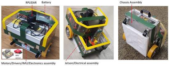
Figure 2.
Test platform: autonomous indoor mobile robot.
3.1.2. Vibration-Based Terrain Roughness Classification and Data Acquisition
Numerous terrain floors with different textures, roughnesses, and imperfections are studied for effective terrain-induced vibration or roughness level classification and also for the acquisition of vibration data for each class. Accordingly, a total of 36 indoor floor environments are selected for training data acquisition, which include typical floors built using materials of different roughnesses (concrete, marble, different textured tiles, vinyl, carpet, small pebble paving, etc.), as well as typical floor objects and imperfections (power cable routing and junction boxes, various tactile pavements, gaps or misalignment due to poor workmanship, damaged or broken floors, etc.), and we segregate them based on the roughness level and vibration amplitude level into four classes—very smooth, smooth, rough, and very rough—as shown in Figure 3. Depending on the roughness, floor features, or imperfections, the robot vibrates at different amplitudes. A higher system degradation rate is expected when exposed to the very rough class. As terrain-induced vibrations affect the linear and angular motion of a mobile robot, we use the onboard Vectornav VN-100 IMU sensor to record the linear acceleration (X, Y, and Z-axis) and angular velocity (roll, pitch, and yaw) based on the accelerometer and gyroscope of the IMU sensor, respectively. The data acquisition algorithm also calculates the angular acceleration in three axes from the current and previous angular velocity measured for each instance to strengthen the dataset for better training accuracy. Hence, nine sensor data are collected as vibration data for each class by exposing the robot to the aforementioned varied terrain environments. We set the same operating speed for the robot, 0.08 m/s, during the data acquisition stage. The IMU data subscription rate is set at 100 Hz and we group each sensor datum (process window size) into 128 elements. Hence, each dataset is modeled as [128 × 9]. Here, compared to the previous IMU-based work [16], a faster subscription rate is set, without affecting the prediction accuracy, as only terrain-induced vibration is studied in this work. Hence, a faster real-time prediction rate is achieved, i.e., a prediction every 1.28 s based on the process window size of 128. A time–amplitude graph is plotted for a single time step (128 temporal data), showing the distinct vibration signal variations across the four roughness level classes, as shown in Figure 4. One of the data features, angular acceleration, is only shown for visualization purposes. Finally, the data are compiled into a 3-dimensional input array [n × 128 × 9] (number of samples, time step, and the nine sensor data features) and we label the respective classes as input data for the 1D CNN-based model’s training.
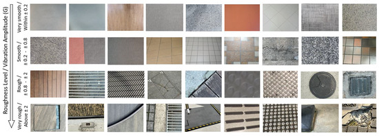
Figure 3.
Various floor types and imperfections tested for training data acquisition.
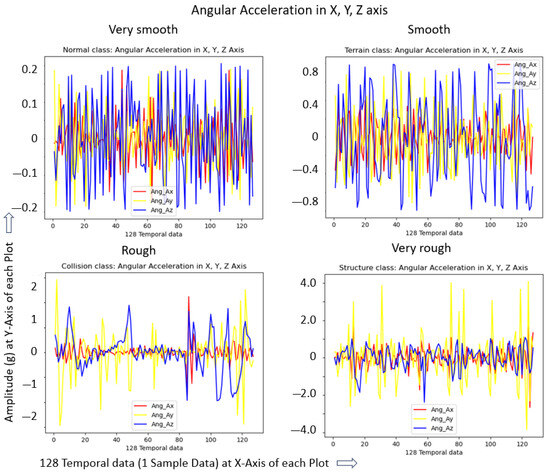
Figure 4.
Roughness/vibration levels: visual representation of four classes.
3.1.3. 1D CNN Model Structure for Roughness Level Classification
A low-computational-cost, fast, and high-accuracy model is vital for a classifier, especially for real-time applications. Hence, we adapted a 1D CNN-based model and structured it with the minimum number (four) of convolutional layers. The proposed 1D CNN-based model structure, including the data shape to fit with the given IMU sensor raw data, is shown in Figure 5 and briefly described as follows. The 3D array sensor data [n × 128 × 9] was flattened for each sample to a data shape of [1 × 1152] as the input layer. A total of four convolutional layers were structured, where the first two layers used 64 filters and the rest used 32, with a kernel size of 3 for each convolutional layer. A max pooling layer (stride size 2) with a dropout layer (rate 0.2) is applied after each convolutional layer. A Rectified Linear Activation Unit (ReLU) is used as an activation function. Finally, the pooled feature map is flattened to a 1D array and passed to a fully connected layer. In the output layer, a softmax layer is used as the final activation function. For the training of the model, a total of 2000 samples were collected for each class, which were split into 80% for training and the rest for validation. Further, a new set of 500 samples of each class was recorded for the evaluation of the model. More details of this 1D CNN structure and architectural approach, including the data shape after each convolution layer, are provided in our work on IMU sensor-based vibration data classification [16].
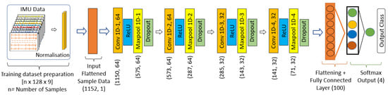
Figure 5.
The 1D CNN structure and the data shape.
3.2. Vibration Cost Mapping and Obstacle and Vibration Cost Scores
This section provides an overview of the steps applied in generating the vibration cost map for input to the proposed RL-based framework, as illustrated in the block diagram in Figure 6.
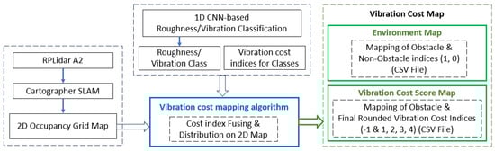
Figure 6.
Vibration cost mapping workflow.
First, a grid-based 2D occupancy map is generated for the robot’s deployment area using the onboard 2D LiDAR scanner and the Cartographer SLAM (Simultaneous Localization and Mapping) algorithm [65]. This environmental map shows the obstacle profile, i.e., the obstacles and the robot-traversable area. Next, based on the 1D CNN-based vibration class prediction algorithm, the robot scans the whole workspace to assess the vibration/roughness level of the given area. As the robot vibrates as a whole system, the robot’s footprint 0.4 × 0.4 m is taken as the unit area of vibration. The robot predicts a roughness class approximately at every 0.1 m of travel, as per the parameters set, such as the robot speed (0.08 m/s), IMU subscription rate (100 Hz), and data process window (128). Hence, there are four roughness class predictions at every footprint, which will be distributed uniformly, so that each footprint area represents a particular vibration class. The robot operating system (ROS) 2D environment map has a resolution of 0.05 × 0.05 pixels; hence, the footprint area is divided into 8 × 8 cells, i.e., each cell in the footprint is equivalent to the ROS pixel size. Based on the roughness classes predicted, cost index threshold values of 0.25, 0.50, 0.75, and 1.0 are assigned to the classes very smooth, smooth, rough, and very rough, respectively. Further, a vibration cost mapping algorithm is developed, which assigns a threshold cost index value for every roughness class predicted and fuses them at the particular unit area of the 2D SLAM map in parallel. Based on the robot’s direction, a new vibration class will be predicted, and the cost index is fused at every two columns (8 × 2) or rows (2 × 8) for the X and Y directions, respectively. However, these direction changes impact the final vibration cost map less as they are uniformly distributed at every footprint. As every new cost index is fused per th of the footprint, the cost index values will be normalized at a scale of 0 to 1 for uniform distribution. This is achieved by using a sliding window (size 8 × 8) Gaussian matrix for each predicted cost index while the robot moves. The footprint details, with the cell representation, the prediction of the classes at every stride, and the Gaussian matrix during the robot’s travel in the X direction, are represented in Figure 7. A color code scale is applied based on the normalized cost index value and we generate a vibration-aware cost map for visual representation. The cost mapping algorithm generates two CSV files as output. The first is an environment map, showing the obstacle area with an index of 1 and the non-obstacle or traversable area with 0 for the given 2D occupancy grid map. This environment map also represents the robot’s pose for navigation and localization. Secondly, a final vibration cost score is produced at every footprint based on the rounded cost value for every footprint, which is a cost score of 1, 2, 3, or 4 for the very smooth, smooth, rough, and very rough vibration classes, respectively, and all obstacles are represented as -1. Hence, this final vibration cost map contains all of the information, i.e., the obstacle profile, the vibration cost score at every footprint, and the robot’s pose.
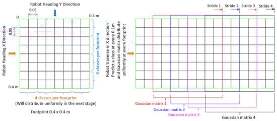
Figure 7.
Roughness class prediction and vibration cost index mapping layout.
3.3. Reinforcement Learning-Based Path Planning Framework
This section explains the formulation and modeling of the decision-making problem, adopting RL principles for robot navigation and eliminating extremely rough areas. Here, the test platform robot is used as an RL agent or learner that interacts with the environment, i.e., the floor with varied roughness features, where the agent learns and selects the navigation actions. The agent receives a reward for each action via feedback from the environment based on the roughness level score mapped in the environment. Thus, the RL agent prepares a decision-making strategy called an RL policy to map the roughness level and become aware of different vibration areas that must be avoided. The RL policy has been tuned by training and validating it based on a neural network model. We modeled the RL system as a Markov Decision Process (MDP) and used Proximal Policy Optimization (PPO) to determine the best action to be deployed based on the neural network output, as explained below.
3.3.1. Markov Decision Process
We treated the vibration level exploration task as a discrete-time finite process and modeled a mathematical framework for decision-making as per the Markov Decision Process (MDP). Accordingly, the model is defined as a tuple, accounting for the robot’s set of states (state space ), the position of the agent in the environment, the set of actions (action space ), the possible behavior of the agent, and the reward R received, while state-to-state transition is based on the action taken and represented as . The fourth element is the probability of a transition from one state to another due to the action. This probability function is stated as , i.e., the conditional probability is raised by multiplying the prior state’s probability with the updated state due to the action. The mobile robot (agent) performs observations at different states, and, at time step t, the state is , and the action performed at this discrete time is . Consequently, the reward received from the environment is . This is repeated when the agent continues to the next state at time step .
In this study, the environment is the indoor floor area, where the obstacles and different classes of roughness are expected. Hence, the action taken by the robot is to navigate from the given starting point to the destination point as per the intended application, eliminating the obstacles and minimizing the path through the rough areas, especially the extreme rough classes identified. Accordingly, the robot state at any distinct time t and the action triggered are as represented in Equations (1) and (2), respectively.
where is the robot’s location, O indicates the presence of obstacles, and V is the vibration level in the environment. Here, O is the binary representation in the 2D map, with 0 for an obstacle-free area and 1 for an obstacle area. The vibration level represents the four classes of vibration, from very smooth to very rough, i.e., = very smooth, = smooth, = rough, and = very rough. The possible motion primitives of the robot are defined as actions , which consist of moving left, right, forward, and backward.
The indoor mobile robot (RL agent) gains a reward from the workspace environment as per each action performed at a particular vibration level and obstacle state. The reward function is defined by mapping the state–action pairs to a real number, expressed as . Here, the reward depends on three factors: the first is the possibility of collision with obstacles; the second factor is the level of vibration that the robot experiences; and the third one is a variable indicating the new distance to the target after every movement. This reward function is represented in Equation (3). The parameters are to be avoided or minimized for smooth navigation, avoiding obstacles and extremely rough vibration-prone locations and with the minimum time (short path). Hence, when the robot exhibits such parameters, the feedback becomes a punishment factor, i.e., a negative reward.
The factor is assigned to the robot when it takes actions to move to the set of locations with a high likelihood of collision with obstacles, and this reward factor is expressed as in Equation (4).
The following parameter depends on the level of vibration. The robot’s punishment factor is expressed in Equation (5) based on the four roughness levels identified. Here, negative values are also given for the very smooth and smooth classes to avoid pursuing all positive rewards and taking a longer path to reach the target point.
The third reward factor is the new distance to the target point after every action or movement compared to the shortest path from the origin to the target point. This third factor indicates how close the target point is, and each movement is taken as the footprint size (0.4 m). This delta distance is calculated by . A is the shortest distance from the start point to the target, B is the distance to the target after every movement, and the number 4 is a scalar value. Hence, this factor will control the total path distance to reach the goal. Based on how far or near it is, a positive or negative reward will be assigned, as indicated in Equation (6).
The RL agent learns a behavior or strategy that gains the maximum rewards with the possible actions at a given state called policy . Hence, an RL policy is a probability distribution of the action attempted in a given state, expressed as . Further, in a deterministic case, the policy function maps situations to actions, . Here, the RL agent has to select an optimal policy that maximizes the rewards. Hence, we adopt the Proximal Policy Optimization framework, as explained below.
3.3.2. Proximal Policy Optimization
The state-of-the-art Proximal Policy Optimization (PPO) in RL [58] is a policy gradient (PG) method with the advantages of being simple and easy to implement due to minimal hyperparameters, data efficiency during training, and reliability while avoiding extensive policy updates. It is achieved by a clipped surrogate objective function, as given in Equation (7).
Here, is the policy ratio, i.e., the probability of actions as per current policy divided by the previous policy , as shown in Equation (8).
If , the action taken under the current policy is more probable. On the other hand, if the value for is between 0 and 1, the current policy action’s probability is less than the previous one. A larger value is not preferred as it results in oversized gradient steps. Thus, as per Equation (1), the ratio is clipped within a range ( and ), where is one of the PPO hyperparameters. The estimator of the advantage function in Equation (7) is approximated using general value estimation, as explained in the PPO algorithm [66].
3.3.3. Deep Reinforcement Learning Network Architecture
A deep reinforcement learning (DRL) network is modeled in Figure 8. This is used to execute PPO for the fine-tuning and stabilization of the policy. The action probability () and inference value are estimated by developing a deep neural network, which consists of an input and two output layers. The neural network input consists of three pieces of information: the obstacle details from the occupancy map generated by the 2D LiDAR, the roughness/vibration class areas of the environment predicted by the 1D CNN classification model, and the robot’s position for navigation. These input details, embedded in the vibration cost map of the () matrix, are flattened to () before feeding them to the network. The neural network is structured using three hidden layers: two fully connected (FC) layers followed by a Long Short-Term Memory (LSTM) layer. The data shape of each layer is kept as (). A activation function [67] is used in this network to activate the neurons in all stages. In the two output layers, the first head is used for the inferred value observed from the environment, and the rest are used for logits representing every action. These raw outputs from the logits are converted to probability distributions using a softmax layer. Here, Equation (7) is used as a loss function while training the network model, and the weights () are updated to maximize the objective function . Further, the optimum action from the distribution is rolled out to the robot’s action, i.e., the robot’s movements to the target area. Algorithm 1 shows the pseudocode for PPO execution, as explained in [58].
| Algorithm 1 PPO Execution [58] |
|
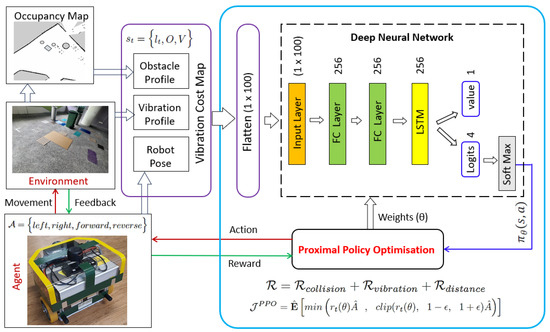
Figure 8.
Deep reinforcement learning architecture as per Proximal Policy Optimization.
4. Training and Evaluation
4.1. 1D CNN Training and Evaluation for Terrain Roughness Classification
To train the 1D CNN model, a supervised learning strategy was applied with our unique dataset, and we used an NVIDIA GeForce GTX 1080 Ti-powered workstation (GIGABYTE, Singapore) and the Tensorflow DL library. The following hyperparameters and values were finalized for high accuracy. Momentum with gradient descent was applied as an optimization strategy, and Adam (adaptive moment optimization) was selected as the optimizer. A learning rate of 0.001, with an exponential decay rate for the first moment (0.9) and second moment (0.999), was found to yield a faster and more stable learning process. The model converged with better accuracy at 100 epochs with a batch size of 32 after a few trial runs with varied values. The categorical cross-entropy loss function was used to compile the model. Statistical measure metrics (accuracy, precision, recall, and F1 score) were used for the model’s performance assessment, following the formula as in [68]. Table 1 lists the statistical measure results based on the evaluation dataset. Accordingly, the average accuracy of 97.5% was achieved for this terrain-induced vibration dataset. Next, a real-time test was conducted based on 500 samples collected from different places, which were not included for training or evaluation. The real-time test average prediction accuracy for the classes was found to be 97%, close to the evaluation result.

Table 1.
The 1D CNN model-based roughness level classification evaluation result.
An inference engine algorithm (Algorithm 2) was developed for the real-time prediction of the roughness class based on the temporal raw sensor data. This inference engine enables the 1D CNN to infer every new dataset in real time. A total of 128 temporal data (Data) and 9 features (Feature) are acquired, forming a new dataset [128 × 9] for every new class prediction. A temporary placeholder TempBuffer is used to collect the dataset, InfBuffer holds one complete dataset as input to the 1D CNN, and the model returns the predicted roughness class.
| Algorithm 2 Inference Engine 1D CNN |
|
4.2. Vibration Cost Mapping with Obstacle and Roughness Profiles
A virtual vibration cost map and the corresponding environment occupancy grid and real-time vibration cost scores are developed to evaluate the vibration cost mapping algorithm, as shown in Figure 9. A virtual floor area of 4 × 4 m is selected and randomly assigned obstacles and different vibration classes. As the robot’s footprint is 0.4 × 0.4 m, it is equivalent to 10 × 10 footprints. Four roughness classes are predicted and fused at every footprint, which are uniformly distributed, generating an effective vibration or roughness class per footprint. Here, the robot’s travel is directed by starting from position (0, 0), moving along the Y axis in a zig-zag pattern, to complete the roughness class prediction, vibration cost mapping, and uniform distribution. Two CSV files are generated as the output of this vibration cost mapping. An environment occupancy grid map shows the obstacle area and non-obstacle area, i.e., a static environment map. This is mainly for navigation and the avoidance of obstacles. The second CSV file, for the latest vibration cost score mapping, shows the undesired terrain roughness levels for the given workspace. This dynamic map is updated based on the 1D CNN-based real-time terrain prediction of the roughness classes. These two CSV files are the inputs for the RL agent for optimum path planning. The vibration cost map also represents the robot’s location, mentioning the X and Y coordinates in the map. This vibration cost map helps to visualize the given environment’s roughness level distribution, which fosters the selection of operational modes, maintenance, and rental strategies for professional service providers.
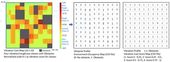
Figure 9.
Vibration cost map generating obstacle and vibration profile.
4.3. RL Policy Training and Evaluation
The training and evaluation of the proposed RL-based vibration-aware path planning system is conducted using two virtual environments named Virtual 1 and Virtual 2. For both environments, we select an area of 4 m × 4 m, and each movement (action) distance is taken to be the same as the footprint length, i.e., 0.4 m; hence, a matrix of 10 × 10 is used. Randomly selected obstacles and all four roughness/vibration classes are distributed in the virtual environment, as shown in Figure 10a and Figure 11a for the Virtual 1 and 2 environments, respectively, to evaluate the proposed framework. Figure 10b and Figure 11b show the vibration cost maps developed based on the proposed cost mapping algorithm. The information based on the vibration cost map, i.e., the obstacle profile, the vibration area, and the robot’s pose, is fed to the RL-based deep neural network for training. The training and evaluation details are given as follows.
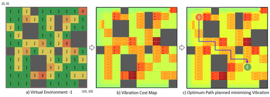
Figure 10.
Virtual environment 1: path planning with minimized vibration.
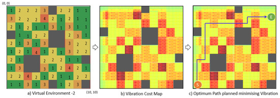
Figure 11.
Virtual environment 2: path planning with minimized vibration.
RLlib [69,70], the Tensorflow DL library [71], and the OpenAI Gym [72] toolkit are used to train and roll out the proposed RL model. RLlib, built on Ray [73], enables the optimized execution of RL frameworks. Its nested parallelism and resource-aware computation make training and evaluation more efficient. The hardware and software setups used for our training consisted of an Intel core-i7 CPU (Core Ultra 7 265K), RTX-3080 GPU (GeForce RTX 30 series) from NVIDIA, and Ubuntu 20.04 (Ubuntu 20.04 LTS).
We finalized the hyperparameters for the PPO after trial and error, as listed in Table 2, to ensure the optimum performance of the RL model. To decide how the agent considered future rewards over immediate ones, the discount factor was taken as 0.99, with a learning rate of 0.0001. A subset of the dataset, i.e., a mini-batch size of 128, was used to capture individual details. For the training process’ parallelization, the num_workers parameter was set to 5. For Stochastic Gradient Descent (SGD), the iteration (num_sgd_iter) parameter was chosen to be 16 per batch. To limit the surrogate loss function of PPO (Equation (7)) during training, the clip_param () parameter was used and set to 0.1. The and values for the LSTM model were set as 0.99 and 0.95, respectively. The number of episodes (agent–environment interactions from start to end) to decide termination was set to a maximum of 30 rewards or a maximum movement count of 125. The Virtual 1 training converged within 272,511 time steps for a reward of 125, and the Virtual 2 model took 1,339,115 time steps for the same reward.
Table 2.
Hyperparameter set for PPO training.
The model was rolled out after successful training for policy evaluation and real-time testing. Algorithm 3 was developed as the pseudocode detailing the steps involved in testing the model. By observing the environment (inputs), Algorithm 3 continuously updates the actions and communicates with the navigation stack of the agent (robot). Based on the updated rewards, the trained model provides the coordinates for the next movement (left, right, forward, reverse), targeting the destination, and loads the model’s weight. The robot’s navigation algorithms run on the ROS [74] noetic version and are localized via the Adaptive Monte Carlo Localization (AMCL) approach. Based on the algorithm’s output, the navigation stack triggers the robot’s movements from point to point towards the destination, considering the roughness level of the environment. For navigation, the robot is configured with the A* global planner [75] and DWA local planner [76]. After training, the model inferred the optimal values of each movement from the start to end locations, converging in a path that avoided obstacles and extremely rough areas, as shown in Figure 10c and Figure 11c.
| Algorithm 3 PPO Rollout |
|
In order to compare our model with the current path planning (A*) method, a performance index is formulated as per Equation (9). The A*-based path planning was developed based on obstacles and a short distance to the destination only, whereas, in the proposed RL-based system, the roughness levels of the terrain are also equally considered for path planning. Here, the movement parameter represents the model’s efficiency in finding the shortest path and counts the total number of movements triggered, and each movement has a footprint length of 0.4 m. The roughness score is the sum of the roughness index assigned earlier for each class, i.e., 1 to 4 for the very smooth to very rough classes. A higher roughness score indicates high maintenance costs and operational risks. We tested the above two virtual environments with the A* algorithm, comparing it with the proposed RL vibration-aware path planning model in terms of obtaining a short path and eliminating the vibration-prone rough areas, i.e., obtaining a low roughness score. There could be some scenarios in which, to avoid the rough area, the robot has to choose a longer path, which is not recommended because it equally affects the robot’s health due to prolonged operation. Hence, the ideal performance index (PI) is set as ≥ 1 to optimize the consideration of both the total movements and roughness score. The optimum paths chosen by these two algorithms (A* and RL) for the two virtual environments are illustrated in Figure 12. Accordingly, the performance indices for the Virtual 1 and 2 environments were 1.22 and 1.36, respectively. Here, the RL-based model could find the shortest path, as with A* (total movements), i.e., Virtual 1—12 moves and Virtual 2—17 moves. The total roughness scores for Virtual 1 were 22 and 18 for A* and RL, respectively. Similarly, for Virtual 2, they were 34 and 25 for A* and RL, respectively. Hence, the proposed vibration-aware RL-based path planning framework enables a path that minimizes the traversal through extremely rough areas, safeguarding the robot’s health and operations (see Table 3).
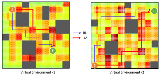
Figure 12.
Effectiveness of the proposed RL-based path model over the existing A* Algorithm.
Table 3.
Performance comparison (virtual) with existing A* path planning model.
5. Real-Time Field Case Studies and Validation
The effectiveness of the proposed vibration-aware RL-based path planning framework is evaluated using the virtual environments from the previous section. However, the framework’s performance needs to be validated in real-world scenarios to ensure real-time application. Hence, this section details two real-time experiments conducted by selecting two different environments and using the indoor mobile robot test platform described in the above section. The use of a single area representing all four roughness classes was one of the limitations in selecting the environment for real-time tests; hence, different types representing the typical terrain features were included, covering all classes for both experiments. This included hard bubbled mats, uniformly paved metal strips, and hard rubber strips of various thicknesses, kept at varied gaps. We used thin mica sheets to simulate the very smooth class. All floor objects were firmly fixed, with the floors similar to the built-in setup, and we ensured no shaking or breakage when the robot traveled on these objects during 2D occupancy grid mapping/scanning. A total of 4 m × 4 m was selected, and a 10 × 10 matrix was used for both case studies, similar to the virtual environments. A lobby hallway was chosen for the first case study (Real-Time Experiment 1) as the environment. This was a well-maintained concrete floor with a painted smooth finish, representing class 1 (very smooth). For the second case study (Real-Time Experiment 2), a pantry area was selected, where the floor was paved with small pebbles, which represented roughness class 2. Meanwhile, for the smooth class, thin mica sheets were used. We added sofas and large trash bins as obstacles. The testbed setups for Experiments 1 and 2 are shown in Figure 13a and Figure 14a, respectively.
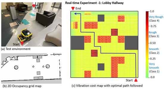
Figure 13.
Real-Time Experiment 1: environment setup and RL-based vibration-aware path.
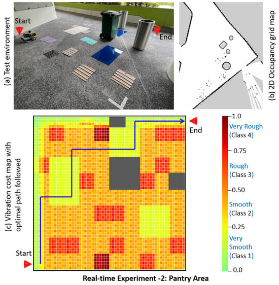
Figure 14.
Real-Time Experiment 2: environment setup and RL-based vibration-aware path.
First, the 2D occupancy grid map was generated for both environments, using the onboard RP LiDAR scanner and Cartographer SLAM algorithm, as shown in Figure 13b and Figure 14b, generating the obstacle profiles. Further, using the inference engine algorithm, the roughness classes of both environments were predicted by covering the whole 4 m × 4 m area in a zig-zag pattern. The robot’s linear speed was set at 0.08 m/s, and the IMU subscription rate was 100 Hz, as per the vibration cost mapping algorithm. Hence, a new roughness class was predicted at every 0.1 m, and the roughness levels were distributed per footprint as per the vibration cost mapping framework, as explained in the previous section, generating the vibration profile. Finally, the robot’s start and end point coordinates were assigned, generating the vibration cost map as input to the RL-based network. The PPO rollout generated a path, minimizing the traversal through the vibration prone-area and calculating the shortest path, as marked on the vibration cost map in Figure 13c and Figure 14c for Experiments 1 and 2, respectively.
Further, the efficiency of the proposed RL-based vibration-aware path planning algorithm compared to the existing A* path planning algorithm is assessed based on the two real-time experiments conducted. Accordingly, the performance indices (PIs) for Experiments 1 and 2 are 1.22 and 1.41, respectively. Here, the two models finished with the same number of movements for both experiments, i.e., 18. The roughness scores for Experiment 1 were 27 and 17 for A* and RL, respectively. Similarly, for Experiment 2, they were 38 and 27 for A* and RL, respectively, as given in Table 4. Hence, the effectiveness of the proposed R-based vibration-aware path planning framework is validated for real-time applications in real-world scenarios, being able to enhance the robot’s health and operational safety by eliminating the extremely rough areas of the floor. As the roughness levels of floors will change over time, the 1D CNN-based inference engine will keep the roughness classes updated. Based on the updated vibration cost map, this change in the environment will further update the RL policy, which will roll out updated path plans. This RL-based approach enhances the robot’s health irrespective of the changes in the roughness levels of the floor (environment) over time.
Table 4.
Performance comparison with existing A* path planning model.
6. Conclusions
Terrain-induced vibration is one of the critical sources of system deterioration in mobile robots, and the terrain features change based on the external and environmental conditions. Hence, in this work, we propose a new type of path planning strategy, adding extremely rough terrain features as a cost factor and a reinforcement learning-based path planning strategy for the self-learning of the changes in terrain features. The typical terrain features based on the vibration level generated are classified into four classes—very smooth, smooth, rough, and very rough—and classified by adopting a 1D CNN-based model for real-time prediction, yielding high accuracy (97%). A vibration cost mapping algorithm is developed to generate a vibration cost map containing the environment’s obstacle profile, the vibration profile, and the robot’s pose. It is used as input for the RL-based path planning framework to update the RL policy. An RL policy function is modeled for vibration state rewards as a Markov Decision Process (MDP), and a deep RL training model is developed to fine-tune the policy via Proximal Policy Optimization (PPO). An in-house-developed autonomous indoor robot is used as an RL agent. The proposed path planning framework, minimizing the traversal through anomalous terrain features, is evaluated using two virtual environments and validated by testing with two real-world environments. A comparison study with the existing path planning approach (A*) is conducted, and a performance index is proposed to measure the proposed framework’s effectiveness. The RL policy exhibits the same number of movements (total distance traveled) and significantly reduces the roughness score by choosing a path that avoids anomalous terrain areas.
The results demonstrate that the proposed RL approach to path planning for mobile robots, which avoids extremely rough areas, enhances the robot’s reliability and operational safety, reduces the maintenance costs, and facilitates corrective actions for terrain anomalies. In future work, we plan to test this model against other existing path planning methods, such as Dijkstra, RRT, and state lattice, for comparison purposes. Additionally, we aim to explore an RL-based, terrain-induced, vibration-aware path planning approach for outdoor mobile robots.
Author Contributions
Conceptualization, S.P. and M.R.E.; methodology, S.P. and B.F.G.; software, B.F.G. and S.P.; validation, S.P.; formal analysis, S.P., M.R.E. and B.F.G.; investigation, S.P. and M.R.E.; resources, M.R.E.; data, S.P. and B.F.G.; writing—original draft preparation, S.P.; supervision, M.R.E.; project administration, M.R.E.; funding acquisition, M.R.E. All authors have read and agreed to the published version of the manuscript.
Funding
This research was supported by the National Robotics Programme (NRP) under BAU, PANTHERA 2.0: Deployable Autonomous Pavement Sweeping Robot through Public Trials, Award No. M23NBK0065 and Ermine III: Deployable Reconfigurable Robots, Award No. M22NBK0054.
Data Availability Statement
The data presented in this study are available on request from the corresponding author.
Acknowledgments
Thanks to Pathmakumar Thejus for his inputs.
Conflicts of Interest
The authors declare no conflicts of interest.
References
- Community, M.R. Service Robotics Market Insights. Available online: https://marketresearchcommunity.com/service-robotics-market/?gad=1&gclid=Cj0KCQjwi7GnBhDXARIsAFLvH4lvApCX1lQFaV4UhpIVTnT1AtCyvwACN9j3RlxH_eZPlGZaUNdJKe8aAuRcEALw_wcB (accessed on 10 January 2023).
- Zhang, H.; Wang, W. A topological area coverage algorithm for indoor vacuuming robot. In Proceedings of the 2007 IEEE International Conference on Automation and Logistics, Jinan, China, 18–21 August 2007; pp. 2645–2649. [Google Scholar]
- Prabakaran, V.; Elara, M.R.; Pathmakumar, T.; Nansai, S. Floor cleaning robot with reconfigurable mechanism. Autom. Construct. 2018, 91, 155–165. [Google Scholar] [CrossRef]
- De Carvalho, R.N.; Vidal, H.; Vieira, P.; Ribeiro, M. Complete coverage path planning and guidance for cleaning robots. In Proceedings of the ISIE’97 IEEE International Symposium on Industrial Electronics, Guimaraes, Portugal, 7–11 July 1997; Volume 2, pp. 677–682. [Google Scholar]
- Kang, J.W.; Kim, S.J.; Chung, M.J.; Myung, H.; Park, J.H.; Bang, S.W. Path planning for complete and efficient coverage operation of mobile robots. In Proceedings of the 2007 International Conference on Mechatronics and Automation, Harbin, China, 5–8 August 2007; pp. 2126–2131. [Google Scholar]
- Saerbeck, M.; Bartneck, C. Perception of affect elicited by robot motion. In Proceedings of the 2010 5th ACM/IEEE International Conference on Human-Robot Interaction (HRI), Osaka, Japan, 2–5 March 2010; pp. 53–60. [Google Scholar]
- Le, A.V.; Ramalingam, B.; Gómez, B.F.; Mohan, R.E.; Minh, T.H.Q.; Sivanantham, V. Social density monitoring toward selective cleaning by human support robot with 3D based perception system. IEEE Access 2021, 9, 41407–41416. [Google Scholar]
- Rhim, S.; Ryu, J.C.; Park, K.H.; Lee, S.G. Performance evaluation criteria for autonomous cleaning robots. In Proceedings of the 2007 International Symposium on Computational Intelligence in Robotics and Automation, Jacksonville, FL, USA, 20–23 June 2007; pp. 167–172. [Google Scholar]
- Zheng, K.; Chen, G.; Cui, G.; Chen, Y.; Wu, F.; Chen, X. Performance metrics for coverage of cleaning robots with mocap system. In Intelligent Robotics and Applications, Proceedings of the 10th International Conference, ICIRA 2017, Wuhan, China, 16–18 August 2017, Proceedings, Part III 10; Springer: Berlin/Heidelberg, Germany, 2017; pp. 267–274. [Google Scholar]
- Khan, A.; Noreen, I.; Habib, Z. An energy efficient coverage path planning approach for mobile robots. In Proceedings of the Science and Information Conference; Springer: Berlin/Heidelberg, Germany, 2018; pp. 387–397. [Google Scholar]
- Mei, Y.; Lu, Y.H.; Hu, Y.C.; Lee, C.G. Energy-efficient motion planning for mobile robots. In Proceedings of the IEEE International Conference on Robotics and Automation, ICRA’04, New Orleans, LA, USA, 26 April–1 May 2004; Volume 5, pp. 4344–4349. [Google Scholar]
- Muthugala, M.V.J.; Vengadesh, A.; Wu, X.; Elara, M.R.; Iwase, M.; Sun, L.; Hao, J. Expressing attention requirement of a floor cleaning robot through interactive lights. Autom. Construct. 2020, 110, 103015. [Google Scholar] [CrossRef]
- Yan, Z.; Schreiberhuber, S.; Halmetschlager, G.; Duckett, T.; Vincze, M.; Bellotto, N. Robot perception of static and dynamic objects with an autonomous floor scrubber. Intell. Serv. Robot. 2020, 13, 403–417. [Google Scholar] [CrossRef]
- Song, H.; Li, A.; Wang, T.; Wang, M. Multimodal deep reinforcement learning with auxiliary task for obstacle avoidance of indoor mobile robot. Sensors 2021, 21, 1363. [Google Scholar] [CrossRef] [PubMed]
- Oleiwi, B.K.; Mahfuz, A.; Roth, H. Application of fuzzy logic for collision avoidance of mobile robots in dynamic-indoor environments. In Proceedings of the 2021 2nd International Conference on Robotics, Electrical and Signal Processing Techniques (ICREST), Dhaka, Bangladesh, 5–7 January 2021; pp. 131–136. [Google Scholar]
- Pookkuttath, S.; Rajesh Elara, M.; Sivanantham, V.; Ramalingam, B. AI-Enabled Predictive Maintenance Framework for Autonomous Mobile Cleaning Robots. Sensors 2021, 22, 13. [Google Scholar] [CrossRef]
- Pookkuttath, S.; Gomez, B.F.; Elara, M.R.; Thejus, P. An optical flow-based method for condition-based maintenance and operational safety in autonomous cleaning robots. Exp. Syst. Appl. 2023, 222, 119802. [Google Scholar] [CrossRef]
- Pookkuttath, S.; Veerajagadheswar, P.; Rajesh Elara, M. AI-Enabled Condition Monitoring Framework for Indoor Mobile Cleaning Robots. Mathematics 2023, 11, 3682. [Google Scholar] [CrossRef]
- Chng, G. Softbank Robotics Launches First Rent-a-Robot Offering for Cleaning Services in Singapore. Available online: https://www.techgoondu.com/2019/09/25/softbank-robotics-launches-first-rent-a-robot-offering-for-cleaning-services-in-singapore/ (accessed on 28 November 2021).
- Yakoubi, M.A.; Laskri, M.T. The path planning of cleaner robot for coverage region using Genetic Algorithms. J. Innov. Digit. Ecosyst. 2016, 3, 37–43. [Google Scholar] [CrossRef]
- Dakulović, M.; Horvatić, S.; Petrović, I. Complete coverage D* algorithm for path planning of a floor-cleaning mobile robot. IFAC Proc. Vol. 2011, 44, 5950–5955. [Google Scholar] [CrossRef]
- Hasan, K.M.; Reza, K.J. Path planning algorithm development for autonomous vacuum cleaner robots. In Proceedings of the 2014 International Conference on Informatics, Electronics & Vision (ICIEV), Dhaka, Bangladesh, 23–24 May 2014; pp. 1–6. [Google Scholar]
- Chong, W.M.; Goh, C.L.; Bau, Y.T. A practical framework for cleaning robots. In Proceedings of the 2011 Sixth International Conference on Bio-Inspired Computing: Theories and Applications, Penang, Malaysia, 27–29 September 2011; pp. 97–102. [Google Scholar]
- Schäfle, T.R.; Mohamed, S.; Uchiyama, N.; Sawodny, O. Coverage path planning for mobile robots using genetic algorithm with energy optimization. In Proceedings of the 2016 International Electronics Symposium (IES), Denpasar, Indonesia, 29–30 September 2016; pp. 99–104. [Google Scholar]
- Tick, D.; Rahman, T.; Busso, C.; Gans, N. Indoor robotic terrain classification via angular velocity based hierarchical classifier selection. In Proceedings of the 2012 IEEE International Conference on Robotics and Automation, St. Paul, MN, USA, 14–18 May 2012; pp. 3594–3600. [Google Scholar]
- Lee, H.; Chung, W. Terrain classification for mobile robots on the basis of support vector data description. Int. J. Precis. Eng. Manuf. 2018, 19, 1305–1315. [Google Scholar] [CrossRef]
- Bai, C.; Guo, J.; Zheng, H. Three-dimensional vibration-based terrain classification for mobile robots. IEEE Access 2019, 7, 63485–63492. [Google Scholar] [CrossRef]
- Dupont, E.M.; Moore, C.A.; Collins, E.G.; Coyle, E. Frequency response method for terrain classification in autonomous ground vehicles. Auton. Robot. 2008, 24, 337–347. [Google Scholar] [CrossRef]
- Weiss, C.; Tamimi, H.; Zell, A. A combination of vision-and vibration-based terrain classification. In Proceedings of the 2008 IEEE/RSJ International Conference on Intelligent Robots and Systems, Nice, France, 22–26 September 2008; pp. 2204–2209. [Google Scholar]
- Kiranyaz, S.; Avci, O.; Abdeljaber, O.; Ince, T.; Gabbouj, M.; Inman, D.J. 1D convolutional neural networks and applications: A survey. Mech. Syst. Signal Process. 2021, 151, 107398. [Google Scholar] [CrossRef]
- Eren, L.; Ince, T.; Kiranyaz, S. A generic intelligent bearing fault diagnosis system using compact adaptive 1D CNN classifier. J. Signal Process. Syst. 2019, 91, 179–189. [Google Scholar] [CrossRef]
- Ince, T.; Kiranyaz, S.; Eren, L.; Askar, M.; Gabbouj, M. Real-time motor fault detection by 1-D convolutional neural networks. IEEE Trans. Indust. Electr. 2016, 63, 7067–7075. [Google Scholar] [CrossRef]
- Abdeljaber, O.; Avci, O.; Kiranyaz, S.; Gabbouj, M.; Inman, D.J. Real-time vibration-based structural damage detection using one-dimensional convolutional neural networks. J. Sound Vib. 2017, 388, 154–170. [Google Scholar] [CrossRef]
- Wang, J.; Wang, D.; Wang, X. Fault diagnosis of industrial robots based on multi-sensor information fusion and 1D convolutional neural network. In Proceedings of the 2020 39th Chinese Control Conference (CCC), Shenyang, China, 27–29 July 2020; pp. 3087–3091. [Google Scholar]
- Dijkstra, E.W. A note on two problems in connexion with graphs. In Edsger Wybe Dijkstra: His Life, Work, and Legacy; Morgan & Claypool: San Rafael, CA, USA, 2022; pp. 287–290. [Google Scholar]
- Hart, P.E.; Nilsson, N.J.; Raphael, B. A formal basis for the heuristic determination of minimum cost paths. IEEE Trans. Syst. Sci. Cybern. 1968, 4, 100–107. [Google Scholar] [CrossRef]
- Stentz, A. The focussed d* algorithm for real-time replanning. In Proceedings of the IJCAI 1995, Montreal, QC, Canada, 20–25 August 1995; Volume 95, pp. 1652–1659. [Google Scholar]
- Koenig, S.; Likhachev, M. Improved fast replanning for robot navigation in unknown terrain. In Proceedings of the 2002 IEEE International Conference on Robotics and Automation (Cat. No. 02CH37292), Washington, DC, USA, 11–15 May 2002; Volume 1, pp. 968–975. [Google Scholar]
- Garrido, S.; Moreno, L.; Abderrahim, M.; Martin, F. Path planning for mobile robot navigation using voronoi diagram and fast marching. In Proceedings of the 2006 IEEE/RSJ International Conference on Intelligent Robots and Systems, Beijing, China, 9–13 October 2006; pp. 2376–2381. [Google Scholar]
- Dong, H.; Li, W.; Zhu, J.; Duan, S. The path planning for mobile robot based on Voronoi diagram. In Proceedings of the 2010 Third International Conference on Intelligent Networks and Intelligent Systems, Shenyang, China, 1–3 November 2010; pp. 446–449. [Google Scholar]
- Do, Q.H.; Nejad, H.T.N.; Yoneda, K.; Ryohei, S.; Mita, S. Vehicle path planning with maximizing safe margin for driving using Lagrange multipliers. In Proceedings of the 2013 IEEE Intelligent Vehicles Symposium (IV), Gold Coast City, Australia, 23–26 June 2013; pp. 171–176. [Google Scholar]
- Kavraki, L.E.; Svestka, P.; Latombe, J.C.; Overmars, M.H. Probabilistic roadmaps for path planning in high-dimensional configuration spaces. IEEE Trans. Robot. Autom. 1996, 12, 566–580. [Google Scholar] [CrossRef]
- Kuffner, J.J.; LaValle, S.M. RRT-connect: An efficient approach to single-query path planning. In Proceedings of the 2000 ICRA, Millennium Conference, IEEE International Conference on Robotics and Automation, Symposia Proceedings (Cat. No. 00CH37065), San Francisco, CA, USA, 24–28 April 2000; Volume 2, pp. 995–1001. [Google Scholar]
- Pivtoraiko, M.; Kelly, A. Generating near minimal spanning control sets for constrained motion planning in discrete state spaces. In Proceedings of the 2005 IEEE/RSJ International Conference on Intelligent Robots and Systems, Edmonton, AB, Canada, 2–6 August 2005; pp. 3231–3237. [Google Scholar]
- De Iaco, R.; Smith, S.L.; Czarnecki, K. Learning a lattice planner control set for autonomous vehicles. In Proceedings of the 2019 IEEE Intelligent Vehicles Symposium (IV), Paris, France, 9–12 June 2019; pp. 549–556. [Google Scholar]
- Elshamli, A.; Abdullah, H.A.; Areibi, S. Genetic algorithm for dynamic path planning. In Proceedings of the Canadian Conference on Electrical and Computer Engineering 2004 (IEEE Cat. No. 04CH37513), Fallsview Sheraton, NF, Canada, 2–5 May 2004; Volume 2, pp. 677–680. [Google Scholar]
- Brand, M.; Masuda, M.; Wehner, N.; Yu, X.H. Ant colony optimization algorithm for robot path planning. In Proceedings of the 2010 International Conference on Computer Design and Applications, Qinhuangdao, China, 25–27 June 2010; Volume 3, pp. V3–V436. [Google Scholar]
- Alam, M.S.; Rafique, M.U.; Khan, M.U. Mobile robot path planning in static environments using particle swarm optimization. arXiv 2020, arXiv:2008.10000. [Google Scholar]
- Tsuzuki, M.d.S.G.; de Castro Martins, T.; Takase, F.K. Robot path planning using simulated annealing. IFAC Proc. Vol. 2006, 39, 175–180. [Google Scholar] [CrossRef]
- Garaffa, L.C.; Basso, M.; Konzen, A.A.; de Freitas, E.P. Reinforcement learning for mobile robotics exploration: A survey. IEEE Trans. Neural Netw. Learn. Syst. 2021. Available online: https://ieeexplore.ieee.org/abstract/document/9612713?casa_token=LhfAyL1pX8cAAAAA:mVlP3LK_v68OX-rP_gEMVu5yryPmGN5lMdm5ynmq4ndKZqvfFuJVT5OriFkL_iOxRwAITIj-EziWQg (accessed on 26 February 2025). [CrossRef] [PubMed]
- Zhu, K.; Zhang, T. Deep reinforcement learning based mobile robot navigation: A review. Tsinghua Sci. Technol. 2021, 26, 674–691. [Google Scholar] [CrossRef]
- Xin, J.; Zhao, H.; Liu, D.; Li, M. Application of deep reinforcement learning in mobile robot path planning. In Proceedings of the 2017 Chinese Automation Congress (CAC), Jinan, China, 20–22 October 2017; pp. 7112–7116. [Google Scholar]
- Sun, H.; Zhang, W.; Yu, R.; Zhang, Y. Motion planning for mobile robots—Focusing on deep reinforcement learning: A systematic review. IEEE Access 2021, 9, 69061–69081. [Google Scholar] [CrossRef]
- Zhou, S.; Liu, X.; Xu, Y.; Guo, J. A deep Q-network (DQN) based path planning method for mobile robots. In Proceedings of the 2018 IEEE International Conference on Information and Automation (ICIA), Wuyishan, China, 11–13 August 2018; pp. 366–371. [Google Scholar]
- Yang, L.; Bi, J.; Yuan, H. Dynamic Path Planning for Mobile Robots with Deep Reinforcement Learning. IFAC-PapersOnLine 2022, 55, 19–24. [Google Scholar] [CrossRef]
- Sun, H.; Zhang, C.; Hu, C.; Zhang, J. Event-triggered reconfigurable reinforcement learning motion-planning approach for mobile robot in unknown dynamic environments. Eng. Appl. Artif. Intell. 2023, 123, 106197. [Google Scholar] [CrossRef]
- Bing, Z.; Lemke, C.; Morin, F.O.; Jiang, Z.; Cheng, L.; Huang, K.; Knoll, A. Perception-action coupling target tracking control for a snake robot via reinforcement learning. Front. Neurorobot. 2020, 14, 591128. [Google Scholar] [CrossRef]
- Schulman, J.; Wolski, F.; Dhariwal, P.; Radford, A.; Klimov, O. Proximal policy optimization algorithms. arXiv 2017, arXiv:1707.06347. [Google Scholar]
- Niroui, F.; Zhang, K.; Kashino, Z.; Nejat, G. Deep reinforcement learning robot for search and rescue applications: Exploration in unknown cluttered environments. IEEE Robot. Autom. Lett. 2019, 4, 610–617. [Google Scholar] [CrossRef]
- Min, H.; Xiong, X.; Wang, P.; Yu, Y. Autonomous driving path planning algorithm based on improved A* algorithm in unstructured environment. Proc. Inst. Mech. Eng. Part D J. Automob. Eng. 2021, 235, 513–526. [Google Scholar] [CrossRef]
- Hong, Z.; Sun, P.; Tong, X.; Pan, H.; Zhou, R.; Zhang, Y.; Han, Y.; Wang, J.; Yang, S.; Xu, L. Improved A-Star Algorithm for Long-Distance Off-Road Path Planning Using Terrain Data Map. ISPRS Int. J. Geo-Inform. 2021, 10, 785. [Google Scholar] [CrossRef]
- Zhang, X.; Wang, J.; Fang, Y.; Yuan, J. Multilevel humanlike motion planning for mobile robots in complex indoor environments. IEEE Trans. Autom. Sci. Eng. 2018, 16, 1244–1258. [Google Scholar] [CrossRef]
- Visca, M.; Bouton, A.; Powell, R.; Gao, Y.; Fallah, S. Conv1D energy-aware path planner for mobile robots in unstructured environments. In Proceedings of the 2021 IEEE International Conference on Robotics and Automation (ICRA), Xian, China, 30 May–5 June 2021; pp. 2279–2285. [Google Scholar]
- Pookkuttath, S.; Elara, M.R.; Mohan Rayguru, M.; Saldi, Z.S.; Sivanantham, V.; Ramalingam, B. Snail: An Eco-Friendly Autonomous Steam Mopping Robot for Cleaning and Disinfection of Floors. Mathematics 2023, 11, 1086. [Google Scholar] [CrossRef]
- Hess, W.; Kohler, D.; Rapp, H.; Andor, D. Real-time loop closure in 2D LIDAR SLAM. In Proceedings of the 2016 IEEE International Conference on Robotics and Automation (ICRA), Stockholm, Sweden, 16–21 May 2016; pp. 1271–1278. [Google Scholar]
- Schulman, J.; Moritz, P.; Levine, S.; Jordan, M.; Abbeel, P. High-dimensional continuous control using generalized advantage estimation. arXiv 2015, arXiv:1506.02438. [Google Scholar]
- Karlik, B.; Olgac, A.V. Performance analysis of various activation functions in generalized MLP architectures of neural networks. Int. J. Artif. Intell. Exp. Syst. 2011, 1, 111–122. [Google Scholar]
- Grandini, M.; Bagli, E.; Visani, G. Metrics for multi-class classification: An overview. arXiv 2020, arXiv:2008.05756. [Google Scholar]
- Liang, E.; Liaw, R.; Nishihara, R.; Moritz, P.; Fox, R.; Gonzalez, J.; Goldberg, K.; Stoica, I. Ray rllib: A composable and scalable reinforcement learning library. arXiv 2017, arXiv:1712.09381. [Google Scholar]
- Liang, E.; Liaw, R.; Nishihara, R.; Moritz, P.; Fox, R.; Goldberg, K.; Gonzalez, J.; Jordan, M.; Stoica, I. RLlib: Abstractions for distributed reinforcement learning. In Proceedings of the International Conference on Machine Learning, PMLR 2018, Stockholm, Sweden, 10–15 July 2018; pp. 3053–3062. [Google Scholar]
- Abadi, M.; Barham, P.; Chen, J.; Chen, Z.; Davis, A.; Dean, J.; Devin, M.; Ghemawat, S.; Irving, G.; Isard, M.; et al. Tensorflow: A system for large-scale machine learning. In Proceedings of the Osdi, Savannah, GA, USA, 2–4 November 2016; Volume 16, pp. 265–283. [Google Scholar]
- Brockman, G.; Cheung, V.; Pettersson, L.; Schneider, J.; Schulman, J.; Tang, J.; Zaremba, W. Openai gym. arXiv 2016, arXiv:1606.01540. [Google Scholar]
- Moritz, P.; Nishihara, R.; Wang, S.; Tumanov, A.; Liaw, R.; Liang, E.; Elibol, M.; Yang, Z.; Paul, W.; Jordan, M.I.; et al. Ray: A distributed framework for emerging {AI} applications. In Proceedings of the 13th {USENIX} Symposium on Operating Systems Design and Implementation ({OSDI} 18), Carlsbad, CA, USA, 8–10 October 2018; pp. 561–577. [Google Scholar]
- Quigley, M.; Conley, K.; Gerkey, B.; Faust, J.; Foote, T.; Leibs, J.; Wheeler, R.; Ng, A.Y. ROS: An open-source Robot Operating System. In Proceedings of the ICRA Workshop on Open Source Software, Kobe, Japan, 12–17 May 2009; Volume 3, p. 5. [Google Scholar]
- Marin-Plaza, P.; Hussein, A.; Martin, D.; Escalera, A.d.l. Global and local path planning study in a ROS-based research platform for autonomous vehicles. J. Adv. Transp. 2018, 2018, 6392697. [Google Scholar] [CrossRef]
- Fox, D.; Burgard, W.; Thrun, S. The dynamic window approach to collision avoidance. IEEE Robot. Autom. Mag. 1997, 4, 23–33. [Google Scholar] [CrossRef]
Disclaimer/Publisher’s Note: The statements, opinions and data contained in all publications are solely those of the individual author(s) and contributor(s) and not of MDPI and/or the editor(s). MDPI and/or the editor(s) disclaim responsibility for any injury to people or property resulting from any ideas, methods, instructions or products referred to in the content. |
© 2025 by the authors. Licensee MDPI, Basel, Switzerland. This article is an open access article distributed under the terms and conditions of the Creative Commons Attribution (CC BY) license (https://creativecommons.org/licenses/by/4.0/).