

The Application of Transformers with High-Temperature Superconducting Windings Considering the Skin Effect in Mobile Power Supply Systems

 , and
, and 
Abstract
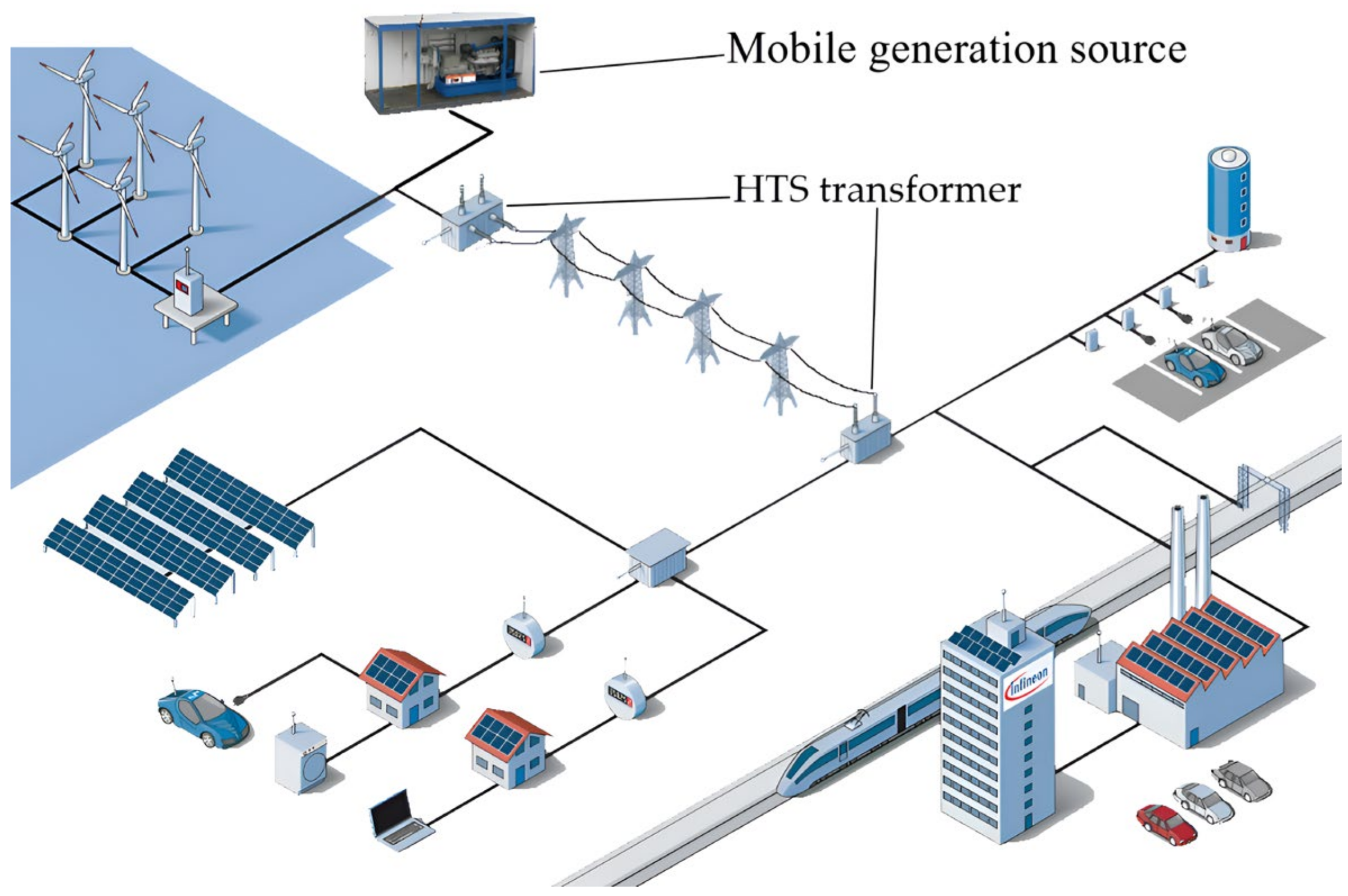
1. Introduction
- In practice, several methods are used to reduce the mass and dimensional parameters of transformer power equipment, including the following:
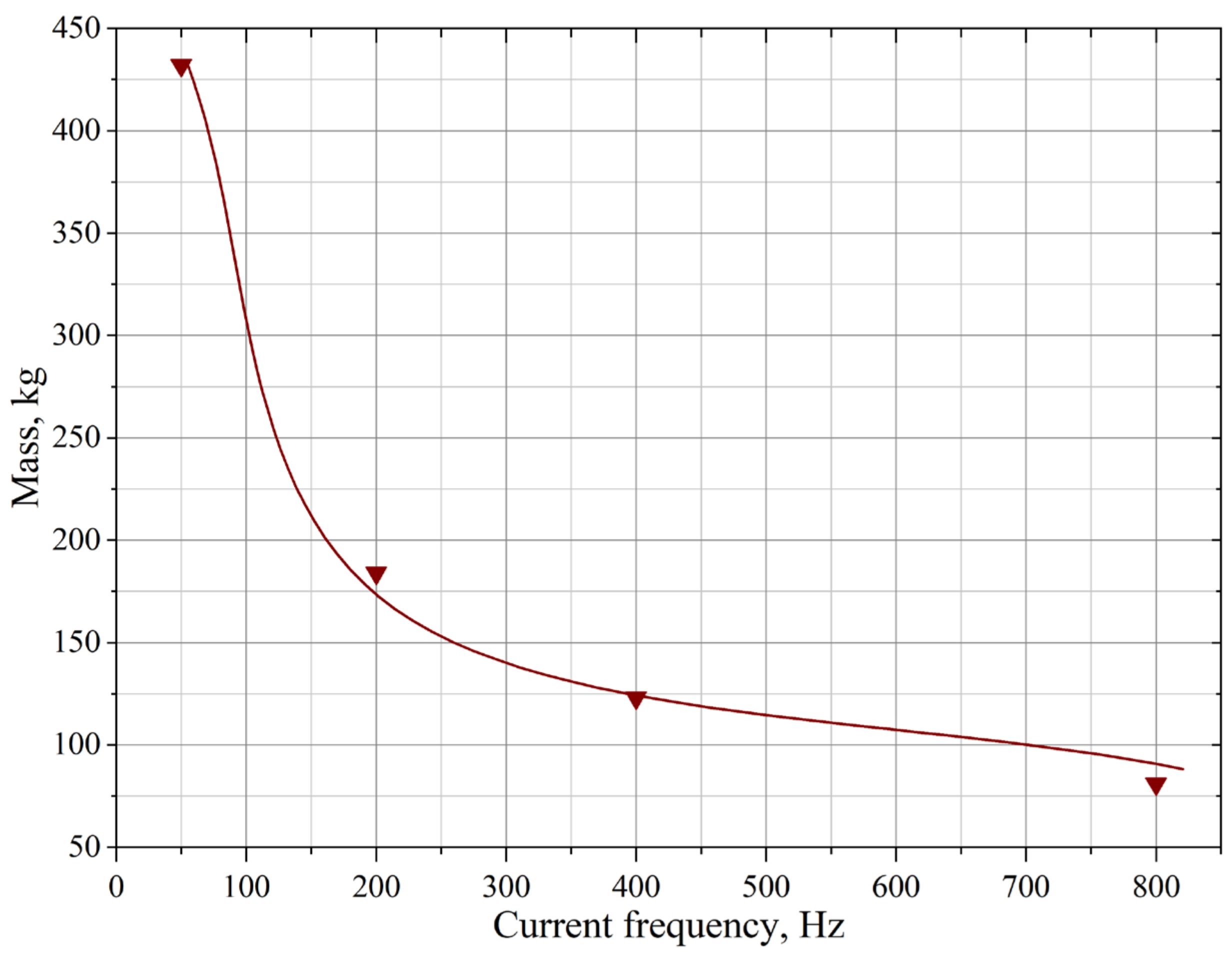
- The application of magnetic core material with high magnetic characteristics at an increase in frequency up to 800 Hz;
- The application of materials with high current density for transformer windings;
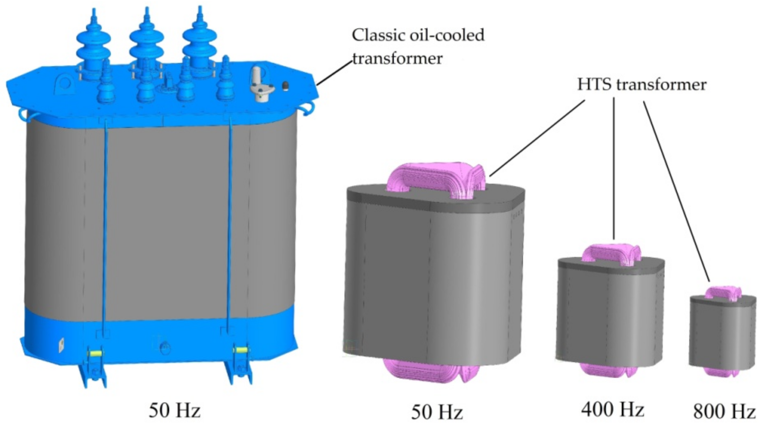
- The increase in the operating frequency in the electrical system.
2. Materials and Methods
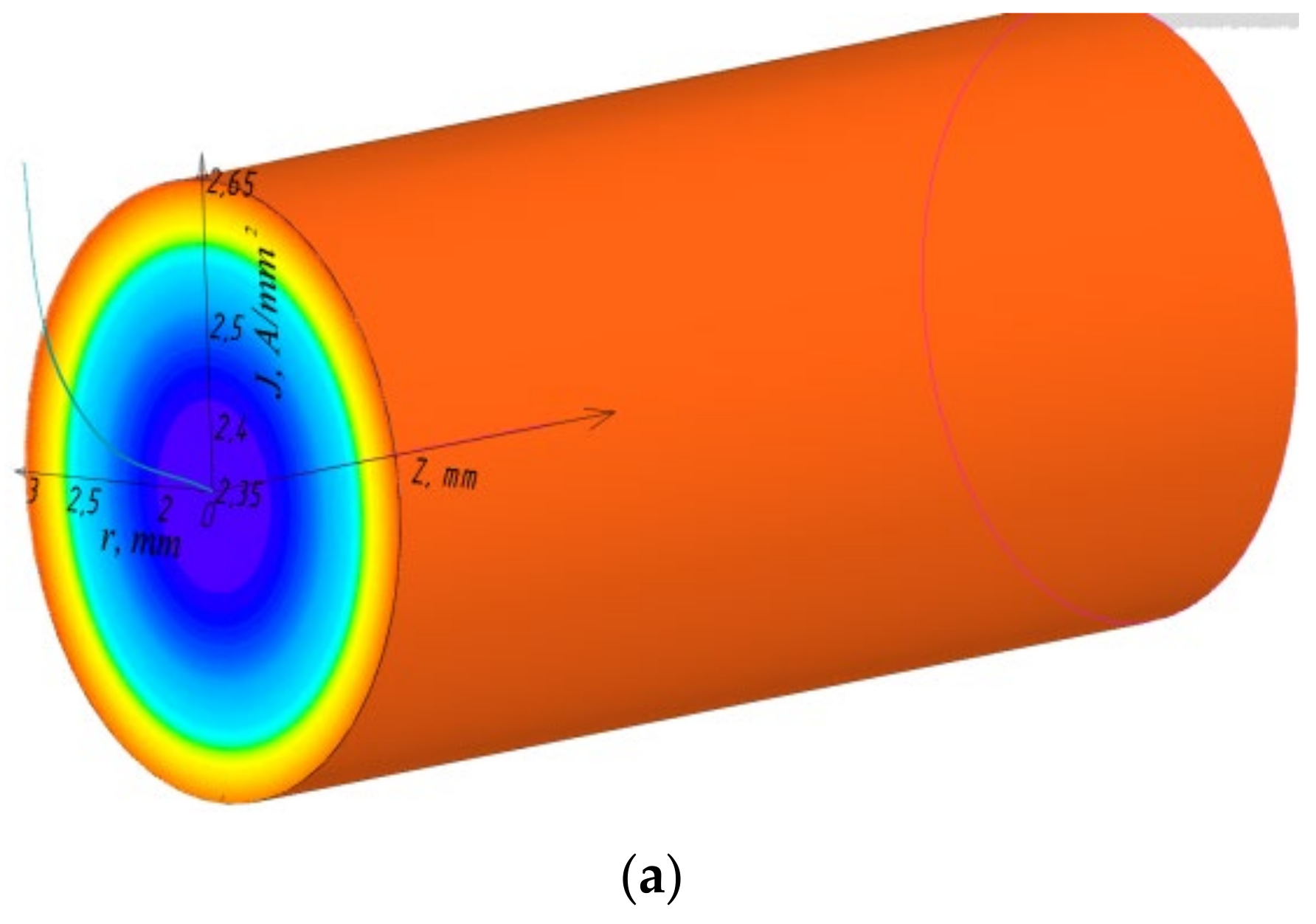
Investigation of HTS Transformers at High Frequencies
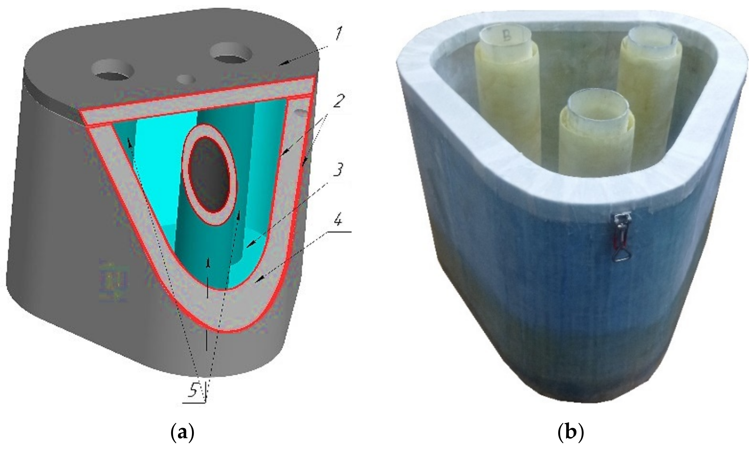
3. HTS Transformer Prototype
Dielectric Cryogenic Medium in the Form of Liquid Nitrogen
4. Discussion of Results
5. Conclusions
Author Contributions
Funding
Data Availability Statement
Conflicts of Interest
Abbreviations
| AdaBoost | Adaptive boosting |
| HTS | High-temperature superconducting |
| AMET | Asha Metallurgical Plant |
References
- Coufal, O. One Hundred and Fifty Years of Skin Effect. Appl. Sci. 2023, 13, 12416. [Google Scholar] [CrossRef]
- Zareba, M.; Szczegielniak, T.; Jablonski, P. Influence of the Skin and Proximity Effects on the Thermal Field in a System of Two Parallel Round Conductors. Energies 2023, 16, 6341. [Google Scholar] [CrossRef]
- Jablonski, P.; Zareba, M.; Szczegielniak, T.; Golebiowski, J. Influence of the Skin and Proximity Effects on the Thermal Field in Flat and Trefoil Three-Phase Systems with Round Conductors. Energies 2024, 17, 1713. [Google Scholar] [CrossRef]
- Jablonrski, P.; Kusiak, D.; Szczegielniak, T. Analytical-Numerical Approach to the Skin and Proximity Effect in Lines with Round Parallel Wires. Energies 2020, 13, 6716. [Google Scholar] [CrossRef]
- Ibrahim, M.; Pillay, P. Core loss prediction in electrical machine laminations considering skin effect and minor hysteresis loops. IEEE Trans. Ind. Appl. 2013, 49, 2061–2068. [Google Scholar] [CrossRef]
- de la Barriere, O.; Ferrara, E.; Magni, A.; Sola, A.; Ragusa, C.; Appino, C.; Fiorillo, F. Skin Effect and Losses in Soft Magnetic Sheets: From Low Inductions to Magnetic Saturation. IEEE Trans. Magn. 2023, 59, 6301211. [Google Scholar] [CrossRef]
- Arun, P. Practical Study of Mixed-Core High Frequency Power Transformer. Magnetism 2022, 2, 306–327. [Google Scholar] [CrossRef]
- Chan, H.L.; Cheng, K.W.E.; Sutanto, D. Calculation of inductances of high frequency air-core transformers with superconductor windings for DC-DC converters. IEE Proc. Electr. Power Appl. 2003, 150, 447–454. [Google Scholar] [CrossRef]
- Liu, G.; Zhang, G.; Liu, G.; Wang, H.; Jing, L. Experimental and numerical study of high frequency superconducting air-core transformer. Supercond. Sci. Technol. 2021, 34, 085011. [Google Scholar] [CrossRef]
- Pronto, A.G.; Maurício, A.; Pina, J.M. Magnetic properties measurement and discussion of an amorphous power transformer core at room and liquid nitrogen temperature. J. Phys. Conf. Ser. 2014, 507, 032018. [Google Scholar] [CrossRef]
- Arun, P. Application prospects of hybrid magnetic circuits in high frequency power transformers. IEEE J. Emerg. Sel. Top. Ind. Electron. 2022, 4, 1151–1158. [Google Scholar] [CrossRef]
- Vettoliere, A.; Granata, C. Superconducting Quantum Magnetometer Based on Flux Focusing Effect for High-Sensitivity Applications. Sensors 2024, 24, 3998. [Google Scholar] [CrossRef] [PubMed]
- Li, G.; Li, C.; Xin, Y.; Li, B. A Full-Wave High-Temperature Superconducting Rectifier Based on AC Field-Controlled Switches. IEEE Trans. Power Electron. 2024, 39, 16933–16942. [Google Scholar] [CrossRef]
- Wang, Y.; Zhong, X.; Chen, X. Influence of saturation levels on transformer equivalent circuit model. J. Electr. Eng. 2021, 72, 381–387. [Google Scholar] [CrossRef]
- Surdacki, P.; Wozniak, L. Influence of the HTS Winding Tape on Limiting the Transient Currents in Superconducting Transformers. Energies 2022, 15, 1688. [Google Scholar] [CrossRef]
- Yazdani-Asrami, M.; Gholamian, S.A.; Mirimani, S.M.; Adabi, J. Influence of field-dependent critical current on harmonic AC loss analysis in HTS coils for superconducting transformers supplying non-linear loads. Cryogenics 2021, 113, 103234. [Google Scholar] [CrossRef]
- Grilli, F.; Ashworth, S. Measuring transport AC losses in YBCO-coated conductor coils. Supercond. Sci. Technol. 2007, 20, 794–799. [Google Scholar] [CrossRef]
- Lee, S.; Petrykin, V.; Molodyk, A.; Samoilenkov, S.; Kaul, A.; Vavilov, A.; Vysotsky, V.; Fetisov, S. Development and production of second generation high Tc superconducting tapes at SuperOx and first tests of model cables. Supercond. Sci. Technol. 2014, 27, 044022. [Google Scholar] [CrossRef]
- Zhou, J.; Chan, W.; Quench, J.S. Detection Criteria for YBa2Cu3O7-δ Coils Monitored via a Distributed Temperature Sensor for 77 K Cases. IEEE Trans. Appl. Supercond. 2018, 28, 4703012. [Google Scholar] [CrossRef]
- Hu, M.; Zhou, Q.B.; Wang, X.; Tang, F.P.J.; Sheng, X.Y.; Jin, Z.J. Study of Liquid Nitrogen Insulation Characteristics for Superconducting Transformers. IEEE Trans. Appl. Supercond. 2022, 32, 5500305. [Google Scholar] [CrossRef]
- Hellmann, S.; Abplanalp, M.; Elschner, S.; Kudymow, A.; Noe, M. Current limitation experiments on a mva-class superconducting current limiting transformer. IEEE Trans. Appl. Supercond. 2019, 29, 5501706. [Google Scholar] [CrossRef]
- Lei, W.; Jiaojiao, W.; Tian, Y.; Xiaoning, H.; Fushou, X.; Yanzhong, L. Film boiling heat transfer prediction of liquid nitrogen from different geometry heaters. Int. J. Multiph. Flow 2020, 129, 103294. [Google Scholar] [CrossRef]
- Zabarilo, D.A. Features of the calculation of a high-frequency power transformer. Sci. Transp. Prog. 2013, 3, 29–35. [Google Scholar] [CrossRef] [PubMed]
- Zagirnyak, M.V.; Nevzlin, B.I. Functional interrelation of mass-dimensional and energy parameters of transformers. Part 1/News of higher educational institutions. Electromechanics 2004, 6, 47–52. [Google Scholar]
- Krivonosov, G.A. Calculation of transformer parameters. Electricity 2016, 6, 47–54. [Google Scholar]
- Malcolm, S.R. Experimental measurements of the skin effect and internal inductance at low frequencies. Acta Tech. 2015, 60, 51–69. [Google Scholar]
- Corcoran, J.; Nagy, P.B. Compensation of the Skin Effect in Low-Frequency Potential Drop Measurements. J. Nondestruct. Eval. 2016, 35, 58. [Google Scholar] [CrossRef]
- Peyne, A. Skin Effect, Proximity Effect and the Resistance of Circular and Rectangular Conductors. 2022. 41. Available online: https://www.researchgate.net/publication/363469604_Payne_Skin_Effect_Proximity_Effect_and_the_Resistance_of_Circular_and_Rectangular_Conductors_Issue_6 (accessed on 17 February 2025).
- ELCUT. Modelirovanie Elektromagnitnih_ Teplovih i Uprugih Polei Metodom Konechnih Elementov. Versiya 6.6. [Modeling of Electromagnetic, Thermal and Elastic Fields by the Finite Element Method. Version 6.6.]; St. Petersburg Press: St. Petersburg, FL, USA, 2023; p. 290. [Google Scholar]
- Orosz, T. FEM-Based Power Transformer Model for Superconducting and Conventional Power Transformer Optimization. Energies 2022, 15, 6177. [Google Scholar] [CrossRef]
- Sundaresh, A.; Väyrynen, J.I.; Lyanda-Geller, Y.; Rokhinson, L.P. Diamagnetic mechanism of critical current non-reciprocity in multilayered superconductors. Nat. Commun. 2023, 14, 1628. [Google Scholar] [CrossRef]
- PJSC “Ashinsky Metallurgical Plant” Magnetic Tape Pipelines Made of Soft Magnetic Amorphous Alloys and Soft Magnetic Composite Material (Nanocrystalline Alloy) Technical Specifications 14-123-215-2009. Available online: https://amet.ru/upload/main/TU%2014-123-215-2009.pdf?ysclid=m7hup7ztbk167789272 (accessed on 17 February 2025).
- Lenke, R.U.; Rohde, S.; Mura, F.; Doncker, R.W. Characterization of amorphous iron distribution transformer core for use in high-power medium-frequency applications. In Proceedings of the 2009 IEEE Energy Conversion Congress and Exposition, San Jose, CA, USA, 20–24 September 2009. [Google Scholar] [CrossRef]
- Kurita, N.; Nishimizu, A.; Kobayashi, C.; Tanaka, Y.; Yamagishi, A.; Ogi, M. Magnetic properties of simultaneously excited amorphous and silicon steel hybrid cores for higher efficiency distribution transformers. IEEE Trans. Magn. 2018, 54, 8400604. [Google Scholar] [CrossRef]
- An, S.; Im, H.; Kwon, Y.; Lee, J.; Jeong, J. Fine-Grained High-Permeability Fe73.5−xB9Si14Cu1Nb2·5Mx (M = Mo or W) Nanocrystalline Alloys with Co-Added Heterogeneous Transition Metal Elements. Metals 2024, 14, 1424. [Google Scholar] [CrossRef]
- Elgamli, E.; Anayi, F. Advancements in Electrical Steels: A Comprehensive Review of Microstructure, Loss Analysis, Magnetic Properties, Alloying Elements, and the Influence of Coatings. Appl. Sci. 2023, 13, 10283. [Google Scholar] [CrossRef]
- Azuma, D.; Ito, N.; Ohta, M. Recent progress in Fe-based amorphous and nanocrystalline soft magnetic materials. J. Magn. Magn. Mater. 2020, 501, 166373. [Google Scholar] [CrossRef]
- Suzuki, K.; Hujimori, H.; Hashimoto, K. Amorphous Metals; Masumoto, T.S., Ed.; Metallurgy: Moscow, Russia, 1987; p. 328. [Google Scholar]
- Pejush, C.S.; Youguang, G.; Hai, Y.L.; Jian, G.Z. Measurement modelling of rotational core loss of Fe-based amorphous magnetic material under 2-d magnetic excitation. IEEE Trans. Magn. 2021, 57, 8402008. [Google Scholar] [CrossRef]
- Nieroda, J.; Nieroda, J.; Kmita, G.; Kozupa, M.; Piela, S.; Rybak, A. The Use of Polyimide as a Bonding Material to Improve the Mechanical Stability, Magnetic and Acoustic Properties of the Transformer Core Based on Amorphous Steel. Polymers 2024, 16, 1840. [Google Scholar] [CrossRef]
- de la Barri, O.; Ferrara, E.; Magni, A.; Sola, A.; Ragusa, C.; Appino, C.; Fiorillo, F. A Practical Hybrid Hysteresis Model for Calculating Iron Core Losses in Soft Magnetic Materials. Energies 2024, 17, 2326. [Google Scholar] [CrossRef]
- Manusov, V.Z.; Galeev, R.G. Estimation of parameters of a superconducting hybrid transformer with a spatial magnetic system. Electricity 2024, 12, 15–26. [Google Scholar] [CrossRef]
- Kang, J.; Lee, H.; Kang, H. Dielectric Characteristics of Liquid Nitrogen According to the Electrode Material. J. Supercond. Nov. Magn. 2015, 28, 1167–1173. [Google Scholar] [CrossRef]
- Obukhov, S.G.; Beloglazkin, A.O. Engineering methodology for designing power supply systems for autonomous energy-efficient buildings based on renewable energy sources. Izv. Tomsk. Polytech. Univ. 2023, 334, 30–42. [Google Scholar] [CrossRef]
- Sarker, P.C.; Islam, R.M.; Guo, Y.; Zhu, J.; Lu, H.Y. State of art technologies for development of high frequency transformers with advanced magnetic materials. IEEE Trans. Appl. Supercond. 2019, 29, 7000111. [Google Scholar] [CrossRef]
- Oliveira, S.V.G.; Barbi, I. A three-phase step-up DC-DC converter with a three-phase high frequency transformer. In Proceedings of the IEEE International Symposium on Industrial Electronics, ISIE 2005, Dubrovnik, Croatia, 20–23 June 2005. [Google Scholar] [CrossRef]
- Nanato, N.; Adachi, T.; Yamanishi, T. Development of single-phase bi2223 high temperature superconducting transformer with protection system for high frequency and large current source. J. Phys. Conf. Ser. 2019, 1293, 012072. [Google Scholar] [CrossRef]
- Coombs, T.A.; Wang, Q.; Shah, A.; Hu, J.; Hao, L.; Patel, I.; Wei, H.; Wu, Y.; Coombs, T.; Wang, W. High-temperature superconductors and their large-scale applications. Nat. Rev. Electr. Eng. 2024, 1, 788–801. [Google Scholar] [CrossRef]
- Kondratowicz-Kucewicz, B.; Wojtasiewicz, G. The proposal of a transformer model with winding made of parallel 2g HTS tapes with transpositioners and its contact cooling system. IEEE Trans. Appl. Supercond. 2018, 28, 5500405. [Google Scholar] [CrossRef]
- Dai, S.; Ma, T.; Qiu, Q.; Zhu, Z.; Teng, Y.; Hu, L. Development of a 1250-kVA Superconducting Transformer and Its Demonstration at the Superconducting Substation. IEEE Trans. Appl. Supercond. 2016, 26, 5500107. [Google Scholar] [CrossRef]
- Manusov, V.Z.; Galeev, R.G.; Palagushkin, B.V. Superconducting Hybrid Transformer: No. 2023124635. Patent No. 2815169 C1, H01F 27/28, H01F 27/36, 12 March 2024. [Google Scholar]
- Volkov, E.P.; Jafarov, E.A.; Fleishman, L.S.; Jafarov, Z.E. Superconducting Transformer: No. 2015134312/07. Patent No. 2604056 C1, 10 December 2016. [Google Scholar]
- Jaroszynski, L.; Wojtasiewicz, G.; Janowski, T. Considerations of 2G HTS Transformer Temperature During Short Circuit. IEEE Trans. Appl. Supercond. 2018, 28, 5500205. [Google Scholar] [CrossRef]
- Lim, S.-H.; Park, M.-K.; Park, S.-H.; Chung, J.-W. Analysis on DC Fault Current Limiting Operation of Twice-Quench Trigger Type SFCL Using Transformer Considering Magnetizing Current and Current Limiting Reactor. Energies 2023, 16, 6299. [Google Scholar] [CrossRef]
- Tsotsopoulo, E.; Dysrko, A.; Hong, Q.; Elwakeel, A.; Elshiekh, M.; Yuan, W.; Booth, C.; Tzelepis, D. Modelling Fault Current Characterization of Superconducting Cable with High Temperature Superconducting Windings and Copper Stabilizer Layer. Energies 2020, 13, 6646. [Google Scholar] [CrossRef]
- Sadeghi, A.; Bonab, S.A.; Song, W.; Yazdani-Asrami, M. Short circuit analysis of a fault-tolerant current-limiting high temperature superconducting transformer in a power system in presence of distributed generations. Superconductivity 2024, 9, 100085. [Google Scholar] [CrossRef]


| Parameter | Value | |
|---|---|---|
| Rated power, kVA | 100 | |
| Number of phases | 3 | |
| Winding connection | Δ/Yn-0 | |
| Cryostat material | Expanded polystyrene | |
| Dielectric medium | Liquid nitrogen | |
| Operating temperature, K | 77 | |
| Current frequency, Hz | 50, 200, 400, 800 | |
| Winding parameters | ||
| Winding parameter | HV winding | LV winding |
| Rated voltage, V | 10,000 | 400 |
| HTS tape width, mm | 4 × 0.1 | 12 × 0.1 |
| Insulation | Polyamide varnish | |
| Rated current, A | 3.7 | 162.5 |
| Current density (плoтнocть тoкa), A/mm2 | 9.25 | 135 |
| Magnetic core parameters | ||
| Amorphous magnetic core 1B | ||
| Alloying elements | B, Si, P, C, Co, Ba | |
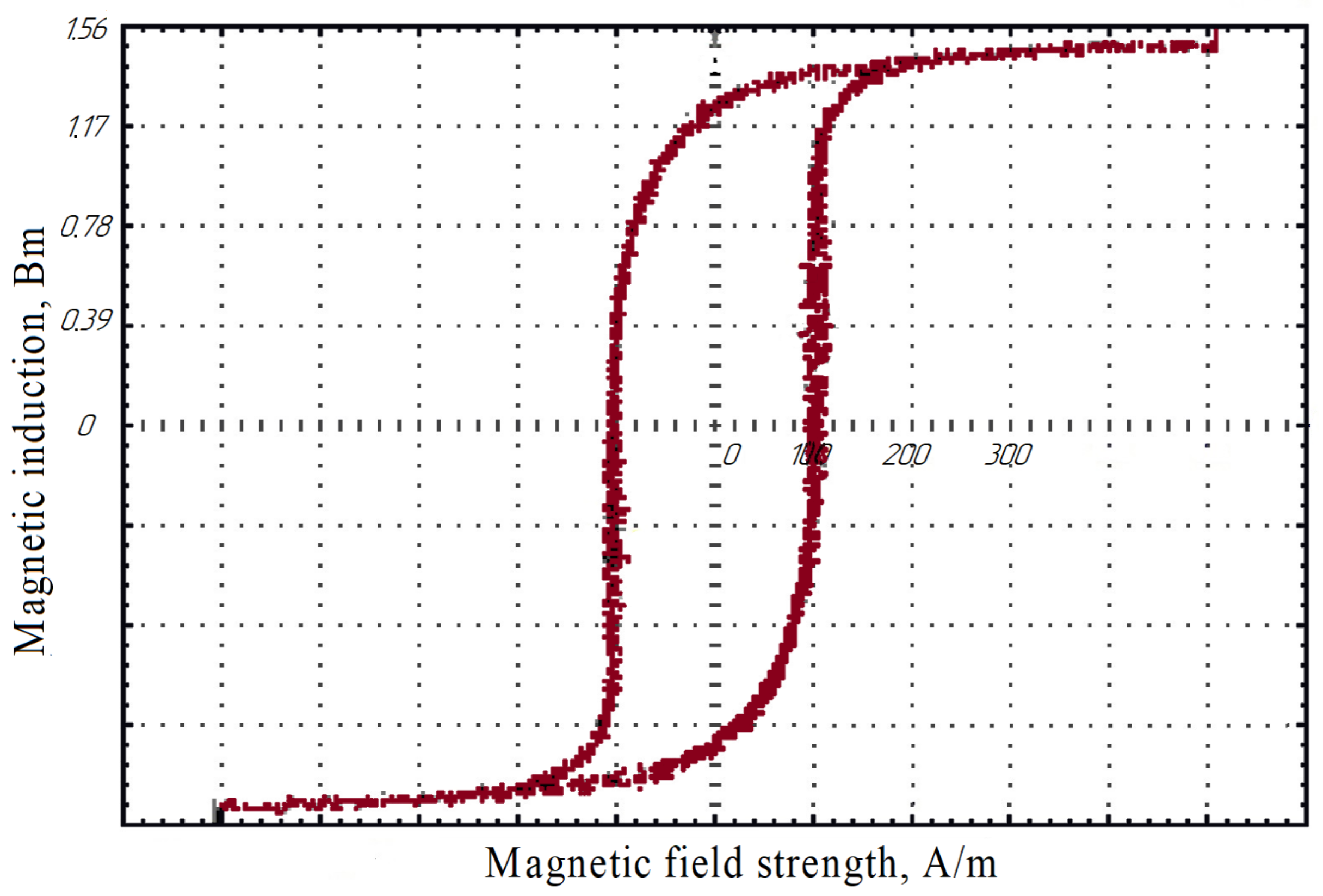
| Saturation induction, Bm | 1.57 | |
| f (network frequency), Hz | 50 | 200 | 400 | 800 |
| d (leg diameter), m | 0.135 | 0.095 | 0.08 | 0.067 |
| Gst (magnetic core weight), kg | 432 | 184 | 123 | 81 |
| Et (turn EMF), V | 3.382 | 6.701 | 9.623 | 13.32 |
| wLV (number of secondary turns) | 68 | 34 | 24 | 17 |
| wHV (number of primary turns) | 2945 | 1473 | 1040 | 737 |
| Φm (magnetic flow), Wb | 0.015 | 0.008 | 0.005 | 0.004 |
| Ph (hysteresis losses), W | 171 | 297 | 396 | 532 |
| Ped (eddy current losses), W | 25 | 223 | 594 | 1595 |
| Pid (core losses), W | 196 | 521 | 990 | 2127 |
| Parameter | Value |
|---|---|
| Molar mass, g·mol−1 | 28.01 |
| Liquid phase density at saturation, kg·m−3 | 807.4 |
| Gas phase density at saturation, kg·m−3 | 4 604 |
| Speed of sound in liquid phase, m·s−1 | 860 |
| Volumetric expansion of liquid (77.3 K, 0.10 MPa) into gas (293 K, 0.10 MPa) | 1:694 |
| Relative permittivity of liquid nitrogen | 1.46 |
| Relative permittivity of gaseous nitrogen | 1.00 |
| Electrical resistivity, Ohm·m | >1 × 10¹⁶ |
| Surface tension, N·m−1 | 8.9 × 10⁻³ |
| Dynamic viscosity, Pa·s | 1.65 × 10⁻⁴ |
| Thermal conductivity, W·m−1·K−1 | 0.14 |
| Heat capacity, J·g−1·K−1 | 2.04 |
| Enthalpy of vaporization, J·g−1 | 199.3 |
| Critical point at 3.35 MPa, K | 126.21 |
| Triple point at 0.0125 MPa, K | 63.1 |
Disclaimer/Publisher’s Note: The statements, opinions and data contained in all publications are solely those of the individual author(s) and contributor(s) and not of MDPI and/or the editor(s). MDPI and/or the editor(s) disclaim responsibility for any injury to people or property resulting from any ideas, methods, instructions or products referred to in the content. |
© 2025 by the authors. Licensee MDPI, Basel, Switzerland. This article is an open access article distributed under the terms and conditions of the Creative Commons Attribution (CC BY) license (https://creativecommons.org/licenses/by/4.0/).
Share and Cite
Manusov, V.; Zicmane, I.; Galeev, R.; Beryozkina, S.; Safaraliev, M. The Application of Transformers with High-Temperature Superconducting Windings Considering the Skin Effect in Mobile Power Supply Systems. Mathematics 2025, 13, 821. https://doi.org/10.3390/math13050821
Manusov V, Zicmane I, Galeev R, Beryozkina S, Safaraliev M. The Application of Transformers with High-Temperature Superconducting Windings Considering the Skin Effect in Mobile Power Supply Systems. Mathematics. 2025; 13(5):821. https://doi.org/10.3390/math13050821
Chicago/Turabian StyleManusov, Vadim, Inga Zicmane, Ratmir Galeev, Svetlana Beryozkina, and Murodbek Safaraliev. 2025. "The Application of Transformers with High-Temperature Superconducting Windings Considering the Skin Effect in Mobile Power Supply Systems" Mathematics 13, no. 5: 821. https://doi.org/10.3390/math13050821
APA StyleManusov, V., Zicmane, I., Galeev, R., Beryozkina, S., & Safaraliev, M. (2025). The Application of Transformers with High-Temperature Superconducting Windings Considering the Skin Effect in Mobile Power Supply Systems. Mathematics, 13(5), 821. https://doi.org/10.3390/math13050821