

URAdv: A Novel Framework for Generating Ultra-Robust Adversarial Patches Against UAV Object Detection

 , , ,
, , ,
Abstract
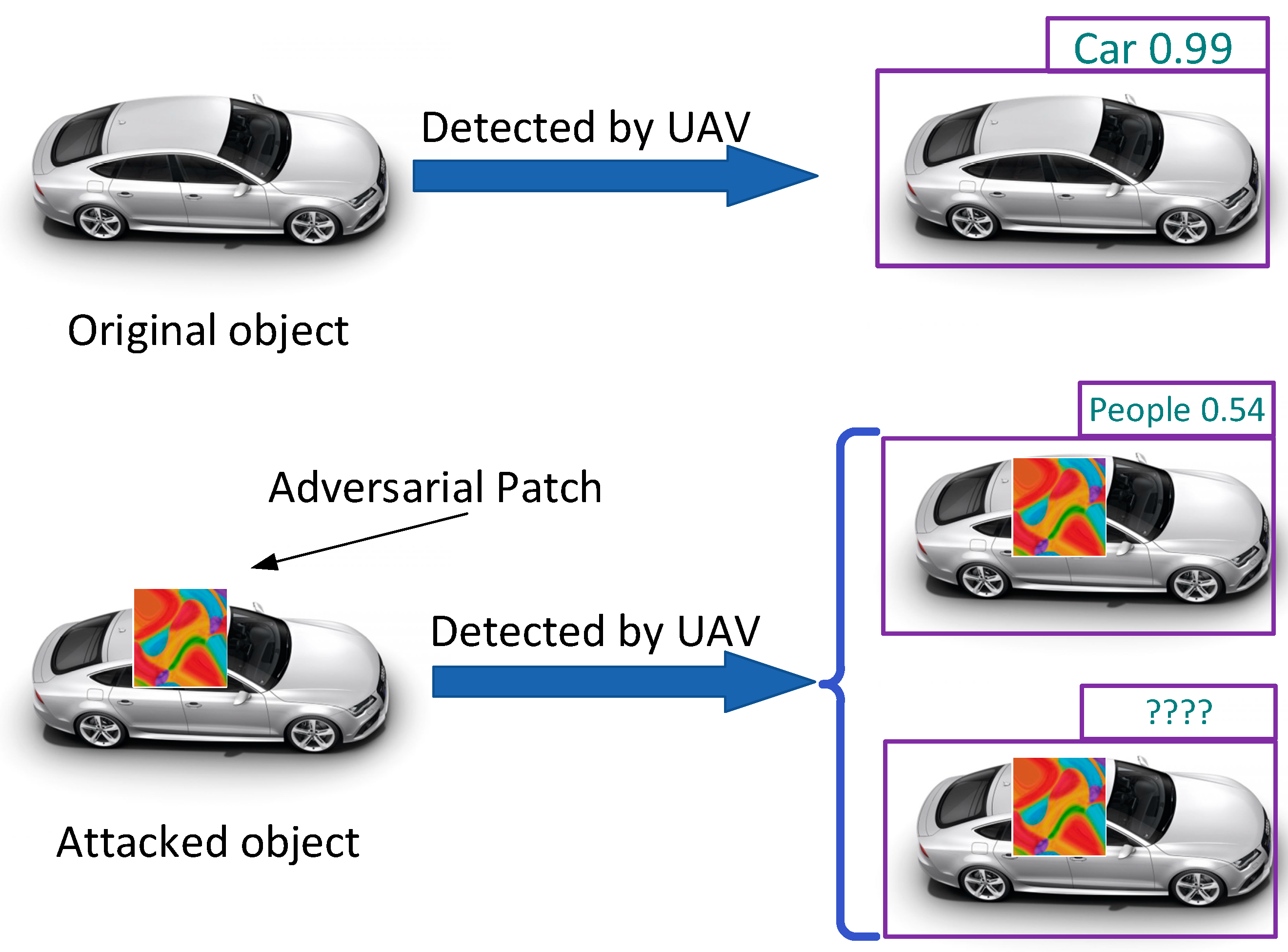
1. Introduction
- (a)
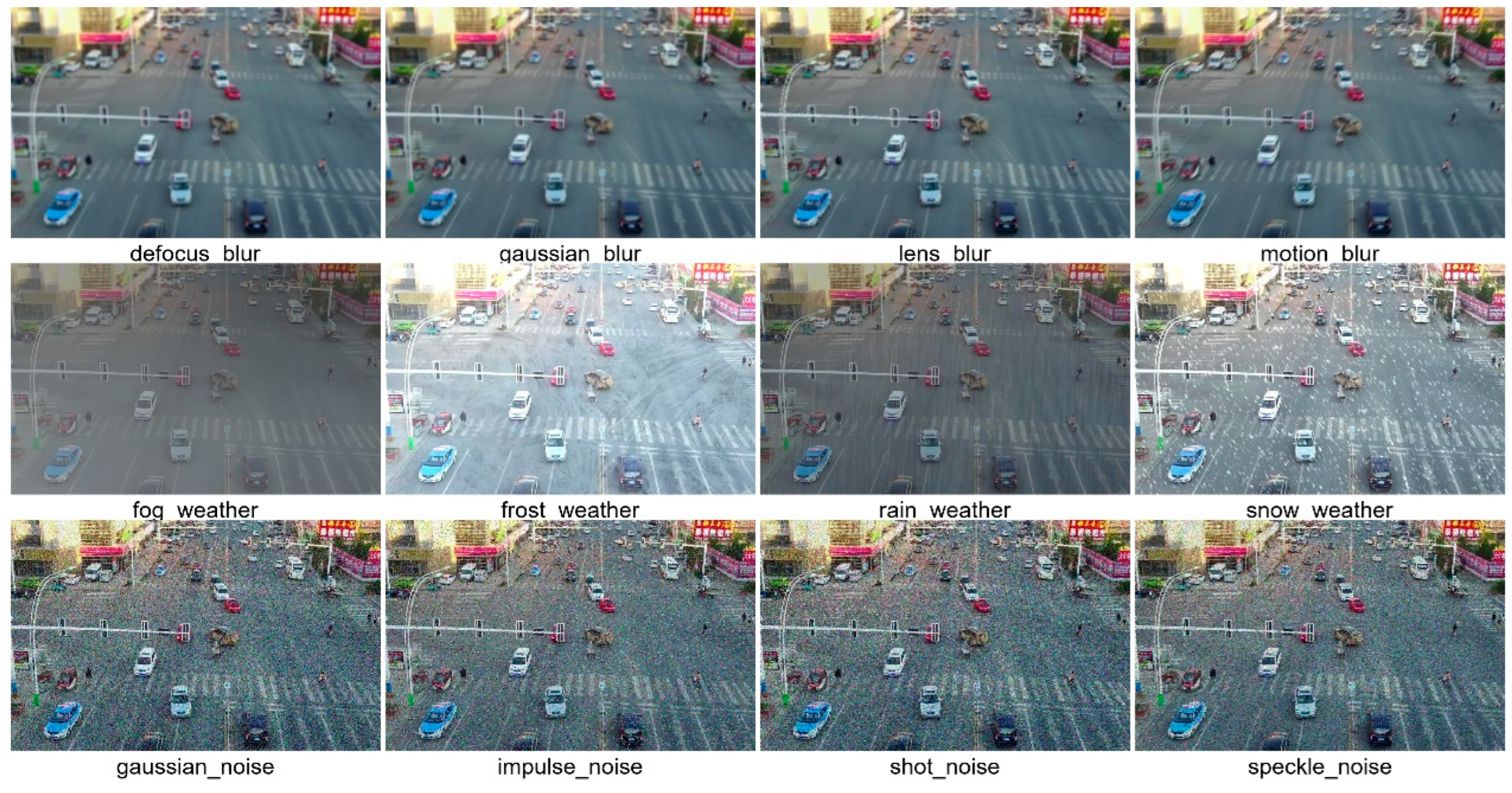
- We constructed the VisDrone-13 dataset based on VisDrone2019, which more closely resembles the complexities of the physical environment. We trained more transferable adversarial patches using this dataset, which simulates 13 types of real-world perturbations that could be encountered during UAV data acquisition, thereby enhancing the robustness of adversarial patches in complex UAV scenarios.
- (b)
- We integrated a local corruption model into the training process of adversarial patches, primarily to account for reflections under strong lighting conditions and shadows under occlusion. This approach aligns the decision boundary of the surrogate model more closely with the classification boundary encountered in real-world scenarios, thereby enhancing the transferability of adversarial attacks.
- (c)
- We implemented a nested optimization approach to address the discontinuity in adversarial attacks due to altitude variations during UAV flights. By strategically overlaying patches, this method enables continuous attacks at various distances within a predefined range.
2. Background and Related Work
2.1. Application of UAV Object Detection
2.2. Physical Adversarial Attacks
3. Threat Model
4. Constructed VisDrone-13 Dataset
4.1. Benchmark of Dataset
4.2. Complicating Factors
4.3. Construction of the VisDrone-13 Dataset
5. Methods
5.1. Adversarial Patch Transformation
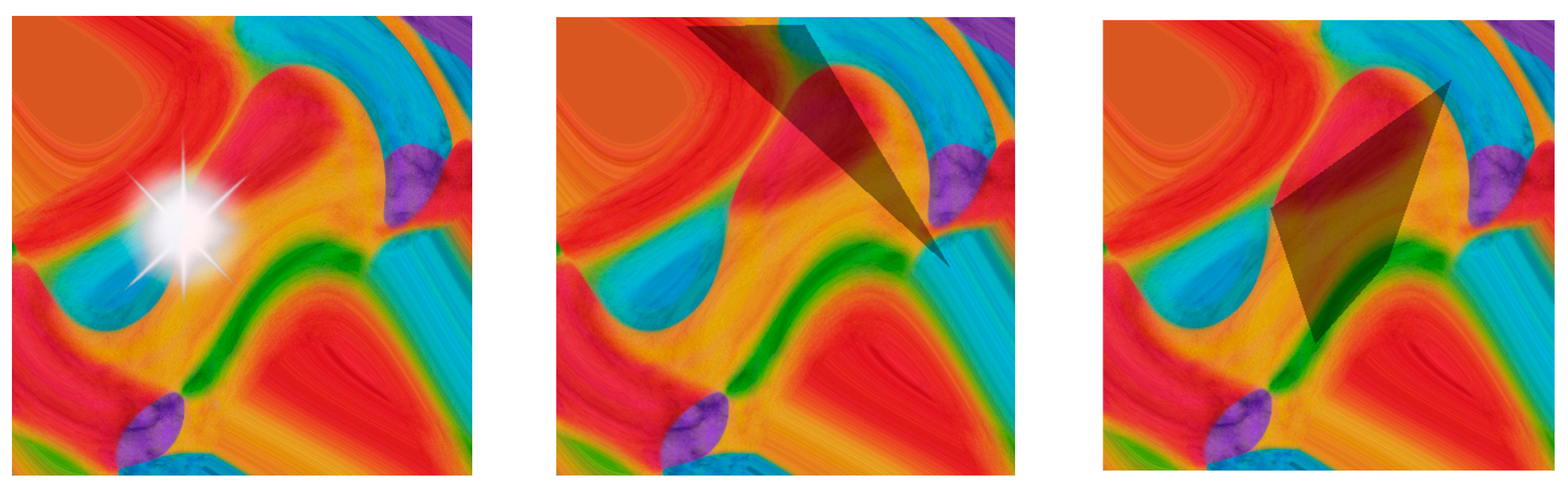
5.1.1. Perturbation of Light and Shadow
| Algorithm 1. Generation of Light Spots on Patch |
| Input: max_radius: Maximum radius of the light spots. P: Patch. Output: combined_image: Image with light spot. |
|
5.1.2. Nested Optimization
5.1.3. Printability and Scene Matching
5.1.4. Patch Transformations
| Algorithm 2. Patch Transformations |
|
5.2. Loss Function
5.3. Generation of Adversarial Patch
6. Experiments
6.1. Setup of the Experiments
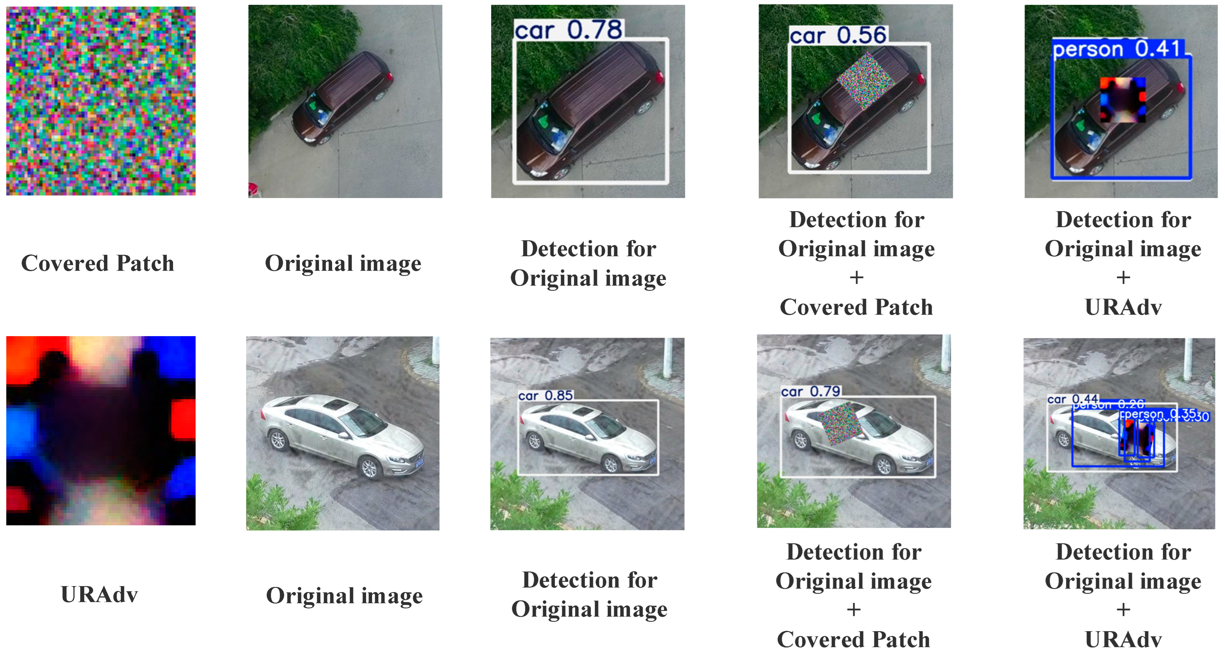
- (a)
- The decline in recognition accuracy is caused by the adversarial patches (URAdv) rather than the general interference resulting from ordinary object occlusion.
- (b)
- The patches generated using YOLOv5-Small can be effectively transferred to YOLOv5-Large to achieve a similar adversarial effect. That is, URAdv has good transferability to gray-box attacks.
6.2. Results and Evaluation
6.2.1. Evaluation of Effectiveness
6.2.2. Evaluation of Transferability

6.2.3. Parameter Sensitivity Analysis
6.2.4. Comparison of Initialization Methods
- (a)
- Initialization Based on Image Features: Utilize intermediate layer features from the target detection model to initialize the patch. For instance, extract activation features of the model for a specific category or use the average of image examples from the target category to initialize the patch, thereby aligning it more closely with the target category.
- (b)
- Initialization Based on Adversarial Examples: Employ existing adversarial examples as the initial patch. These examples, having undergone optimization, can serve as an effective starting point.
7. Conclusions
Author Contributions
Funding
Data Availability Statement
Conflicts of Interest
References
- Lee, S.J.; Rho, M. Multimodal Deep Learning Applied to Classify Healthy and Disease States of Human Microbiome. Sci. Rep. 2022, 12, 824. [Google Scholar] [CrossRef] [PubMed]
- Kuang, Q.; Wu, J.; Pan, J.; Zhou, B. Real-Time Uav Path Planning for Autonomous Urban Scene Reconstruction. In Proceedings of the 2020 IEEE International Conference on Robotics and Automation (ICRA), Paris, France, 31 May–31 August 2020; pp. 1156–1162. [Google Scholar]
- Chen, H.; Lu, P. Computationally Efficient Obstacle Avoidance Trajectory Planner for Uavs Based on Heuristic Angular Search Method. In Proceedings of the 2020 IEEE/RSJ International Conference on Intelligent Robots and Systems (IROS), Las Vegas, NV, USA, 24 October 2020–24 January 2021; pp. 5693–5699. [Google Scholar]
- Katta, S.S.; Viegas, E.K. Towards a Reliable and Lightweight Onboard Fault Detection in Autonomous Unmanned Aerial Vehicles. In Proceedings of the 2023 IEEE International Conference on Robotics and Automation (ICRA), London, UK, 29 May–2 June 2023; pp. 1284–1290. [Google Scholar]
- Jun, M.; Lilian, Z.; Xiaofeng, H.; Hao, Q.; Xiaoping, H. A 2dgeoreferenced Map Aided Visual-Inertial System for Precise Uav Localization. In Proceedings of the 2022 IEEE/RSJ International Conference on Intelligent Robots and Systems (IROS), Kyoto, Japan, 23–27 October 2022; pp. 4455–4462. [Google Scholar]
- Duan, R.; Mao, X.; Qin, A.K.; Chen, Y.; Ye, S.; He, Y.; Yang, Y. Adversarial Laser Beam: Effective Physical-World Attack Todnns in a Blink. In Proceedings of the IEEE/CVF Conference on Computer Vision and Pattern Recognition, Nashville, TN, USA, 20–25 June 2021; pp. 16062–16071. [Google Scholar]
- Zhong, Y.; Liu, X.; Zhai, D.; Jiang, J.; Ji, X. Shadows Can Be Dangerous: Stealthy and Effective Physical-World Adversarial Attack by Natural Phenomenon. In Proceedings of the 2022 IEEE/CVF Conference on Computer Vision and Pattern Recognition (CVPR), New Orleans, LA, USA, 18–24 June 2022; pp. 15345–15354. [Google Scholar]
- Wang, D.; Yao, W.; Jiang, T.; Li, C.; Chen, X. RFLA: A Stealthy Reflected Light Adversarial Attack in the Physical World. In Proceedings of the 2023 IEEE/CVF International Conference on Computer Vision (ICCV), Paris, France, 1–6 October 2023; pp. 4455–4465. [Google Scholar]
- Wei, X.; Guo, Y.; Yu, J. Adversarial Sticker: A Stealthy Attack Method in the Physical World. IEEE Trans. Pattern Anal. Mach. Intell. 2023, 45, 2711–2725. [Google Scholar] [CrossRef] [PubMed]
- Du, A.; Chen, B.; Chin, T.-J.; Law, Y.W.; Sasdelli, M.; Rajasegaran, R.; Campbell, D. Physical Adversarial Attacks on an Aerial Imagery Object Detector. In Proceedings of the IEEE/CVF Winter Conference on Applications of Computer Vision, Waikoloa, HI, USA, 3–8 January 2022; pp. 1796–1806. [Google Scholar]
- Lian, J.; Mei, S.; Zhang, S.; Ma, M. Benchmarking Adversarial Patch against Aerial Detection. IEEE Trans. Geosci. Remote Sens. 2022, 60, 1–16. [Google Scholar] [CrossRef]
- Shen, H.; Zong, Q.; Tian, B. Voxel-Based Localization and Mapping for Multirobot System in GPS-Denied En. IEEE Trans. Ind. Electron. 2022, 69, 10333–10342. [Google Scholar] [CrossRef]
- Zhou, H.; Yao, Z.; Zhang, Z. An online multi-robot SLAM system based on LiDAR/UWB fusion. IEEE Sens. J. 2021, 22, 2530–2542. [Google Scholar] [CrossRef]
- Yang, C.; Huang, Z.; Wang, N. QueryDet: Cascaded Sparse Query for Accelerating High-Resolution Small Object Detection. In Proceedings of the IEEE/CVF Conference on Computer Vision and Pattern Recognition, New Orleans, LA, USA, 18–24 June 2022; pp. 13668–13677. [Google Scholar]
- Du, B.; Huang, Y.; Chen, J. Adaptive Sparse Convolutional Networks with Global Context Enhancement for Faster Object Detection on Drone Images. In Proceedings of the IEEE/CVF Conference on Computer Vision and Pattern Recognition, Vancouver, BC, Canada, 17–24 June 2023; pp. 13435–13444. [Google Scholar]
- Qi, G.; Zhang, Y.; Wang, K.; NealMazur, Y.L.; Malaviya, D. Small Object Detection Method Based on Adaptive Spatial Parallel Convolution and Fast Multi-Scale Fusion. Remote Sens. 2022, 14, 420. [Google Scholar] [CrossRef]
- Deng, S.; Li, S.; Xie, K.; Song, W.; Liao, X.; Hao, A.; Qin, H. A Global-Local Self-Adaptive Network for Drone-View Object Detection. IEEE Trans. Image Process. 2021, 30, 3. [Google Scholar] [CrossRef] [PubMed]
- Thys, S.; Ranst, W.; Goedemé, T. Fooling Automated Surveillance Cameras: Adversarial Patches to Attack Person Detection. In Proceedings of the IEEE/CVF Conference on Computer Vision and Pattern Recognition (CVPR) Workshops, Long Beach, CA, USA, 15–20 June 2019. [Google Scholar]
- Wang, Y.; Lv, H.; Kuang, X. Towards a Physical-World Adversarial Patch for Blinding Object Detection Models. Inf. Sci. 2021, 556, 459–471. [Google Scholar] [CrossRef]
- Wei, X.; Yu, J.; Huang, Y. Physically Adversarial Infrared Patches with Learnable Shapes and Locations. In Proceedings of the IEEE/CVF Conference on Computer Vision and Pattern Recognition, Vancouver, BC, Canada, 17–24 June 2023; pp. 12334–12342. [Google Scholar]
- Maesumi, A.; Zhu, M.; Wang, Y.; Chen, T.; Wang, Z.; Bajaj, C. Learning Transferable 3D Adversarial Cloaks for Deep Trained Detectors. arXiv 2021, arXiv:2104.11101. [Google Scholar]
- Zhang, Y.; Zhang, Y.; Qi, J. Adversarial Patch Attack on Multi-Scale Object Detection for UAV Remote Sensing Images. Remote Sens. 2022, 14, 5298. [Google Scholar] [CrossRef]
- Lu, M.; Li, Q.; Chen, L. Scale-Adaptive Adversarial Patch Attack for Remote Sensing Image Aircraft Detection. Remote Sens. 2021, 13, 4078. [Google Scholar] [CrossRef]
- Guesmi, A.; Hanif, M.A.; Shafique, M. Advrain: Adversarial Raindrops to Attack Camera-Based Smart Vision Systems. Information 2023, 14, 634. [Google Scholar] [CrossRef]
- Zhu, P.; Wen, L.; Du, D.; Bian, X.; Fan, H.; Hu, Q.; Ling, H. Detection and Tracking Meet Drones Challenge. IEEE Trans. Pattern Anal. Mach. Intell. 2022, 44, 7380–7399. [Google Scholar] [CrossRef]
- Hendrycks, D.; Dietterich, T. Benchmarking Neural Network Robustness to Common Corruptions and Perturbations. arXiv 2019, arXiv:1903.12261. [Google Scholar]
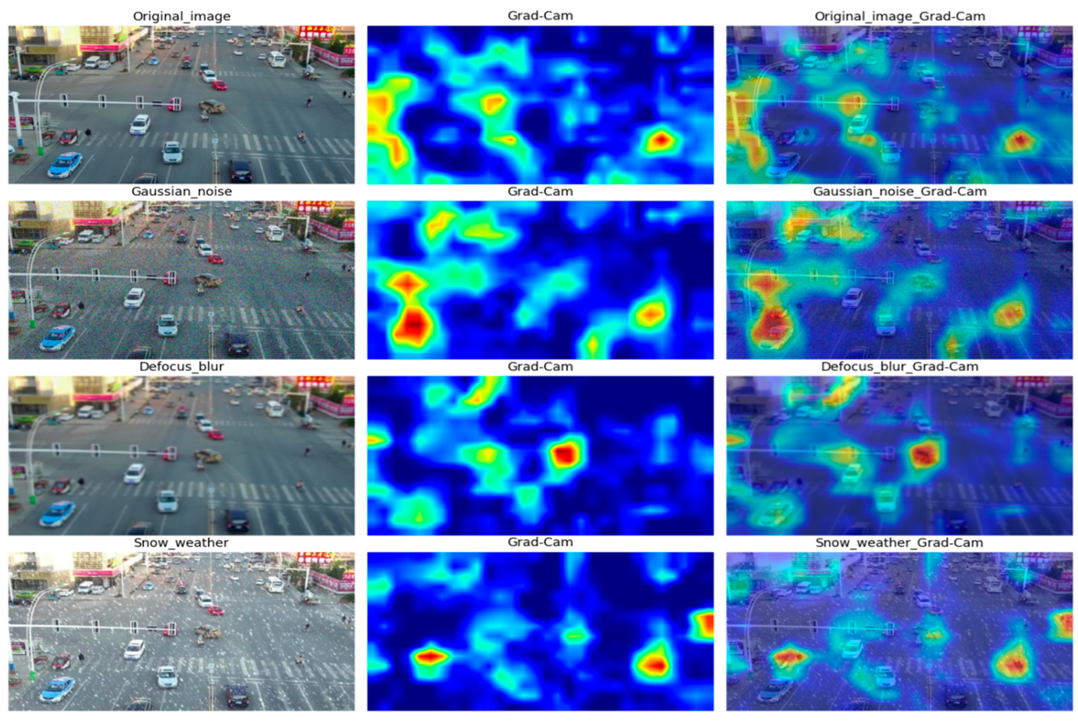
- Selvaraju, R.R. Grad-CAM: Visual Explanations from Deep Networks via Gradient-Based Localization. Int. J. Comput. Vis. 2020, 128, 336–359. [Google Scholar] [CrossRef]
- Yufeng, L.; Fengyu, Y.; Qi, L.; Jiangtao, L.; Chenhong, C. Light Can Be Dangerous: Stealthy and Effective Physical-World Adversarial Attack by Spot Light. Comput. Secur 2023, 132, 103345. [Google Scholar]
- Zhang, Y.; Gong, Z.; Wen, H.; Hu, X.; Xia, X.; Jiang, H.; Zhong, P. Pattern Corruption-Assisted Physical Attacks against Object Detection in UAV Remote Sensing. IEEE J. Sel. Top. Appl. Earth Obs. Remote Sens. 2024, 17, 12931–12944. [Google Scholar] [CrossRef]
- Liu, T.; Yang, C.; Liu, X. RPAU: Fooling the Eyes of Uavs via Physical Adversarial Patches. IEEE Trans. Intell. Transp. Syst. 2023, 25, 2586–2598. [Google Scholar] [CrossRef]
- Zeng, B.; Gao, L.; Zhang, Q.; Li, C.; Song, J.; Jing, S. Boosting Adversarial Attacks by Leveraging Decision Boundary Information. arXiv 2023, arXiv:2303.05719. [Google Scholar]
- Shrestha, S.; Pathak, S.; Viegas, E.K. Towards a Robust Adversarial Patch Attack against Unmanned Aerial Vehicles Object Detection. In Proceedings of the IEEE/RSJ International Conference on Intelligent Robots and Systems (IROS), Detroit, MI, USA, 1–5 October 2023; pp. 3256–3263. [Google Scholar]
- Lin, T.Y.; Maire, M.; Belongie, S.; Hays, J.; Perona, P.; Ramanan, D.; Dollár, P.; Zitnick, C.L. Microsoft Coco: Common Objects in Context. In Computer Vision–ECCV 2014: 13th European Conference, Zurich, Switzerland, 6–12 September 2014, Proceedings, Part V 13; Springer International Publishing: Cham, Switzerland, 2014; pp. 740–755. [Google Scholar]
- Sharif, M.; Bhagavatula, S.; Bauer, L. Accessorize to a Crime: Real and Stealthy Attacks on State-of-the-Art Face Recognition. In Proceedings of the 2016 Acm Sigsac Conference on Computer and Communications Security, Vienna, Austria, 24–28 October 2016; pp. 1528–1540. [Google Scholar]


| Methods | Muti-Target | Dynamic Environment | Transferability |
|---|---|---|---|
| Thys et al. [18] | × | × | × |
| Wang et al. [19] | × | × | √ |
| Zhang et al. [22] | √ | √ | × |
| AdvRain [24] | × | √ | × |
| Wang et al. [8] | √ | × | √ |
| URAdv (Ours) | √ | √ | √ |
| Constructions | Types | Levels | Proportion | |
|---|---|---|---|---|
| Normal | Original images | 10% | ||
| Weather Changes | Rain | 1~3 | Random (0~30%) | 30% |
| Snow | Random (0~30%) | |||
| Fog | Random (0~30%) | |||
| Frost | Random (0~30%) | |||
| Camera Blur | Lens_blur | Random (0~30%) | 30% | |
| Gaussian_blur | Random (0~30%) | |||
| Defocus_blur | Random (0~30%) | |||
| Motion_blur | Random (0~30%) | |||
| Environment noise | Impulse_noise | Random (0~30%) | 30% | |
| Shot_noise | Random (0~30%) | |||
| Gaussian_noise | Random (0~30%) | |||
| Speckle_noise | Random (0~30%) | |||
| Type | Expression | Description |
|---|---|---|
| Ambient Brightness | contrast, brightness, noise: Uniform random number | |
| Optical Distortions | α: Amplitude of distortion β: Amplitude of movement | |
| Shooting Angles | ʘ: Rotation angle |
| Parameters | Value | Parameters | Value |
|---|---|---|---|
| Batch_size | 10 | Sgd_momentum | 0.937 |
| Epoch | 400 | Weight decay | 0.001 |
| Learning_rate | (0.001, 0.1) | IOU_threshold | 0.4 |
| Parameters | Value | Parameters | Value |
|---|---|---|---|
| Contrast | [0.5, 1.5] | Rotation | [−30°, 30°] |
| Brightness | [−0.2, 0.2] | Scale | [0.7, 1] |
| Noise | [−0.1, 0.1] | Spotlight_size | [0.5w, 1.5w] |
Disclaimer/Publisher’s Note: The statements, opinions and data contained in all publications are solely those of the individual author(s) and contributor(s) and not of MDPI and/or the editor(s). MDPI and/or the editor(s) disclaim responsibility for any injury to people or property resulting from any ideas, methods, instructions or products referred to in the content. |
© 2025 by the authors. Licensee MDPI, Basel, Switzerland. This article is an open access article distributed under the terms and conditions of the Creative Commons Attribution (CC BY) license (https://creativecommons.org/licenses/by/4.0/).
Share and Cite
Xi, H.; Ru, L.; Tian, J.; Lu, B.; Hu, S.; Wang, W.; Luan, X. URAdv: A Novel Framework for Generating Ultra-Robust Adversarial Patches Against UAV Object Detection. Mathematics 2025, 13, 591. https://doi.org/10.3390/math13040591
Xi H, Ru L, Tian J, Lu B, Hu S, Wang W, Luan X. URAdv: A Novel Framework for Generating Ultra-Robust Adversarial Patches Against UAV Object Detection. Mathematics. 2025; 13(4):591. https://doi.org/10.3390/math13040591
Chicago/Turabian StyleXi, Hailong, Le Ru, Jiwei Tian, Bo Lu, Shiguang Hu, Wenfei Wang, and Xiaohui Luan. 2025. "URAdv: A Novel Framework for Generating Ultra-Robust Adversarial Patches Against UAV Object Detection" Mathematics 13, no. 4: 591. https://doi.org/10.3390/math13040591
APA StyleXi, H., Ru, L., Tian, J., Lu, B., Hu, S., Wang, W., & Luan, X. (2025). URAdv: A Novel Framework for Generating Ultra-Robust Adversarial Patches Against UAV Object Detection. Mathematics, 13(4), 591. https://doi.org/10.3390/math13040591