Article

Nonlinear Dynamic Modeling of Rotor-Bearing Systems with Combined Support Considering Coupled Motion: Numerical and Experimental Studies

1
School of Mechanical Engineering and Automation, Northeastern University, Shenyang 110819, China
2
Guangxi Key Laboratory of Automobile Components and Vehicle Technology, Guangxi University of Science and Technology, Liuzhou 545006, China
3
Foshan Graduate School of Innovation, Northeastern University, Foshan 528312, China
4
National Key Laboratory of Particle Transport and Separation Technology, Tianjin 300180, China
*
Author to whom correspondence should be addressed.
Mathematics 2025, 13(22), 3694; https://doi.org/10.3390/math13223694
Submission received: 3 October 2025 / Revised: 7 November 2025 / Accepted: 10 November 2025 / Published: 18 November 2025
(This article belongs to the Section C2: Dynamical Systems)

Abstract

The elastic support structure is widely employed in rotor systems and has an important influence on the nonlinear vibration of such systems. Nevertheless, coupled motion between elastic supports and bearings has not been taken into account, and the coupling effect of these two components on rotor dynamics remains insufficiently elucidated. Therefore, this work presents a bearing force model considering the motion of the elastic support. Subsequently, this work presents a new rotor-bearing dynamics model, in which the coupled motion between elastic supports and bearings is explicitly accounted for. Moreover, the coupling effect of elastic supports and bearings is systematically investigated through analyses of frequency–amplitude responses, waterfall plots, contact loads of bearings, operational deflection shape, and bifurcation diagrams. To further reveal this coupling effect, the nonlinear vibration behaviors of the rotor-bearing system with elastic support are analyzed under different bearing initial clearances. Finally, the experiments on rotor test rigs with and without elastic supports are conducted to validate the accuracy of the proposed dynamic model. Both simulation and experimental results indicate that elastic supports mitigate the nonlinear vibration of the rotor-bearing system; additionally, elastic support could reduce the bearing reaction forces and contact loads. Moreover, elastic supports alter the operational deflection shape of the rotor-bearing system.

1. Introduction

Rotor-bearing systems (RBSs) serve as important dynamic components in a broad range of rotating machinery, including aero-engines, gas turbines, and steam turbines. During actual operation, rotor systems are subject to numerous nonlinear factors, which induce nonlinear vibration behaviors [1,2,3,4,5]. For instance, the rubbing force can be induced by rotor-casing contact, and the nonlinear bearing forces, etc. [6,7,8,9]. These nonlinear factors interact with each other, leading to complex nonlinear vibration behaviors in the rotor system [10,11,12,13]. Especially after the rotor adopts a combined support, the elastic support structure causes significant changes in the vibration of the rotor and the bearing. However, existing research on elastic support-rotor-bearing systems is not in-depth, and the effect of elastic support on the nonlinearity of the bearing is also unclear. Therefore, analyzing rotor-bearing systems’ nonlinear vibration response under elastic support has theoretical and practical significance.
In recent years, a number of scholars have studied nonlinear vibration behaviors of rotor-bearing systems. Taking nonlinear bearing forces into account, scholars have studied the vibration characteristics of Jeffcott rotors [14,15,16]. Considering misalignment and unbalance faults, the nonlinear vibration characteristics of rotor systems were investigated [17,18,19]. Kim et al. and Cao et al. have separately investigated the nonlinear dynamic behaviors of cracked rotor systems and blade-rotor assemblies, respectively [20,21,22]. Furthermore, many scholars have adopted the lumped mass method or the finite element method to establish rotor dynamics models [23,24,25,26]. These methods can not only better consider the influence of rotor weight and size on its elastic deformation but also bring in nonlinear factors, including bearings, cages, and squeeze film dampers, into the rotor system. Some scholars have established the static models of rolling bearings considering multiple degrees of freedom [27,28,29]. The bearing reaction forces acting on the shaft are imposed on the nonlinear rotor system to investigate the effects of variations in bearing parameters on the system’s nonlinear dynamic behaviors. Building on the static model of the bearing, some other scholars have established quasi-static and dynamic models of rolling bearings [30,31,32]. The above-mentioned research has carried out meaningful work within the realm of nonlinear vibration of rotor-bearing systems. However, these studies have not focused on the changes in nonlinear vibration characteristics when the rotor system is influenced by elastic supports.
The support structure in the rotor system typically consists of bearings (i.e., rolling bearings and sliding bearings) and elastic support structures (e.g., squirrel cage, elastic ring, squeeze film damper, etc.). Firstly, for rolling bearings, they have nonlinear factors such as bearing clearance, Raceway defects, Hertz contact force, and variable flexibility vibration [28,33,34,35,36]. Subsequently, the nonlinearity of sliding bearings mainly comes from oil film force or air film force [37,38,39,40,41]. The studies conducted by the aforementioned researchers have fully considered the effect of the complex nonlinear factors of bearings on rotor response, while exploring the influence of nonlinear bearing forces on the periodic, quasi-periodic, and chaotic motion of the rotor system [42,43,44,45]. However, in order to deal with the complex and variable vibrations in rotating machinery, the support systems of rotors typically adopt a combined support consisting of bearings and elastic components, which increases the complexity of the mechanical structure. It also modifies the laws governing how bearings affect the nonlinear responses of the rotor system [46,47,48,49,50].
The modeling of elastic supports in rotor systems is predominantly addressed via two methodological approaches. The first approach neglects the mass of the support structure, idealizing it purely as a spring element, which is characterized by either linear [51,52,53,54,55,56,57,58,59,60,61,62,63,64,65] or nonlinear force–displacement relationships [66,67,68,69,70,71,72,73,74,75,76,77,78,79,80,81]. For instance, Ouyang [52] conducted research on the nonlinear dynamic characteristics of a dual-rotor system equipped with an active elastic support dry-friction damper. Wang [53] analyzed the vibration characteristics of a fan rotor considering the elastic deformation of the squirrel cage. Shao [54] established a dynamic model of a turbine rotor and explored the influence of the nonlinear oil film force induced by the SFD. In addition, some scholars consider the elastic ring [57,58,59,60] and the squirrel cage [61,62,63,64,65] as linear springs when investigating the vibration characteristics of rotor systems. Furthermore, Sun [72] proposed a variable stiffness model considering the contact deformation of the elastic ring. Tian [73] developed the equivalent stiffness and equivalent damping matrices of the squirrel cage to consider the influence on the SFD-bearing-rotor system. The second, more advanced approach models the elastic support as a lumped mass point, thereby accounting for both its mass and stiffness properties [82,83]. A key advantage of this second category is its inherent capability to incorporate the degrees of freedom of the support structure itself, providing a more comprehensive dynamic representation.
Building upon this foundation, the modeling framework presented in this work introduces an improvement: the displacement of the squirrel cage is incorporated into the bearing force model. This improvement effectively couples the motion of the squirrel cage with that of the bearing, leading to a representation that more closely aligns with physical reality. This improvement is necessary for the accurate modeling of the combined support system, whereas previous studies have concentrated on other factors and neglected this coupling effect.
Through the above literature reviews, it can be found that scholars have carried out some meaningful and interesting studies on the nonlinear vibrations of the RBS. Building upon prior research, this study introduces enhancements. The specific contributions are outlined as follows:
  • A modeling framework is presented by introducing the displacement of the squirrel cage into the bearing force model, which aligns more closely with the actual scenario.
  • Interesting and novel vibration behaviors are found, which are not revealed in the existing studies. The action mechanism of elastic supports on the nonlinear responses of RBS is considered. Furthermore, the effect of elastic supports and the corresponding vibration behaviors have been verified through experimental tests, and the effectiveness of the proposed model and the findings from simulation-based analyses have been validated.
This paper is structured as follows. Section 2 introduces the mathematical simulation model developed in this work. In Section 3, the influence mechanism of elastic supports on the vibration of rolling bearings themselves and the nonlinear response of rotor systems is discussed. In Section 4, the experiments are conducted with different supports, and the proposed model and results are further verified. Finally, conclusions are given in Section 5.

2. Mathematical Modeling

In this section, the governing equations describing the combined support-rotor system with squirrel cage elastic elements taken into account are derived, where the combined support includes a squirrel cage (referred to as SC) elastic support and bearings (see Figure 1a). To more clearly reveal the responses of the squirrel cage-bearing combined support-rotor system, a comparative study on the vibration characteristics of the rotor system with and without the squirrel cage has been conducted, and the sketch of the rotor system without SC can be seen in Figure 1b. A point to note is that the motions of the bearing outer race and SC are incorporated into the combined support-rotor system model (see Figure 1c), and subscript n represents the index of the combined support, which is equal to 1 or 2. Figure 1d illustrates the movement of bearing races with combined support. See Figure 1e, where the shaft is dynamically modeled using four-degrees-of-freedom Timoshenko beam elements.

2.1. Bearing Force Model Considering the Movement of Elastic Supports

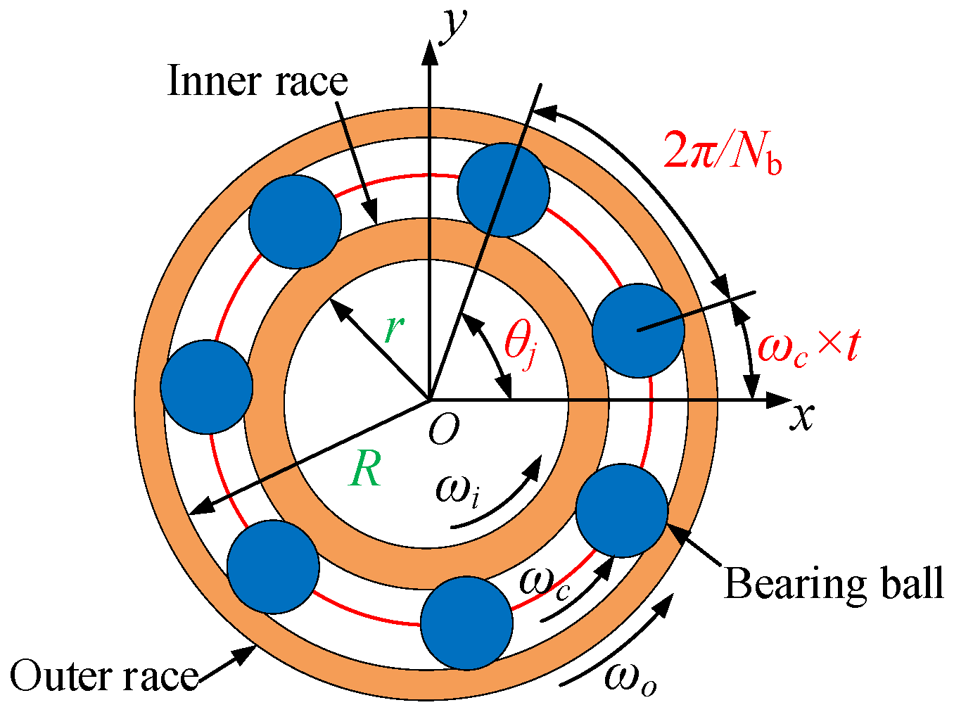
This subsection presents a bearing force model that considers the movement of the bearing outer race and the SC. Each combined support includes a rolling bearing, which is modeled by Hertz contact theory. Figure 2 illustrates the schematic diagram of the bearing, whose components include the inner race, outer race, and rolling balls. An interference fit is adopted for the connection between the inner races and the shaft, while the outer race of the bearing is mounted in the squirrel cage elastic support. Since the movement of the squirrel cage is considered, the outer races of bearings are not fixed.
The tangential velocities of the bearings’ outer (vi) and inner races (vo) are
v i = ω i × r v o = ω o × R
where ωi represents the angular velocity of the inner race, which is equal to the rotational speed of the shaft; ωo represents the angular velocity of the outer race, and its value is 0; r and R denote the radius of the inner and outer races, respectively.
The angular velocity of the bearing cage can be obtained as
ω c = ( v i + v o ) / 2 ( r + R ) / 2 = ω i × r + ω o × R r + R
Furthermore, the angle of j-th rolling element at time t may be computed as follows:
θ j = 2 π ( j 1 ) N + ω c t   , ( j = 1 , 2 , N )
in which N denotes the number of rolling balls.
For the combined support rotor system in practical scenarios, the outer ring of the bearing is mounted on the SC, and the SC is prone to deformation. Consequently, the outer ring of the bearing is not stationary; rather, its displacement is identical to that of the SC. More specifically, when taking into account the coupled motion between the bearing and the SC, the displacement of the squirrel cage is incorporated into the analysis of bearing deformation. The deformation of the n-th combined support and the mathematical expression for the j-th rolling ball is
δ n j = ( x s n x m ) cos θ j + ( y s n y m ) sin θ j r 0
where xsn and ysn represent the vibration displacements of the n-th squirrel cage. xm and ym represent the vibration displacements of the m-th node, and m is equal to 4 or 12. The initial clearance of bearing is represented by r0.
For the n-th combined support, its bearing forces in the x- and y-directions can then be formulated as
F B x n F B y n = k b j = 1 N b ( δ n j ) 3 / 2 H ( δ n j ) cos θ j sin θ j
where kb represents the Hertz contact stiffness. H(·) is a Heaviside function.

2.2. Dynamic Modeling of SC Elastic Support

In this subsection, the dynamic model of the squirrel cage is presented, considering the motion of the squirrel cage and the outer race of bearings, and this better conforms to the actual situation. Figure 1a shows that the bearing outer race is installed in the squirrel cage elastic support instead of a rigid bearing housing, which results in the bearing outer race not being fixed.
The vibration originating from the rotating shaft is transmitted to the outer race of the bearing and the squirrel cage via the inner race in the form of bearing reaction forces (−FB). At this time, the bearing outer race and the squirrel cage as a whole are regarded as a concentrated mass point. Under the excitation of bearing reaction force, the squirrel cage, together with the bearing outer race, will generate vibration displacements xs and ys. Assuming that the squirrel cage is symmetrical in the x and y directions, the mass, stiffness, and damping in the x and y directions are the same. As shown in Figure 1c, the combined support can be simplified as a 2-degree-of-freedom (DOFs) forced vibration system, and the motion equations are as follows:
m s n x ¨ s n + c s n ( x ˙ s n - x ˙ m )   +   k s n ( x s n x m )   = F B x n m s n y ¨ s n + c s n ( y ˙ s n - y ˙ m )   +   k s n ( y s n y m )   = F B y n
where the subscript n represents the index of combined support. msn, csn and ksn are the mass, damping, and stiffness of the squirrel cage. It is important to note that while the mass distribution of the squirrel cage demonstrates negligible influence on the linear vibration response of the rotor system, the current study operates under the assumption that this minimal influence extends to nonlinear vibration responses as well. This constitutes the rationale behind employing a 2-degrees-of-freedom lumped mass model for the squirrel cage, while also representing a recognized limitation of this work.
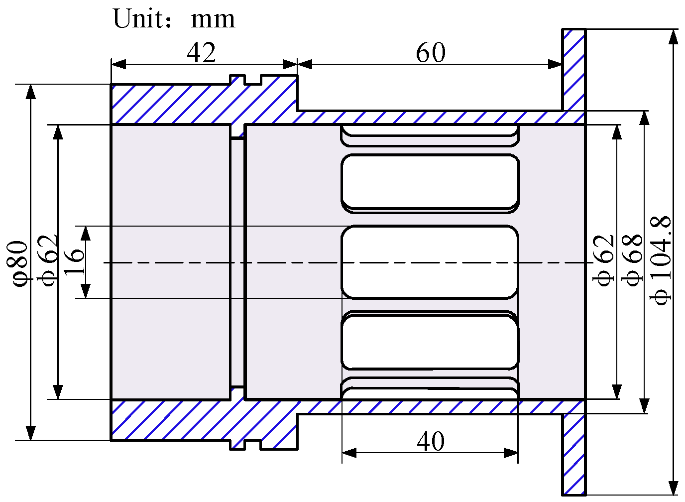
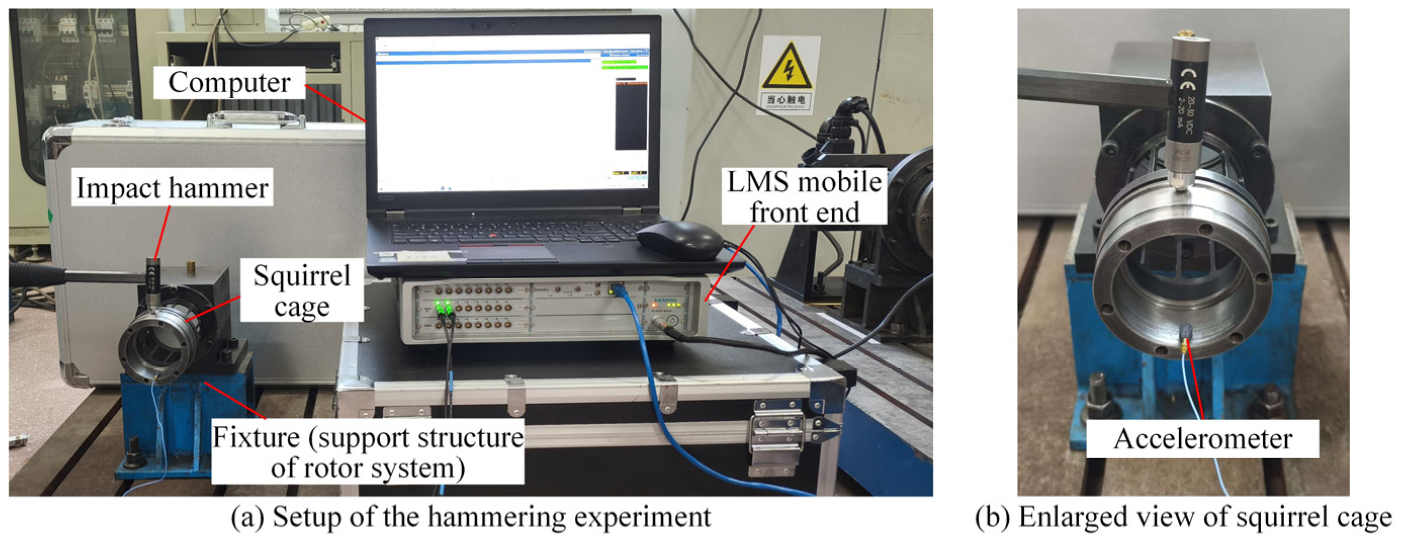
The schematic illustration and dimensional parameters of SC investigated in this paper are presented in Figure 3. The dynamic stiffness of SC is considered, i.e., the stiffness ksn varies with the excitation frequency (rotational speed). The dynamic stiffness of SC is obtained through a hammering experiment, and the experimental setup is shown in Figure 4. One end of the SC is fixed, which is in line with the constraints during its operation. The impact hammer (PCB 086C01) is used to excite the other end of SC, and the excitation force F(ω) is measured by the impact hammer. The accelerometer (PCB 352C22) and LMS SCADAS mobile front end are employed to acquire the acceleration x ¨ ω . The acceleration can be converted to displacement in the frequency domain as follows:
x ¨ ω = ω 2 x ω
The dynamic stiffness ksn can be obtained as follows:
K s n = F ω x ω = ω 2 F ω x ¨ ω
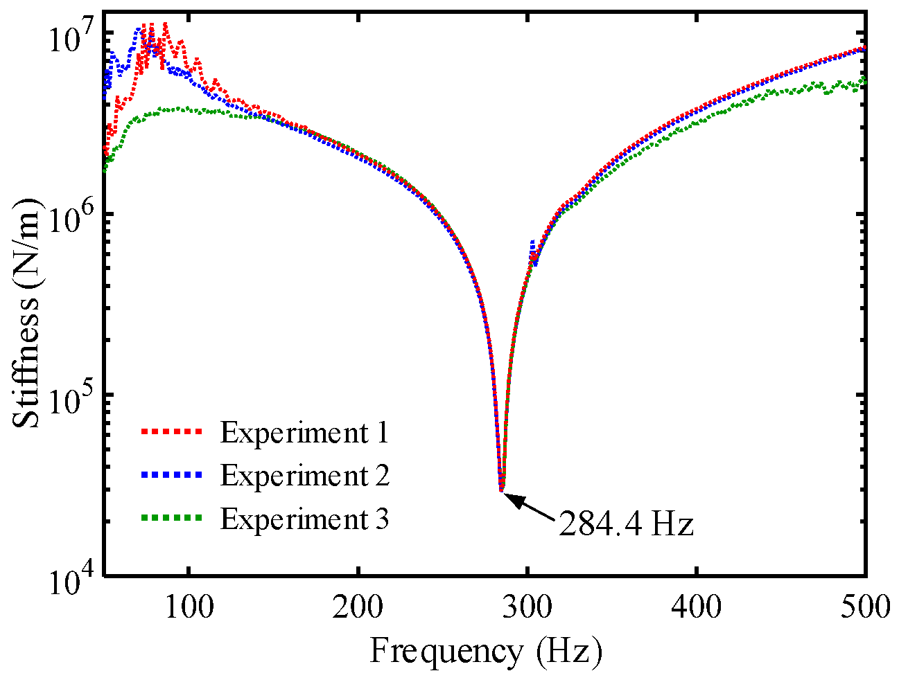
Therefore, the dynamic stiffness of SC can be calculated by the experimental results, as shown in Figure 5. To ensure the validity of the experimental results, the experiment is replicated three times. It can be seen that as the excitation frequency varies, the stiffness exhibits a trend of first decreasing and then increasing. The natural frequency ωns of SC is 284.4 Hz, and the stiffness reaches its minimum value at the natural frequency. Subsequently, the dynamic stiffness is incorporated into Equation (6), and its value varies in accordance with the rotational speed.
The damping ratio of SC is measured through the LMS SCADAS mobile front end of the hammering experiment. The measured damping ratio ξsn is 0.015, and the damping coefficient csn can be obtained as follows [84]:
c s n = 2 m s n ξ s n ω ns
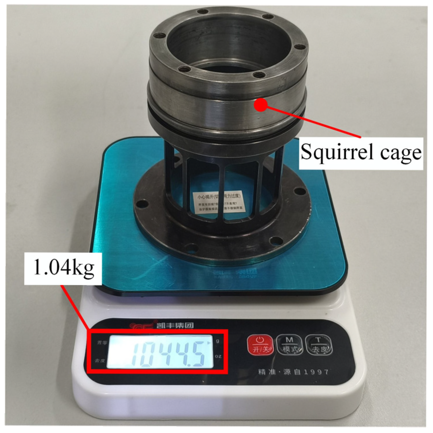
The mass msn of SC is 1.04 kg, which is measured by weighing, as shown in Figure 6. Therefore, the damping coefficient csn of SC can be calculated and is listed in Table 1 along with other parameters. Note that the dynamic stiffness ksn of SC is shown in Figure 4. It is assumed that SC is symmetric in the x- and y- directions. Thus, the mass, stiffness, and damping in the x- and y- directions are identical. The subscript n represents the index of combined support, which is equal to 1 or 2. The SCs of combined support 1 and 2 are identical.

2.3. Governing Equations for the Combined Support-Rotor System

The rotor system is constructed using 8-degrees-of-freedom Timoshenko beam elements, and each node of the finite element contains 2 translational degrees of freedom as well as 2 rotational degrees of freedom. The elastic rotating shaft is divided into 13 Timoshenko beam elements, with a total of 14 nodes. The shear, tension, bending deformations, gyroscopic torques, rotational inertia of the rotor, and the coupling with elastic supports supports through nonlinear forces are considered. For the beam element, its generalized displacement vector is expressed as
q e = x k ,   y k ,   θ x k ,   θ y k ,   x k + 1 ,   y k + 1 ,   θ x k + 1 ,   θ y k + 1 T   ( k = 1 ,   2 ,   ,   13 )
The mass, stiffness, and gyroscopic matrices can be expressed as
M T e = ρ A l 1 + φ s 2 T 1 0 T 1 0 T 4 T 2 symm T 4 0 0 T 2 T 3 0 0 T 5 T 1 0 T 3 T 5 0 0 T 1 0 T 5 T 6 0 0 T 4 T 2 T 5 0 0 T 6 T 4 0 0 T 2 + ρ I l 1 + φ s 2 R 1 0 R 1 0 R 4 R 2 symm R 4 0 0 R 2 R 1 0 0 R 4 R 1 0 R 1 R 4 0 0 R 1 0 R 4 R 3 0 0 R 4 R 2 R 4 0 0 R 3 R 4 0 0 R 2
K B e = E I l 3 1 + φ s B 1 0 B 1 0 B 4 B 2 symm B 4 0 0 B 2 B 1 0 0 B 4 B 1 0 B 1 B 4 0 0 B 1 0 B 4 B 3 0 0 B 4 B 2 B 4 0 0 B 3 B 4 0 0 B 2
G e = ρ I 15 l 1 + φ s 2 0 G 1 0 G 2 0 0 antisymm 0 G 2 G 4 0 0 G 1 G 2 0 0 G 1 0 0 G 2 G 1 0 G 2 0 0 G 3 G 2 0 0 0 G 2 G 3 0 0 G 2 G 4 0
where
T 1 = 13 35 + 7 10 φ s + 1 3 φ s 2 ,   T 2 = 1 105 + 1 60 φ s + 1 120 φ s 2 l 2 T 3 = 9 70 + 3 10 φ s + 1 6 φ s 2 ,   T 4 = 11 210 + 11 120 φ s + 1 24 φ s 2 l T 5 = 13 420 + 3 40 φ s + 1 24 φ s 2 l ,   T 6 = 1 140 + 1 60 φ s + 1 120 φ s 2 l 2
R 1 = 5 6 R 2 = 2 15 + 1 6 φ s + 1 3 φ s 2 l 2 R 3 = 1 30 + 1 6 φ s 1 6 φ s 2 l 2 R 4 = 1 10 1 2 φ s l
φ s = 12 E I G A s l 2   A s = 6 A 1 + μ 7 + 6 μ I = π 64 D 4 d 4
B 1 = 12 B 2 = 4 + φ s l 2 B 3 = 2 φ s l 2 B 4 = 6 l , G 1 = 36 G 2 = 3 l 15 l φ s G 3 = l 2 + 5 l 2 φ s 5 l 2 φ s 2 G 4 = 4 l 2 + 5 l 2 φ s + 10 l 2 φ s 2
In addition, the rigid disk is considered as a 4 DOFs element and is added to the rotor system according to the corresponding node. The mass, stiffness, and unbalance force matrices of the disk can be written as follows:
M d = m d 0 0 0 0 m d 0 0 0 0 J d 0 0 0 0 J d
G d = 0 0 0 0 0 0 0 0 0 0 0 J p 0 0 J p 0
F d = m d e Ω 2 1 0 0 0 cos Ω t + m d e Ω 2 0 1 0 0 sin Ω t
where e represents the eccentricity of the disk.
The bearing force vector FB can be written as follows:
F B =   F B x 1   F B y 1     F B x 2   F B y 2 T
For the rotor system without the combined support, its motion equation can be obtained by assembling the matrices of the disk and the shaft, which is expressed as follows:
M r q ¨ r + C r Ω G r q ˙ r + K r q r = F d + F B
in which Mr, Cr, Kr, and Gr denote the mass matrix, damping matrix, stiffness matrix, and gyroscopic matrix for the rotor system without the combined support, respectively. Note that the structural damping of the system is characterized by Rayleigh damping. The damping ratio is revised according to the experimental results (Section 4), and its value is 0.04.
The motion equation for combined supports is subsequently added to the matrices of the rotor system. Therefore, the dynamics equation of the combined support-rotor can be expressed as:
M r 0 0 0 M s 1 0 0 0 M s 2 q ¨   + C r Ω G r 0 0 0 C s 1 0 0 0 C s 2 q ˙ + K r 0 0 0 K s 1 0 0 0 K s 2 q = F d + F B

3. Discussions of Numerical Simulation Results

The key focus of this section is to investigate the dynamic behaviors of the support-rotor assembly system, with particular emphasis on the effect of the combined support on the rotor-bearing system. The physical parameters of the rotor and bearing are listed in Table 2 and Table 3, respectively. Section 3.1 and Section 3.2 comparatively analyze the effect of the combined support on the nonlinear vibration of the rotor system. In Section 3.3, this study examines how bearing clearance affects the response of rotor systems for both support forms, where the nonlinear vibration behaviors are solved by the Newmark method. New vibration behaviors of the combined support-rotor system are discovered through amplitude–frequency responses, frequency spectrums, time waveform, Poincaré map, and variation in contact load. It is important to note that damping is essential for ensuring the validity of the system response. In this study, Rayleigh damping is adopted to represent the structural damping of the system. The damping ratio is subsequently calibrated against experimental results, yielding a final value of 0.04. This calibrated value is applied in simulations to obtain the dynamic response.
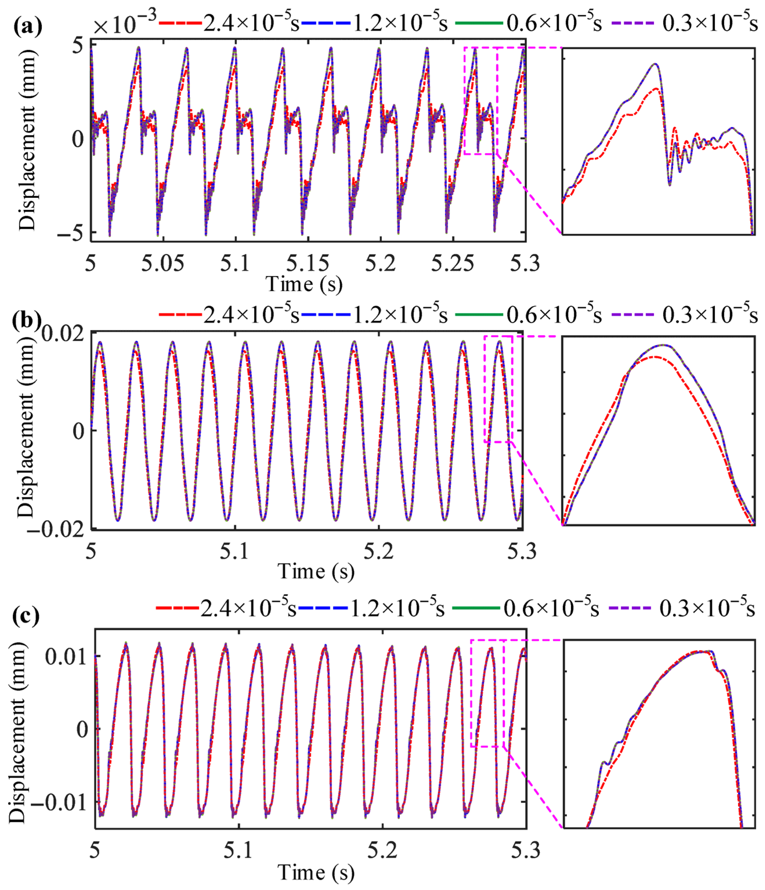
In order to validate the effectiveness of the solution obtained by the Newmark method, a convergence analysis is conducted through the evaluation of calculation results corresponding to different time-step sizes. For the comparative analysis, four time-step sizes are selected, specifically 2.5 × 10⁻⁵ s, 1.2 × 10⁻⁵ s, 0.6 × 10⁻⁵ s, and 0.3 × 10⁻⁵ s. The comparison of time-domain responses with different time steps is presented in Figure 7. Three rotational speeds of 0.63ωn1 (before resonance), ωn1 (resonance), and 1.09ωn1 (after resonance) are selected for comparison. As the time-step size diminishes, the vibration response ceases to vary starting from 1.2 × 10⁻⁵ s, which demonstrates the convergence of the calculation results. Therefore, to further guarantee the solution accuracy, a time step of 0.6 × 10⁻⁵ s is chosen for the computations in this study.

3.1. Dynamic Analysis of Rotor-Bearing System Under Unbalance Excitation

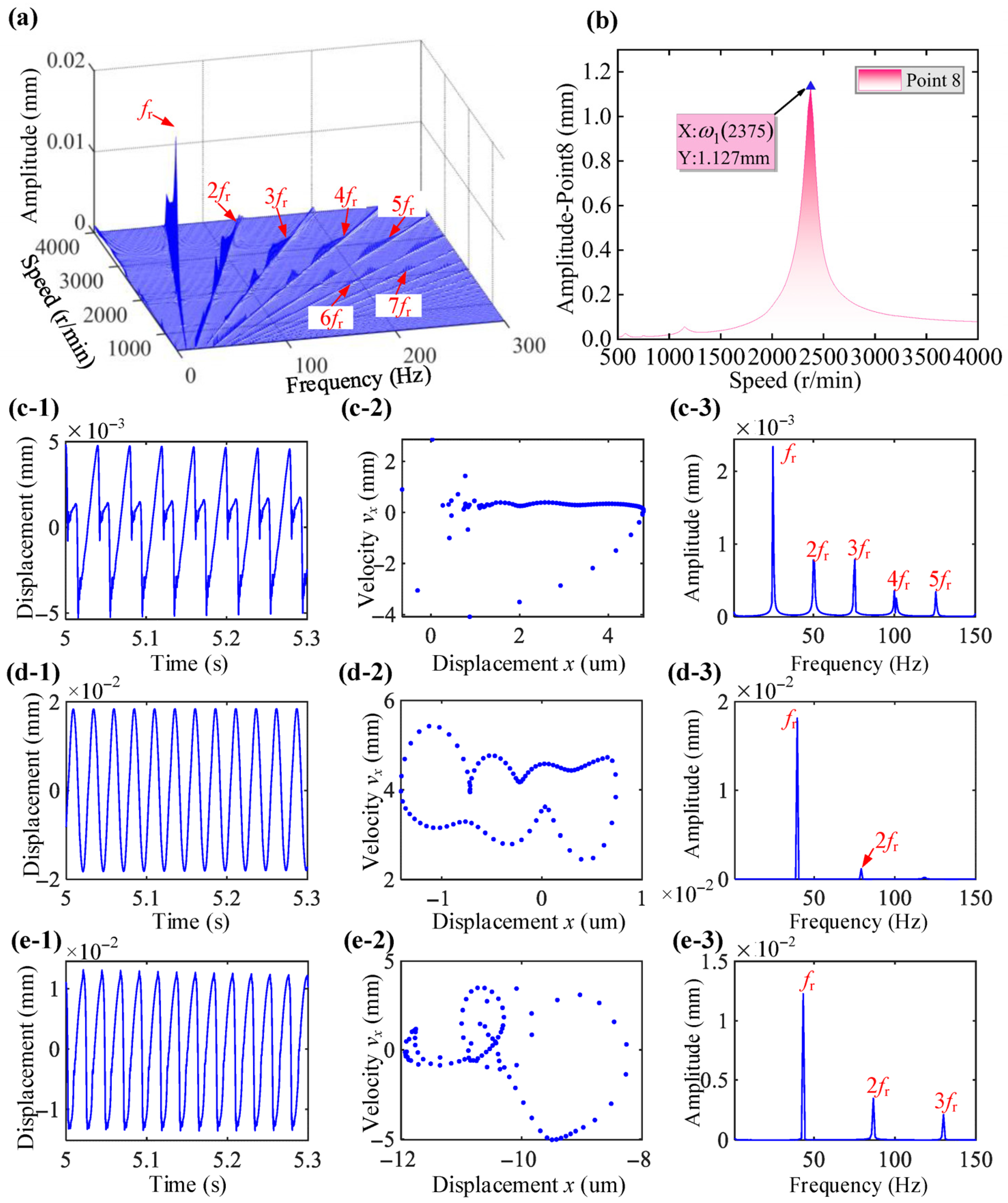
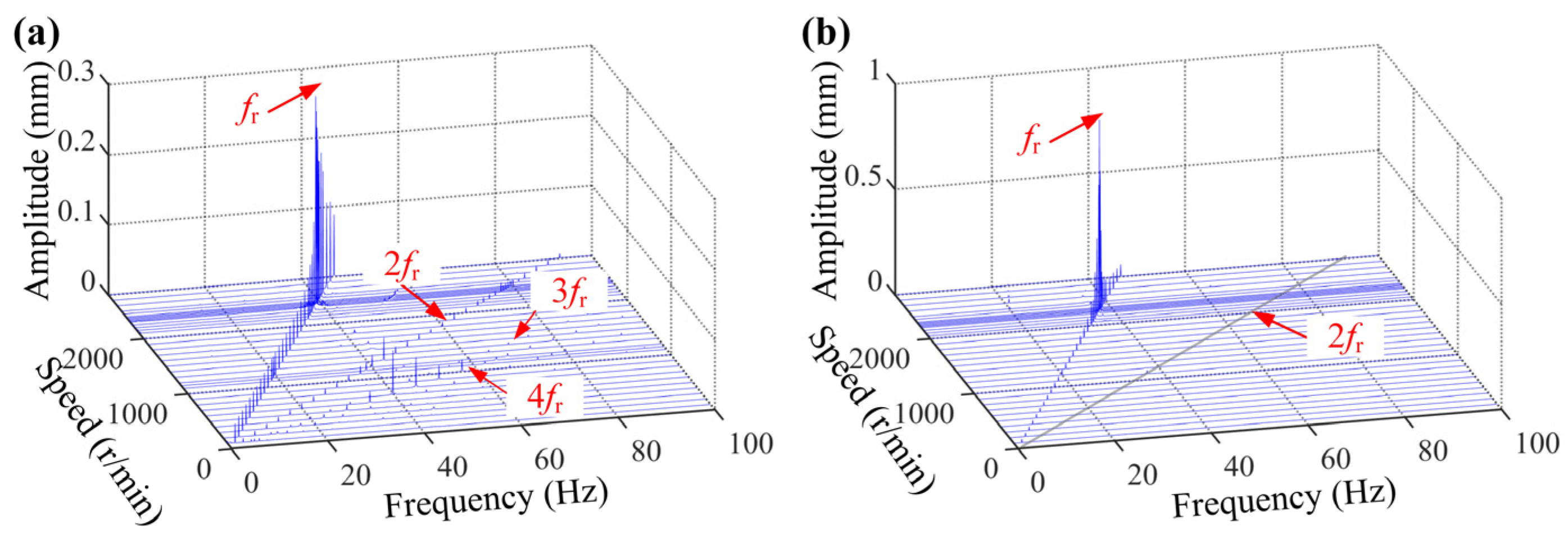
Spectrum cascades under different speeds are seen in Figure 8a. The analysis reveals that obvious nonlinear vibration behaviors are present, with the main frequency components being fr, 2fr, 3fr, 4fr, 5fr, etc., and the amplitudes gradually decreasing. Figure 8b illustrates the amplitude–frequency responses at node 4 (support) and 7 (disk), where the critical speed ωn1 of rotor systems supported only by bearings is 2375 r/min. The vibration amplitude at node 4 is much smaller than that at node 7. This is because the bearing has a strong constraint, and the deformation mainly occurs on the shaft. Figure 8c–e demonstrates the vibration response at speeds of 0.63ωn1, ωn1, and 1.09ωn1, respectively. The obvious 2fr, 3fr, etc., before and after the critical speed emerge. Moreover, the shape of the Poincaré map is irregular, and the rotor’s motion behavior is close to a chaotic regime.

3.2. Dynamic Analysis of RBS Considering Dynamic Stiffness

In this section, an analysis is conducted on the dynamic characteristics of RBS, where the effect of combined support is considered. Furthermore, the vibration responses under the conditions of combined support and bearing support only are compared.
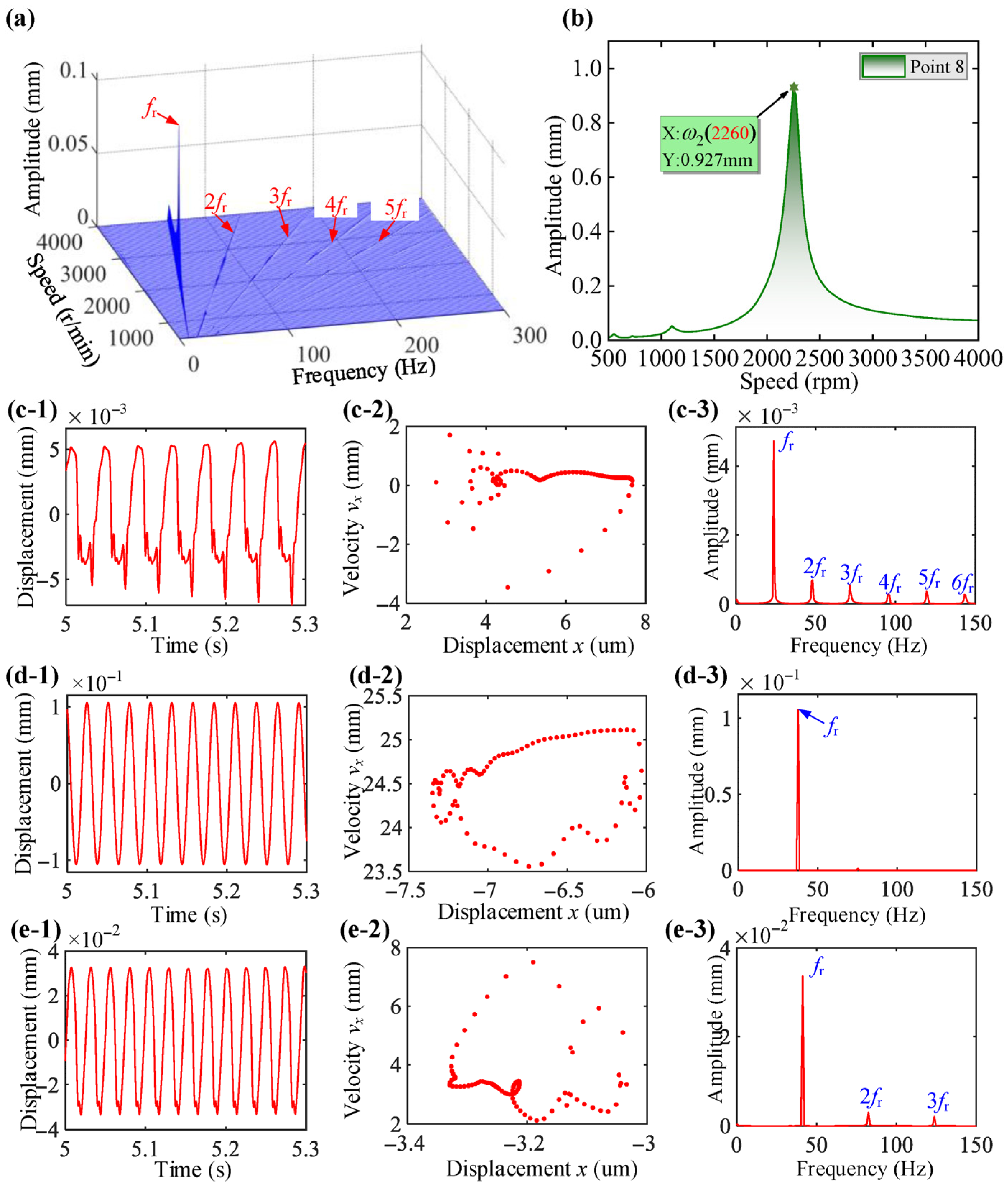
Figure 9a illustrates the spectrum cascades for the rotor system supported by combined supports across a range of rotational speeds. Compared with Figure 8a, the vibration amplitudes of 2fr, 3fr, 4fr, 5fr, etc., are significantly reduced, which indicates that the nonlinearity of the rotor system is weakened by the combined support. It can be seen from Figure 9b that the critical speed ωn2 of the combined-supported rotor system is 2260 r/min. The critical speed ωn2 is reduced compared to the case with only bearing support (ωn1) because the combined support is flexible. This also indicates that the combined support contributes to adjusting the critical speed of the rotor system.
Figure 9c–e show time-domain response curves of the system at different speeds. The shape of the Poincaré map is approximately circular, and it can be concluded that the rotor system is in a quasi-periodic motion state under the current conditions. Compared with Figure 9c–e, the rotor operates with greater stability. In addition, the amplitudes of ultraharmonics have also decreased.
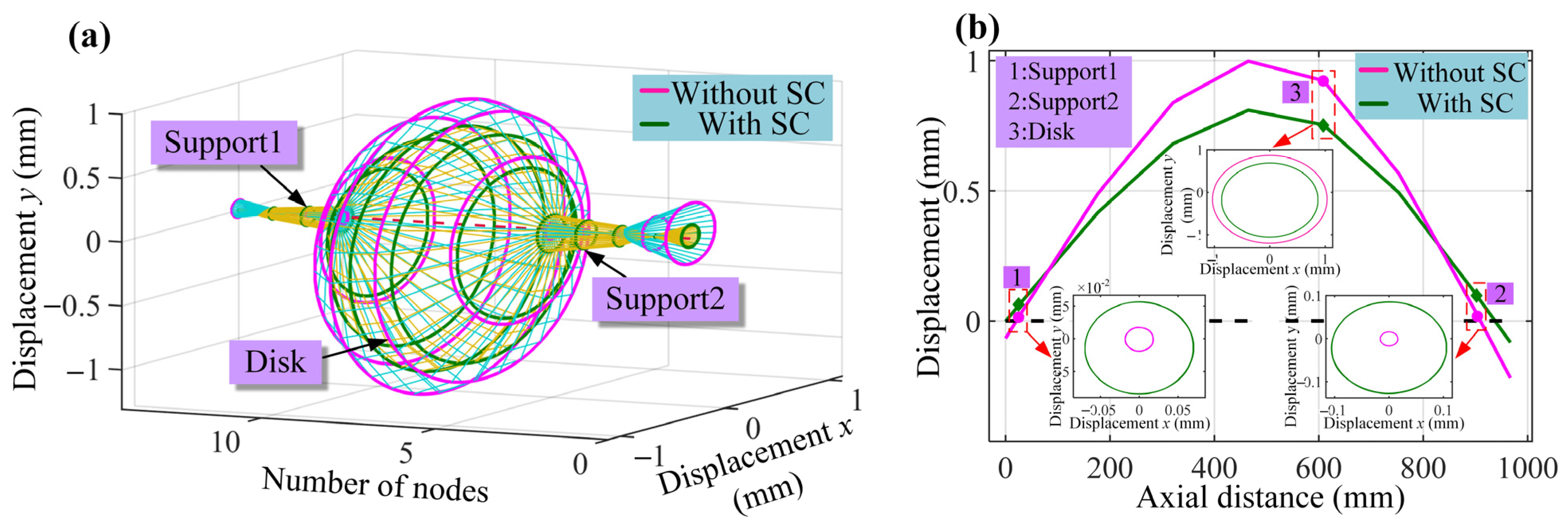
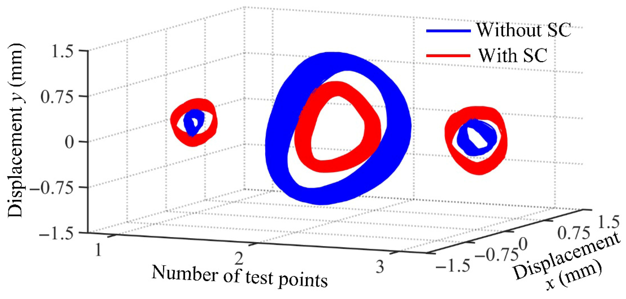
For a thorough investigation into the influence of combined supports on the RBS, as illustrated in Figure 10, a comparison of the rotor orbit and vibration amplitude under two support forms is presented. It can be seen that combined support increases vibration near the rotor support and significantly reduces the vibration of the shaft. Because the squirrel cage absorbs the energy of the RBS vibration through the elastic deformation of the structure, the vibration of the shaft is greatly weakened, which is conducive to the stable operation of the RBS.
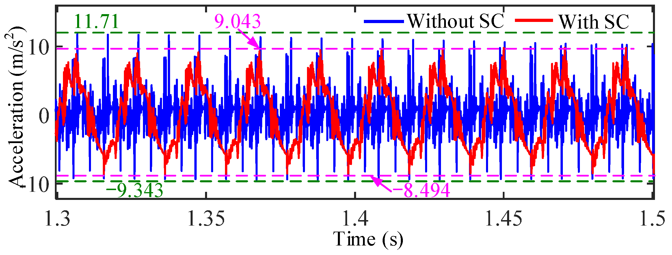
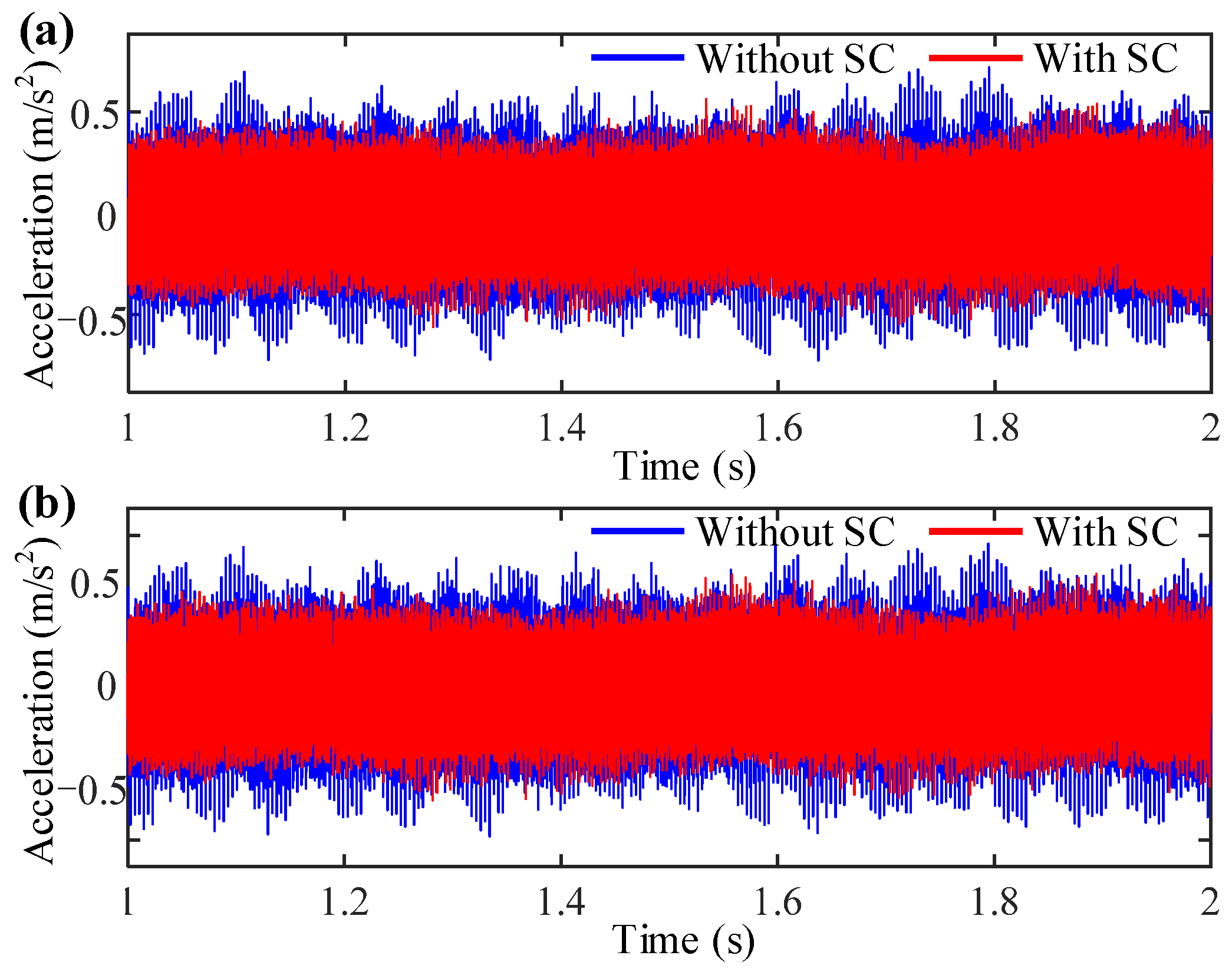
Furthermore, the effect of the combined support on the reaction force is studied by comparing the accelerations under different supports, as shown in Figure 11. When the squirrel cage (SC) is considered, the amplitude of the vibration acceleration has decreased significantly. Thus, the SC lessens the rotor’s reaction force while boosting the stability of both the rotor and its supporting structures.

3.3. Effect of Bearing Clearance

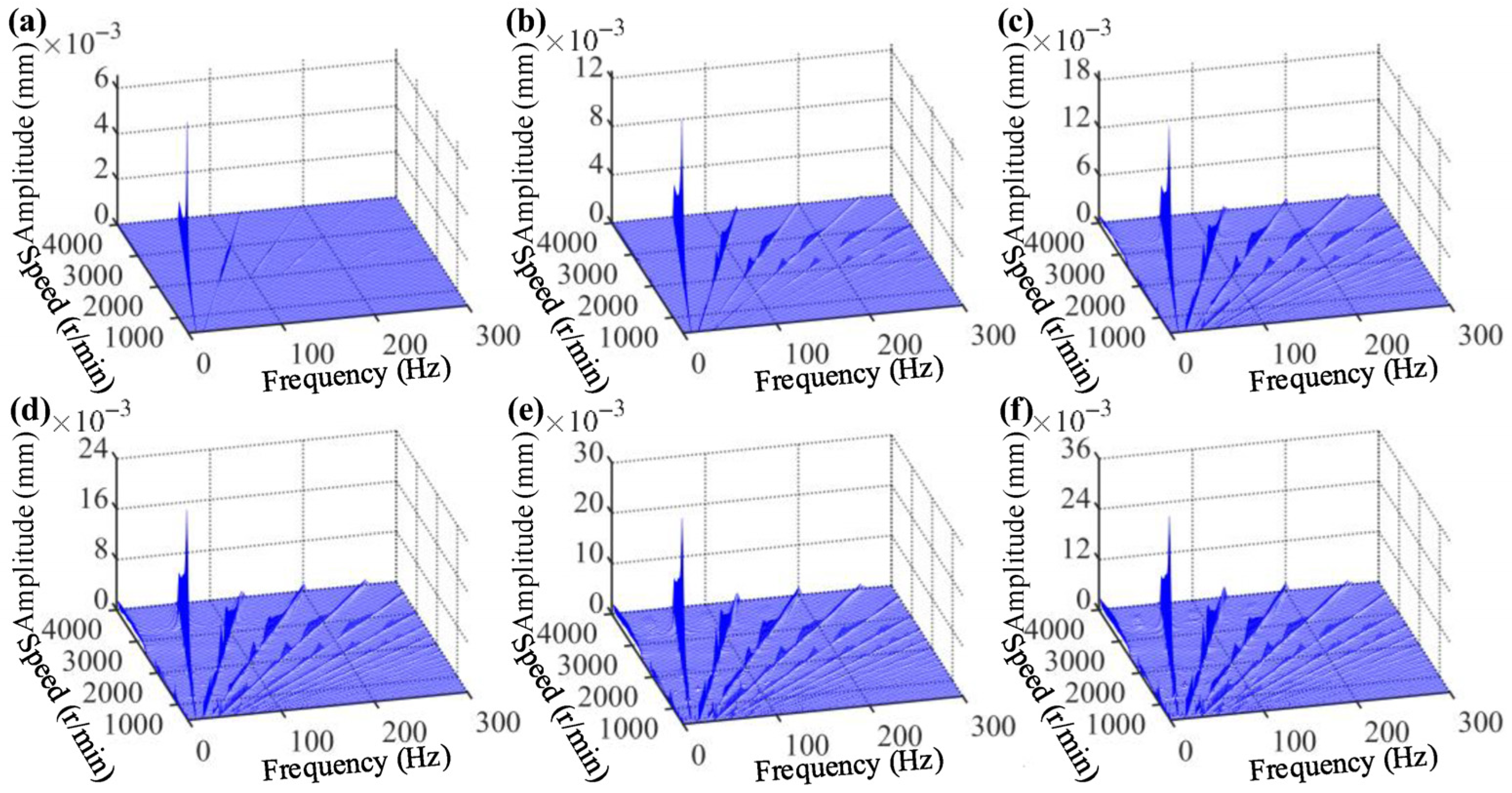
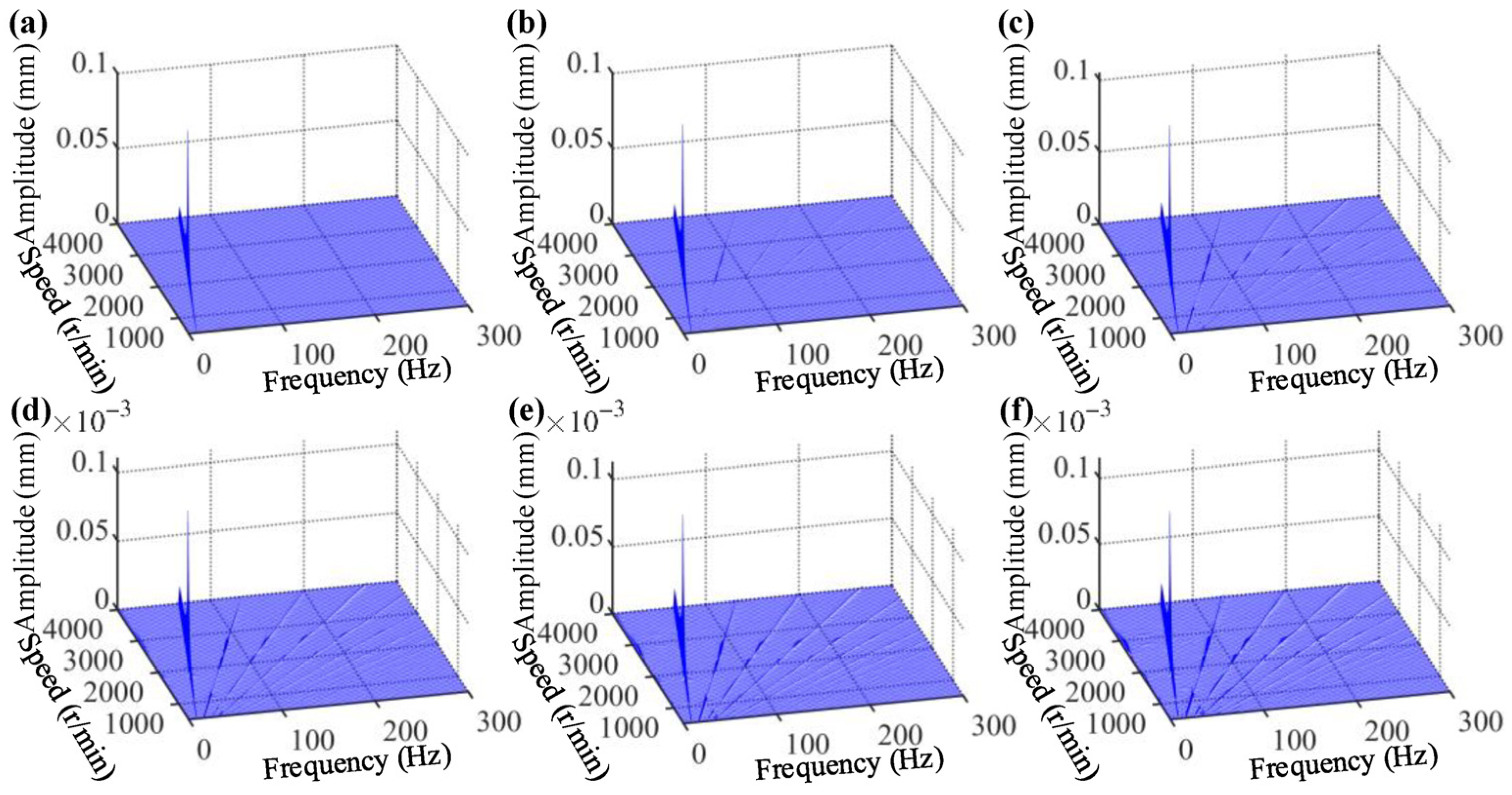
This section focuses on the effect of different bearing initial clearances on the vibration characteristics of the RBS under combined support. Figure 12 and Figure 13, respectively, show the waterfall plots under the bearing support and the combined support. As the initial bearing clearance increases, frequency components become increasingly complex and the amplitudes rise higher and higher. Figure 12 and Figure 13 are analyzed comparatively to highlight their differences in dynamic response, and it is obvious that the combined support significantly reduces the frequency components in each clearance situation.
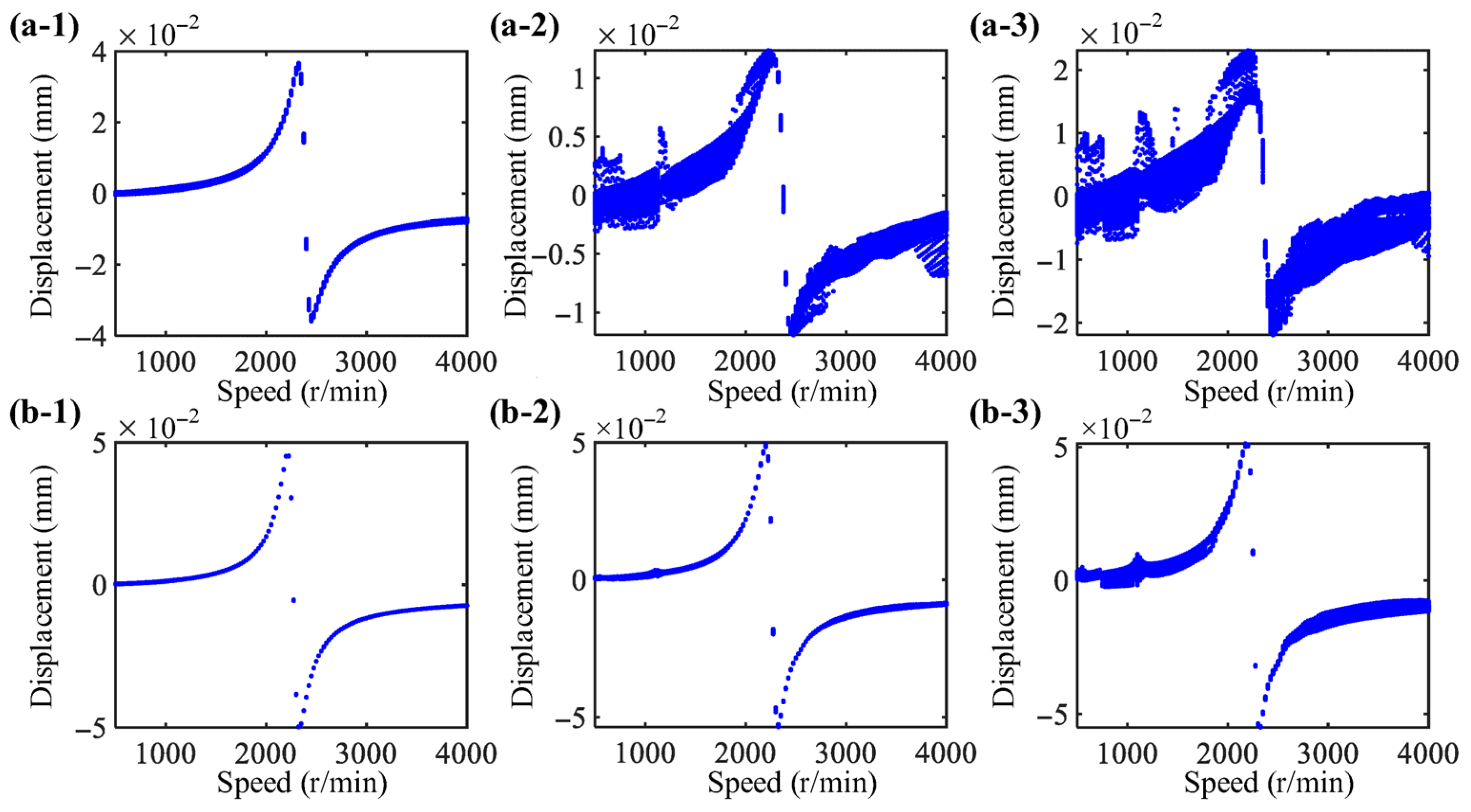
The bifurcation diagrams under the bearing support and combined support are shown in Figure 14. It can be seen that the combined support largely weakens the nonlinear vibration. The rotor supported only by bearing exhibits chaotic motion state at many rotational speeds, while rotor systems supported by combined supports show 1-period or quasi-periodic motion at many rotational speeds. This indicates that the operational stability of the rotor with combined supports has been improved.

4. Experimental Study

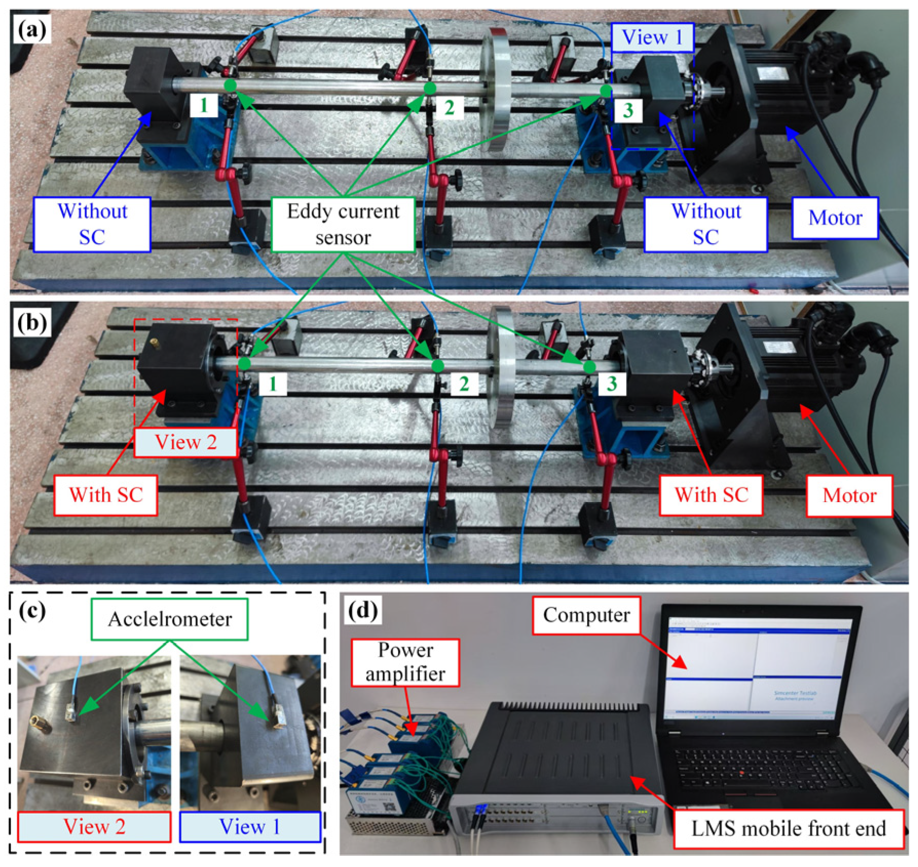
To verify some typical dynamic behaviors of the RBS with combined supports, the test rigs with bearing supports (see Figure 15a) and with combined supports (see Figure 15b) are set up for validation and comparison. The shafts and disks of the two rotor test rigs are the same, with only the supports being different. For the combined support rotor test rig, the bearings are installed in SC, and then SC is fixed to the support structure. Eddy current sensors are employed to measure the vibration displacements at three positions of the rotating shaft. The sensitivity of eddy current sensors is 2000 mV/mm. The accelerometers (356A01, PCB Piezotronics, Inc., Depew, NY, USA) are utilized to measure the vibration acceleration by being attached to the support structure, with a sensitivity of 5.32 mV/g, as shown in Figure 15c. The vibration data acquired by the sensors are collected using an LMS mobile front end (SCM2E05, SIEMENS AG, Berlin, Germany) at a sampling frequency of 2048 Hz, as shown in Figure 15d.

4.1. Model Verification

In this section, a comparison between the simulation and experimental results is conducted to verify the effectiveness of the model. Firstly, the damping of the rotor system is identified by using the particle swarm optimization algorithm, and the optimization objective is the peak of the rotor system resonance. The objective function for the damping coefficients of the rotor system is as follows:
A ξ = x e x s ξ x e
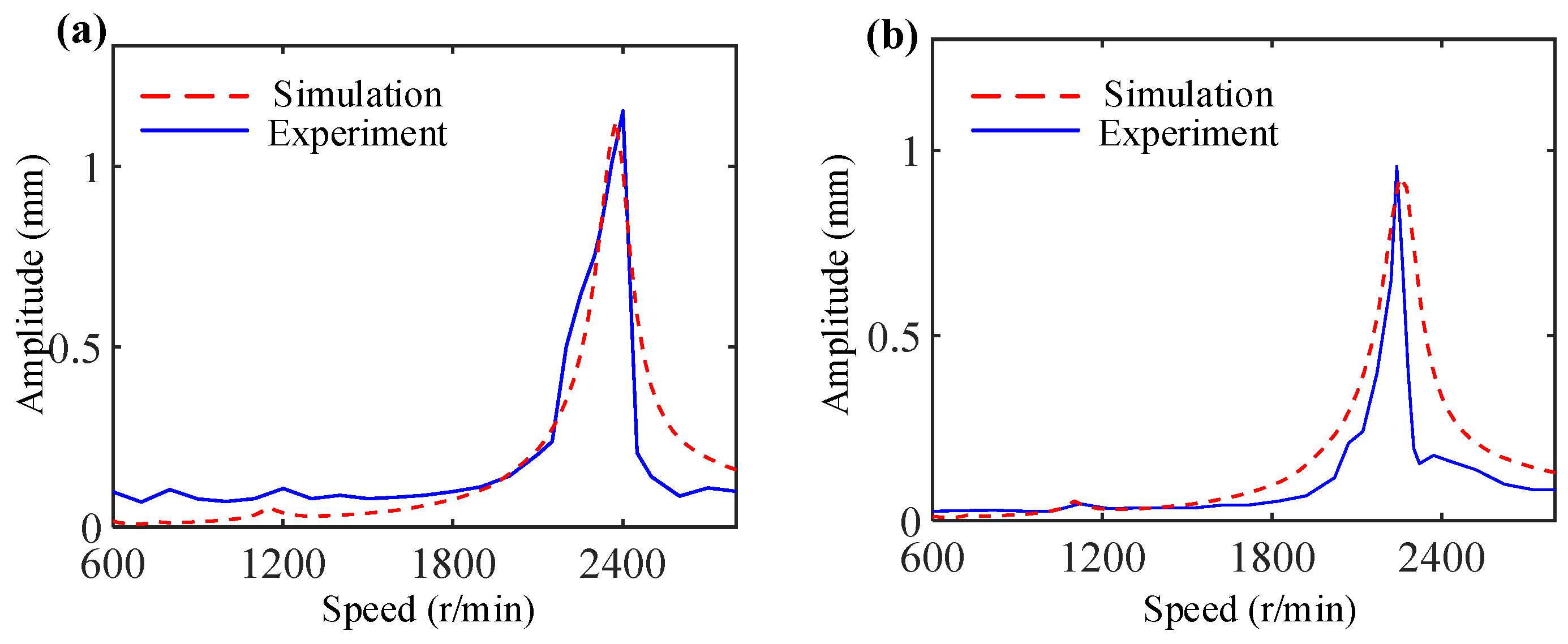
where xe and xs are the resonance amplitudes of the experimental and simulation results. ξ is the damping ratio that needs to be identified. After identification, the damping ratio is 0.04. The identified parameter is incorporated into the model developed in Section 2, and a comparison is made between the amplitude–frequency responses of the optimized simulation and experiment (sensor 2), as shown in Figure 16. The simulation results after optimization exhibit a high degree of consistency with the experimental results, thereby validating the effectiveness of the simulation model.

4.2. Experimental Results

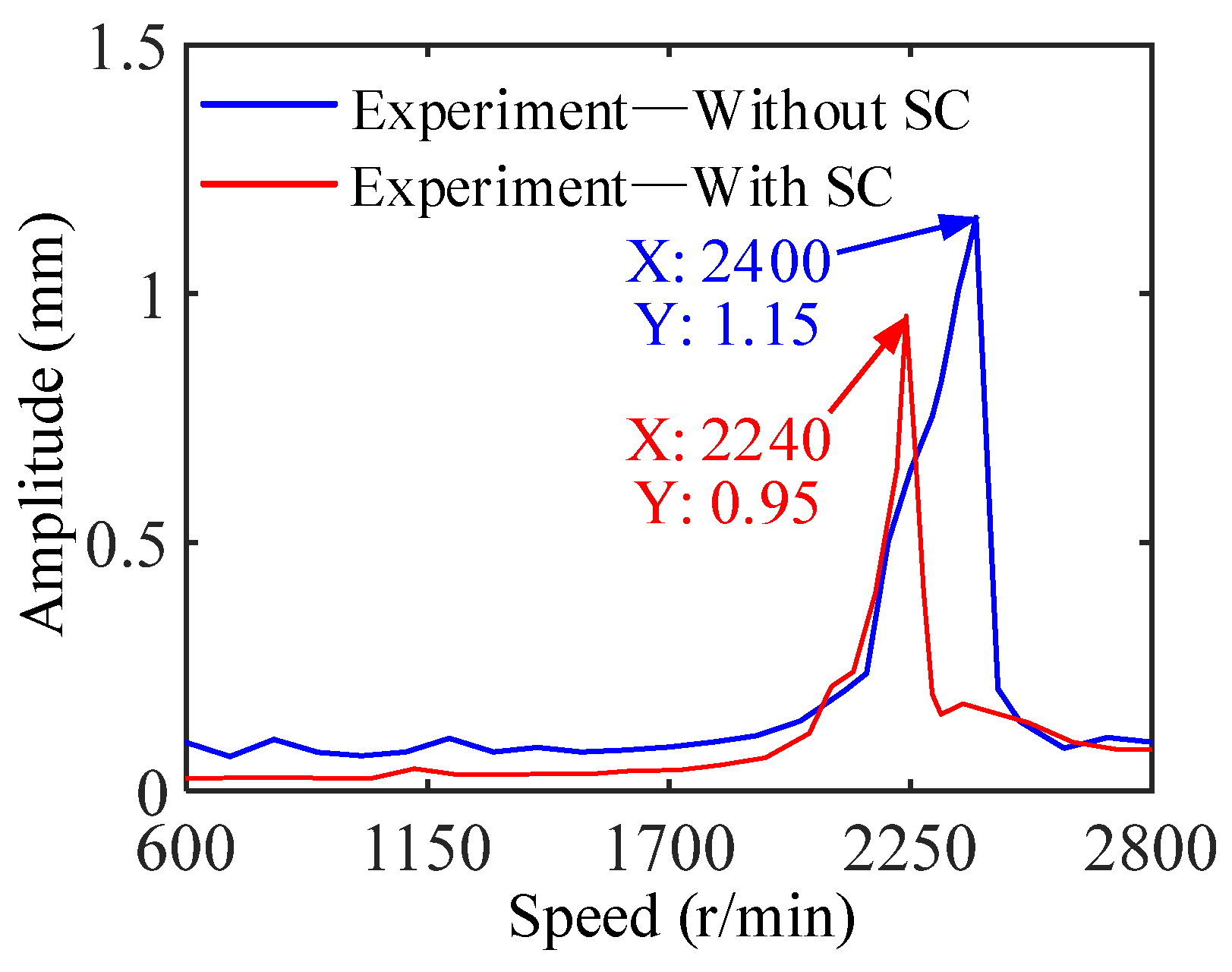
Figure 17 present the measured amplitude–frequency response of the bearing support and the combined support, respectively. The critical speed of bearing supports is 2400 r/min, and that of combined supports is 2240 r/min. Furthermore, the introduction of SC indeed reduces the vibration amplitude at the middle of the rotor, thereby effectively validating our simulation model.
Figure 18 shows the measured spectrum cascades under different speeds with different supports. For the rotor test rig with bearing supports, the frequency components include fr, 2fr, 3fr, 4fr, etc. As for the case of combined supports, only fr and 2fr are obvious. The result of the combined support weakening nonlinearity is verified through experiments.
The measured three-dimensional rotor orbits are illustrated in Figure 19. By comparison, it is found that when the squirrel cage elastic support is introduced, the displacement at both ends of the rotating shaft increases while that in the middle decreases, which this consistent with simulation results in Section 3.2. This is because the squirrel cage absorbs the vibration energy of the rotor through the elastic deformation of the structure, thereby reducing the vibration response in the middle of the rotating shaft.
The measured vibration accelerations with different supports are shown in Figure 20. Analysis shows that combined support reduces the vibration acceleration at the support location, consistent with simulation results, indicating that the squirrel cage elastic support can reduce the reaction force of the rotor.

5. Conclusions

In this work, we develop a dynamic model of the rotor-bearing system with SC. The effect of SC on the RBS is analyzed numerically and experimentally. New vibration behaviors and phenomena are discovered, which reveal the effect of SC on nonlinear rotor systems. The main conclusions are summarized as follows:
  • The nonlinear vibration behavior of the RBS is weakened by the SC elastic support, which is manifested as a reduction in frequency components and a stabilization of the bifurcation diagram. In addition, the SC elastic support can adjust the critical speed of the rotor.
  • The operational deflection shape of the RBS is changed by the squirrel cage elastic support, and vibration energy of the rotor is transformed into deformation of the SC, thereby reducing vibration displacement in the middle of the rotor.
  • For different bearing initial clearance conditions, the squirrel cage elastic support still has a strong weakening effect on the nonlinear vibration of RBS, and nonlinear vibration behavior changes are not significant under different initial bearing clearance conditions.

Author Contributions

Conceptualization, L.L.; methodology, L.L.; software, L.L., T.M., and F.X.; validation, L.L., T.M., and F.X.; formal analysis, F.L.; investigation, L.L. and T.M.; data curation, F.L. and F.X.; writing—original draft preparation, L.L.; writing—review and editing, F.L.; visualization, T.M. and F.X.; funding acquisition, L.L. All authors have read and agreed to the published version of the manuscript.

Funding

This research was funded by the National Natural Science Foundation of China, grant number 5240509; the Guangdong Basic and Applied Basic Research Foundation, grant number 2023A1515110557; the Natural Science Foundation of Liaoning Province, grant number 2023-BSBA-102; the Fundamental Research Funds for the Central Universities of China, grant number N2403022; the Open Project of Guangxi Key Laboratory of Automobile Components and Vehicle Technology in 2024, grant number 2024GKLACVTKF07; the Basic Research Projects of Liaoning Provincial Department of Education, grant number JYTQN2023162; and the Open Fund of National Key Laboratory of Particle Transport and Separation Technology, grant number WZKF-2024–6.

Data Availability Statement

The original contributions presented in this study are included in the article. Further inquiries can be directed to the corresponding author.

Conflicts of Interest

The authors declare no conflicts of interest.

References

  1. Fu, C.; Zheng, Z.; Zhu, W.; Lu, K.; Yang, Y. Nonlinear vibrations of a rotor with support nonlinearities considering bounded uncertainties. Nonlinear Dyn. 2022, 110, 2363–2379. [Google Scholar] [CrossRef]
  2. Hong, J.; Dai, Q.; Yang, Z.; Tian, J.; Sun, B.; Wang, Y.; Song, Z.; Ma, Y. Combination resonance of dual rotor systems with pedestal looseness using a modified model. Int. J. Non-Linear Mech. 2025, 175, 105101. [Google Scholar] [CrossRef]
  3. Xiao, S.; Yu, P.; Jiang, Z.; Wang, C.; Chen, J. Nonlinear Modeling and Vibration Response Analysis of a Dual-Rotor System with an Inter-Shaft Graphite Seal. Mathematics 2024, 12, 454. [Google Scholar] [CrossRef]
  4. Wang, P.; Yang, Y.; Ma, H.; Xu, H.; Li, X.; Luo, Z.; Wen, B. Vibration characteristics of rotor-bearing system with angular misalignment and cage fracture: Simulation and experiment. Mech. Syst. Signal Process. 2023, 182, 109545. [Google Scholar] [CrossRef]
  5. Li, L.; Luo, Z.; Wu, F.; He, F.; Sun, K. Frequency spectrum analysis of the rotor system with bolted joint: Numerical and experimental verification. Appl. Math. Model. 2023, 118, 745–761. [Google Scholar] [CrossRef]
  6. Li, L.; Luo, Z.; He, F.; Qin, Z.; Li, Y.; Yan, X. Similitude for the Dynamic Characteristics of Dual-Rotor System with Bolted Joints. Mathematics 2022, 10, 3. [Google Scholar] [CrossRef]
  7. Lu, Z.; Liu, L.; Wang, X.; Ma, Y.; Chen, H. Dynamic modeling and bifurcation analysis of blade-disk rotor system supported by rolling bearing. Appl. Math. Model. 2022, 106, 524–548. [Google Scholar] [CrossRef]
  8. Xi, S.; Cao, H.; Chen, X. Dynamic modeling of spindle bearing system and vibration response investigation. Mech. Syst. Signal Process. 2019, 114, 486–511. [Google Scholar] [CrossRef]
  9. Cheng, H.; Zhang, Y.; Lu, W.; Yang, Z. Mechanical characteristics and Nonlinear Dynamic response analysis of rotor-bearing-coupling system. Appl. Math. Model. 2021, 93, 708–727. [Google Scholar] [CrossRef]
  10. Li, Y.; Wen, C.; Luo, Z.; Jin, L. Bifurcation studies of a bolted-joint rotor system subjected to fixed-point rubbing fault. Nonlinear Dyn. 2022, 110, 3045–3073. [Google Scholar] [CrossRef]
  11. Li, Y.; Yang, B.; Wen, C. Stability analysis of the bending-torsional vibration of a bolted joint rotor-bearing-support system. Nonlinear Dyn. 2025, 113, 28757–28786. [Google Scholar] [CrossRef]
  12. Jin, Y.; Liu, Z.; Yang, Y.; Li, F.; Chen, Y. Nonlinear vibrations of a dual-rotor-bearing-coupling misalignment system with blade-casing rubbing. J. Sound Vib. 2021, 497, 115948. [Google Scholar] [CrossRef]
  13. Zhang, W.; Ding, Q. Elastic ring deformation and pedestal contact status analysis of elastic ring squeeze film damper. J. Sound Vib. 2015, 346, 314–327. [Google Scholar] [CrossRef]
  14. Zhang, D.; Wu, D.; Han, Q.; Wang, H. Nonlinear Dynamic force transmissibility of a flywheel rotor supported by angular contact ball bearings. Nonlinear Dyn. 2021, 103, 2273–2286. [Google Scholar] [CrossRef]
  15. Saeed, N. On the steady-state forward and backward whirling motion of asymmetric nonlinear rotor system. Eur. J. Mech.-A/Solids 2020, 80, 103878. [Google Scholar] [CrossRef]
  16. Wang, T.; Ding, Q. Nonlinear normal modes and dynamic balancing for a nonlinear rotor system. Nonlinear Dyn. 2024, 112, 10823–10844. [Google Scholar] [CrossRef]
  17. Wang, P.; Xu, H.; Yang, Y.; Ma, H.; He, D.; Zhao, X. Dynamic characteristics of ball bearing-coupling-rotor system with angular misalignment fault. Nonlinear Dyn. 2022, 108, 3391–3415. [Google Scholar] [CrossRef]
  18. Wang, Z.; Sun, R.; Liu, Y.; Yao, Y.; Tian, J. Analysis of Nonlinear Vibration Characteristics and Whirl Behavior of Dual-Rotor Systems with Inter-Shaft Rub Impact. Mathematics 2024, 12, 1436. [Google Scholar] [CrossRef]
  19. Wang, N.; Jiang, D. Vibration response characteristics of a dual-rotor with unbalance-misalignment coupling faults: Theoretical analysis and experimental study. Mech. Mach. Theory 2018, 125, 207–219. [Google Scholar] [CrossRef]
  20. Chen, R.; Lv, J.; Tian, J.; Ai, Y.; Zhang, F.; Yao, Y. Modeling and Nonlinear Dynamic Characteristics Analysis of Fault Bearing Time-Varying Stiffness-Flexible Rotor Coupling System. Mathematics 2024, 12, 3591. [Google Scholar] [CrossRef]
  21. Kim, J.; Hong, J.G.; Chung, J. Nonlinear Dynamic modeling and response analysis of a rotor–blade system with whirling motion. Nonlinear Dyn. 2019, 98, 953–970. [Google Scholar] [CrossRef]
  22. Kang, Y.; Cao, S.; Hou, Y.; Chen, N.; Li, B. Dynamics research on the rubbing process and rubbing forms of rotor-blade-casing systems. Int. J. Non-Linear Mech. 2022, 147, 104242. [Google Scholar] [CrossRef]
  23. Chen, G.; Qu, M. Modeling and analysis of fit clearance between rolling bearing outer ring and housing. J. Sound Vib. 2019, 438, 419–440. [Google Scholar] [CrossRef]
  24. Li, L.; Luo, Z.; He, F.; Sun, K.; Yan, X. An improved partial similitude method for dynamic characteristic of rotor systems based on Levenberg–Marquardt method. Mech. Syst. Signal Process. 2022, 165, 108405. [Google Scholar] [CrossRef]
  25. Li, L.; Luo, Z.; Liu, K.; Zhou, J. Dynamic stiffness characteristics of aero-engine elastic support structure and its effects on rotor systems: Mechanism and numerical and experimental studies. Appl. Math. Mech. 2023, 44, 221–236. [Google Scholar] [CrossRef]
  26. Li, L.; Luo, Z.; Wu, F.; He, F.; Sun, K. Experimental and numerical studies on partial similitude of rotor system considering the vibration consistency. Mech. Mach. Theory 2023, 183, 105270. [Google Scholar] [CrossRef]
  27. Zhu, T.; Zang, C.; Wei, X.; Chen, H.; Wang, H. Nonlinear model updating of the rotor-bearing system by multi-harmonic balance method and analytical sensitivity derivation. Int. J. Non-Linear Mech. 2024, 161, 104688. [Google Scholar] [CrossRef]
  28. Wang, Z.; Liang, X.; Wang, Z.; Zhang, K.; Zhou, P. Effect of cage pocket wear on the Nonlinear Dynamics of a full-ceramic bearing-rotor system under starved conditions. Int. J. Non-Linear Mech. 2024, 170, 104973. [Google Scholar] [CrossRef]
  29. Hou, L.; Chen, Y.; Cao, Q.; Lu, Z. Nonlinear vibration analysis of a cracked rotor-ball bearing system during flight maneuvers. Mech. Mach. Theory 2016, 105, 515–528. [Google Scholar] [CrossRef]
  30. Ma, S.; Yin, Y.; Chao, B.; Yan, K.; Fang, B.; Hong, J. A real-time coupling model of bearing-rotor system based on semi-flexible body element. Int. J. Mech. Sci. 2023, 245, 108098. [Google Scholar] [CrossRef]
  31. Wang, P.; Yang, Y.; Xu, H.; Ma, H.; Han, Q.; Luo, Z.; Wen, B. Effect of static and dynamic misalignment of rolling bearing on nonlinear vibration characteristics of rotor system. J. Cent. South Univ. 2023, 30, 871–903. [Google Scholar] [CrossRef]
  32. Li, Y.; Yang, B.; Wen, C.; Luo, Z.; Li, B. Dynamic modeling and analysis for lateral-torsional coupling vibration of a bolted joint rotor system during speed-up process. Commun. Nonlinear Sci. Numer. Simul. 2025, 150, 109012. [Google Scholar] [CrossRef]
  33. Li, L.; Luo, Z.; He, F.; Ding, Z.; Sun, K. A partial similitude method for vibration responses of rotor systems: Numerical and experimental verification. Int. J. Mech. Sci. 2021, 208, 106696. [Google Scholar] [CrossRef]
  34. Luo, Z.; Liang, B.; Sun, K.; Li, L.; Hao, H.; Wu, X. Dynamic characteristic analysis of the elastic ring squeeze film damper-rotor system considering coupling angular misalignment. Nonlinear Dyn. 2024, 113, 3201–3226. [Google Scholar] [CrossRef]
  35. Su, S.; Cao, H.; Zhang, Y. Dynamic modeling and characteristics analysis of cylindrical roller bearing with the surface texture on raceways. Mech. Syst. Signal Process. 2021, 158, 107709. [Google Scholar] [CrossRef]
  36. Xu, H.; Wang, P.; Ma, H.; He, D.; Zhao, X.; Yang, Y. Analysis of axial and overturning ultimate load-bearing capacities of deep groove ball bearings under combined loads and arbitrary rotation speed. Mech. Mach. Theory 2022, 169, 104665. [Google Scholar] [CrossRef]
  37. Cui, Y.; Huang, Y.; Yang, G.; Zhao, G. Cusp modelling of oil-film instability for a rotor-bearing system based on dynamic response. Mech. Syst. Signal Process. 2024, 212, 111289. [Google Scholar] [CrossRef]
  38. Li, J.; Huang, J.; Han, S.; Wang, P.; Li, W.; Feng, K. A novel active recess compensation aerostatic thrust bearing with hermetic squeeze film damper: Theoretical and experimental investigation. Mech. Syst. Signal Process. 2025, 224, 112207. [Google Scholar] [CrossRef]
  39. Wang, J.; Han, S.; Zhang, H.; Li, H.; Wang, P.; Feng, K. Experimental and theoretical investigation on rotodynamic characterization of porous tilting pad bearings with hermetic squeeze film dampers. Mech. Syst. Signal Process. 2024, 218, 111548. [Google Scholar] [CrossRef]
  40. Mereles, A.; Alves, D.; Cavalca, K. On the continuation of quasi-periodic solutions of rotor systems with fluid-film bearings. Nonlinear Dyn. 2025, 113, 9645–9665. [Google Scholar] [CrossRef]
  41. Zhang, G.; Han, J.; Xu, K.; Huang, Z.; Gong, W.; Sun, W.; Huang, Y.; Wang, Q.; Li, C. Stability analysis of multi-leaf oil-lubricated foil bearings with back springs based on nonlinear oil film force model. Nonlinear Dyn. 2025, 113, 257–273. [Google Scholar] [CrossRef]
  42. Wang, P.; Zhao, X.; Yang, Y.; Ma, H.; Han, Q.; Luo, Z.; Li, X.; Wen, B. Dynamic modeling and analysis of two-span rotor-pedestal system with bearing tilt and extended defect: Simulation and experiment. Appl. Math. Model. 2024, 125, 1–28. [Google Scholar] [CrossRef]
  43. Liu, J.; Tang, C.; Pan, G. Dynamic modeling and simulation of a flexible-rotor ball bearing system. J. Vib. Control 2022, 28, 3495–3509. [Google Scholar] [CrossRef]
  44. Al-Solihat, M.; Behdinan, K. Force transmissibility and frequency response of a flexible shaft–disk rotor supported by a nonlinear suspension system. Int. J. Non-Linear Mech. 2020, 124, 103501. [Google Scholar] [CrossRef]
  45. Li, Y.; Long, T.; Wu, W.; Wen, C.; Zhu, Z. Vibration characteristics of a bolted joint rotor-bearing system with rubbing and pedestal looseness coupled fault: Simulation and experiment. Appl. Math. Model. 2024, 132, 402–427. [Google Scholar] [CrossRef]
  46. Li, Z.; Wang, Q.; Qin, B.; Shao, W. Vibration characteristic analysis of flexible rotor-bearing system subjected to external combined loads. Eur. J. Mech.-A/Solids 2022, 96, 104688. [Google Scholar] [CrossRef]
  47. Li, Y.; Long, T.; Luo, Z.; Wen, C.; Zhu, Z.; Jin, L.; Li, B. Numerical and experimental investigations on dynamic behaviors of a bolted joint rotor system with pedestal looseness. J. Sound Vib. 2024, 571, 118036. [Google Scholar] [CrossRef]
  48. Li, L.; Luo, Z.; He, F.; Zhou, J.; Ma, H.; Li, H. Experimental and simulation studies on similitude design method for shock responses of beam-plate coupled structure. Appl. Math. Mech. Engl. 2023, 44, 917–930. [Google Scholar] [CrossRef]
  49. Li, Y.; Zhu, Z.; Wen, C.; Liu, K.; Luo, Z.; Long, T. Rub-impact dynamic analysis of a dual-rotor system with bolted joint structure: Theoretical and experimental investigations. Mech. Syst. Signal Process. 2024, 209, 111144. [Google Scholar] [CrossRef]
  50. Du, D.; Sun, W.; Cui, B.; Liu, H.; Ma, H.; Liu, X.; Li, H. Traveling-wave vibrations of disc-drum rotors with PSC under mistuning-coupled conditions. Int. J. Mech. Sci. 2023, 250, 108326. [Google Scholar] [CrossRef]
  51. Wang, H. A modeling method for a rotor system with an active floating ring squeeze film damper. Proc. Inst. Mech. Eng. Part C J. Mech. Eng. Sci. 2021, 235, 627–638. [Google Scholar] [CrossRef]
  52. Ouyang, X.; Cao, S.; Li, G. Nonlinear dynamics of a dual-rotor-bearing system with active elastic support dry friction dampers. Nonlinear Dyn. 2024, 112, 7875–7907. [Google Scholar] [CrossRef]
  53. Wang, M.; Han, Q.; Wen, B.; Zhang, H.; Guan, T. Modal characteristics and unbalance responses of fan rotor system with flexible support structures in aero-engine. Proc. Inst. Mech. Eng. Part G J. Aerosp. Eng. 2017, 231, 1686–1705. [Google Scholar] [CrossRef]
  54. Shao, J.; Wu, J.; Cheng, Y. Nonlinear dynamic characteristics of a power-turbine rotor system with branching structure. Int. J. Non-Linear Mech. 2023, 148, 104297. [Google Scholar] [CrossRef]
  55. Dai, Q.; Yang, Z.; Wang, C.; Ma, Y.; Wang, Y.; Song, Z.; Hong, J. Dynamics Study of Multi-Supports Rotor Systems with Bearing Clearance Considering Angular Deflections. Actuators 2025, 14, 422. [Google Scholar] [CrossRef]
  56. Li, Y.; Long, T.; Wen, C.; Luo, Z.; Fu, X.; Li, B.; Chen, Y. Dynamic modeling and stability analysis of the bolted-joint rotor system with nonlinear support at pedestal. J. Braz. Soc. Mech. Sci. Eng. 2025, 47, 314. [Google Scholar] [CrossRef]
  57. Wang, J.; Zhang, X.; Liu, Y.; Qin, Z.; Ma, L.; Hong, F.; Chu, F. Dynamic analysis of magnetorheological damper incorporating elastic ring in coupled multi-physical fields. Mech. Syst. Signal Process. 2024, 208, 111040. [Google Scholar] [CrossRef]
  58. Han, Z.; Ma, Z.; Zhang, W.; Han, B.; Ding, Q. Dynamic analysis of an elastic ring squeeze film damper supported rotor using a semi-analytic method. Eng. Appl. Comput. Fluid Mech. 2020, 14, 1263–1278. [Google Scholar] [CrossRef]
  59. Zheng, W.; Aghababaei, R.; Hong, J.; Pei, S. An efficient method for transient response of rotor systems based on squeeze film damper. Tribol. Int. 2023, 183, 108277. [Google Scholar] [CrossRef]
  60. Du, D.; Yan, X.; Liu, H.; Liu, X.; Sun, W.; Li, H. Veering of frequency loci and nonlinear coupling vibration analysis between traveling waves of rotational hard-coated cylindrical shells. J. Sound Vib. 2022, 536, 117152. [Google Scholar] [CrossRef]
  61. Ma, Y.; Shi, C.; Wang, Y.; Zhou, Y.; Hong, J. Gyroscopic effect evaluation and resonance speed prediction of complex high-speed rotor system based on energy. Mech. Syst. Signal Process. 2023, 198, 110423. [Google Scholar] [CrossRef]
  62. Wang, C.; Wang, S.; Li, Q.; Zhai, P.; Yang, J.; Choy, Y. A novel adaptive control strategy for wide-speed-range aero-engine rotor systems with elastic support-dry friction dampers. Aerosp. Sci. Technol. 2025, 158, 109889. [Google Scholar] [CrossRef]
  63. He, J.; Jiang, D.; Marchesiello, S.; Miao, X.; Zhang, D.; Fei, Q. Analytical model of curvic coupling and application in nonlinear vibration analysis of a squeeze film damper—Rolling bearing-rotor system. Appl. Math. Model. 2024, 137, 115721. [Google Scholar] [CrossRef]
  64. Han, B.; Ding, Q. Forced responses analysis of a rotor system with squeeze film damper during flight maneuvers using finite element method. Mech. Mach. Theory 2018, 122, 233–251. [Google Scholar] [CrossRef]
  65. Liu, J.; Fei, Q.; Wu, S.; Tang, Z.; Zhang, D. Nonlinear vibration response of a complex aeroengine under the rubbing fault. Nonlinear Dyn. 2021, 106, 1869–1890. [Google Scholar] [CrossRef]
  66. Shi, Y.; Li, J.; Yang, Z.; Feng, Y. Finite Element Analysis of Structural Parameter Effects on Stiffness Nonlinearity Behavior in Aero-Engine Elastic Rings. Aerospace 2025, 12, 338. [Google Scholar] [CrossRef]
  67. Chen, W.; Chen, S.; Hu, Z.; Tang, J.; Li, H. A novel dynamic model for the spiral bevel gear drive with elastic ring squeeze film dampers. Nonlinear Dyn. 2019, 98, 1081–1105. [Google Scholar] [CrossRef]
  68. Han, Z.; Wang, Y.; Yang, Z.; Ma, Y.; Song, Z.; Hong, J. Elastic ring squeeze film damper dynamics and influence of bulge fitting: Numerical and experimental investigation. Mech. Syst. Signal Process. 2025, 238, 113263. [Google Scholar] [CrossRef]
  69. Yang, X.; Yang, H.; Cui, Y.; Li, Y.; Jiang, B.; Deng, S. Pressure performance for a thin-walled ring and turbulent-jet orifice modeled elastic squeeze film damper. Chin. J. Aeronaut. 2022, 35, 235–251. [Google Scholar] [CrossRef]
  70. Yang, X.; Jiang, B.; Li, Y.; Zhao, Q.; Deng, S.; Zhang, W.; Cui, Y. Dynamic characteristics of elastic ring squeeze film damper coupled high-speed ball bearings. J. Sound Vib. 2022, 537, 117186. [Google Scholar] [CrossRef]
  71. Li, Y.; Lin, X.; Jiang, S. Modeling of Lubrication for Elastic Ring Squeeze Film Dampers Considering Temporal and Convective Inertia Effects. J. Tribol. 2025, 148, 034103. [Google Scholar] [CrossRef]
  72. Sun, K.; Luo, Z.; Li, L.; Liu, J.; Wu, F. Dynamic analysis of the variable stiffness support rotor system with elastic rings. Nonlinear Dyn. 2022, 110, 201–217. [Google Scholar] [CrossRef]
  73. Tian, Z.; Hu, Z.; Tang, J.; Chen, S.; Kong, X.; Wang, Z.; Zhang, J.; Ding, H. Dynamical modeling and experimental validation for squeeze film damper in bevel gears. Mech. Syst. Signal Process. 2023, 193, 110262. [Google Scholar] [CrossRef]
  74. Zhao, R.; Jiao, Y.; Chen, Z.; Li, Z.; Qu, X. Nonlinear analysis of a dual-disk rotor system considering elastoplastic contact. Int. J. Nonlinear Mech. 2022, 141, 103925. [Google Scholar] [CrossRef]
  75. Yang, Y.; Yang, W.; Jiang, D. Simulation and experimental analysis of rolling element bearing fault in rotor-bearing-casing system. Eng. Fail. Anal. 2018, 92, 205–221. [Google Scholar] [CrossRef]
  76. Xu, H.; Wang, P.; Ma, H.; Yang, Y.; Li, X.; Luo, Z.; Han, Q.; Wen, B. Dynamic behaviors and contact characteristics of ball bearings in a multi-supported rotor system under the effects of 3D clearance fit. Mech. Syst. Signal Process. 2023, 196, 110334. [Google Scholar] [CrossRef]
  77. Zhang, H.; Lu, K.; Zhang, W.; Fu, C. Investigation on dynamic behaviors of rotor system with looseness and nonlinear supporting. Mech. Syst. Signal Process. 2022, 166, 108400. [Google Scholar] [CrossRef]
  78. Qin, Z.; Qin, L.; Zhu, Q.; Wang, P.; Zhang, F.; Chu, F. An ultrasensitive self-powered smart bearing pedestal with fault locating capability. Mech. Syst. Signal Process. 2025, 235, 112924. [Google Scholar] [CrossRef]
  79. Xu, H.; Ma, H.; Wen, B.; Yang, Y.; Li, X.; Luo, Z.; Han, Q.; Wen, B. Dynamic characteristics of spindle-bearing with tilted pedestal and clearance fit. Int. J. Mech. Sci. 2024, 261, 108683. [Google Scholar] [CrossRef]
  80. Jiang, M.; Wu, J.; Peng, X.; Li, X. Nonlinearity measure based assessment method for pedestal looseness of bearing-rotor systems. J. Sound Vib. 2017, 411, 232–246. [Google Scholar] [CrossRef]
  81. Lu, K.; Guo, D.; Zhu, W.; Jin, Y.; Cheng, H.; Gu, X.; Fu, C. Nonlinear Dynamic Behavior Analysis of Dual-Rotor-Bearing Systems with Looseness and Rub-Impact Faults. AIAA J. 2023, 61, 5164–5175. [Google Scholar] [CrossRef]
  82. Zhang, W.; Han, B.; Li, X.; Sun, J.; Ding, Q. Multiple-objective design optimization of squirrel cage for squeeze film damper by using cell mapping method and experimental validation. Mech. Mach. Theory 2019, 132, 66–79. [Google Scholar] [CrossRef]
  83. Jiang, W.; Yuan, X.; Liu, K.; Cao, H.; Qin, Q. Nonlinear dynamic analysis of rotor-bearing-SFD system considering support dynamic stiffness. Nonlinear Dyn. 2025, 113, 34733–34760. [Google Scholar] [CrossRef]
  84. Harris, C.; Piersol, A. Harris’ Shock and Vibration Handbook, 5th ed.; McGraw-Hill: New York, NY, USA, 2002; pp. 38–44. [Google Scholar]
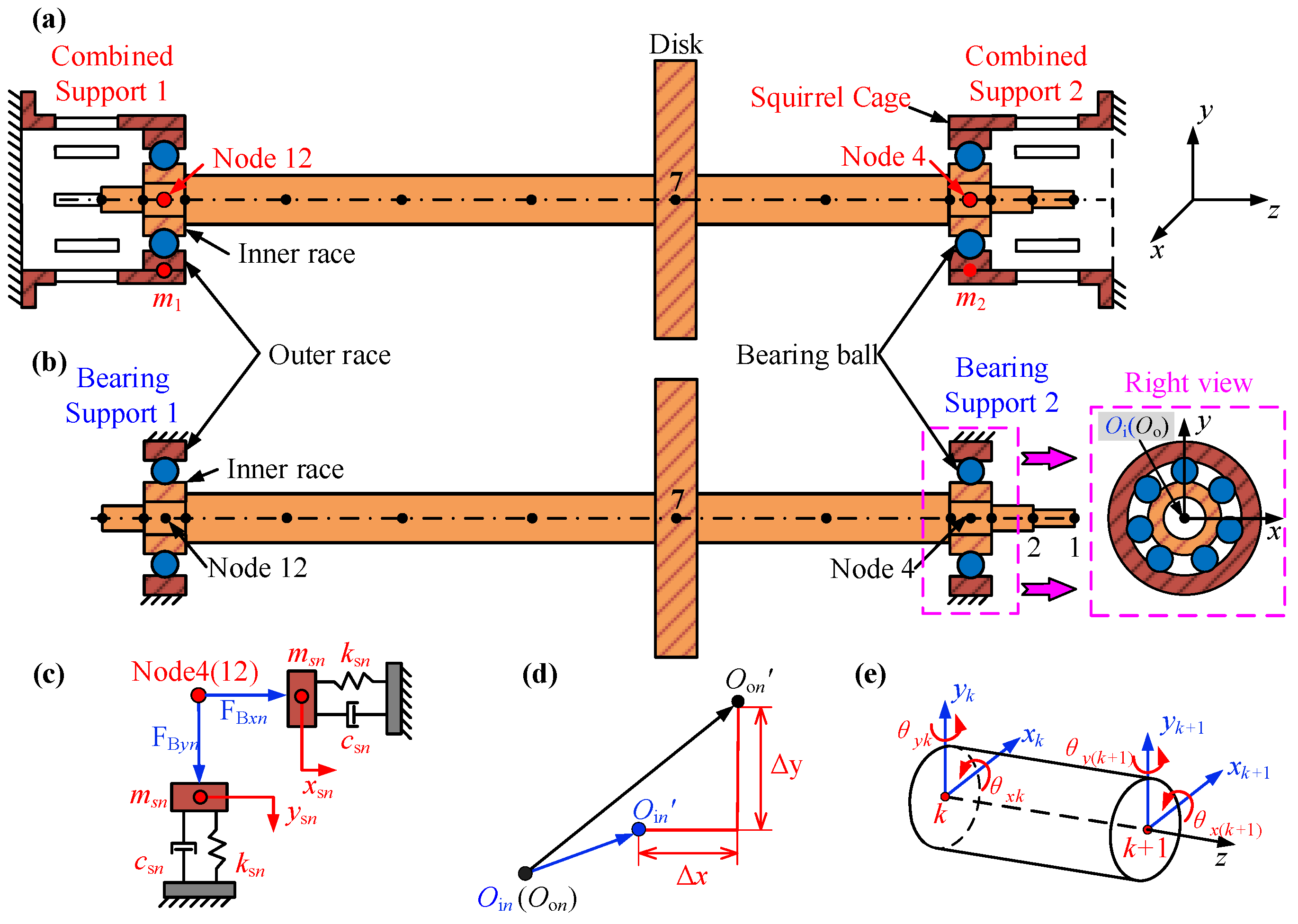
Figure 1. Sketch of a combined support-rotor system. (a) The rotor system with squirrel cages. (b) The rotor system without squirrel cages (SCs). (c) The combined support model. (d) Schematic diagram of the movement of bearing races with combined support. (e) Timoshenko beam element.
Mathematics 13 03694 g001
Figure 2. Schematic diagram of the simplified rolling bearing model.
Mathematics 13 03694 g002
Figure 3. Schematic illustration and dimensional parameters of squirrel cage.
Mathematics 13 03694 g003
Figure 4. Setup of the hammering experiment and its enlarged view.
Mathematics 13 03694 g004
Figure 5. Dynamic stiffness of the squirrel cage, calculated from the experimental results.
Mathematics 13 03694 g005
Figure 6. Measurement of the mass of squirrel cage.
Mathematics 13 03694 g006
Figure 7. Time-domain responses of the rotor system under different time-step sizes and rotational speeds. (a) 0.63ωn1. (b) ωn1. (c) 1.09ωn1.
Mathematics 13 03694 g007
Figure 8. Vibration responses of bearing-only supported rotor systems. (a) Spectrum cascades of node 4 under different speeds. (b) Amplitude–frequency responses of node 8. (c) Vibration responses of node 4 at 0.63ωn1, (c-1) is the time-domain waveform, (c-2) is Poincaré map, (c-3) isfrequency spectrum. (d) Vibration responses of node 4 at ωn1. (d-1) is the time-domain waveform, (d-2) is Poincaré map, (d-3) is frequency spectrum. (e) Vibration responses of node 4 at 1.09ωn1. (e-1) is the time-domain waveform, (e-2) is Poincaré map, (e-3) is frequency spectrum.
Mathematics 13 03694 g008
Figure 9. Vibration responses of the rotor system with combined supports. (a) Spectrum cascades of node 4 under different speeds. (b) Amplitude–frequency responses of node 8. (c) Vibration responses of node 4 at 0.63ωn1, (c-1) is the time-domain waveform, (c-2) is Poincaré map, (c-3) isfrequency spectrum. (d) Vibration responses of node 4 at ωn1. (d-1) is the time-domain waveform, (d-2) is Poincaré map, (d-3) is frequency spectrum. (e) Vibration responses of node 4 at 1.09ωn1. (e-1) is the time-domain waveform, (e-2) is Poincaré map, (e-3) is frequency spectrum.
Mathematics 13 03694 g009
Figure 10. Comparison of rotor operational deflection shape under different supports. (a) Rotor orbits of all nodes. (b) Vibration amplitudes of all nodes.
Mathematics 13 03694 g010
Figure 11. Comparison of vibration acceleration under different supports.
Mathematics 13 03694 g011
Figure 12. Spectrum cascades under different speeds and bearing initial clearances with only bearing support. (a) 0 μm. (b) 5 μm. (c) 10 μm. (d) 15 μm. (e) 20 μm. (f) 25 μm.
Mathematics 13 03694 g012
Figure 13. Spectrum cascades under different speeds and bearing initial clearances with combined supports. (a) 0 μm (b) 5 μm (c) 10 μm (d) 15 μm (e) 20 μm (f) 25 μm.
Mathematics 13 03694 g013
Figure 14. Bifurcation diagrams under different bearing initial clearances with bearing supports and combined supports. (a-1a-3) Bearing support. (b-1b-3) combined support. 1–3, respectively, represent the results when the bearing initial clearance is 0 μm, 10 μm, and 20 μm.
Mathematics 13 03694 g014
Figure 15. (a) Test rig of rotor system with bearing supports. (b) The test rig of the rotor system with combined supports. (c) Layout of test positions for the accelerometer. (d) Signal acquisition system.
Mathematics 13 03694 g015
Figure 16. Comparison between the amplitude–frequency responses of the simulation and experiment (sensor 2). (a) Bearing supports. (b) Combined supports.
Mathematics 13 03694 g016
Figure 17. The measured amplitude–frequency responses of sensor 2.
Mathematics 13 03694 g017
Figure 18. The measured spectrum cascades under different speeds with different supports (sensor 2). (a) Bearing supports. (b) Combined supports.
Mathematics 13 03694 g018
Figure 19. Comparison of measured rotor orbits under different supports.
Mathematics 13 03694 g019
Figure 20. Comparison of measured vibration accelerations under different supports. (a) Horizontal direction. (b) Vertical direction.
Mathematics 13 03694 g020
Table 1. Physical parameters of the SC.
Physical ParameterValue
ksn (N/m)See Figure 5
csn (Ns/m)56
msn (kg)1.04
Table 2. Geometric parameters of the rotor system.
ElementLength/mmOuter Radius/mmElementLength/mmOuter Radius/mm
125215–714428
225238–1014428
3102511,121025
41025131323
Table 3. Physical parameters of the bearing.
Physical ParameterValue
contact stiffness kb (N/m)13.34 × 109
Number of balls N7
Radius of outer race R (mm)62
Radius of inner race r (mm)25
radial clearance r0 (mm)0.01
Disclaimer/Publisher’s Note: The statements, opinions and data contained in all publications are solely those of the individual author(s) and contributor(s) and not of MDPI and/or the editor(s). MDPI and/or the editor(s) disclaim responsibility for any injury to people or property resulting from any ideas, methods, instructions or products referred to in the content.