Abstract
This paper proposes a coefficient-based method for designing a rocket angular stabilization system that yields an explicit, direct solution for determining the parameters of a PID control law from specified stability and performance indices. Linearized equations of motion in the yaw channel with a PID law are formulated, and the system transfer function and its characteristic polynomial are obtained. Quantitative stability and performance indices are introduced, defined via the coefficients of the characteristic polynomial, and expressed directly through the control law parameters. Based on sufficient conditions for stability and performance, resolving inequalities are derived for the control parameters that meet the prescribed stability and performance requirements. It is shown that the solution set of these inequalities is non-empty; i.e., the problem of finding the required control law parameters always has a solution. In the control-parameter space, the boundaries of the system’s stability and performance regions are explicitly described. A decomposition method and its extension are proposed for the design problem by the required transient process shape and transient time, splitting it into two sequential subproblems: obtaining the required shape and obtaining the required speed. A simple and effective adaptive algorithm is proposed to maintain constant stability and performance indices under variable engine thrust. The results of applying the proposed design methods to the development of a rocket angular stabilization system test stand are presented. Numerical experiments convincingly demonstrate the high effectiveness of the proposed coefficient-based design method—combining sufficient stability and performance conditions with the decomposition approach—for designing the test stand system.
MSC:
93D15; 93C05; 93D20; 70Q05
1. Introduction
Modern research on rocket control with variable engine thrust encompasses a wide range of methods and approaches. Scientific studies have examined classical controllers (PID, LQR) [1,2,3,4,5], as well as modern adaptive [6,7,8,9,10] and predictive [11,12] algorithms. Considerable attention has been devoted to sliding mode control [6,7,13], feedback linearization [3,5,6,7], backstepping [3,13], and their combinations, which enhance the stability and performance margins of control systems.
In [1], the application of and adaptive LQR methods for controlling a liquid rocket engine with variable thrust was investigated. To evaluate their effectiveness, mathematical models were developed and numerical experiments were conducted, accounting for thrust profile variations and external disturbances. The results showed that both methods provide a system response time of less than one second, high tracking accuracy with a small steady-state error (no more than 2%), and sufficient robustness to model uncertainties.
In [2], the use of robust control was studied, demonstrating that the system exhibits global asymptotic stability and guaranteed performance of transient processes. In [3], a PID law with robust stability and performance guarantees is proposed through an LMI formulation. Numerical experiments confirm stable attitude tracking under disturbances, validating the adequacy of the chosen synthesis in ensuring performance indices.
In [4], LQR, LQG, and PID laws are compared on a linearized model of a finless rocket for the pitch channel with thrust vector control (TVC). It is shown that PID better handles disturbances and uncertainties, reducing steady-state error. Evaluation is based on overshoot, rise, and transient times, and steady-state errors. In [5], an algebraic procedure for assigning Q and R in accordance with target time-domain indices is proposed, making performance criteria directly controllable at the synthesis stage.
In [6], the use of adaptive sliding mode control based on the feedback linearization method was considered for stabilizing a guided rocket during the initial flight phase. The study demonstrated that the proposed method ensures stable rocket orientation, reduces the amplitude of angular oscillations, and improves the performance of transient processes.
In [7], the effectiveness of different control methods—PID, LQR, and backstepping—was compared for the stabilization of a small launch vehicle with thrust vector control. Simulation results showed that backstepping and its adaptive modifications provide better stability and higher performance of transient processes than linear approaches, particularly under significant disturbances. In [8], an adaptive feedback linearization method with a two-level control structure was proposed for a suborbital rocket. Numerical results confirmed that the proposed approach guarantees asymptotic system stability, high tracking accuracy, and minimal need for parameter retuning under varying engine thrust profiles. In [9], a pitch-plane trajectory control solution for suborbital launch vehicles based on adaptive feedback linearization was introduced. The authors developed a nonlinear system model and proved the global asymptotic stability of the closed-loop system using Lyapunov functions. In [10], Adaptive Augmented Control was investigated on “frozen” LTI models. The study proposed auto-tuning of adaptive coefficients and provided recommendations for spectral damping filters.
In [11], the application of the Model Predictive Control (MPC) method to the problem of angular stabilization of a rocket with variable thrust was examined. Numerical experiments demonstrated that MPC provides high orientation stabilization accuracy, accounts for nonlinear dynamics, and maintains system stability under varying thrust profiles. In [12], an optimal thrust vector control method for an electric prototype of a small rocket based on MPC was proposed. Simulation and experimental results confirmed that MPC ensures system stability, optimal distribution of control inputs, and reduced angular oscillations. Studies [3,5,6,7,13] investigate combinations of sliding mode control, feedback linearization, and backstepping methods. More broadly, MPC is widely used to handle state and control-input constraints—including UAV payload transportation and LPV-based tracking with previewing—demonstrating convenient horizon design and constrained QP formulations [14,15].
Overall, the analysis of the approaches and methods presented in the reviewed works indicates a general trend toward the development of control systems capable of maintaining stability and transient performance under variations in engine thrust, mass distribution, and aerodynamic disturbances. Most authors emphasize that combining adaptive and robust control strategies with mathematical modeling and experimental validation is essential for ensuring the reliability and effectiveness of rocket angular stabilization systems. However, all of the considered approaches share a key limitation: they do not provide a direct synthesis of control laws based on prescribed stability and performance indices. In particular, they lack explicit analytical relationships between controller parameters and the desired stability and quality characteristics of the system. Instead, controller tuning is typically performed indirectly, using iterative optimization procedures or stability and performance analysis to search for suitable parameters.
For the control system design problem, explicit dependencies of controller parameters on stability and performance indices are highly desirable. Except for the simplest cases, such dependencies are difficult to obtain when using time- or frequency-domain specifications. By contrast, the design task becomes significantly more tractable when the requirements are formulated in the coefficient domain [16,17], since the coefficients of the characteristic polynomial of the control system are directly linked to its physical parameters.
By formulating stability and performance indices in the coefficient domain, it is, in principle, always possible to derive a system of algebraic inequalities with respect to the unknown parameters of the control law. Solving this system yields a mathematical description of the boundary of the stability and performance regions in the control law parameter space. However, for high-order systems with a large number of unknown control law parameters, these inequalities become too complex, which makes their direct use in design practically infeasible. This creates the need for less precise but simpler stability and performance conditions, which in this context are understood as sufficient conditions only.
The use of sufficient conditions for stability and performance of a control system geometrically corresponds to replacing the exact stability or performance region in the n-dimensional space of control law parameters with another region located inside the exact one. In this case, the equations describing the exact boundary may be excessively complex, while the boundary equations associated with sufficient conditions are much simpler in form [16]. Moreover, the use of sufficient conditions for stability and performance in the control system design process is particularly important, as it guarantees the fulfillment of the specified requirements with an additional safety margin, thereby significantly reducing the sensitivity of the system to parameter variations and uncertainties.
In the study of stability and performance of automatic control systems with nonstationary plants, a single system with time-varying parameters is replaced by a set of systems with constant parameters “frozen” according to one principle or another [16,18]. A “frozen” dynamic parameter of a nonstationary control system is a parameter whose value is time-varying, but does not change so rapidly that its change over the transient process in the system alters its character; that is, for each finite time interval one can find constant values of the control law parameters that ensure the stability and performance of the system on this time interval. In this case, the hypothesis is used that if all “frozen” systems are stable, then the original nonstationary system is also stable. In the design of real systems, the use of sufficient conditions ensures not merely the stability and performance of the “frozen” systems, but their stability and performance with some margin, and therefore, the conclusion of the hypothesis usually proves to be true. The set of “frozen” systems is usually called a multiregime system.
The design of multiregime systems differs substantially from the design of stationary ones. If the control system is stationary, i.e., the parameters of the controlled object are constant in time, then there is no need to update the control law parameters, and they can be taken as constant. If the control system is nonstationary, i.e., the parameters of the object change over time, then the entire interval of variation of the parameters of the controlled object is divided into m subintervals, and for each of them, such values of the control law parameters are determined as to ensure the stability and performance of the control system on that subinterval. Therefore, traditional design methods become too cumbersome, since one has to solve the design problem of m stationary automatic control systems with “frozen” parameters for m different plants, where m is the number of regimes used in the design. The aforementioned sufficient conditions for stability and performance of automatic control systems make it possible to substantially increase the length of the sub-intervals and thereby significantly reduce the number of regimes m over the entire interval of variation of the parameters of the controlled object. The coefficient-based approach in combination with sufficient conditions for stability and performance was developed by the authors of [16] precisely to eliminate these difficulties of analysis and design of multiregime control systems.
The coefficient-based approach to control system design, combined with sufficient conditions for stability and performance, was applied by the authors of this paper to the design of an angular stabilization system for a satellite actuated by reaction wheels [17], and to a rocket angular stabilization system controlled by aerodynamic fins [19,20]. The results obtained indicate the high effectiveness of the coefficient-based approach in combination with sufficient stability and performance conditions for angular stabilization system design.
This paper addresses the development of a design method for control systems that enables solving the problem of direct computation of control law parameters from quantitative stability and performance indices. As a solution to this problem, a coefficient-based method is proposed for designing a rocket angular stabilization system according to specified stability and performance indices. Linearized equations of the angular stabilization system motion in the yaw channel with a PID control law are formulated, and the angular stabilization system transfer function and its characteristic polynomial are derived. Quantitative stability and performance indices of the angular stabilization system are introduced, defined via the coefficients of the characteristic polynomial, and expressed directly through the physical parameters of the angular stabilization system. Based on sufficient conditions for stability and performance, resolving inequalities are constructed and analyzed for the control law parameters corresponding to the prescribed stability and performance requirements.
A decomposition method is proposed for the angular stabilization system design problem by the required transient process shape and transient time, splitting it into two sequential subproblems—obtaining the required shape and obtaining the required speed—together with an extension of this method. A simple and effective adaptive algorithm is considered to ensure constant stability and performance indices of the angular stabilization system by varying the control law parameters according to the throttle coefficient of the engine thrust.
Results are presented for applying the coefficient-based design method and the decomposition method to the development of a rocket angular stabilization system test stand. In the control-parameter space, the stability and performance regions of the angular stabilization system are constructed. Numerical experiments convincingly demonstrate the high effectiveness of the proposed coefficient-based design method—combining sufficient stability and performance conditions with the decomposition approach—in the practical design of the angular stabilization system test stand.
In Section 2 of the paper, the mathematical model of the rocket angular stabilization system in the yaw channel with a PID control law, obtained on the basis of linearized equations of motion, the transfer function of the rocket angular stabilization system, and its characteristic polynomial are presented.
In Section 3, quantitative stability indices of the rocket angular stabilization system are introduced, which are defined via the coefficients of the characteristic polynomial of the rocket angular stabilization system and are expressed directly through the physical parameters of the rocket angular stabilization system. Based on sufficient conditions for stability and performance of the rocket angular stabilization system, resolving inequalities are formulated and examined with respect to the values of the control law parameters corresponding to the specified requirements for the stability of the rocket angular stabilization system; equations for the boundaries of the asymptotic stability region in the space of the control law parameters are obtained.
In Section 4, quantitative performance indices of the rocket angular stabilization system are introduced, which are likewise defined via the coefficients of the characteristic polynomial of the rocket angular stabilization system and are expressed directly through the physical parameters of the rocket angular stabilization system. Based on sufficient conditions for performance of the rocket angular stabilization system, resolving inequalities are formulated and examined with respect to the values of the control law parameters corresponding to the specified requirements for the performance of the rocket angular stabilization system; equations for the boundaries of the performance region in the space of the control law parameters are obtained.
In Section 5, the developed decomposition method is set out for the design problem of the rocket angular stabilization system by the required transient process shape and transient time into two sequentially solvable subproblems: obtaining the required transient process shape and obtaining the required speed.
In Section 6, the developed extension of the decomposition method is set out for the case when the number of control law parameters is less than the degree of the characteristic polynomial.
In Section 7, a simple and effective adaptive algorithm is set out for solving the problem of ensuring the constancy of the stability and performance indices of the rocket angular stabilization system, which changes the control law parameters depending on the values of the engine thrust throttling coefficient.
In Section 8, the results are presented of applying the coefficient-based design method that combines sufficient conditions for stability and performance and the decomposition method for the creation of a rocket angular stabilization system test stand. In the space of the control law parameters, the stability and performance regions of the rocket angular stabilization system are constructed. The results of numerical experiments convincingly demonstrate the high effectiveness, in the design of the test stand, of the proposed coefficient-based design method, which combines the use of sufficient conditions for stability and performance of the rocket angular stabilization system and the decomposition method.
2. Transfer Function of the Rocket Angular Stabilization System in the Yaw Channel
Figure 1 shows the block diagram of the yaw-channel angular stabilization system, where

Figure 1.
A block diagram of the rocket angular stabilization system in the yaw channel.
—programmed value of the yaw angle ;
—yaw angle error;
—control signals from compensating devices 1, 2, and 3;
—nozzle deflection angle from its neutral position when rotating about the yaw axis;
, , —Laplace transforms of , , respectively.
To obtain the transfer functions of the angular stabilization system elements, we use their linearized equations of motion, assuming small yaw angle deviations (if the deviations of the current yaw angle from the programmed values do not exceed 10 degrees, then the error from replacing the sine of the deflection angle with the angle itself does not exceed 0.05%). The transfer functions of the angular stabilization system elements are , which represent the transfer function of the actuator (servo motor and movable nozzle drive), where T is the time constant and p is the differentiation operator. , and are the transfer functions of the controlled object (rocket), where F is the engine thrust force, with values in the interval , where and are the minimum and maximum thrust forces; l is the distance from the thrust application point to the rocket’s center of mass; is the rocket’s moment of inertia relative to the yaw axis. are the transfer functions of compensating devices 1, 2, and 3, implementing the proportional–integral–derivative (PID) control law. The transfer function of the angular stabilization system in the yaw channel is defined by the formula:
where is the characteristic polynomial of the angular stabilization system.
The characteristic equation of the angular stabilization system, written in compact form, is:
where . To account for the variation in engine thrust F during flight, a time-dependent throttle coefficient is introduced:
where is the maximum engine thrust. Let be the throttle coefficient corresponding to the minimum thrust . Then the thrust force F and the throttle coefficient satisfy the following inequalities:
Taking (3) into account, the coefficients of the characteristic Equation (2) can be written as:
where are the control law parameters adjusted for engine thrust throttling F. Next, we will use the notation for the integer range .
For brevity and convenience, all subsequent calculations are carried out for the maximum thrust , i.e., without throttling, for which:
3. Stability Analysis of the Rocket Angular Stabilization System Based on Sufficient Conditions
We introduce stability indices expressed directly through the coefficients of the control system’s characteristic polynomial
and do not require computing its roots:
In [16], a theorem is proved implying that, for control system stability, it is sufficient that the coefficients of the characteristic polynomial satisfy the inequalities:
or
In our case, the angular stabilization system characteristic polynomial has order , so there are two auxiliary stability indices:
By substituting these equalities into the expressions for the coefficients of the characteristic polynomial (5), we obtain the following expressions for the dependence of the stability indices on the unknown control law parameters :
For asymptotic stability of the angular stabilization system with characteristic polynomial (1), it is sufficient that the following inequalities hold:
For the stability indices , the conditions for mean that all roots of the characteristic polynomial will have negative real parts; i.e., all roots will be located in the left half of the complex root plane.
Solving (9) with respect to gives:
This system of two inequalities contains three unknowns ; hence, one of them can be chosen freely, e.g., (Section 4 below shows that is constrained by the performance indices). Then, from the second inequality, one can express via and, from the first inequality, express via and . To ensure asymptotic stability of the angular stabilization system, it suffices that satisfy (10). If is taken as the free parameter instead of , the system (10) for and becomes:
Evidently, for any positive free choice of or , each of the systems (10) and (11) admits an infinite set of solutions with positive or , respectively.
4. Performance Analysis of the Rocket Angular Stabilization System Based on Sufficient Conditions
We introduce the performance indices of the angular stabilization system, which are expressed directly through the coefficients of the characteristic polynomial (1) and do not require computing its roots:
For the fourth-order characteristic polynomial of the angular stabilization system , there are three performance indices , which can be written in terms of the unknown control law parameters :
We impose the requirement that the transient process of the angular stabilization system be non-oscillatory (aperiodic). The sufficient conditions for aperiodicity of the transient process according to [16] are:
Substituting (12), we obtain three inequalities for the unknown parameters :
For the performance indices , the conditions for mean that all roots of the characteristic polynomial will be negative and real; i.e., all roots will lie on the real axis in the left half of the complex root plane.
Solving this system of three inequalities with respect to ensures the aperiodicity of the angular stabilization system’s transient processes. From (13) the following applies:
- depends only on the physical parameters ;
- depends on and the parameters ;
- depends on and .
This leads to the following sequential algorithm for solving (13):
- From the inequality for , determine the maximum admissible value of :
- Using the obtained value of , determine the maximum admissible value of from the inequality for :
- Using the obtained values of and , determine the maximum admissible value of from the inequality for :
Thus, for any positive value of satisfying (14), the solution set of inequalities (14)–(16) with positive and is non-empty. As noted in Section 3, the restriction on is imposed by inequality (14) for the performance index .
5. Decomposition of the Rocket Angular Stabilization System Design Problem by Required Transient Process Shape and Transient Time
The performance indices of the angular stabilization system, introduced in Section 4, determine only the shape of the transient processes, since they are dimensionless and remain unchanged under time scaling. That is, like normalized coefficients of the characteristic equation, they do not characterize system speed but only the form of the transient response. In [16], it was shown that the performance indices are analogs of the normalized coefficients A and B of Vyshnegradsky’s diagram [18], and they can always be used to identify the sector within which all the roots of the characteristic polynomial lie, as well as to obtain an estimate of the oscillatory behavior of the angular stabilization system. These properties make it possible, when transforming the characteristic equation into normalized form, to decompose the angular stabilization system design problem into two subproblems: (1) achieving the required transient process shape, and (2) achieving the specified transient time. To move to the normalized characteristic equation, we use the concept of the geometric mean root [18] of the characteristic Equation (2):
where are the roots of the characteristic Equation (2).
The larger the geometric-mean root , the farther the roots of the characteristic equation are from the real axis of the root plane, and the faster the terms of the transient process decay; that is, the geometric-mean root physically characterizes the speed (quickness) of the control system.
Introducing the new complex variable s by substituting , we obtain the normalized characteristic equation of the angular stabilization system:
where are dimensionless coefficients that do not change with time scaling, meaning they characterize only the transient process shape of the angular stabilization system, but not its speed. Express the coefficients of the normalized characteristic Equation (18) in terms of the control law parameters :
Returning to the original complex variable, the characteristic Equation (2) becomes
The geometric-mean root can serve as a measure of the speed of the transient processes. Using the normalized characteristic Equation (18) makes it possible to construct the transient process of the angular stabilization system in the non-dimensional time , in which the process shape remains unchanged under time scaling. Thus, at the first stage of selecting the control law parameters, one can abstract from the speed requirements and solve the problem of achieving the required transient process shape independently of the speed requirements. If the transient process performance in non-dimensional time satisfies the shape requirements (13), then the required speed of the transient process in absolute time t can be ensured by choosing an appropriate , i.e., by rescaling time. The time scale is chosen from
where and are the transient time of the angular stabilization system in relative and absolute time, respectively. The transient time in non-dimensional time is determined from the transient process plot in , while the required transient time in absolute time is specified by the angular stabilization system synthesis requirements. If for the normalized characteristic Equation (18) there exist control law parameters , such that the transient process shape in non-dimensional time meets the requirements (13), then for the characteristic Equation (20) in absolute time t, the parameters are determined via the time scale . Taking into account expressions (5) for the coefficients of (2), we obtain
which follow from comparing (19) for the coefficients of the normalized characteristic Equation (18) with (2) for the coefficients of the angular stabilization system characteristic equation.
6. Extension of the Decomposition Method for Control System Synthesis
As follows from the form of the characteristic Equation (20), the time scale appears in four coefficients of the equation— (with )—except for the leading coefficient of the highest-order term . This means that when moving from the normalized characteristic Equation (18) to the characteristic Equation (20), all coefficients except the leading one change depending on the value of the time scale . Consequently, in the general case, the number of coefficients of the characteristic equation that depend on the time scale coincides with the degree of the characteristic equation. In the present case, the order of the angular stabilization system characteristic Equation (2) is four, but the number of coefficients that can be modified by tuning the control law parameters is three, since the coefficients do not depend on these parameters. Transforming the angular stabilization system characteristic Equation (2) yields the following:
In Equation (23), the coefficient of is constant, as it does not depend on the control law parameters . Therefore, accounting for this independence, the characteristic Equation (20) can be rewritten as:
Let us examine how the performance indices of the angular stabilization system change when transitioning from the normalized characteristic Equation (18) to the characteristic Equation (20). For Equation (18) we have:
Similarly, for Equation (20):
Comparing the expressions for the performance indices in (25) and (26), we see that they remain unchanged and do not depend on the value of the time scale . We examine how the performance indices of the angular stabilization system change when transitioning from the normalized characteristic Equation (18) to the characteristic Equation (24). For (24) we have:
Comparing the expressions for the performance indices in (25) and (27), we see that only remains unchanged, while and vary with the time scale : varies proportionally to , and is inversely proportional to . Let us decrease by one the power of the time scale in the normalized characteristic Equation (24):
We now check how the performance indices change when transitioning from the normalized characteristic Equation (18) to (28). For (28) we obtain:
Comparing (25) and (29), we see that and remain unchanged, while only varies, inversely proportional to the value of the time scale . Thus, the transition from the normalized characteristic Equation (24) to the normalized characteristic Equation (28) drastically reduces the dependence of the performance indices of the angular stabilization system on and expands the range of values over which the transient process shape is preserved under this transformation.
7. Adapting the Angular Stabilization System Control Law to Engine Thrust Throttling
As follows from expressions (5) for the coefficients of the characteristic Equation (2), the coefficients are directly proportional to the control law parameters , computed at the maximum engine thrust , and to the throttle coefficient :
If the control law parameters are kept constant, then the coefficients in (23) will decrease proportionally to the throttle coefficient . This will change the coefficients of the characteristic Equation (2) and, accordingly, the stability and performance indices of the angular stabilization system. The most effective way to keep the stability and performance indices of the angular stabilization system constant under controlled thrust is to use adaptive control, in which the parameters in (30) remain constant during throttling, . To satisfy these conditions, the products must remain constant by adjusting from the values computed at according to the current throttle coefficient . From (5) it is evident that the adapted control law parameters must be set as:
i.e., the adapted parameters must vary inversely with the throttle coefficient .
8. The Design of the Angular Stabilization System for the Rocket Test Stand
For experimental studies of the angular stabilization system dynamics, we used the technical specifications of the developed rocket test stand, as presented in Table 1.

Table 1.
Technical specifications of the rocket test stand.
The parameters and l were taken from the design documentation of the laboratory rocket test stand that was created. The design documentation was developed using the CAD Autodesk Inventor 2020.1, which automatically calculates the specified parameters. The parameter T was calculated from the electric motor’s datasheet and verified experimentally. The parameter was provided by the engine developers of the test stand on the basis of numerical calculations and physical measurements on the laboratory rocket test stand.
The mathematical model of the rocket test stand angular stabilization system in yaw corresponds to the block diagram in Figure 1. It is required to determine the control law parameters from the sufficient stability conditions (10) or (11) and performance conditions (14)–(16). To this end, one must construct the corresponding stability and performance regions of the angular stabilization system in the space of the unknown parameters , or on the plane of any two of them with a fixed third parameter, and show that the set of points in these three-dimensional regions is non-empty. To construct the angular stabilization system performance region, we use the decomposition method for the angular stabilization system design problem to (i) obtain the required transient process shape and (ii) obtain the required speed (transient time). In solving the first subproblem, we find the normalized control parameters that correspond to the coefficients of the normalized characteristic Equation (18) and ensure the required values of the transient process shape indices (13). In solving the second subproblem, we determine the time-scale factor for mapping from relative to absolute time using (21) and then, by (22), obtain the real control law parameters corresponding to the coefficients of the characteristic Equation (19), which coincides with the characteristic Equation (2). When constructing the stability region, note that, according to Section 3, each system of inequalities (10) or (11) has an infinite set of solutions corresponding to the choice of a free parameter value or . As noted in Section 3, the constraint on is set by inequality (14) for the performance index . The constraint on is set by inequality (16) for the performance index ; thus, to use this inequality, one must sequentially solve all three inequalities (14)–(16) for . As shown below in Section 8.1, in this case it is more convenient to proceed by solving all three inequalities (14)–(16) under conditions (13) and using their solution with respect to the parameter :
To construct the stability and performance regions of the angular stabilization system, we adopt the boundary value .
8.1. Construction of the Stability Region
Let us solve inequalities (11) with respect to and the product involving and , taking the boundary value :
The corresponding boundaries of the stability region are described by:
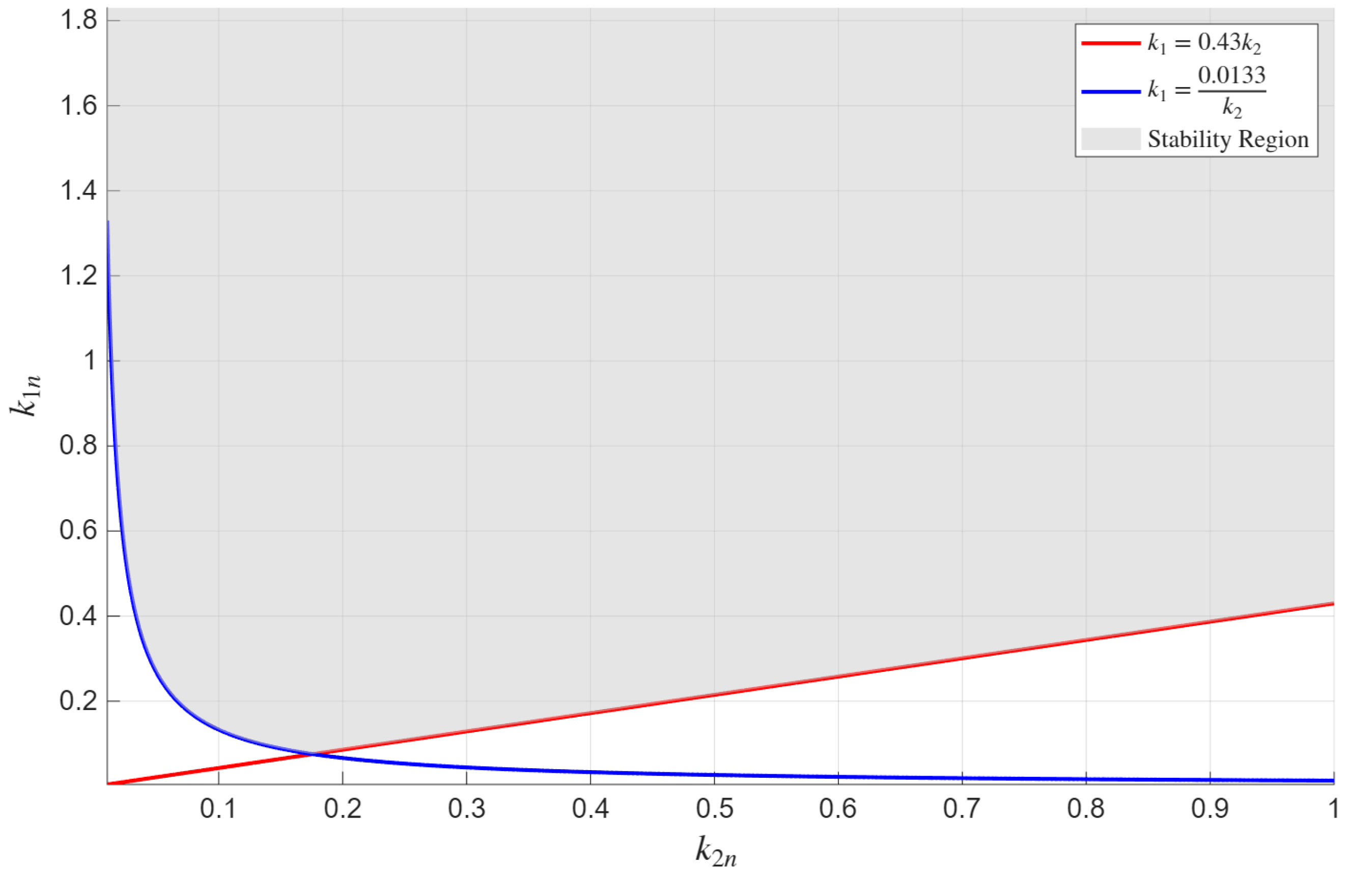
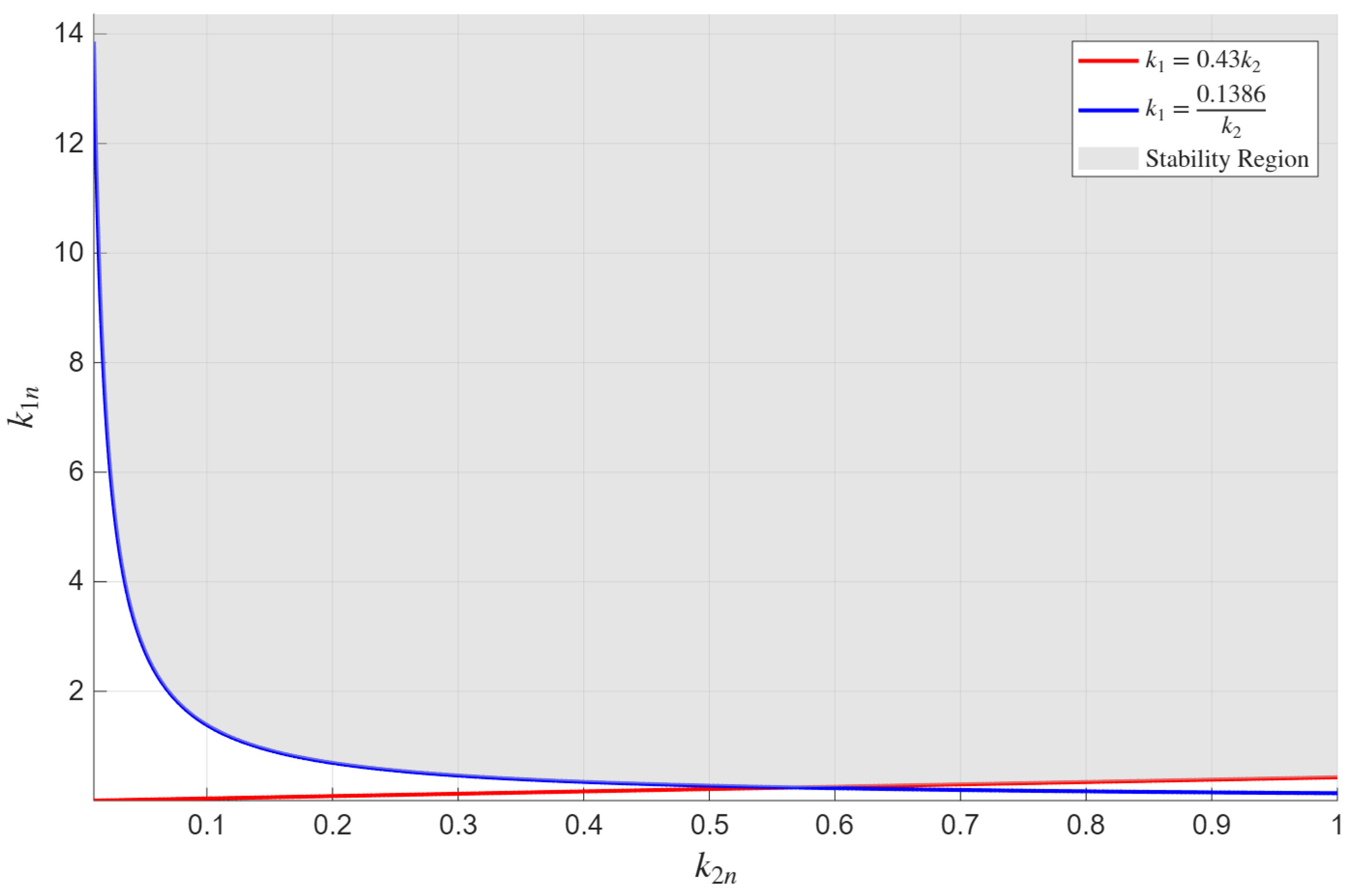
The region of asymptotic stability of the angular stabilization system and its boundaries on the plane for , corresponding to inequalities (33) and equalities (34), are shown in Figure 2.
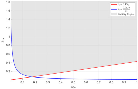
Figure 2.
Stability region of the angular stabilization system on the () plane at .
8.2. Construction of the Performance Region
Determine the coefficients of the normalized characteristic Equation (18) corresponding to the boundary values (32) of the control law parameters :
The roots of the normalized characteristic Equation (18) with coefficients given by (35) are:
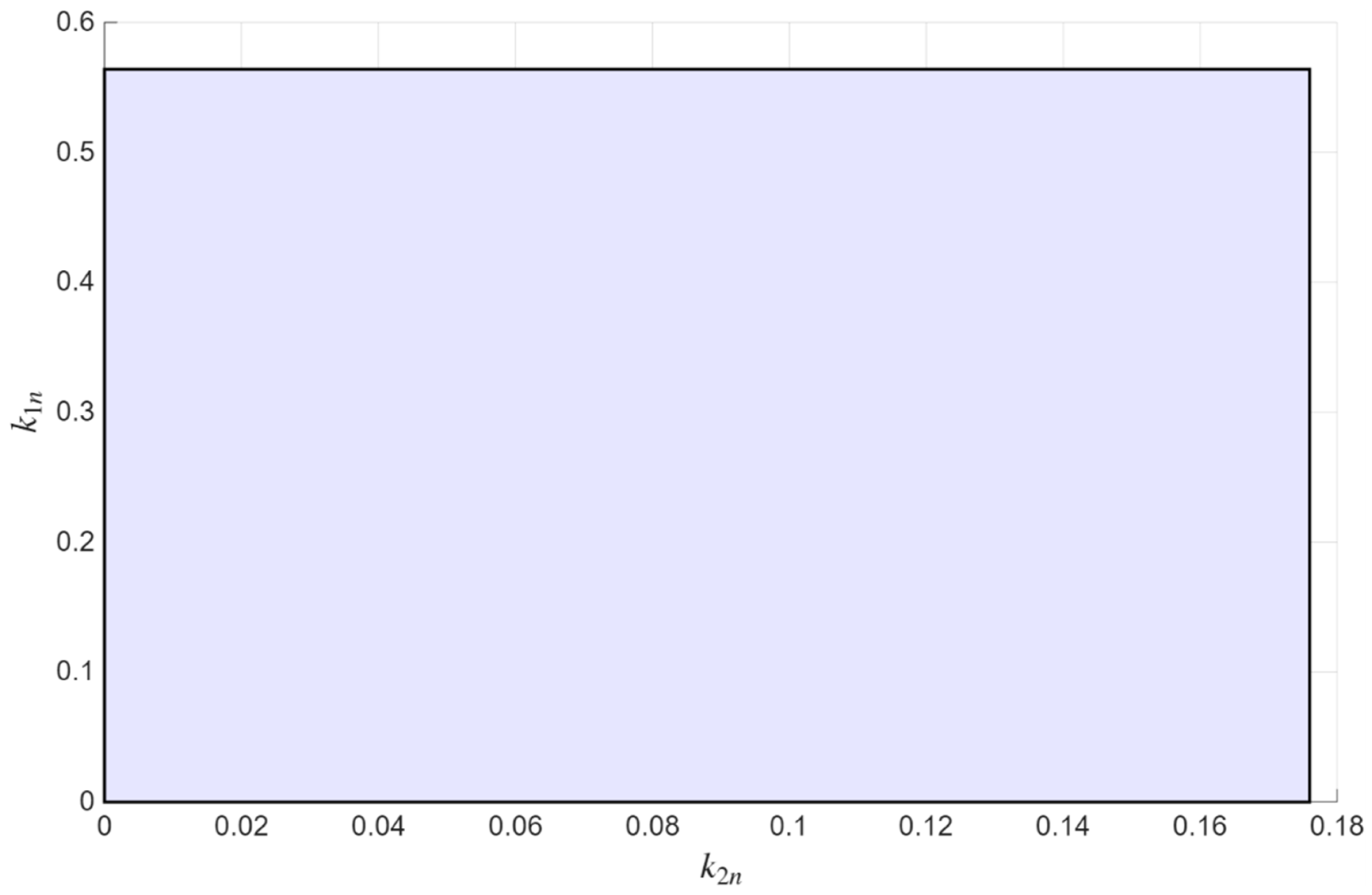
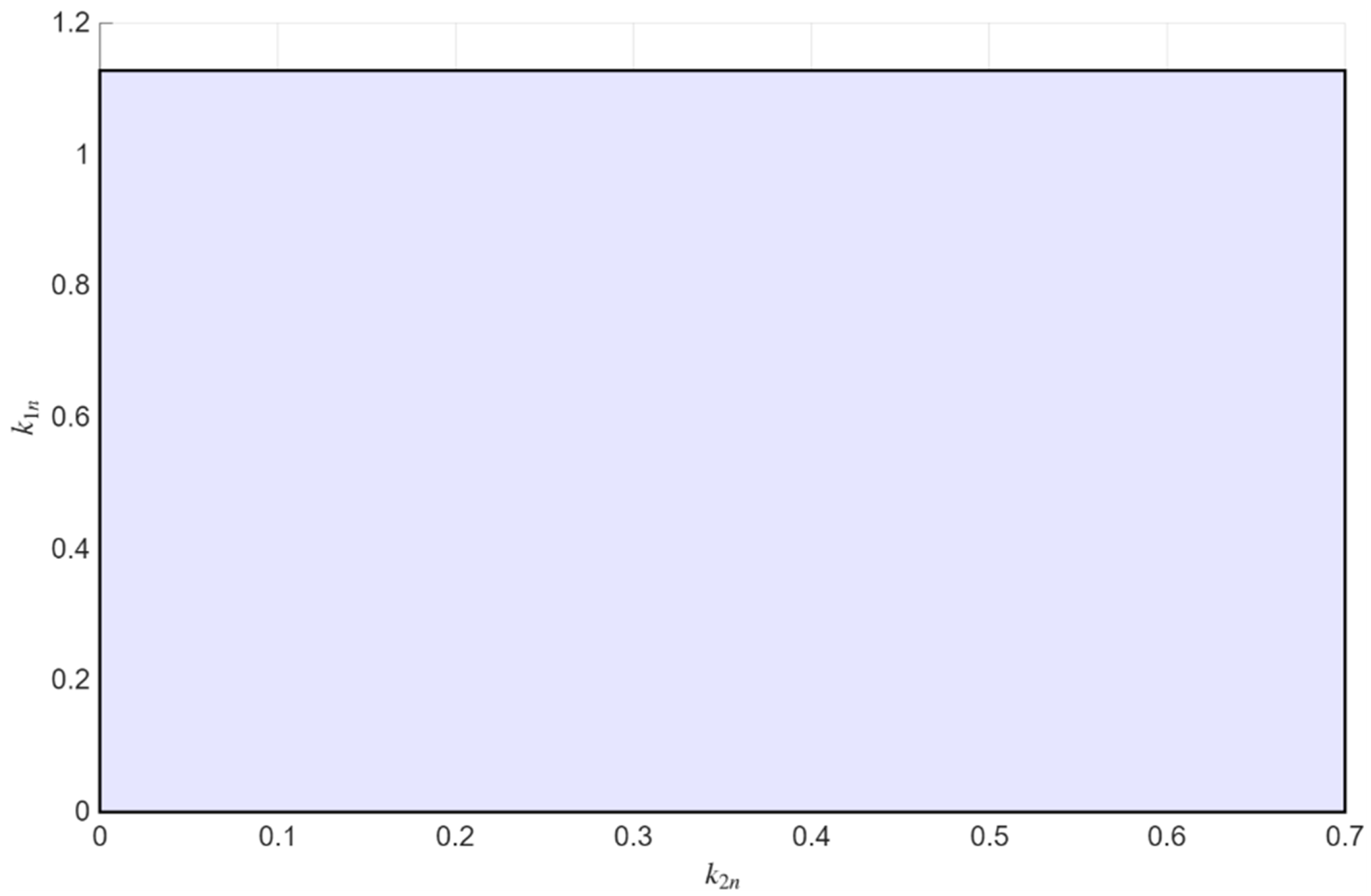
The rectangular region in Figure 3 defined by the inequalities
is the performance region of the angular stabilization system for . Within this region, the performance indices of the angular stabilization system satisfy inequalities (13), i.e., the transient processes of the angular stabilization system are aperiodic.
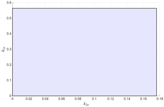
Figure 3.
Performance region of the angular stabilization system on the plane at .
The results of calculating the stability and performance indices of the angular stabilization system at engine thrust are given in Table 2. As follows from Table 2, both the sufficient stability conditions (11) and the sufficient performance conditions (13) are satisfied. Moreover, comparing the stability indices and from Table 2 with the sufficient stability conditions (9) shows that these conditions are met with a large margin.

Table 2.
Results for stability and performance indices of the angular stabilization system.
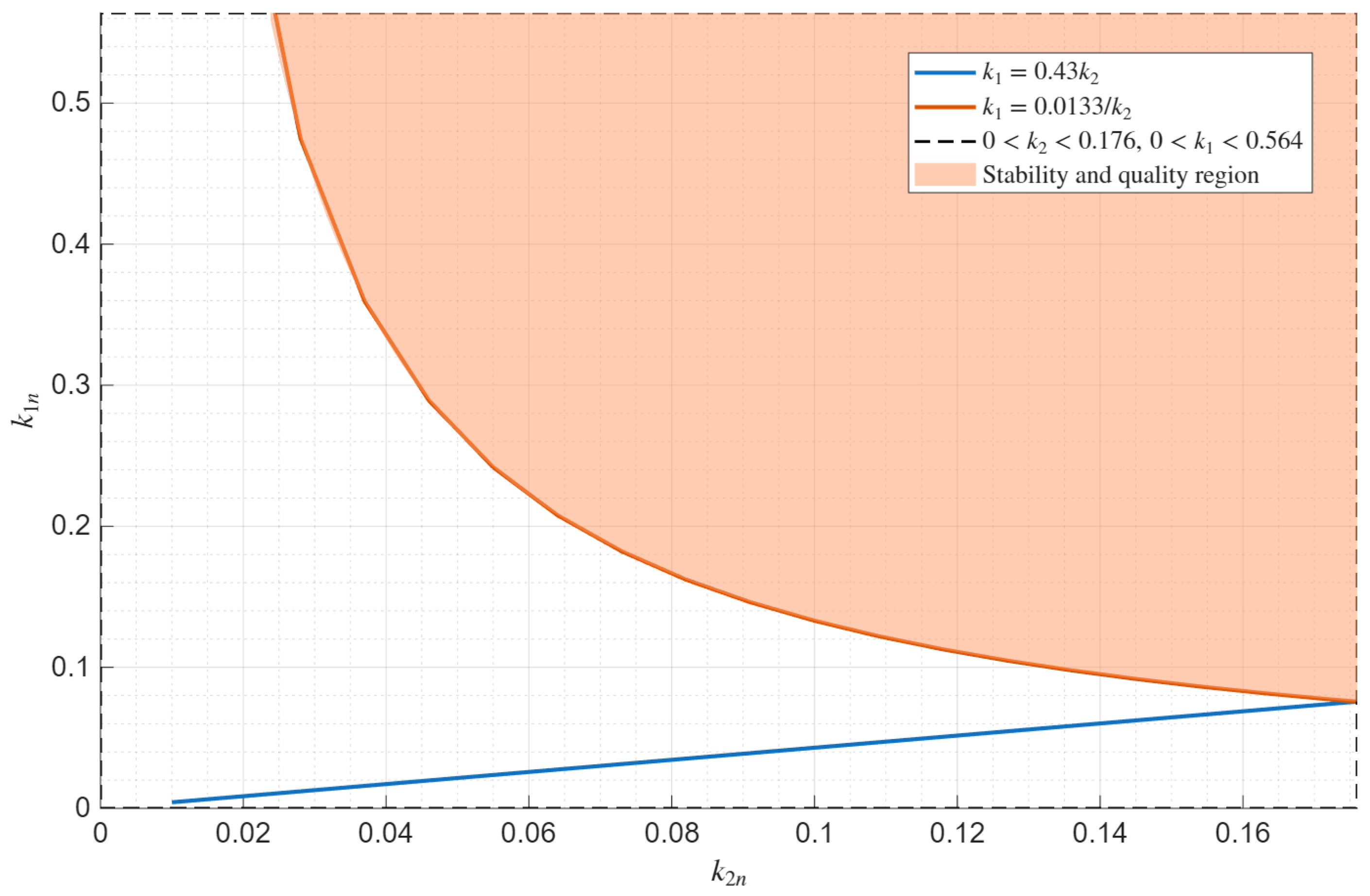
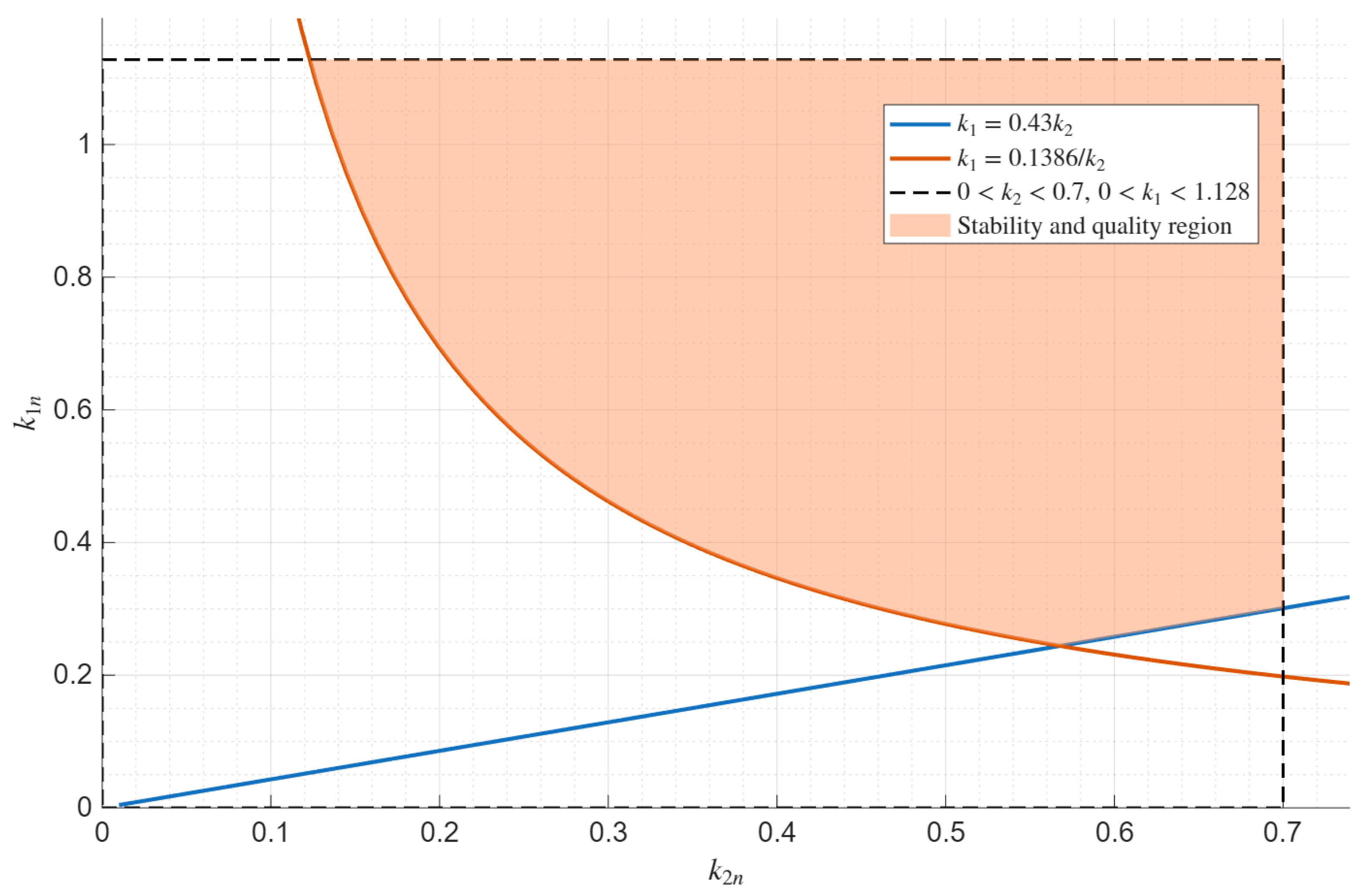
Figure 4 shows the stability and performance region of the angular stabilization system, defined as the intersection of the stability region with the performance region. As can be seen from the figure, this region is non-empty.
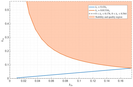
Figure 4.
Stability and performance region of the angular stabilization system on the () plane at .
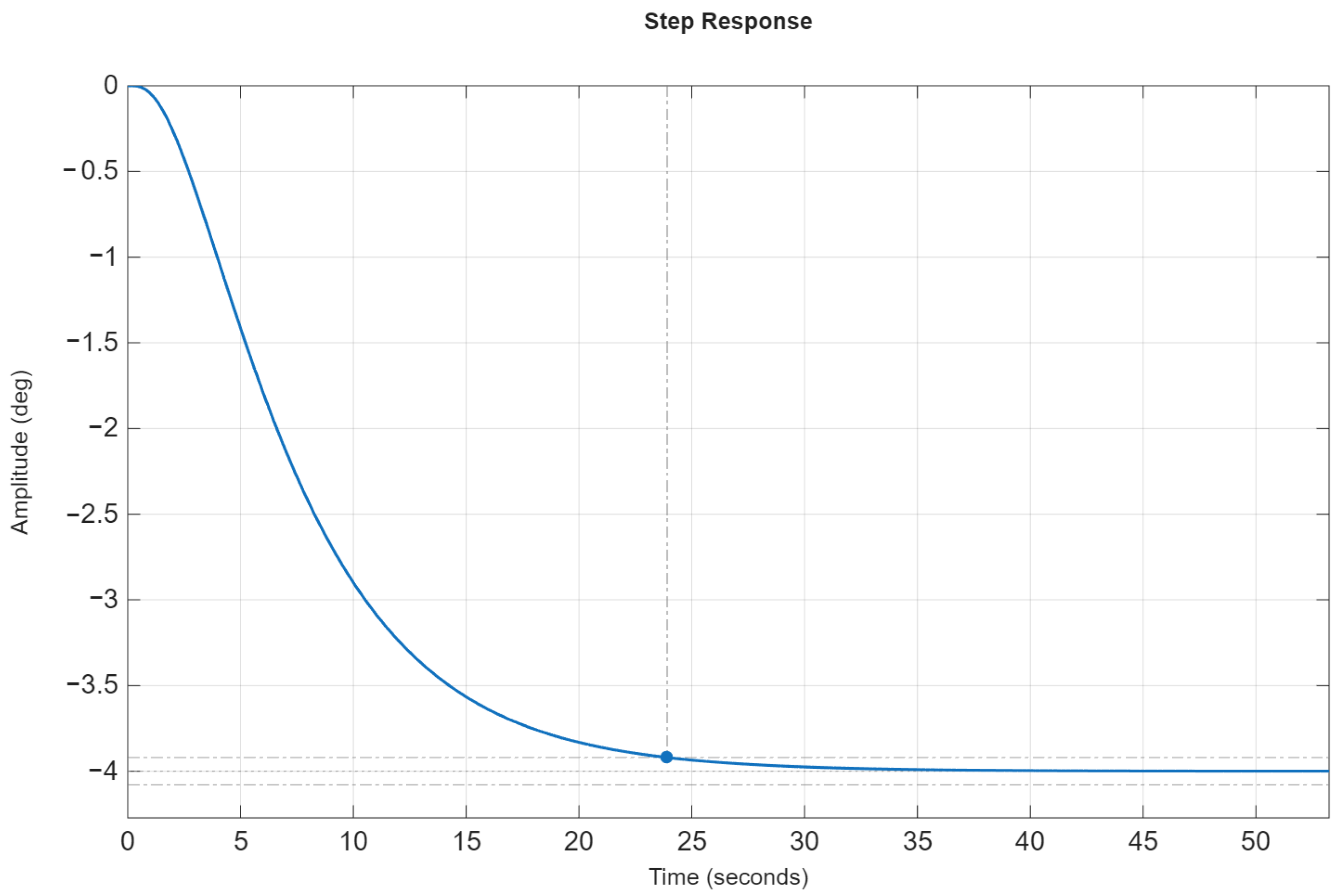
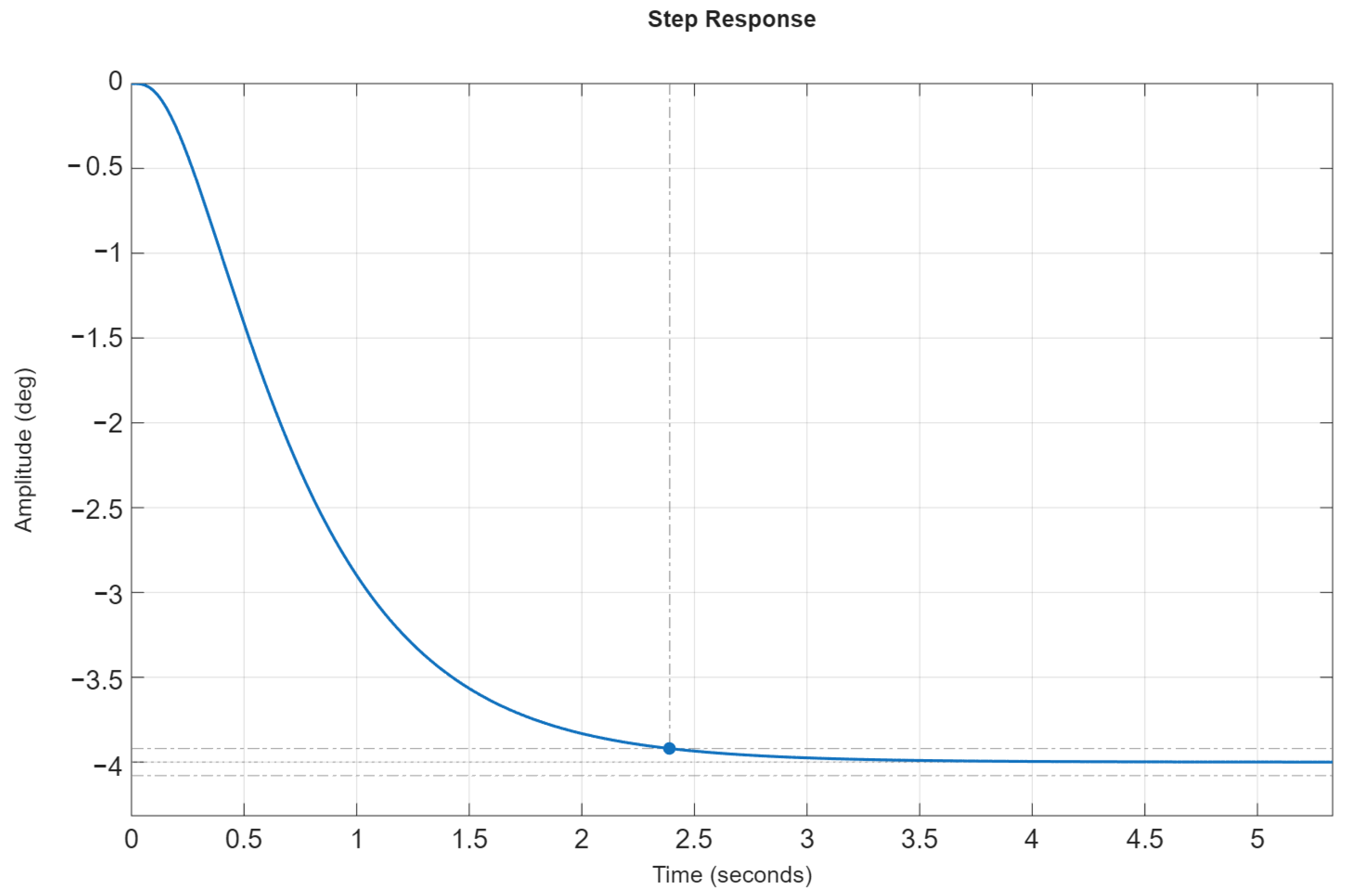
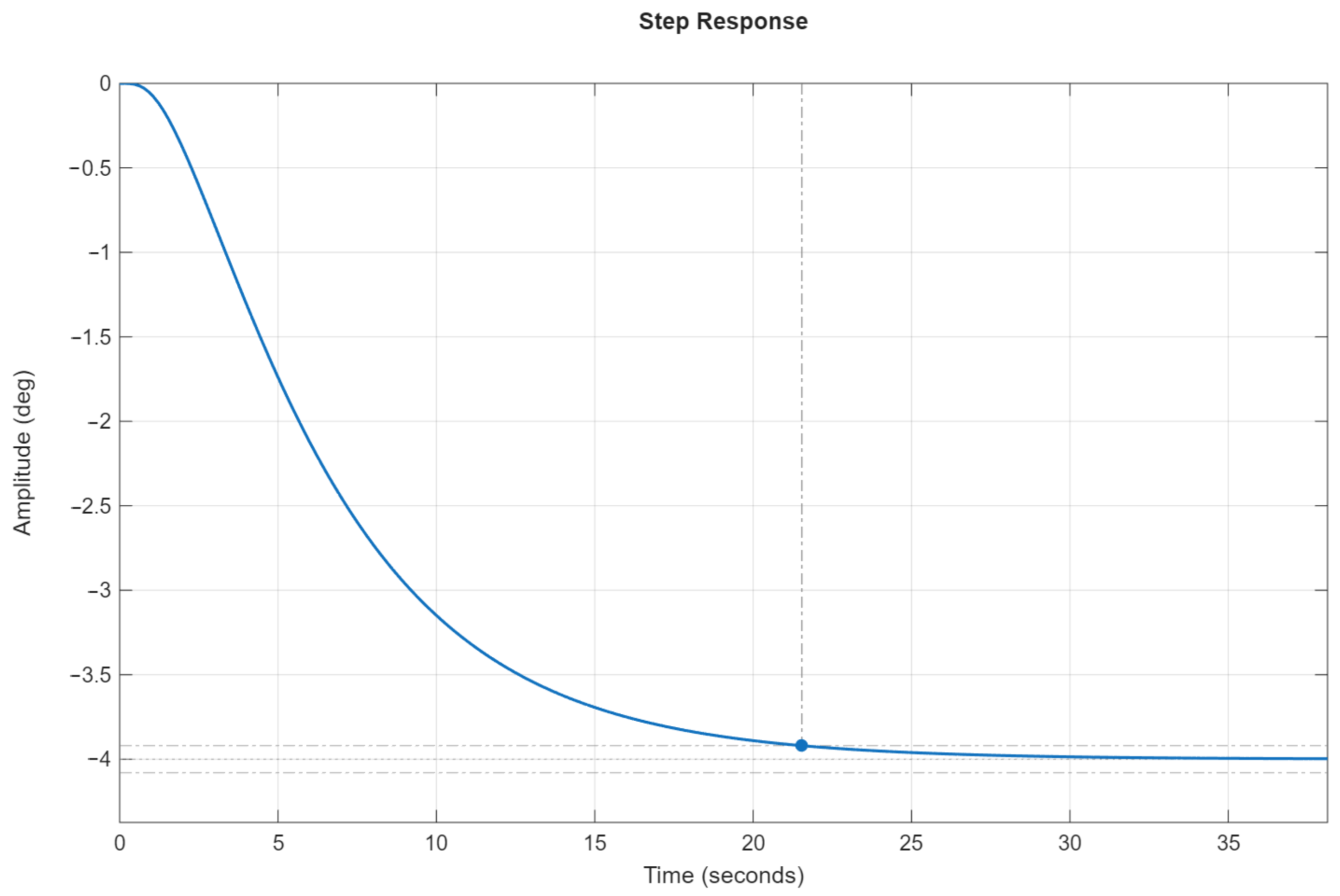
Figure 5 shows the transient process of the angular stabilization system in non-dimensional time at , whose shape demonstrates compliance with the sufficient stability and performance conditions. The transient time in non-dimensional time is s.
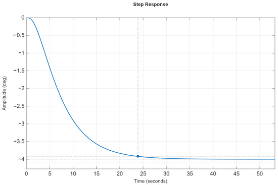
Figure 5.
The transient process of the angular stabilization system in non-dimensional time.
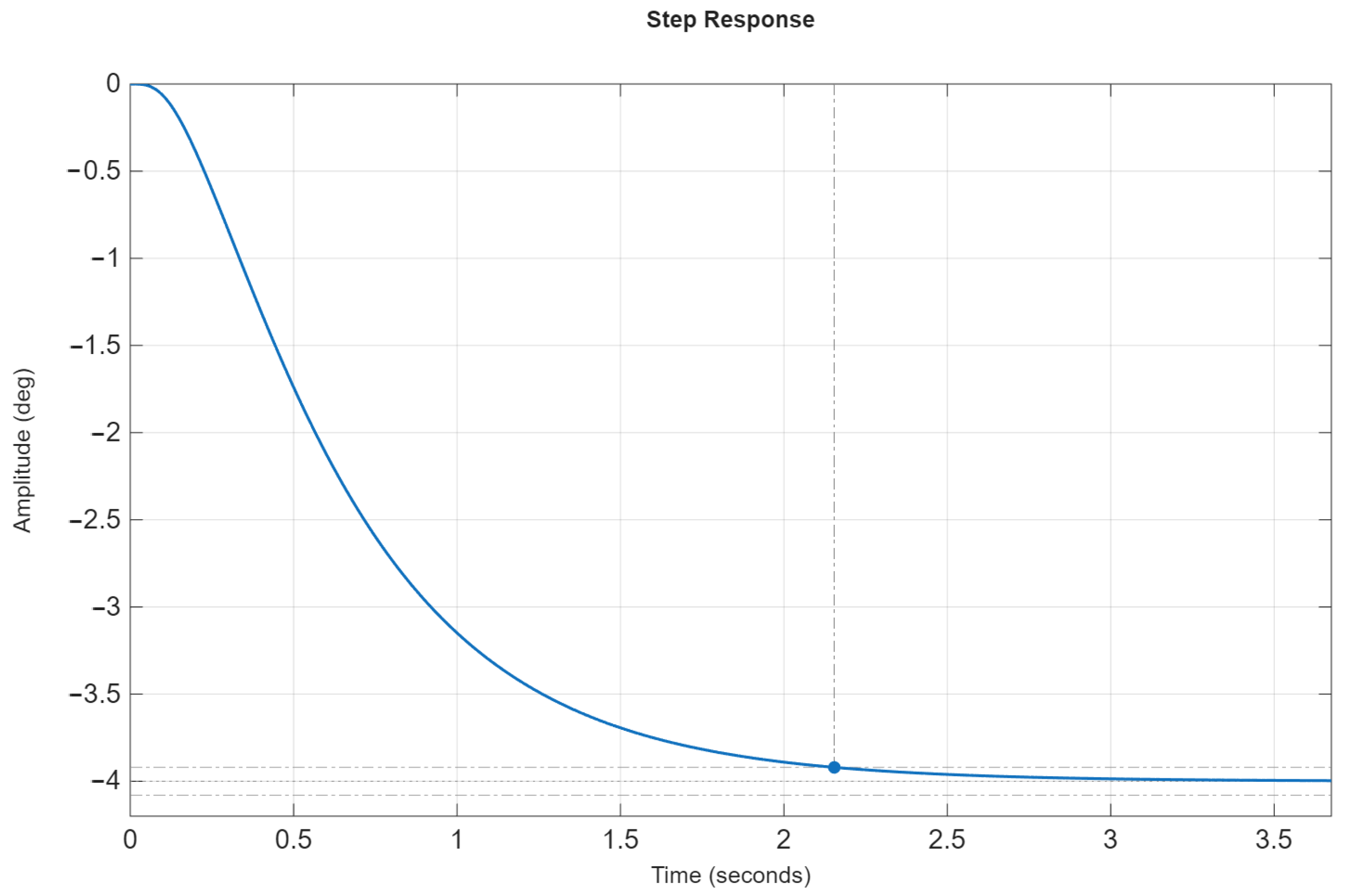
Assume that, according to the angular stabilization system design requirements, its speed must be increased by a factor of 10; that is, the transient time in absolute time must not exceed s. The time-scale factor according to (21) should be . The control law parameters for the transient process in absolute time are determined from (22):
Accordingly, the characteristic Equation (20), taking (35) into account, becomes:
Figure 6 shows the transient process of the angular stabilization system in absolute time corresponding to the characteristic Equation (37). Comparing the transient plots in Figure 5 and Figure 6 shows that the transient process shape remains unchanged, while the transient time decreases by a factor of 10, i.e., the speed increases tenfold.
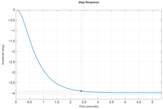
Figure 6.
The transient process of the angular stabilization system in absolute time.
8.3. Increasing the Speed of the Angular Stabilization System
To increase speed (reduce the transient time ), one may relax the requirement of an aperiodic transient process and allow oscillations. To this end, we weaken the requirement on the performance index , replacing inequalities (13) with:
Find the control law parameters corresponding to the coefficients of the normalized characteristic Equation (18) that ensure the required transient process shape indices (38):
For constructing the stability region, set the boundary value . Solve inequalities (11) with respect to and the product involving and , taking :
The corresponding stability region boundaries are described by:
The region of asymptotic stability of the angular stabilization system and its boundaries on the plane for , corresponding to (40) and (41), are shown in Figure 7.
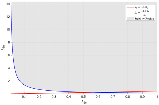
Figure 7.
The stability region of the angular stabilization system on the plane at .
To construct the performance region of the angular stabilization system, determine the coefficients of the normalized characteristic Equation (18) at the boundary values (34) of the control law parameters :
The roots of the normalized characteristic Equation (18) with coefficients given by (42) are:
The rectangular region in Figure 8 defined by
is the performance region of the angular stabilization system for . Within this region, the performance indices satisfy (38), meaning the transient processes may be oscillatory, since the aperiodicity requirement via has been relaxed. Figure 9 shows the stability and performance region of the angular stabilization system, defined as the intersection of the stability region with the performance region. As can be seen, this region is non-empty.
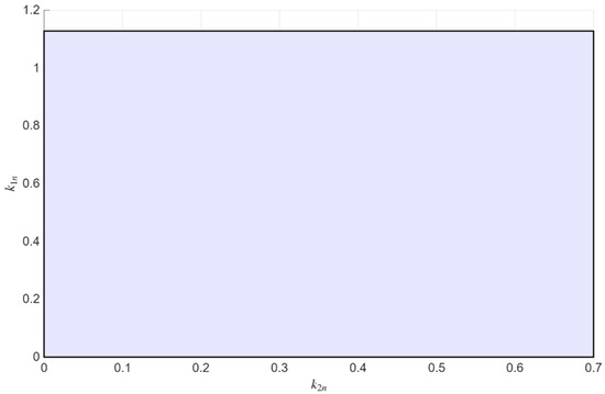
Figure 8.
The performance region of the angular stabilization system on the plane at .
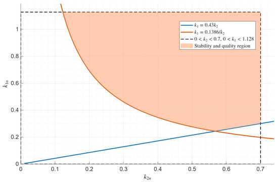
Figure 9.
The stability and performance region of the angular stabilization system on the plane at .
The results of calculating the stability and performance indices of the angular stabilization system at engine thrust are presented in Table 3. As follows from Table 3, both the sufficient stability conditions (11) and the sufficient performance conditions (38) are satisfied.

Table 3.
The results for the stability and performance indices of the angular stabilization system at .
The results of numerical simulation of the angular stabilization system transient process for the specified control law parameters are shown in Figure 10. The transient time in non-dimensional time is s. Comparing the transient process results for the performance regions (13) and (38) shows that, in the latter case with , the transient time decreases by a factor of 1.06. Instead of four real roots of the normalized characteristic Equation (18), there are two real roots and one complex–conjugate pair; however, the transient process shape is practically indistinguishable from an aperiodic response. This can be explained by the fact that the real parts of the complex roots of (18) are an order of magnitude larger than the real root closest to the imaginary axis, so the oscillatory component of the transient process is very small. Consequently, the transient time in non-dimensional time decreases only slightly. A comparison of the stability and performance regions for these two cases shows that for , the stability region (33) is wider than the stability region (40) at , whereas the performance region (43) is wider at than the performance region (36) at .
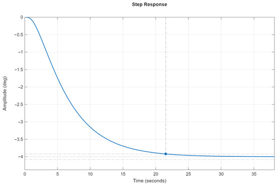
Figure 10.
The transient process of the angular stabilization system in non-dimensional time.
Assume that, according to the angular stabilization system design requirements, its speed must be increased by a factor of 10; that is, the transient time in absolute time must not exceed s. The time-scale factor according to (21) should be . The control law parameters for the transient process in absolute time are determined from (22):
Accordingly, the characteristic Equation (20), taking (44) into account, becomes:
Figure 11 shows the transient process of the angular stabilization system in absolute time corresponding to the characteristic Equation (45). Comparing the transient plots in Figure 10 and Figure 11 shows that the transient process shape remains unchanged, while the transient time decreases by a factor of 10; i.e., the speed increases tenfold.
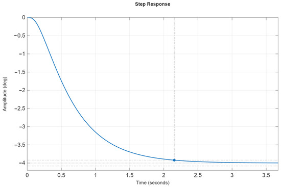
Figure 11.
The transient process of the angular stabilization system in absolute time.
8.4. Achieving the Required Transient Process Shape and Transient Time via the Extended Decomposition Method
We apply the extended decomposition method from Section 6 to synthesize the angular stabilization system control law parameters, setting them according to inequalities (32) for the normalized characteristic Equation (18): . The corresponding coefficients of the normalized characteristic Equation (18) are given by (35): Table 4 presents the results of computing the stability and performance indices of the angular stabilization system at engine thrust and various values of the time scale . As follows from Table 4, the sufficient stability conditions (11) hold for all , while the sufficient performance conditions (13) are satisfied at ; for other values of , only the performance condition involving is not met. Moreover, comparing the stability indices and from Table 4 with the sufficient stability conditions (9) shows that these conditions are fulfilled with a large margin. In addition, despite the fact that for the sufficient performance conditions (13) are not fully satisfied, the transient process shape is practically indistinguishable from an aperiodic response. This can be explained by the real parts of the complex roots of the characteristic Equation (20) being an order of magnitude larger than the real root closest to the imaginary axis, so the oscillatory component of the transient process is very small.

Table 4.
Results for the stability and performance indices of the angular stabilization system .
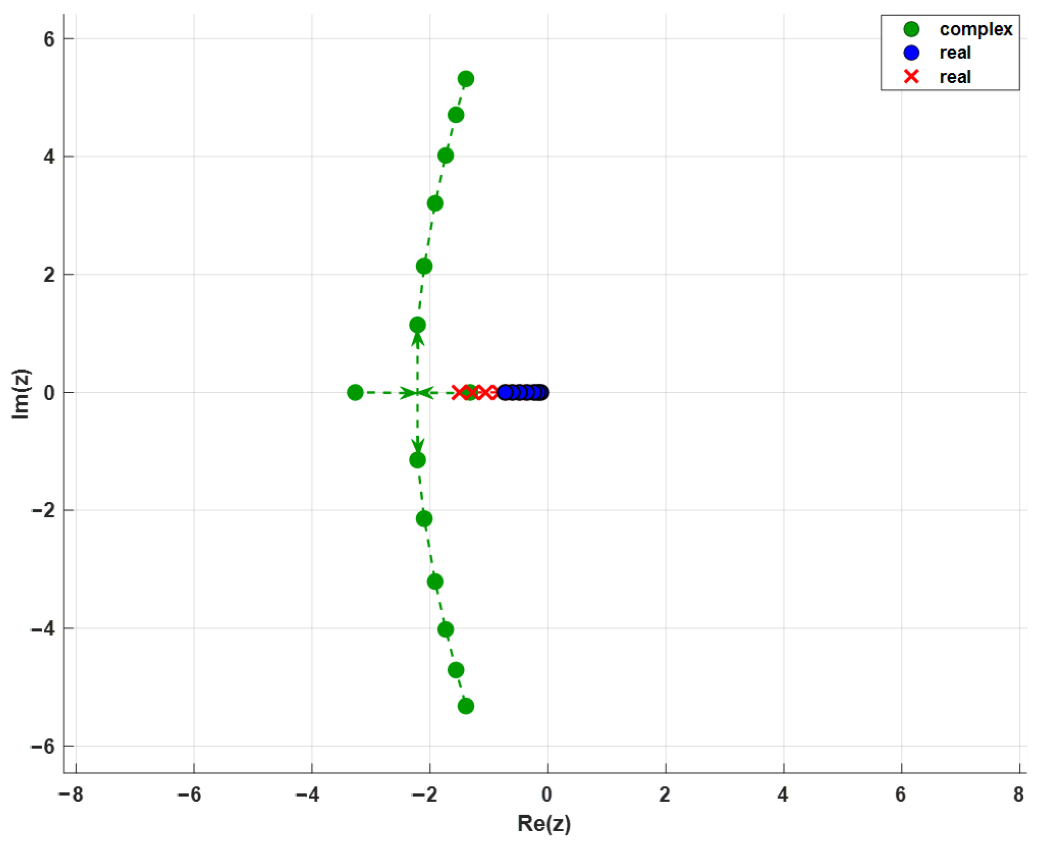
Figure 12 shows the root locus of the characteristic Equation (20) for various values of the time scale (the angular stabilization system speed), demonstrating that as increases, two real roots far from the imaginary axis move toward each other and form a complex–conjugate pair.
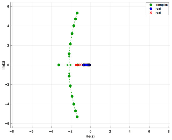
Figure 12.
The root loci of the characteristic Equation (20) for varying .
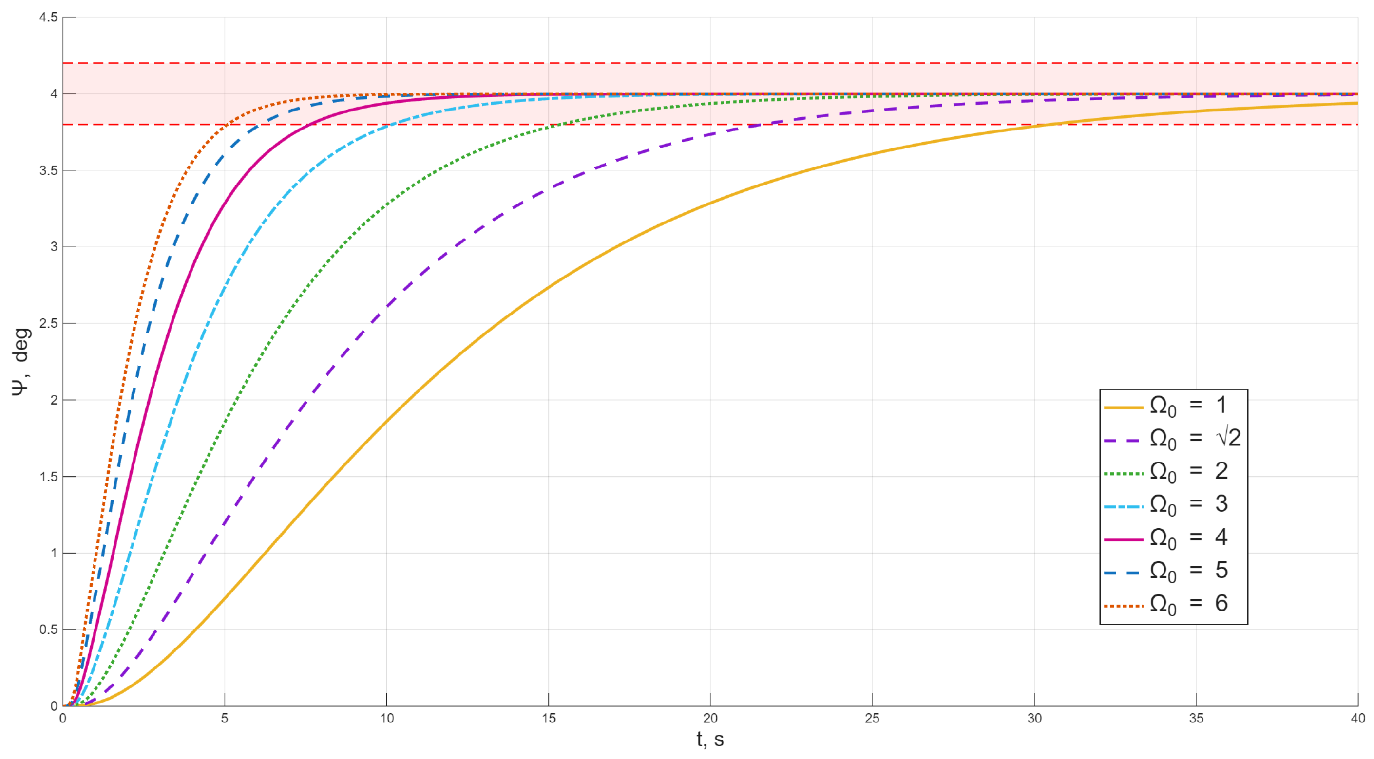
The transient process plots of the angular stabilization system for various values of the time scale are shown in Figure 13. As these plots indicate, with increasing (higher system speed), the transient time decreases in an inverse proportional relationship.
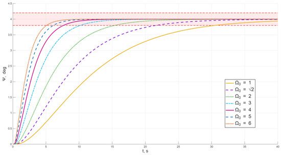
Figure 13.
Transient process plots of the angular stabilization system for various values of .
9. Conclusions
The stability and performance indices of the rocket’s angular stabilization system used in this study—being expressed through the coefficients of its characteristic equation—enable broad use of the coefficient-based approach for both analysis and design of control systems. These capabilities stem from the fact that the coefficient-based approach can equally serve as the foundation for a coefficient-based analysis method and for a coefficient-based design method.
Applying sufficient conditions for stability and performance substantially reduces the complexity of describing the boundaries of the stability and performance regions, allowing these conditions to be written as algebraic systems of inequalities in the physical parameters of the plant and in the control law parameters. The symmetric appearance of these parameters in the inequalities makes them equally suitable for solving analysis problems (when the control law parameters are known) and design problems (when the plant parameters are known).
The proposed decomposition method and its extension integrate well with the developed coefficient-based design method for the rocket angular stabilization system, which introduces stability and performance indices in terms of the required transient process shape and required transient time. The method yields a finite algorithm for determining the control law parameters from the specified stability and performance indices—treating the transient process shape and the system speed as the target indices.
The obtained results for the developed coefficient-based design method show that employing sufficient conditions for stability and performance provides substantial guaranteed margins in practical design. In this regard, the coefficient-based design method can be highly effective for generating initial guesses of control law parameters in optimal synthesis methods and for localizing search regions in machine learning.
A simple and effective way to maintain constant stability and performance indices when designing control systems with controllable engine thrust is to use adaptive control, in which the control law parameters vary with the throttle coefficient of engine thrust.
In future work, the coefficient-based design method can be extended in two directions: (i) development of an extended PID controller with an additional fourth parameter; (ii) development of an AI algorithm for efficiently searching optimal PID parameters, leveraging the proposed decomposition method to reduce by one the dimensionality of the control law parameter search space and thereby decrease computational cost.
Author Contributions
Conceptualization, M.M.; methodology, M.M.; software, A.A. and Y.O.; validation, N.Z., Y.O., M.K., and A.A.; formal analysis, N.Z.; investigation, A.A., M.K., and Y.O.; resources, N.Z.; data curation, M.M.; writing—original draft preparation, A.A. and Y.O.; writing—review and editing, M.M.; visualization, A.A., Y.O., and M.K.; supervision, M.M.; project administration, M.M.; funding acquisition, A.A. All authors have read and agreed to the published version of the manuscript.
Funding
This research has been funded by the Science Committee of the Ministry of Science and Higher Education of the Republic of Kazakhstan (Grant No. AP25794031).
Data Availability Statement
The original contributions presented in the study are included in the article; further inquiries can be directed to the corresponding author.
Conflicts of Interest
The authors declare no conflicts of interest.
References
- Chen, F.; Xue, W.; Tang, Y.; Wang, T. A Comparative Research of Control System Design Based on H∞ and ALQR for the Liquid Rocket Engine of Variable Thrust. Int. J. Aerosp. Eng. 2023, 2023, 2155528. [Google Scholar] [CrossRef]
- Chen, H.; Zhang, Z.; Wang, H. Robust H∞ state-feedback control for linear systems. Proc. R. Soc. A Math. Phys. Eng. Sci. 2017, 473, 1–15. [Google Scholar] [CrossRef]
- Chih, C.-H.; Li, Y.-R.; Peng, C.-C. Dynamics Modeling and Nonlinear Attitude Controller Design for a Rocket-Type Unmanned Aerial Vehicle. ISA Trans. 2024, 152, 15–27. [Google Scholar] [CrossRef] [PubMed]
- Sopegno, L.; Livreri, P.; Stefanovic, M.; Valavanis, K.P. Thrust Vector Controller Comparison for a Finless Rocket. Machines 2023, 11, 394. [Google Scholar] [CrossRef]
- Manoj, N.M.; Sharma, K.K.; Prajeesh, P.; Sreeja, S. Design of LQR Controller for a Flexible Launch Vehicle Using Modified Weighting Matrices. In Proceedings of the IEEE 5th International Conference on Advances in Electronics, Computers and Communications (ICAECC), Bengaluru, India, 7–8 September 2023. [Google Scholar]
- Li, Y.; Zhang, Y.; Liu, X.; Zhang, J. Control System Design for Guided Rocket Base on Adaptive Sliding Mode Control. In Proceedings of the 2020 IEEE International Conference on Information Technology, Big Data and Artificial Intelligence (ICIBA), Chongqing, China, 6–8 November 2020; pp. 1462–1465. [Google Scholar] [CrossRef]
- Dias, M. Control of the Atmospheric Flight Phase of Small Rocket Launchers. Available online: https://resolver.tudelft.nl/uuid:ba049844-4e76-40f6-9e9b-bb517852270f (accessed on 31 October 2025).
- Santos, P.d.; Oliveira, P. Pitch Plane Trajectory Tracking Control for Sounding Rockets via Adaptive Feedback Linearization. arXiv 2025, arXiv:2501.05285. [Google Scholar] [CrossRef]
- Chen, X.; Liu, Y.; Wang, Y. Research on Variable Structure and Adaptive Control for Strap-on Rocket. J. Harbin Inst. Technol. 2017, 24, 87–96. [Google Scholar] [CrossRef]
- Trotta, D.; Zavoli, A.; Matteis, G.D.; Neri, A. Opportunities and Limitations of Adaptive Augmented Control for Launch Vehicle Attitude Control in Atmospheric Flight. Adv. Astronaut. Sci. 2020, 171, 4043–4062. [Google Scholar]
- Sakaoka, E. Attitude Control of Space Launch Vehicles by Using Model Predictive Control. Trans. Soc. Instrum. Control Eng. 2022, 58, 168–178. [Google Scholar] [CrossRef]
- Linsen, R.; Listov, P.; Lajarte, A.D.; Schwan, R.; Jones, C.N. Optimal Thrust Vector Control of an Electric Small-Scale Rocket Prototype. In Proceedings of the 2022 International Conference on Robotics and Automation (ICRA), Philadelphia, PA, USA, 23–27 May 2022; pp. 1996–2002. [Google Scholar] [CrossRef]
- Huang, Z.-R.; Wu, Y.-J.; Zuo, J.-X.; Cheng, L. Backstepping Sliding Mode Control for Missile Attitude System. In Proceedings of the 2018 IEEE CSAA Guidance, Navigation and Control Conference (CGNCC), Xiamen, China, 10–12 August 2018; pp. 1–6. [Google Scholar] [CrossRef]
- Urbina-Brito, N.; Guerrero-Sánchez, M.-E.; Hernández-González, O.; López-Estrada, F.-R.; Valencia-Palomo, G.; Hoyo-Montaño, J.A. A Predictive Control Strategy for Aerial Payload Transportation with an Unmanned Aerial Vehicle. Mathematics 2021, 9, 1822. [Google Scholar] [CrossRef]
- Cavanini, L.; Ippoliti, G.; Camacho, E.F. Model Predictive Control for a Linear Parameter Varying Model of an UAV. J. Intell. Robot. Syst. 2021, 101, 57. [Google Scholar] [CrossRef]
- Petrov, B.N.; Sokolov, N.I.; Lipatov, A.V.; Petrov, B.N. Automatic Control Systems for Objects with Variable Parameters: Engineering Methods of Analysis and Synthesis; Mechanical Engineering: Moscow, Russia, 1986; 256p. (In Russian) [Google Scholar]
- Moldabekov, M.; Aden, A.; Orazaly, Y.; Zhumabekova, N. Optimal Synthesis of a Satellite Attitude Control System under Constraints on Control Torques and Velocities of Reaction Wheels. Mathematics 2024, 12, 2569. [Google Scholar] [CrossRef]
- Besekersky, V.A.; Popov, E.P. Teoriya Sistem Avtomaticheskogo Upravleniya, 4th ed.; Profession: St. Petersburg, Russia, 2007; p. 752. ISBN 5-93913-035-6. (In Russian) [Google Scholar]
- Moldabekov, M.M.; Orazaly, Y.Y.; Aden, A.Y. Construction of the Stability Region of the Rocket Angular Stabilization System by the Coefficient Method. In Advances in Asian Mechanism and Machine Science, Proceedings of the 7th IFToMM Asian Mechanisms and Machine Science Conference (Asian MMS), Almaty, Kazakhstan, 28–30 August 2024; Springer: Almaty, Kazakhstan, 2024; pp. 414–421. [Google Scholar] [CrossRef]
- Moldabekov, M.M.; Aden, A.Y.; Orazaly, Y.Y. Construction of the Region with the Given Control Quality Indicators of the Rocket Angular Stabilization System by the Coefficient Method. In Advances in Asian Mechanism and Machine Science, Proceedings of the 7th IFToMM Asian Mechanisms and Machine Science Conference (Asian MMS), Almaty, Kazakhstan, 28–30 August 2024; Springer: Almaty, Kazakhstan, 2024; pp. 437–444. [Google Scholar] [CrossRef]
Disclaimer/Publisher’s Note: The statements, opinions and data contained in all publications are solely those of the individual author(s) and contributor(s) and not of MDPI and/or the editor(s). MDPI and/or the editor(s) disclaim responsibility for any injury to people or property resulting from any ideas, methods, instructions or products referred to in the content. |
© 2025 by the authors. Licensee MDPI, Basel, Switzerland. This article is an open access article distributed under the terms and conditions of the Creative Commons Attribution (CC BY) license (https://creativecommons.org/licenses/by/4.0/).


