Article

Transient Waves in Linear Dispersive Media with Dissipation: An Approach Based on the Steepest Descent Path

by
Francesco Mainardi
1,
Andrea Mentrelli
2,3,* and
Juan Luis González-Santander
4,*
1
Department of Physics and Astronomy, University of Bologna, Via Irnerio 46, 40126 Bologna, Italy
2
Department of Mathematics, and AM2, University of Bologna, Via Saragozza 8, 40123 Bologna, Italy
3
Istituto Nazionale di Fisica Nucleare (I.N.F.N.), Sezione di Bologna, I.S. FLAG, Viale Berti Pichat 6/2, 40127 Bologna, Italy
4
Department of Mathematics, University of Oviedo, C/Leopoldo Calvo Sotelo 18, 33007 Oviedo, Spain
*
Authors to whom correspondence should be addressed.
Mathematics 2025, 13(21), 3418; https://doi.org/10.3390/math13213418
Submission received: 22 September 2025 / Revised: 13 October 2025 / Accepted: 17 October 2025 / Published: 27 October 2025
(This article belongs to the Section C1: Difference and Differential Equations)

Abstract

In the study of linear dispersive media, it is of primary interest to gain knowledge of the impulse response of the material. The standard approach to compute the response involves a Laplace transform inversion, i.e., the solution of a Bromwich integral, which can be a notoriously troublesome problem. In this paper we propose a novel approach to the calculation of the impulse response, based on the well-assessed method of the steepest descent path, which results in the replacement of the Bromwich integral with a real line integral along the steepest descent path. In this exploratory investigation, the method is explained and applied to the case study of the Klein–Gordon equation with dissipation, for which analytical solutions of the Bromwich integral are available, so as to compare the numerical solutions obtained by the newly proposed method to exact ones. Since the newly proposed method, at its core, consists of replacing a Laplace transform inverse with a potentially much less demanding real line integral, the method presented here could be of general interest in the study of linear dispersive waves in the presence of dissipation, as well as in other fields in which Laplace transform inversion comes into play.

1. Introduction

For uniaxial waves in an initially quiescent semi-infinite medium ( x 0 ), the response r x , t of the medium to a pulse r 0 t = r 0 , t is [1]:
r x , t = 1 2 π i B r r ˜ 0 s exp s t n s x / c d s ,
where s is the Laplace parameter, r ˜ 0 s is the Laplace transform of the pulse r 0 t , n s is the Laplace transform of the medium refraction index, B r is the Bromwich path, and c is the wave front velocity. When r 0 t = δ t , its Laplace transform reads r ˜ 0 s = 1 so the corresponding response (the propagator or the impulse response) is obtained inverting the Laplace transform
r ˜ δ x , s = exp s n s x / c .
Then, the solution corresponding to the generic r 0 t is obtained by convolution
r x , t = r 0 t r δ x , t = 0 t r 0 t t r δ x , t d t .
Another relevant initial response is that with Laplace transform
r ˜ n x , s = exp s n s x / c s n s ,
so r δ x , t can be obtained from r n x , t by partial derivative with respect to x. Of course, the corresponding Laplace transforms exhibit the same singular points, i.e., those of n s .
We have two ways to represent the solution of Equation (1); that is, versus x (at fixed time t), and versus t (at fixed position x). In the first case, we have 0 x c t , while in the second case, we have t x / c 0 . Correspondingly, we introduce the parameters
μ = x c t 0 μ 1 , θ = c t x 1 θ .
In order to decrease the computational difficulties for the Laplace inversion, we propose to deform the original path of integration (the Bromwich path) in Equation (1) into another equivalent to it (unless possible contributions of singularities) that is expected to be more convenient, i.e., the steepest descent path through the saddle points of the complex function
F μ s = s 1 μ n s , F θ s = s 1 n s / θ ,
according to our choice of representation in Equation (5). We refer to the reader to [2,3] for a detailed explanation of the steepest descent method and its applications.

2. The Klein–Gordon Equation with Dissipation

A model equation for uniaxial waves in dispersive media with dissipation is the Klein–Gordon equation with an additional term that takes into account of attenuation due to dissipation. We refer to this equation as the Klein–Gordon with dissipation, i.e., KGD equation [4]
r t t + a r t + b r c 2 r x x = 0 ,
where r = r x , t is the response variable, c 2 denotes the square of the wave-front velocity, and a , b are non-negative constants. If b = 0 the equation reduces to the so-called telegraph equation, whereas if a = 0 we recover the classical Klein–Gordon equation without dissipation. The space-time coordinates are taken in the quadrant x , t 0 . Also, we keep the usual boundary and initial conditions
r 0 , t = r 0 t , lim x r x , t = 0 ,
r x , 0 = r t x , 0 = 0 .
The complex index of refraction associated to the KGD equation reads as
n s = s 2 + a s + b s = s + a / 2 2 + Δ s , Δ = b 2 a 2 4 .
As a consequence, we write the following solutions in the Laplace domain:
r ˜ δ x , s = exp x c s + a / 2 2 + Δ ,
r ˜ n x , s = exp x c s + a / 2 2 + Δ s + a / 2 2 + Δ .
For the impulse response, we get (see [5], Equations (126) and (127), p. 213):
  • If Δ > 0 ,
    r δ x , t = exp a x 2 c δ t x c x c Δ exp a t 2 J 1 Δ t 2 x 2 c 2 t 2 x 2 c 2 Θ t x c ,
  • If Δ < 0 ,
    r δ x , t = exp a x 2 c δ t x c + x c Δ exp a t 2 I 1 Δ t 2 x 2 c 2 t 2 x 2 c 2 Θ t x c ,
    where Θ t denotes the Heaviside theta function, and J 1 t and I 1 t are the Bessel and modified Bessel function of first order, respectively ([6], Chaps. 49&52).
For the other response, we get (see [5], Equations (124) and (125), p. 213)
  • If Δ > 0 ,
    r n x , t = exp a t 2 J 0 Δ t 2 x 2 c 2 t 2 x 2 c 2 Θ t x c ,
  • If Δ < 0 ,
    r n x , t = exp a t 2 I 0 Δ t 2 x 2 c 2 t 2 x 2 c 2 Θ t x c ,
    where now J 0 t and I 0 t are the Bessel and modified Bessel function of zeroth order, respectively. In particular case of the telegraph equation, i.e., b = 0 , we get Δ = a 4 / 4 < 0 , and the corresponding response was found by Lee–Kanter for the Maxwell model of linear viscoelasticity [7].
We wish to approximate the solutions r δ x , t and r n x , t , computing the inverse Laplace transforms given in Equations (11) and (12), by means of the steepest descent method, and then compare the results to the exacts solution provided in Equations (14) and (15). This method consists in replacing the Bromwich path with the so-called steepest descent path (SDP), that requires finding the saddle points of the F μ function defined in Equation (6). For the particular case of the KGD equation, insert Equation (10) into Equation (6) to obtain
F μ s = s μ s + a / 2 2 + Δ .
We recall that the required steepest descent path (see [2,3]) is the path through saddle points of F μ along which the real part of F μ attains its maximum value so that the imaginary part of F μ is constant. We note that the steepest descent path, denoted in the following as γ μ , depends on the parameter μ .
In order to proceed with the determination of the saddle points of F μ , which are the solution of F μ s = 0 , and the steepest descent path γ μ , it is convenient to discuss separately the cases with Δ < 0 and Δ > 0 . Indeed, we deal at first with the easiest case Δ < 0 because the corresponding γ μ turns out to be a closed curve, while for Δ > 0 the corresponding γ μ turns out to be a couple of open curves symmetric with respect to the negative real axis.
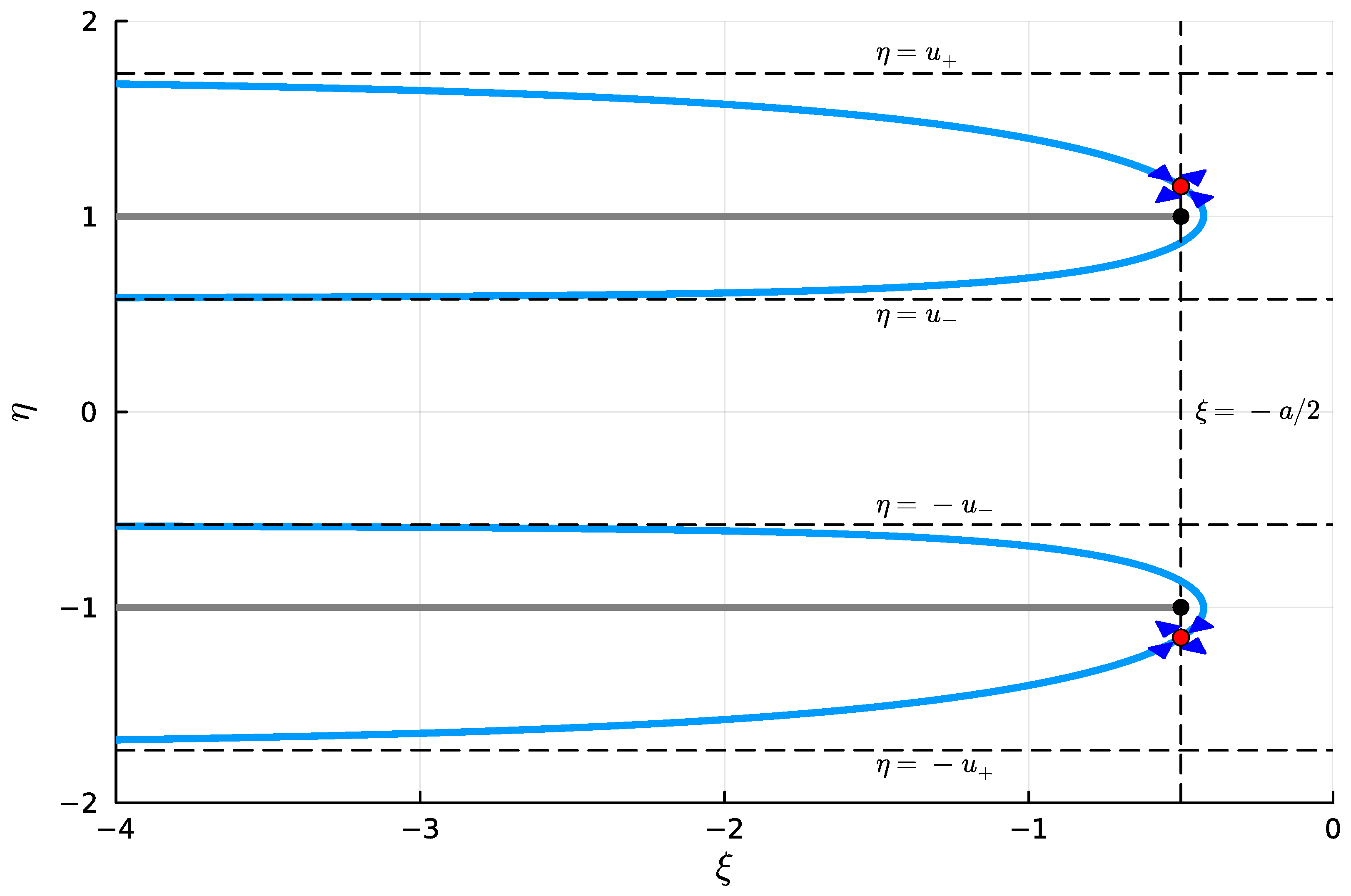
In the figures of the SDP, the saddle points are characterized by arrows that show the direction of ascent along the lines of steepest descent, according the convection used by Brilluoin.

3. The Determination of the Steepest Descent Path

3.1. Case Δ < 0

If Δ < 0 , the saddle points of the function F μ s are the following:
p 1 = a 2 Δ 1 μ 2 , p 2 = a 2 + Δ 1 μ 2 ,
which are both real. The values of F μ at the saddle points p 1 and p 2 are respectively ϕ 1 = φ 1 + ω 1 i and ϕ 2 = φ 2 + ω 2 i with
φ 1 = a 2 + 1 μ 2 Δ 1 μ 2 ,
φ 2 = a 2 1 + μ 2 Δ 1 μ 2 ,
ω 1 = ω 2 = 0 .
Since ϕ 1 and ϕ 2 are both real (i.e., the imaginary part of F μ is zero in the two saddle points), the steepest descent path is in this case a curve in the complex plane passing through the two saddle points p 1 and p 2 . In passing, we note that the branch points (namely, the points for which the argument of the square root vanishes) are the following:
b 1 = a 2 Δ , b 2 = a 2 + Δ .
The branch points, as the saddle points, are on the real axis, and
p 1 b 1 < a 2 < b 2 p 2 ,
where the equal signs hold for the limit value μ = 0 .
On the steepest descent path though the saddle points p 1 , p 2 , the imaginary part of F μ is constant (and equal to ω 1 = ω 2 = 0 ), therefore the steepest descent path is found as follows:
Im F μ = Im s μ s + a / 2 2 + Δ = 0 .
Setting s = ξ + η i , and s + a / 2 2 + Δ = A + B i , with ξ , η , A , B R , we have
η μ B = 0 ,
ξ + a / 2 2 + Δ = A 2 B 2 ,
ξ + a 2 η = A B ,
from which we readily find
ξ + a / 2 2 α 2 + η 2 β 2 = 1 ,
with
α = Δ 1 μ 2 , β = μ α = μ Δ 1 μ 2 .
The steepest descent path γ μ turns out to be a one-parameter family of ellipses with semi-axes α and β , see Figure 1.

3.2. Case Δ > 0

In this case, the saddle points of the F μ function are the following:
p 1 = a 2 i Δ 1 μ 2 , p 2 = a 2 + i Δ 1 μ 2 ,
which are complex conjugates. The values of F μ at the saddle points p 1 and p 2 are, respectively, ϕ 1 = φ 1 + ω 1 i and ϕ 2 = φ 2 + ω 2 i with
φ 1 = φ 2 = a 2 ,
ω 1 = + Δ 1 μ 2 ,
ω 2 = Δ 1 μ 2 .
The branch points (which are complex conjugates) are the following:
b 1 = a 2 i Δ , b 2 = a 2 + i Δ .
We note that the saddle points, as well as the branch points, lie on the line ξ = a / 2 parallel to the imaginary axis, and their imaginary parts are such that
Im p 1 Im b 1 < 0 < Im b 2 Im p 2 ,
where the equal signs hold for the limit value μ = 0 .
In contrast to the case with Δ < 0 , the steepest descent path γ μ is now made of two branches: a branch through the saddle point p 1 , denoted as γ μ , 1 , and a branch through the saddle point p 2 , denoted as γ μ , 2 .
Along the branch of the steepest descent path though the saddle point p k ( k = 1 , 2 ), the imaginary part of F μ is constant and equal to ω k , i.e.,
Im F μ = Im s μ s + a / 2 2 + Δ = ω k .
Proceeding as in the case with Δ < 0 , we find
η μ B = ω k ,
ξ + a / 2 2 η 2 + Δ = A 2 B 2 ,
ξ + a 2 η = A B ,
from which we find for k = 1 , 2
ξ + a 2 2 = η ω k μ 2 η ω k 2 + μ 2 Δ η 2 μ 2 η 2 η ω k 2 ,
which defines the branch γ μ , 1 of the steepest descent path through the saddle point p 1 (for k = 1 ), and the branch γ μ , 2 through the saddle point p 2 (for k = 2 ). The steepest descent path is defined as γ μ = γ μ , 1 γ μ , 2 . An analysis of Equation (40) reveals that the two branches of the path γ μ , i.e., γ μ , 1 and γ μ , 2 , are symmetric with respect to the real axis, see Figure 2.
An inspection of the properties of γ μ , k shows that each branch of γ μ , k has two horizontal asymptotes given by
η = u ± 1 ± μ 1 μ Δ ,
where, taking as parameter u = η , we have the parametrization
γ μ , k u = g k u + i u , u < ( 1 ) k u < u + ,
where
g k u = a 2 ± u ω k μ u ω k 2 + μ 2 Δ u 2 μ 2 u 2 u ω k 2 .

4. Numerical Evaluation of r δ x , t

4.1. Case Δ < 0

In this case, γ μ is a closed curve which can be easily parameterized as follows:
γ μ u = a 2 + α cos u + i β sin u , 0 u < 2 π ,
from which
γ μ u = α sin u + i β cos u .
Letting
f δ x , t ; s = 1 2 π i exp s t x c s + a 2 2 + Δ ,
with the above parametrization, the integral along γ μ turns into a real line integral (of the complex f δ function) as follows:
r δ x , t = γ μ f δ x , t ; s d s = 0 2 π f δ x , t ; γ μ u γ μ u d u .
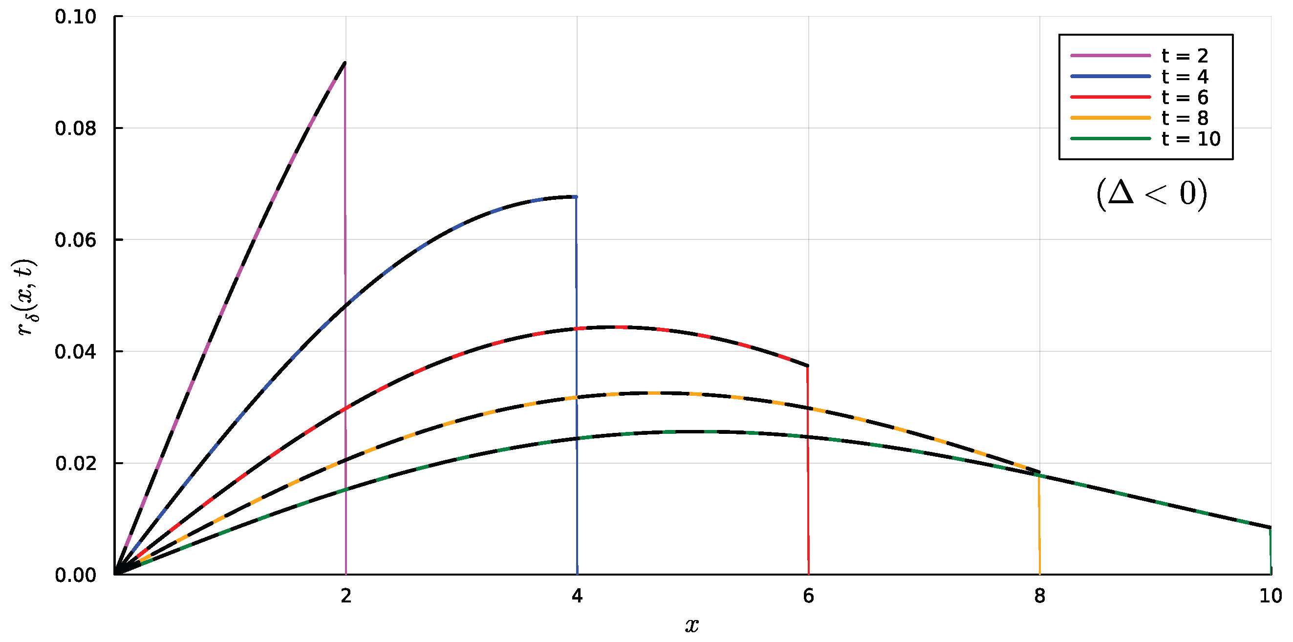
The resulting integral can be numerically evaluated by means of a standard numerical method, such as the adaptive Gauss–Kronrod quadrature. A comparative between numerical and exact results is shown in Figure 3, where the solution r δ x , t is plotted as a function of x for several values of t.

4.2. Case Δ > 0

Following the procedure outlined for the case Δ < 0 , and replacing the Bromwich path by the descendent γ μ , we have
r δ x , t = γ μ , 1 γ μ , 2 f δ x , t ; s d s = I δ , 1 + I δ , 2 ,
where k = 1 , 2
I δ , k = γ μ , k f δ x , t ; s d s .
Deploying the parametrization discussed above, we have
I δ , k = 1 k 1 k u 1 k u + f δ x , t ; γ μ , k u γ μ , k u d u ,
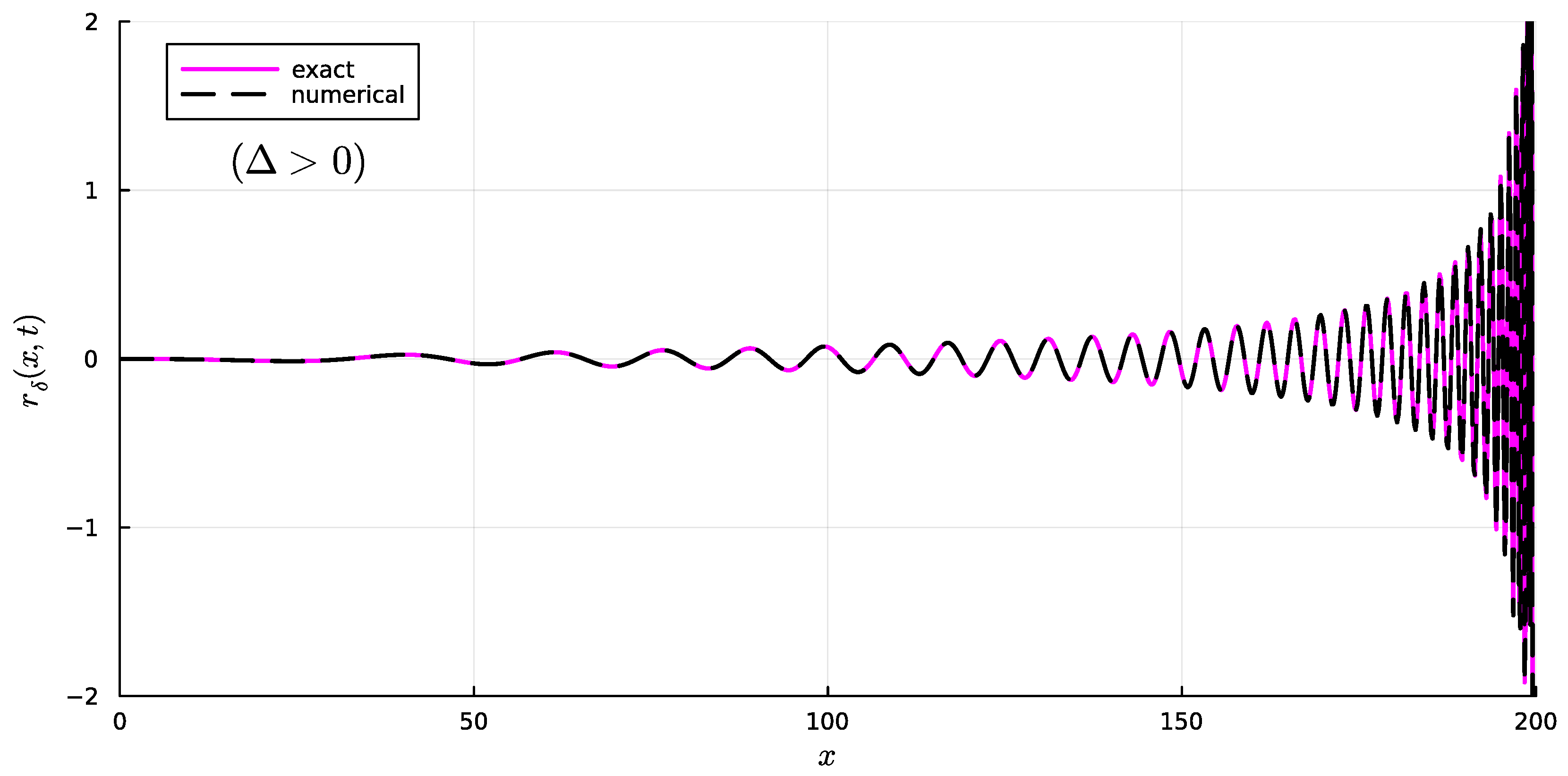
where γ μ , k is given in (41) and (42), and γ μ , k u = g k u + i . As for the case with Δ < 0 , the Bromwich integral is therefore replaced by real line integrals, which can be evaluated by means of standard algorithms. In Figure 4 and Figure 5, comparisons between numerical and exact results are plotted for two set of parameter values.

4.3. Useful Property of the Integrals for r δ x , t

Since the exact solutions given in Equations (13) and (14) are clearly real, and the solutions given in Equations (47) and (46) are respectively equivalent to them, then Equations (47) and (46) must be real as well. Therefore, we expect that the real line integrals (of the complex function f δ ) emerging from the application of the steepest descent method must be real.
On this regard, we observe that the steepest descent paths are, in both cases with Δ < 0 and Δ > 0 , symmetric with respect to the real axis, see Figure 1 and Figure 2. For instance, for the case Δ < 0 , we can split the integral given in Equation (46) as
r δ x , t = 0 π f δ x , t ; γ μ u γ μ u d u H 1 , δ + π 2 π f δ x , t ; γ μ u γ μ u d u H 2 , δ .
We appreciate that, due to the symmetry properties of the paths and the features of the integrand function f, the integrals H 1 , δ and H 2 , δ are complex conjugates, i.e., H 2 , δ = H ¯ 1 , δ , which allows us to write
r δ x , t = 2 Re H 1 , δ .
This observation is beneficial because it guarantees to obtain a real solution without any spurious imaginary part that could emerge from the numerical approximation of the integrals H 1 and H 2 .
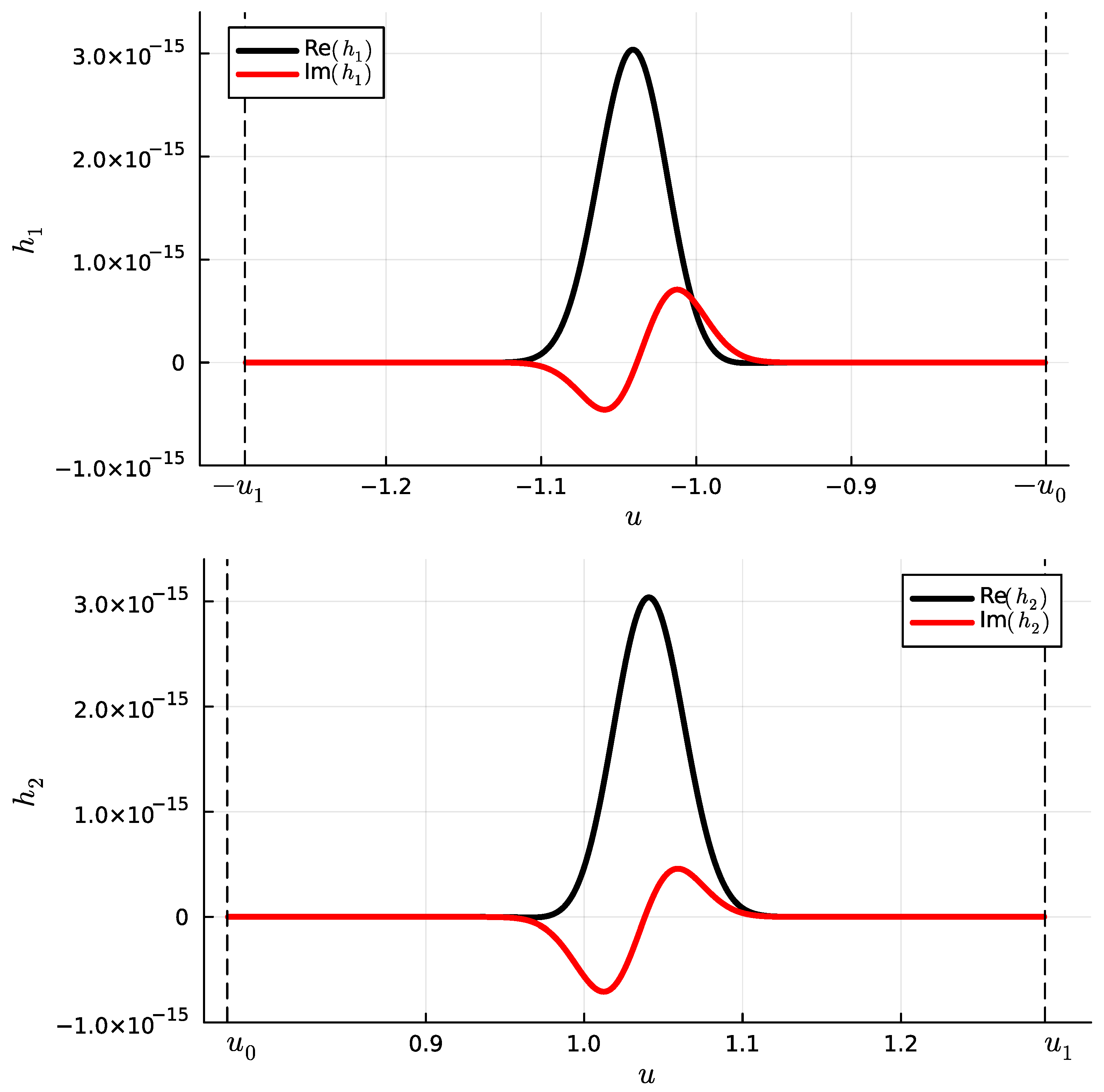
In Figure 6, the integrand functions h k x , t ; u = f δ x , t ; γ μ , k u γ μ , k u appearing in (49) for an exemplary case are plotted

5. Numerical Evaluation of r n x , t

5.1. Case Δ < 0

In this case, the parametrization γ μ is given in (43). Letting
f n x , t ; s = 1 2 π i exp s t x c s + a / 2 2 + Δ s + a / 2 2 + Δ ,
the integral along γ μ turns out to be a real line integral (of the complex function f n ), so that
r n x , t = γ μ f n x , t ; s d s = 0 2 π f n x , t ; γ μ u γ μ u d u .
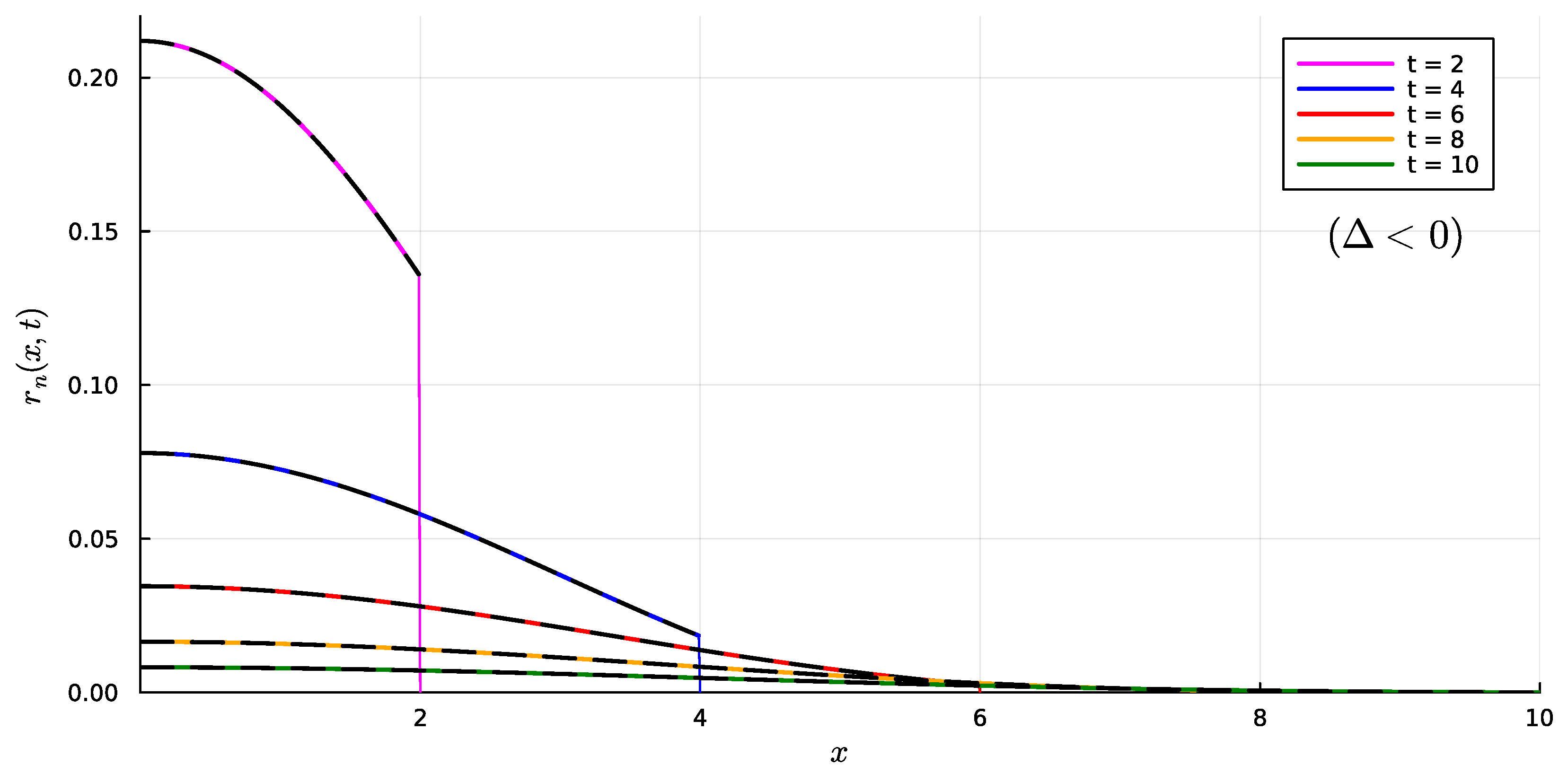
Again, the resulting integral may be numerically evaluated by means of a standard numerical method, such as the adaptive Gauss–Kronrod quadrature. A comparison between numerical and exact results is shown in Figure 7, where the solution r n x , t is plotted as a function of x for several values of t.

5.2. Case Δ > 0

In this case, the parametrization γ μ , k is given in (41). Consequently, we have
r n x , t = γ μ , 1 γ μ , 2 f n x , t ; s d s = I n , 1 + I n , 2 ,
where k = 1 , 2
I n , k = γ μ , k f n x , t ; s d s .
Deploying the parametrization discussed above, we have
I n , k = 1 k 1 k u 1 k u + f n x , t ; γ μ , k u γ μ , k u d u ,
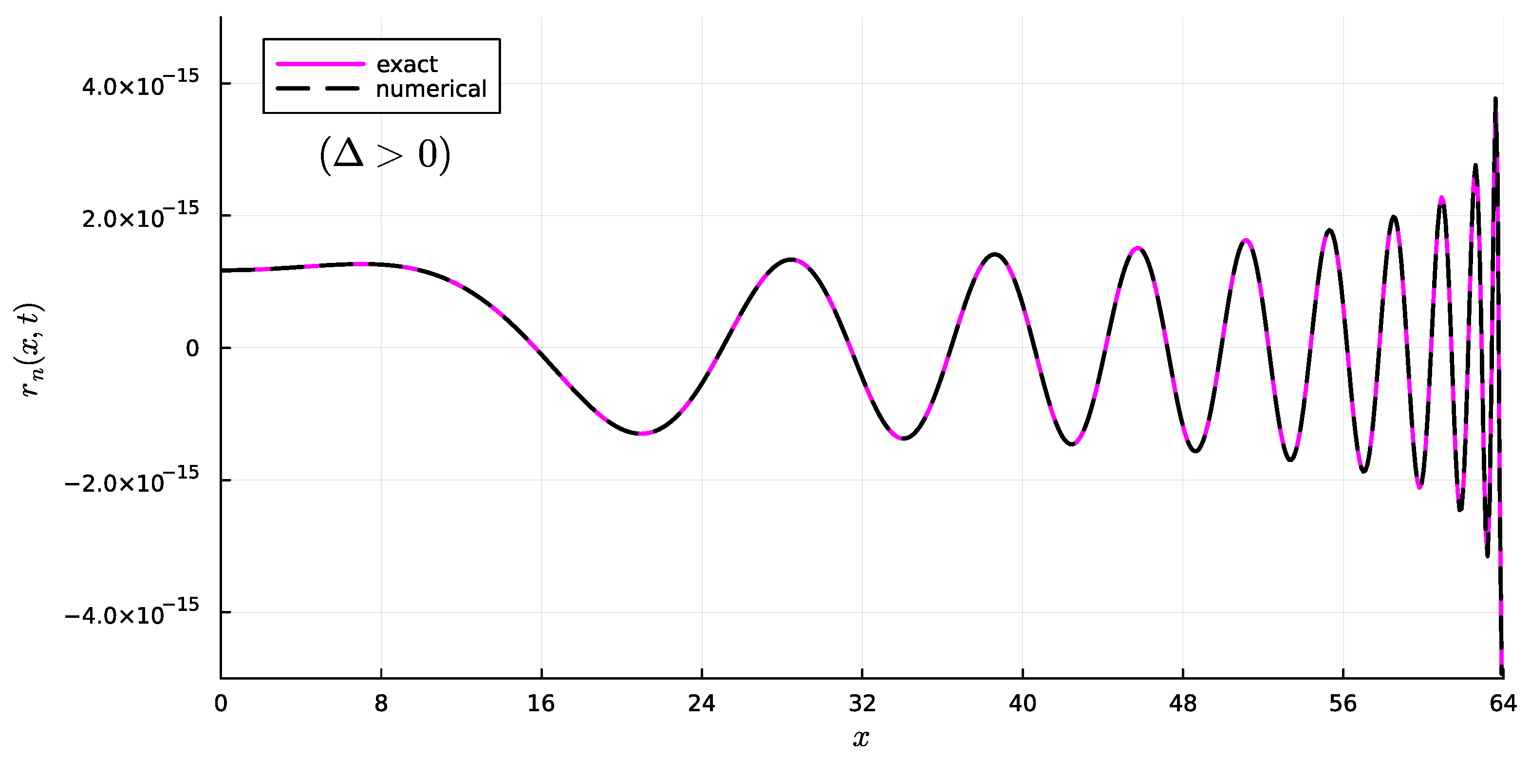
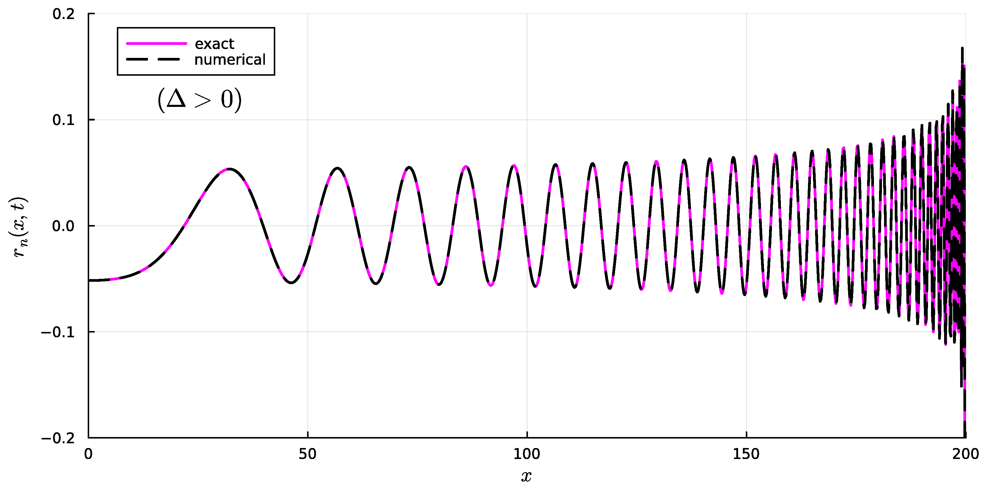
where γ μ , k is given in (41) and (42), and γ μ , k u = g k u + i . As for the case with Δ < 0 , the Bromwich integral is therefore replaced by real line integrals, which can be evaluated by means of standard algorithms. In Figure 8 and Figure 9, comparisons between numerical and exact results are plotted for two set of parameter values.

5.3. Useful Property of the Integrals for r n x , t

Since the exact solutions given in Equations (15) and (16) are clearly real, and the solutions given in Equations (54) and (53) are, respectively, equivalent to them, then Equations (54) and (53) must be real as well. Therefore, we expect that the real line integrals (of the complex function f n ) emerging from the application of the steepest descent method must be real.
Consequently, analogously to the result obtained previously, it turns out that
r n x , t = 2 Re H 1 , n ,
where
H 1 , n : = 0 π f n x , t ; γ μ u γ μ u d u .

6. Conclusions

It is worth stressing that the method discussed here consists in turning the Bromwich integral into a real line integral of a well-behaved function, for the solution of which is well-established (and well-performing) quadrature formulas may be used.
Consequently, unlike the traditional usage of the steepest descent method to calculate the asymptotic behavior of the Bromwich integral nearby the saddle points, here we consider the entire steepest descent path. Therefore, our method does not provide an asymptotic result, but an exact one, neglecting the computational error in the numerical evaluation of the corresponding real line integral.
The possibly hard problem of finding r δ x , t is therefore transferred from the algorithm for the numerical approximation of the Bromwich integral, to the analytical calculation (and parametrization) of the steepest descent path. This is in contrast to the majority of the most popular algorithms available for the inversion of the Laplace transform, which focuses on the numerical solution of the Bromwich integral (or other equivalent integrals in the complex plane), which is a notoriously difficult task. Even the most popular algorithms for the numerical inversion of Laplace transforms (see [8,9,10]) are known to provide, in critical cases, solutions affected by very large errors, which—when the exact solution is not available—can be difficult to spot, potentially leading to unreliable results.

Author Contributions

Conceptualization, F.M.; methodology, F.M., A.M. and J.L.G.-S.; software, A.M.; data curation, F.M., A.M. and J.L.G.-S.; writing—original draft preparation, A.M.; writing—review and editing, F.M., A.M. and J.L.G.-S.; supervision, J.L.G.-S. All authors have read and agreed to the published version of the manuscript.

Funding

The research of F. Mainardi and A. Mentrelli was carried out in the framework of the activities of the Italian National Group of Mathematical Physics [Gruppo Nazionale per la Fisica Matematica (GNFM), Istituto Nazionale di Alta Matematica (INdAM)]. A. Mentrelli is partially funded by the European Union—NextGenerationEU under the National Recovery and Resilience Plan (PNRR)—Mission 4 Education and research, Component 2 From research to business—Investment 1.1 Notice PRIN 2022—DD N. 104 dated 2 February 2022, entitled “The Mathematics and Mechanics of Non-linear Wave Propagation in Solids” (proposal code: 2022P5R22 A; CUP: J53D23002350006), and by the Italian National Institute for Nuclear Physics (INFN), grant FLAG.

Data Availability Statement

Data sharing is not applicable.

Conflicts of Interest

The authors declare no conflicts of interest.

References

  1. Mainardi, F. Fractional Calculus and Waves in Linear Viscoelasticity: An Introduction to Mathematical Models, 2nd ed.; World Scientific: Singapore, 2022; [1st edition 2010]. [Google Scholar]
  2. Brillouin, L. Wave Propagation and Group Velocity; Academic Press: New York, NY, USA, 1960. [Google Scholar]
  3. Mainardi, F.; Vitali, G. Applications of the Method of Steepest Descents in Wave-Propagation Problems. In Asymptotic and Computational Analysis; Wong, R., Ed.; Marcel Dekker Inc.: New York, NY, USA, 1990; pp. 639–651. [Google Scholar]
  4. Mainardi, F. Signal velocity for transient waves in linear dissipative media. Wave Motion 1983, 5, 33–41. [Google Scholar] [CrossRef]
  5. Ghizzetti, A.; Ossicini, A. Trasformate di Laplace e Calcolo Simbolico; Unione Tipografico-Editrice Torinese: Turin, Italy, 1971. [Google Scholar]
  6. Oldham, K.B.; Myland, J.; Spanier, J. An Atlas of Functions: With Equator, the Atlas Function Calculator; Springer: Berlin/Heidelberg, Germany, 2009. [Google Scholar]
  7. Lee, E.; Kanter, I. Wave propagation in finite rods of viscoelastic material. J. Appl. Phys. 1953, 24, 1115–1122. [Google Scholar] [CrossRef]
  8. Talbot, A. The accurate numerical inversion of Laplace transforms. Ima J. Appl. Math. 1979, 23, 97–120. [Google Scholar] [CrossRef]
  9. Weideman, J. Optimizing Talbot’s contours for the inversion of the Laplace transform. Siam J. Numer. Anal. 2006, 44, 2342–2362. [Google Scholar] [CrossRef]
  10. Weideman, J.; Trefethen, L. Parabolic and hyperbolic contours for computing the Bromwich integral. Math. Comput. 2007, 76, 1341–1356. [Google Scholar] [CrossRef]
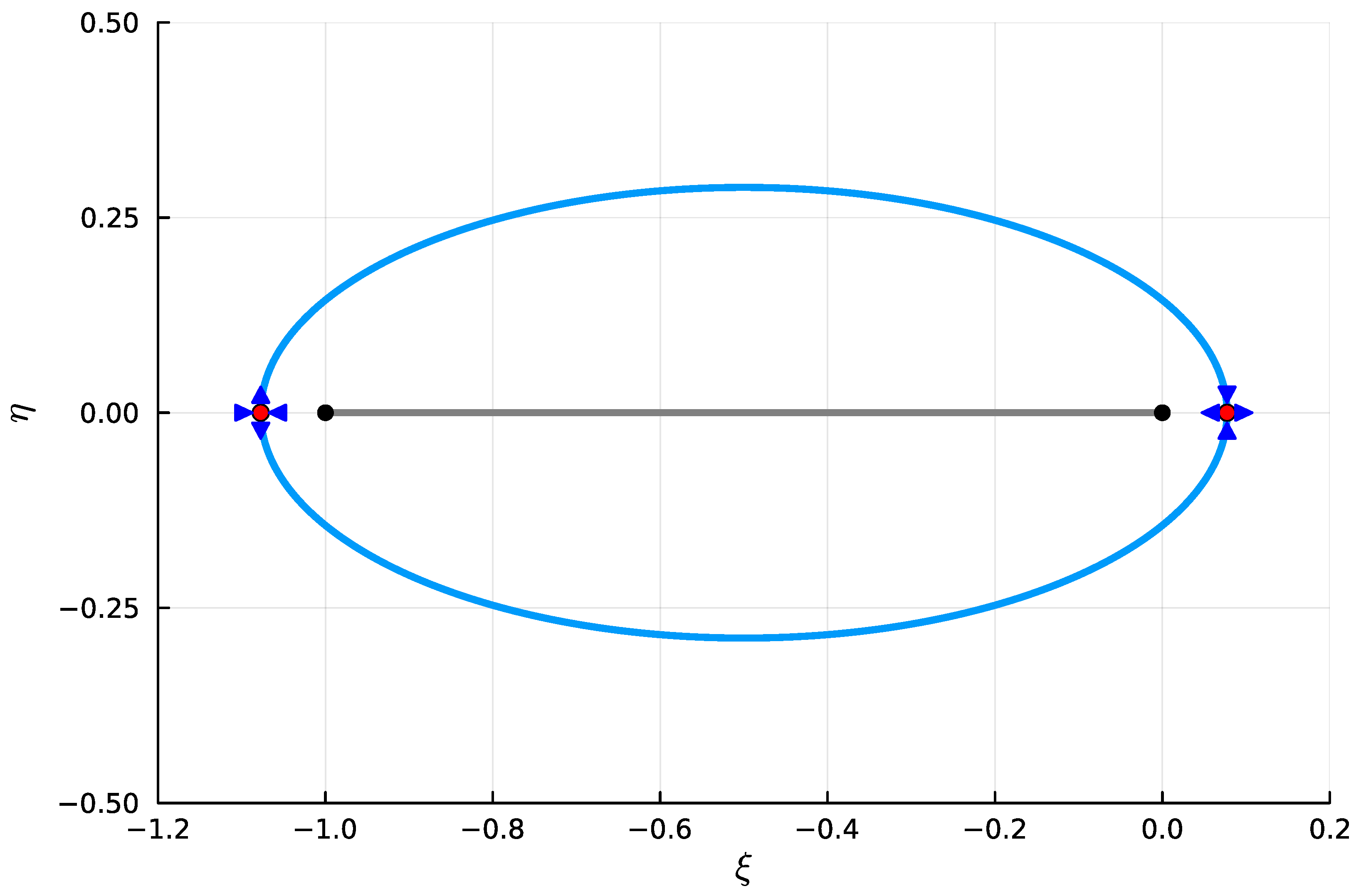
Figure 1. Steepest descent path for the case Δ < 0 (blue curve). The red and black dots represent, respectively, the saddle points and the branch points; the grey line represents the branch cut (values of the parameters: a = 1 , b = 0 , c = 1 , Δ = 1 / 4 ; μ = 1 / 2 ).
Mathematics 13 03418 g001
Figure 2. Steepest descent path for the case Δ > 0 (blue curve). The red and black dots represent, respectively, the saddle points and the branch points; the grey line represents the branch cut (values of the parameters: a = 1 , b = 5 / 4 , c = 1 , Δ = 1 ; μ = 1 / 2 ).
Mathematics 13 03418 g002
Figure 3. Comparison between exact and numerical solutions for the case Δ < 0 , for several values of t (values of the parameters: a = 1 , b = 0 , c = 1 , Δ = 1 / 4 ).
Mathematics 13 03418 g003
Figure 4. Comparison between exact and numerical results for the case with Δ > 0 (values of the parameters: a = 1 , b = 5 / 4 , c = 1 , Δ = 1 , t = 64 ).
Mathematics 13 03418 g004
Figure 5. Comparison between exact and numerical results for the case with Δ > 0 (values of the parameters: a = 10 4 , b = 5 , c = 2 , Δ = 4.9999999975 , t = 100 ).
Mathematics 13 03418 g005
Figure 6. Real and imaginary parts of the functions h k x , t ; u = f δ x , t ; γ μ , k u γ μ , k u ( k = 1 , 2 ) as functions of the variable of integration u (values of the parameters: a = 1 , b = 5 / 4 , c = 1 , Δ = 1 , t = 64 , x = 16 ).
Mathematics 13 03418 g006
Figure 7. Comparison between exact and numerical solutions for the case Δ < 0 , for several values of t (values of the parameters: a = 2 , b = 1 / 2 , c = 1 , Δ = 1 / 2 ).
Mathematics 13 03418 g007
Figure 8. Comparison between exact and numerical results for the case with Δ > 0 (values of the parameters: a = 1 , b = 5 / 4 , c = 1 , Δ = 1 , t = 64 ).
Mathematics 13 03418 g008
Figure 9. Comparison between exact and numerical results for the case with Δ > 0 (values of the parameters: a = 10 4 , b = 5 , c = 2 , Δ = 4.9999999975 , t = 100 ).
Mathematics 13 03418 g009
Disclaimer/Publisher’s Note: The statements, opinions and data contained in all publications are solely those of the individual author(s) and contributor(s) and not of MDPI and/or the editor(s). MDPI and/or the editor(s) disclaim responsibility for any injury to people or property resulting from any ideas, methods, instructions or products referred to in the content.