Abstract
This study investigates the thermoelastic frictional contact and wear behavior during reciprocating sliding of a conductive cylindrical punch on a functionally graded piezoelectric material (FGPM)-coated half-plane. The thermo-electro-elastic properties of the coating vary continuously along the thickness direction according to arbitrary gradient functions, with thermal parameters being temperature-dependence. A theoretical framework for the coupled thermo-electro-elastic frictional contact problem is developed and solved using the finite element method. A sequential coupling approach is employed to integrate thermoelastic frictional contact with piezoelectric effects. Furthermore, wear on the coating surface is modeled using an improved Archard formulation, accounting for its impact on thermal sliding frictional contact characteristics. Numerical simulations examine the influence of wear, cycle number, friction coefficient, gradient index and gradient form on the coupled thermo-electro-elastic response of the FGPM coating structure. The numerical results demonstrate the gradient index and gradient form can effectively mitigate thermo-electrical contact-induced damage and reduce friction and wear in piezoelectric materials.
Keywords:
functionally graded piezoelectric materials; finite element method; coated half-plane; thermal sliding friction; piezoelectric; wear MSC:
74A40; 74S05; 74R99
1. Introduction
Piezoelectric materials are widely employed in engineering structures and advanced technologies due to their excellent mechanical properties and inherent mechano-electrical coupling effects, attracting significant research attention from material scientists, mechanicians and engineers. As applications of piezoelectric materials expand, key components such as piezoelectric motors, actuators and friction dampers [1,2,3,4] often operate under extreme conditions involving combined thermal, electrical and mechanical loads. Most of these applications involve thermo-electro-electrical contact process. The introduction of frictional heat, along with the external thermal, mechanical, and electrical loads, can induce severe thermoelastic contact damage and surface wear, ultimately leading to failure of piezoelectric components and structures. Hence, there is a pressing need to develop effective methods for mitigating thermos-electro-elastic contact damage and wear in piezoelectric materials.
Functionally Graded Materials (FGMs) are characterized by material properties that vary gradually with spatial position. Building on this concept, functionally graded piezoelectric materials (FGPMs) have been developed as a novel class of smart composite that integrate the advantages of both piezoelectricity and gradient functionality. Recent studies on the contact mechanics of FGPMs have demonstrated that using FGPMs as coatings materials can significantly enhance the surface resistance to contact-induced and electrically induced damage a performance unattainable with homogeneous piezoelectric materials.
Scholars have made significant progress in the theoretical, numerical and experimental analysis of contact and thermal contact problems involving FGPMs [5,6,7,8,9,10,11,12,13,14,15,16,17]. For instance, Ke et al. [5,6] employed an exponential model to simulate parameter variations and investigated two-dimensional frictionless/sliding frictional contact of functionally graded piezoelectric half-planes under various punch actions. Using Fourier integral transforms, Singh et al. [8] analyzed the sliding contact behavior of FGPMs. Kargarnovin et al. [9] also adopted an exponential model to study the two-dimensional thermal contact reponse of FGPMs under thermo-electro-mechanical loads. Vasiliev et al. [10] derived fundamental solutions for a transversely isotropic FGPM-coated half-space subjected to point forces and charges. Ma et al. [11,12,13] examined two-dimensional frictionless, sliding frictional contact and frictional thermal contact between a graded magneto-electro-elastic coated half-plane and a rigid conductive and magnetically permeable punch. Liu et al. [14,16] explored the axisymmetric frictionless contact of an FGPM-coated half-space under conductive or insulated cylindrical and spherical punches, and later extended the study to finite frictional contact under an insulated spherical punch [15]. Çömez et al. [7] investigated both continuous and discontinuous planar contact between a functionally graded piezoelectric layer and a homogeneous piezoelectric half-plane, analyzing the influence of layer length, mechanical and electrical loads, and gradient inhomogeneity on contact stress and electric displacement. Finally, Zhou et al. [17] studied thermal frictional sliding contact in an FGPM-coated half-plane under a rigid conductive cylindrical punch, incorporating heat conduction effects.
Material wear is an inevitable consequence of friction, and its occurrence exacerbates material deformation, significantly altering stress and temperature distributions, thereby posing a considerable challenge to engineering safety. Systematic experimental studies on the friction and wear properties of piezoelectric ceramic remains limited, owing to their specialized working environments and complex operating conditions. Nonetheless, some relevant research has been conducted: for examples, Shu et al. [18,19] performed both experimental and finite element simulation to investigate the friction and wear behaviors of piezoelectric materials. Current discussion on wear mechanisms focuses on conventional elastic materials [20,21,22]. Given that friction and wear experiments are often time-consuming and costly, numerical simulation techniques have been widely adopted for studying material wear. Building on foundational work by Holm [23] and Burwell et al. [24], Archard [25] developed a finite element calculation model for adhesive wear based on his namesake equation. Zhou et al. [26] applied a modified Archard model to investigate the thermo-elastoplastic sliding contact and wear of FGM-coated homogeneous half-planes under rigid cylindrical punches. Yue and Wahab [27] utilized ABAQUS to analyze fretting wear in cylindrical punch-homogeneous half-plane contacts, incorporating the effect of variable friction coefficients. Similarly, Zhan and Huang [28] established a finite element contact model between an elastic cylindrical punch and a half-plane to study the friction and wear behaviors of a rotating punch. Collectively, these studies have substantially advanced our understanding of wear mechanisms and behaviors across diverse contact scenarios.
It is noteworthy that most existing studies have focused on the frictional contact behavior of FGPMs or the friction and wear properties of homogeneous piezoelectric materials, while largely overlooking the specific wear mechanism of FGPMs themselves. To bridge this gap, this study employs the finite element software ABAQUS2020 to investigate the thermal sliding friction and wear characteristics of FGPMs with arbitrarily graded material properties. Specifically, the work examines the thermoelastic sliding contact and wear performance of FGPM coating with continuously varying material parameters under a rigid conductive cylindrical punch. Special emphasis is placed on analyzed the effects of wear depth, cycle number, gradient index and gradient form on the thermo-electro-elastic frictional contact response. The study aims to elucidate the underlying interaction mechanisms during thermoelastic sliding friction and wear of FGPMs, and the findings are expected to provide theoretical insights for the optimizing the design of piezoelectric coating components in high-temperature environments and mitigating friction and wear.
2. Fundamental Solutions to an FGPM-Coated Half-Plane
Consider the thermoelastic sliding frictional contact problem of the FGPM-coated half-plane as shown in Figure 1, where a rigid conductive cylindrical punch undergoes reciprocating frictional sliding along a single axis parallel to the surface of the coating with thickness h under the action of a normal load P. The radius of the punch is R, and the sliding displacement is , where is the amplitude of the reciprocating motion and μ is the frequency. It is assumed that the thermo-electro-elastic parameters of the coating material vary arbitrarily along the thickness direction, and the thermal parameters of the material are also temperature-dependent. Due to the reciprocating frictional sliding of the punch over the coating surface, frictional heat is generated at the contact surface, leading to temperature variations in the FGPM structure. The heat flux density can be expressed as:
where denotes the contact pressure, f represents the friction coefficient, and V is the friction velocity. In addition, wear on the coating surface during the sliding friction process is also taken into account. Since wear on the material surface leads to changes in the contact area, which in turn results in variations in both contact pressure and temperature, the thermo-electro-wear coupling effect should be considered.
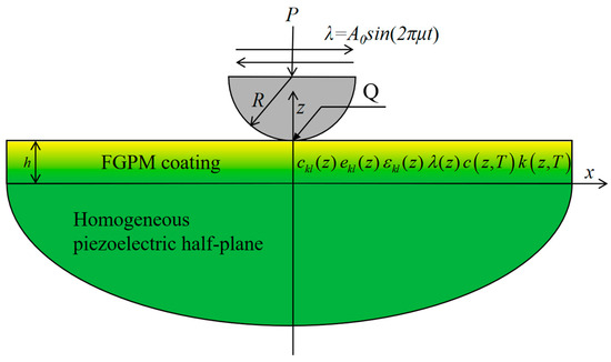
Figure 1.
Schematic diagram of reciprocating cyclic frictional sliding of a rigid conductive cylindrical punch on a functionally graded piezoelectric coated half-plane.
2.1. Temperature Field
It is assumed that the rigid cylindrical punch is a thermally insulated electrical conductor, such that all the heat flux generated by friction between the punch and the FGPM coating is transferred into the interior of the FGPM coating structure. The heat conduction equation can be expressed as:
where the subscript denotes the FGPM coating and the homogeneous piezoelectric half-plane, respectively; represents the temperature field; , , and stand for the thermal conductivity coefficients of the FGPM coating and homogeneous piezoelectric half-plane, respectively.
The thermal boundary conditions are as follows:
Given that the thermal conductivity is a function of z and exhibits temperature dependence, an analytical solution to Equation (3) is almost impossible to obtain.
2.2. Thermo-Electro-Elastic Field
Under the plane strain condition, the linear constitutive equations of the transversely isotropic FGPM coating and the homogeneous piezoelectric half-plane can be expressed as follows:
where are the stress components and electric displacement components of the FGPM coating and homogeneous piezoelectric half-plane, respectively; are the displacement components and electric potential, respectively; denote the elastic constants, piezoelectric constants, and dielectric constants, respectively; and are the thermal expansion coefficients and pyroelectric coefficients.
Neglecting body forces and body charges, the equilibrium equations and Maxwell’s equations for the FGPM coating and the homogeneous piezoelectric half-plane can be expressed as:
Substituting the constitutive equations into the above system of equations yields the following:
Due to the arbitrary functional variation of material parameters in the FGPM coating and the difficulty in obtaining an analytical solution for the temperature field, deriving analytical solutions for the above Equations (11)–(13) is difficult or even impossible. This makes the current analysis of thermo-electro-electrical coupled frictional contact problems highly challenging. In view of this, the finite element method is employed to investigate the thermoelastic sliding friction and wear problem of FGPM-coated half-plane with arbitrarily varying material properties.
3. Finite Element Model
A finite element model for thermoelastic sliding friction and wear was developed using ABAQUS 2020 to simulate the contact between a rigid conductive cylindrical punch and an FGPM-coated homogeneous piezoelectric half-plane. The radius of the cylindrical punch is . The homogeneous piezoelectric half-plane, with dimensions of , is treated as a half-plane due to its significantly larger size compared to the contact area. The FGPM coating thickness is .
3.1. The Thermo-Electro-Elastic Contact Model
The master–slave algorithm is adopted for contact discretization, where the master and slave surfaces are selected according to two common criteria: (1) the surface with higher stiffness serves as the master surface; and (2) the surface with a coarser mesh is designated as the master surface. Accordingly, the rigid punch surface is assigned as the master surface, while the coating surface is defined as the slave surface. Within the contact properties, the proportion of frictional heat allocated to the slave surface is set to 100%, implying that all heat is transferred to the half-plane. The normal contact behavior of the contact interface is defined as “hard contact”, and the tangential behavior is modeled using the penalty method based on Coulomb’s friction law.
A combination of user-defined subroutines (UMAT, UXEXPAN, and UMATHT) is employed to model the arbitrary gradient variation of the thermo-electro-elastic parameters of the FGPM coating, accounting for the temperature dependence of its thermal parameters. The transient thermal–mechanical coupling method is adopted to solve the thermoelastic frictional contact problem.
Given the negligible influence of the inverse piezoelectric effect and the independence of piezoelectric module from the thermal–mechanical coupling process, a sequential coupling strategy is adopted. After completing the thermal–mechanical analysis, the worn model is imported, and the element types are switched from planar temperature-displacement coupled elements (CPE4T and CPE3T) to bilinear plane stress piezoelectric elements (CPS4E and CPS3E) to perform the piezoelectric analysis.
3.2. Mesh Generation and Independence Study
We adopted 3-node/4-node planar temperature-displacement coupled elements (CPE3T/CPE4T) and 3-node/4-node bilinear plane stress piezoelectric elements (CPS4E and CPS3E) as primary element types. This choice balances computational accuracy and efficiency. The core idea was to employ a gradient meshing strategy, where regions with high stress/strain gradients (contact surfaces) were discretized with a finer mesh, while other regions with relatively uniform stress distribution were meshed with a coarser mesh to reduce the total number of elements and computational cost.
The computational domain was discretized in HyperMesh, in which the mesh density was regulated by defining “seeds”—predefined node distribution points along the edges and surfaces of the model. These seeds govern the local element size and spatial distribution, enabling targeted refinement in critical regions. A mesh sensitivity study was performed by progressively reducing the local seed size from 1 mm to 0.005 mm (Figure 2). The results showed that the maximum von Mises stress converged when the seed size reached 0.01 mm, with variations of less than 2%. Consequently, a local seed size of 0.01 mm was selected for local refinements for all subsequent simulations to balance accuracy and computational cost. Therefore, a based seed size of 3 mm was applied to the entire model, and a much finer local seed size of 0.01 mm was applied in regions of high-stress concentration (the contact area). In this case, the friction contact model is discretized with a total of 26,545 elements—26,351 CPE4T and 97 CPE3T elements. The finite element model is shown in Figure 3. Figure 3b,c present a local refined, magnified views of the contact area.
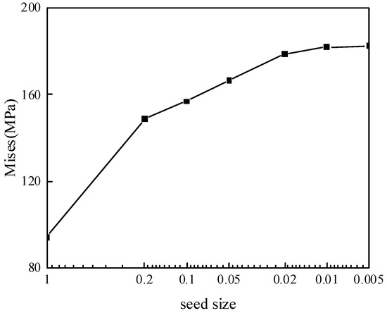
Figure 2.
Variation of Mises stress with the mesh density (seed size) of the contact area.
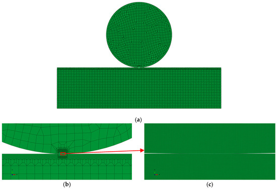
Figure 3.
Finite element mesh division of frictional contact between punch and FGPM coating structure (a) and local enlarged views of contact area (b,c).
During mesh generation, a global seed size of 3 mm and a finer local size of 0.01 mm in regions of high stress concentration (the contact area) were adopted. To verify that this significant variation in seed size would not compromise the simulation results, additional post-processing analyses were conducted on the transition zone between the coarse and fine meshes. Figure 4 presents the von Mises stress distribution of the post-analyzed transition zone. It is shown that the stress distribution exhibits stability and continuity, with no unphysical abrupt jumps or oscillations observed. This confirms that the simulation results remain unaffected by the mesh density variation.
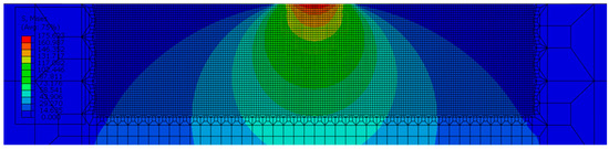
Figure 4.
Von Mises stress distribution of the post-analyzed transition zone.
3.3. The Wear Modeling
Since the punch is assumed to be rigid with no self-wear, all wear quantification focuses exclusively on the surface of coating material. This approach avoids the complexity of calculating “two-body wear”, ensuring that the quantified results directly reflect the coating’s intrinsic performance. In the finite element calculation, a modified Archard wear model was employed to characterize the surface geometric evolution induced by material wear, based on the contact characteristics of the “rigid punch- piezoelectric coating structure”. The Archard wear model was implemented via the well-established UMESHMOTION subroutine. When coupled with the Arbitrary Lagrange–Euler (ALE) adaptive meshing technique, this approach enables the mesh to remain independent of the model’s motion while preserving its original topology.
The Archard wear model correlates wear severity with contact pressure and relative slip. Given that the pressure varies with the sliding position, the integral form of the model was applied. The wear depth at time t is expressed as follows:
where denotes the contact pressure at time t, represents the slip increment, and is the wear coefficient with a value range of [18,29].
In the finite element software ABAQUS, the Archard wear formula is implemented via the user-defined subroutine UMESHMOTION. The wear accumulation rule is defined as follows: the total sliding process is divided into multiple incremental steps; at each step, the wear induced in that step is calculated based on the instantaneous contact pressure and sliding distance, and the mesh geometry of the piezoelectric layer (e.g., nodal coordinate offsets in the worn region) is updated in real time. This approach enables the simulation of the gradual surface material loss of the piezoelectric coating during sliding process.
4. Model Validation
To verify the model accuracy, the piezoelectric effect was neglected, and the thermoelastic sliding frictional contact between the conductive cylindrical punch and the FGM-coated half-plane was simulated using ABAQUS 2020. In the model, the coating’s upper layer consists of zirconia (), while the lower layer (i.e., the half-plane) is composed of 6061-T6 aluminum alloy. A comparison between the finite element results and the theoretical solutions from Zhou et al. [26] is shown in Figure 5. It can be observed that the finite element results exhibit good agreement with the theoretical solutions.
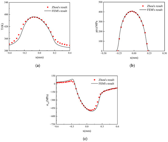
Figure 5.
Comparison between the finite element results and those by Zhou et al. [26] on (a) surface temperature; (b) surface contact pressure; (c) in-plane stress.
Neglecting frictional and wear effects, the frictionless contact problem between the conductive cylindrical punch and the FGPM coating structure was analyzed. The thermo-electro-elastic properties of the FGPM coating vary exponentially along the thickness direction, with the lower layer consisting of PZT-4. A comparison between the finite element results and the theoretical solutions from Ke et al. [5] is presented in Figure 6, demonstrating good agreement between the two sets of results.
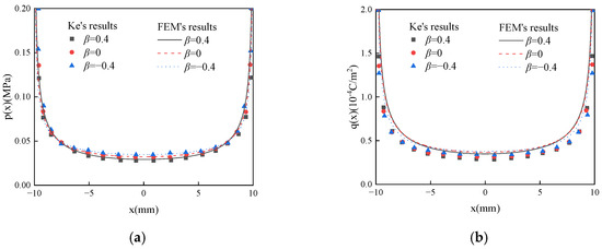
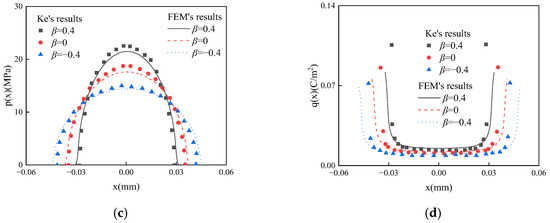
Figure 6.
Comparison between the finite element results and the results by Ke et al. [5] on (a) surface contact pressure; (b) surface electric charge distribution under a flat punch; (c) surface contact pressure and (d) surface electric charge distribution under a cylindrical punch.
5. Numerical Results and Discussion
In this section, thermoelastic sliding friction and wear of a specified FGPM coating structure is developed using ABAQUS 2020. The homogeneous piezoelectric half-plane is PZT-4 ceramic, whose material properties are detailed in Table 1 and Table 2. Note that two key thermophysical parameters—specific heat capacity and thermal conductivity—exhibit temperature dependence. At the interface (z = −h), the material properties of the piezoelectric half-plane and the FGPM layer are continuous and identical. The FGPM coating thickness is h = 1 mm. A normal load P = 100 N is applied to the nodes of the punch, which reciprocates in the x-direction with an amplitude A0 = 0.15 mm and a frequency f = 40 Hz. The bottom of the homogeneous piezoelectric half-plane is fixed. The initial temperature is T = T0 = 300 K. The friction coefficient is f = 0.3.

Table 1.
Elastic modulus, piezoelectric constant and dielectric constant of PZT-4 [5].
Table 2.
Thermal material parameters of PZT-4 [30,31,32].
Given that the thermo-electro-elastic material parameters of the FGPM coating can vary arbitrarily with depth, we assume an exponential along the coating thickness direction, as expressed in Equation (15):
where are the elastic constants, piezoelectric constants, dielectric constants, thermal expansion coefficients, specific heat capacity, and thermal conductivities, respectively.
5.1. The Effect of Wear
Figure 7 illustrates the influence of wear and cycle number on the thermal sliding frictional contact surface characteristics of the FGPM coating structure. As shown in figures, significant changes occur in the surface contact pressure (Figure 7a), surface temperature T (Figure 7b), surface charge (Figure 7c), and surface electric displacement (Figure 7d) when wear takes place. With increasing cycles, the distribution curves gradually become progressively smoother within the contact area. Additionally, the contact area expands gradually, whereas the maximum values of both contact stress and surface temperature decrease.
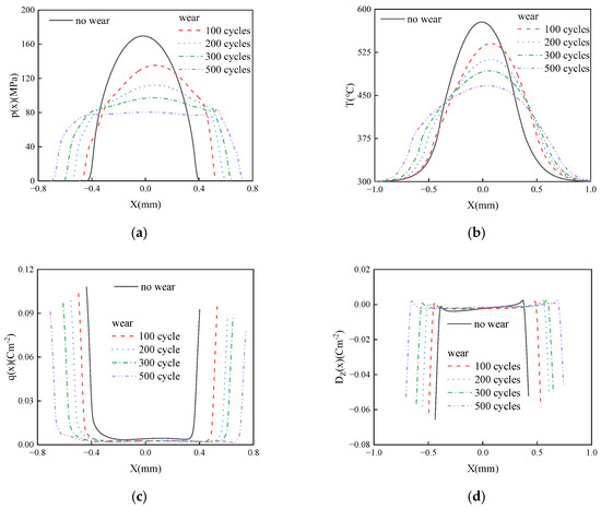
Figure 7.
The effect of wear on contact stress (a), contact surface temperature (b), surface charge distribution (c) and surface electric displacement (d) with βh = −0.5, f = 0.3.
The influence of wear and number of cycles on the in-plane stress and in-plane electric displacement of the FGPM coating structure is shown in Figure 8. Figure 8a illustrates that as wear occurs, both the distribution of in-plane stress and the contact area change; with the increase in the number of cycles n, the maximum tensile stress at the trailing end of the contact area and the maximum compressive stress within the contact area gradually decrease. As shown in Figure 8b, the in-plane electric displacement displays a singular at the edge of the contact area, with its maximum value decreasing as the number of cycles n increase. These numerical results demonstrate that wear has a significant impact on the thermo-electro-elastic coupled frictional contact characteristics.
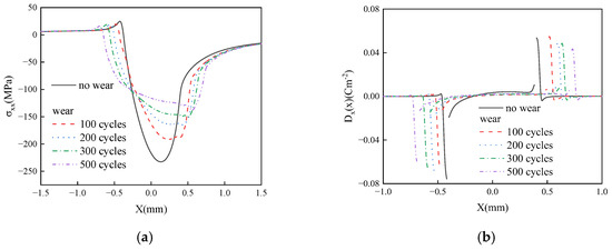
Figure 8.
The effect of wear on in-plane stress (a) and in-plane electric displacement (b) with βh = −0.5, f = 0.3.
The wear depth was directly quantified by comparing the coating’s surface topography before and after the sliding simulation. Since this study adopts an elastic model, the nodal coordinates of the coating surface were extracted at both the start and end of the analysis. The wear depth at any given node was then calculated as the vector difference in its out-of-plane displacement. This coordinate subtraction method provides a direct and unambiguous measure of the total material loss induced by wear. Figure 9 illustrates the effects of sliding cycles, gradient index and friction coefficient on wear depth. As shown in Figure 9a, both the depth and width of the wear increase significantly with the number of sliding cycles, indicating a clear cumulative wear effect. Figure 9b illustrates the effect of the gradient index: an increase in the gradient index leads to greater wear depth but a smaller worn area. This phenomenon is primarily attributed to the enhanced surface hardness associated with a higher gradient index, which concentrates contact stress more intensely in the central region and thereby exacerbating localized wear. In addition, the depth and width of the wear gradually decrease with the increase in the friction coefficient (Figure 9c).
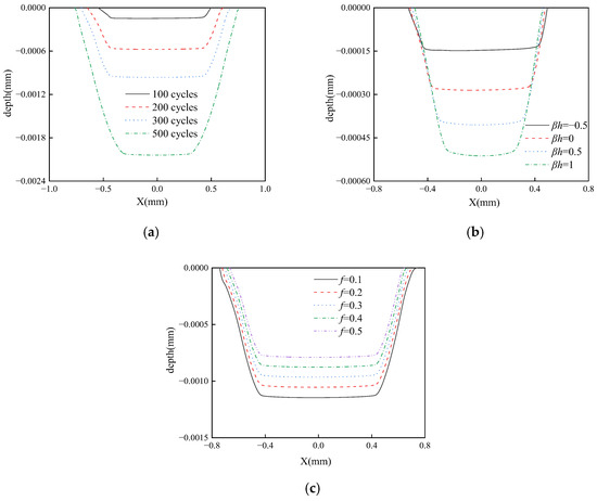
Figure 9.
The influence of cycle number on wear with βh = −0.5, f = 0.3 (a), influence of gradient index on wear with d = 300, f = 0.3 (b), influence of friction coefficient on wear with d = 300, βh = −0.5 (c).
5.2. The Effect of Gradient Index
Figure 10 illustrates the influence of the coating material gradient index n on the thermal sliding frictional contact surface characteristics of the FGPM coating structure. As shown in Figure 10a, due to the occurrence of wear, the contact area gradually decreases with an increase in the gradient index n, while the surface contact pressure within the contact area exhibits fluctuations. Meanwhile, the maximum value of the surface contact pressure increases as n increases, resulting in a corresponding gradual increase in the maximum temperature T within the contact area (Figure 10b). Figure 10c shows that the surface charge exhibits singularity at both ends of the contact area, with its maximum value decreasing as the gradient index n increases. Furthermore, the surface electric displacement (Figure 10d) also changes with the increase in n and fluctuates at the edge of the contact area.
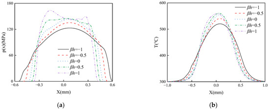
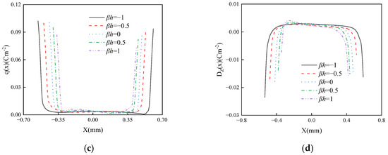
Figure 10.
The effect of gradient index on contact stress (a), contact surface temperature (b), surface charge distribution (c) and surface electric displacement (d) with d = 100, f = 0.3.
Figure 11 presents the influence of the coating material gradient index n on the in-plane stress and in-plane electric displacement of the FGPM coating structure. As shown in Figure 11a, the gradient index n has a significant impact on the in-plane stress. With the increase in the gradient index n, the maximum tensile stress at the trailing end of the contact area gradually decreases, while the maximum in-plane compressive stress within the area gradually increases. Figure 11b illustrates that the in-plane electric displacement exhibits singularity at the edge of the contact area, and its maximum value gradually decreases as n increases. The presence of such in-plane tensile stress, coupled with the singularity in electric displacement, can trigger crack initiation and electrical contact damage. These numerical results demonstrate that the thermo-electrical coupled frictional contact damage in piezoelectric materials can be effectively mitigated by appropriately adjusting the gradient index of the FGPM coating.
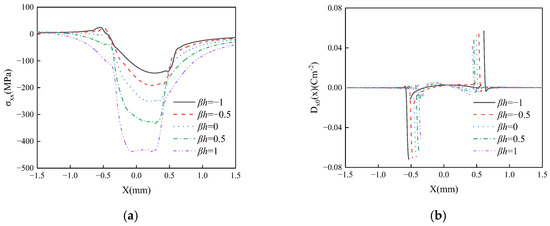
Figure 11.
The effect of gradient index on in-plane stress (a) and in-plane electric displacement (b) with d = 100, f = 0.3.
5.3. The Effect of the Coefficient of Friction
Figure 12 illustrates the influence of the friction coefficient on the thermal sliding frictional contact surface characteristics of the FGPM coating structure. As shown in the figure, the friction coefficient has a significant impact on the contact pressure, temperature, charge distribution, and electric displacement on the frictional contact surface. The maximum value of the surface contact pressure (Figure 12a) increases gradually with the friction coefficient, leading to a corresponding increase in the maximum value of the surface temperature T (Figure 12b) within the contact area. This behavior is primarily attributed to the fact that frictional heat is proportional to both contact pressure and the friction coefficient. In contrast, the friction coefficient has only a minor effect on the surface charge (Figure 12c) and surface electric displacement (Figure 12d) at both ends of the contact area.
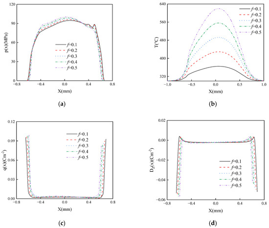
Figure 12.
The effect of coefficient of friction on contact stress (a), contact surface temperature (b), surface charge distribution (c) and surface electric displacement (d) with d = 300, βh = −0.5.
Figure 13 presents the influence of the friction coefficient on the in-plane stress and in-plane electric displacement of the FGPM coating structure. As shown in the figure, the friction coefficient exerts a considerable influence on both the in-plane stress (Figure 13a) and in-plane electric displacement (Figure 13b). With increasing friction coefficient, the maximum tensile stress and the maximum electric displacement at the trailing end of the contact area increase, while the maximum compressive stress within the contact area also gradually increases. These numerical results demonstrate that reducing the friction coefficient can effectively decrease the maximum tensile stress and electric displacement at the trailing end of the contact area, thereby alleviating the thermo-electrical coupled sliding frictional contact damage of piezoelectric materials.
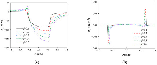
Figure 13.
The effect of coefficient of friction on in-plane stress (a) and in-plane electric displacement (b) with d = 300, βh = −0.5.
5.4. The Effect of Gradient Variation Form
To investigate the influence of different gradient variation forms of the coating on the thermal sliding frictional contact behavior of the FGPM coating structure, in addition to the thermo-electro-elastic parameters of the coating material varying exponentially as shown in Equation (15), we also consider three other gradient variation forms. Specifically, the thermo-electro-elastic parameters of the coating material vary along the coating thickness direction in the forms of the following power function, sine function, and cosine function as follows:
where βh = −1, n = −1.5, m = 0.64, η = −1.72.
Figure 14 and Figure 15 illustrate the influence of coating material gradient forms on the thermal sliding frictional contact surface characteristics of functionally graded piezoelectric material (FGPM) coating structures. As shown in Figure 14, different gradient forms of the coating material lead to variations in contact pressure, temperature, charge, and electric displacement on the sliding contact surface—particularly in surface contact pressure and surface temperature. For instance, the contact stress can be reduced by 6.1%, and the maximum surface temperature can be decreased by 7.06%. Among these gradient forms, the exponential law function form results in the smallest maximum surface temperature, as clearly demonstrated by maximum surface temperature data under different numbers of cycles in Table 3. Figure 15 indicates that the gradient form of the coating material also significantly affects the in-plane stress, with the sine function form exhibiting the smallest maximum tensile stress; corresponding numerical data are provided in Table 4. These numerical results demonstrate that optimizing the gradient variation form of the coating material can effectively reduce surface contact pressure and surface temperature, as well as controlling the maximum surface tensile stress, which is highly valuable for the design of high-performance piezoelectric material coatings.
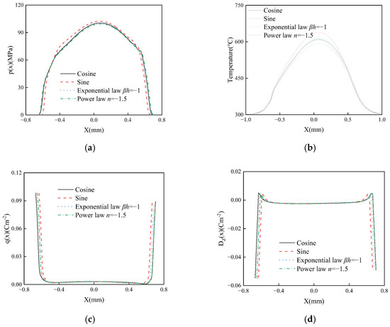
Figure 14.
The effect of gradient form on contact stress (a), contact surface temperature (b), surface charge distribution (c) and surface electric displacement (d) with d = 300, βh = −1, f = 0.3.
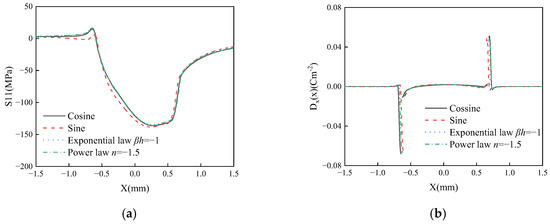
Figure 15.
The effect of gradient form on in-plane stress (a) and in-plane electric displacement (b) with d = 300, βh = −1, n = −1.5, f = 0.3.
Table 3.
Maximum surface temperatures corresponding to different gradient forms and cycle numbers.
Table 4.
Maximum in-plane stress values corresponding to different gradient forms and cycle numbers.
6. Conclusions
Based on the finite element method, this study investigates the thermoelastic sliding frictional contact and wear problems of FGPM-coated half-plane with arbitrarily varying thermo-electro-elastic parameters along the thickness direction under the action of a conductive cylindrical punch. Arbitrary gradient variation forms of the coating material are implemented using user-defined subroutines UMAT, UXEXPAN, and UMATHT. The effects of wear, number of cycles, coating material gradient index, friction coefficient, and coating gradient variation forms on the thermoelastic sliding frictional contact characteristics of the FGPM coating structure are systematically analyzed. The main conclusions of this work are summarized as follows:
1. When a rigid conductive cylindrical punch undergoes reciprocating sliding friction on the surface of the FGPM coating structure, significant changes occur in the contact pressure, temperature, electric potential, electric displacement, in-plane stress, and in-plane electric displacement on the frictional contact surface as wear takes place. Moreover, with increasing number of cycles from no wear to 500 cycles, contact area gradually expands, potentially increasing by about 43% and the maximum contact pressure decreases by about 52.6%, resulting in a corresponding reduction in the maximum surface temperature. Simultaneously, the maximum tensile stress and maximum electric displacement at the edge of the contact area also diminish with continued cycling.
2. As the coating material gradient index increases from −1 to 1, the maximum contact pressure and maximum temperature within the contact area gradually increase. In contrast, the maximum tensile stress and electric displacement at the edge of the contact area exhibit a decreasing trend. The presence of such in-plane tensile stress combined with electric displacement singularity, where the tensile stress may turn into compressive stress with the increase in the gradient index, and the electrical displacement correspondingly decreases by 26%. Such in-plane tensile stress accompanied by singular electrical displacement can trigger crack initiation and electrical contact damage. By appropriately adjusting the coating material gradient index, it is possible to reduce both tensile stress and electric displacement, thereby effectively mitigating the thermal sliding frictional contact damage and electrical contact degradation in piezoelectric materials.
3. Different gradient variation forms of the FGPM coating material lead to distinct thermal sliding frictional contact characteristics, particularly in surface contact pressure, surface temperature, and in-plane tensile stress. For instance, the contact stress can be reduced by 6.1%, and the maximum surface temperature can be decreased by 7.06%. Therefore, optimizing the gradient variation form of the FGPM coating material can effectively reduce surface contact pressure and surface temperature, while also controlling the maximum surface tensile stress—offering valuable insights for the design of high-performance piezoelectric material coatings.
Author Contributions
Conceptualization, J.L.; Methodology, J.L. and J.M.; Software, L.G.; Validation, L.G.; Formal analysis, J.M.; Investigation, L.G.; Resources, J.L.; Data curation, K.X.; Writing—original draft, L.G.; Writing—review & editing, K.X.; Visualization, K.X.; Supervision, J.M.; Project administration, J.L. and J.M.; Funding acquisition, J.L. All authors have read and agreed to the published version of the manuscript.
Funding
The work is supported by National Science Foundation of China under Grant no. 12172147.
Data Availability Statement
The original contributions presented in this study are included in the article. Further inquiries can be directed to the corresponding author.
Conflicts of Interest
No potential conflicts of interest were reported by the authors.
References
- Fu, J.; Li, F.-X. A comparative study of piezoelectric unimorph and multilayer actuators as stiffness sensors via contact resonance. Acta Mech. Sin. 2016, 32, 633–639. [Google Scholar] [CrossRef]
- Shin, H.; Ahn, H.; Han, D.-Y. Modeling and analysis of multilayer piezoelectric transformer. Mater. Chem. Phys. 2005, 92, 616–620. [Google Scholar] [CrossRef]
- Saito, R.; Hosobata, T.; Yamamoto, A.; Higuchi, T. Linear resonant electrostatic induction motor using electrical resonance with piezoelectric transducers. Mechatronics 2014, 24, 222–230. [Google Scholar] [CrossRef]
- Chen, C.; Zhao, C. A novel model of ultrasonic motors with effect of radial friction in contact mechanism. J. Electroceramics 2008, 20, 293–300. [Google Scholar] [CrossRef]
- Ke, L.-L.; Yang, J.; Kitipornchai, S.; Wang, Y.-S. Electro-mechanical frictionless contact behavior of a functionally graded piezoelectric layered half-plane under a rigid punch. Int. J. Solids Struct. 2008, 45, 3313–3333. [Google Scholar] [CrossRef]
- Ke, L.-L.; Wang, Y.-S.; Yang, J.; Kitipornchai, S. Sliding frictional contact analysis of functionally graded piezoelectric layered half-plane. Acta Mech. 2010, 209, 249–268. [Google Scholar] [CrossRef]
- Çömez, I.; Güler, M.A.; El-Borgi, S. Continuous and discontinuous contact problems of a functionally graded piezoelectric layer resting on a homogeneous piezoelectric half plane. Mech. Adv. Mater. Struct. 2022, 31, 2130–2143. [Google Scholar] [CrossRef]
- Singh, B.; Rokne, J.; Dhaliwal, R. The study of dynamic behavior of functionally graded piezoelectric materials and an application to a contact problem. Quart. Appl. Math 2007, 65, 155–162. [Google Scholar] [CrossRef]
- Kargarnovin, M.H.; Hashemi, R.; Emami, A.A. Electroelastic Analysis of FG Piezoelectric Structures under Thermo-Electro-Mechanical Loadings. Mech. Adv. Mater. Struct. 2013, 20, 11–27. [Google Scholar] [CrossRef]
- Vasiliev, A.S.; Volkov, S.S.; Aizikovich, S.M. Normal point force and point electric charge in a piezoelectric transversely isotropic functionally graded half-space. Acta Mech. 2016, 227, 263–273. [Google Scholar] [CrossRef]
- Ma, J.; Ke, L.-L.; Wang, Y.-S. Frictionless contact of a functionally graded magneto-electro-elastic layered half-plane under a conducting punch. Int. J. Solids Struct. 2014, 51, 2791–2806. [Google Scholar] [CrossRef]
- Ma, J.; Ke, L.-L.; Wang, Y.-S. Sliding Frictional Contact of Functionally Graded Magneto-Electro-Elastic Materials Under a Conducting Flat Punch. J. Appl. Mech. 2015, 82, 011009. [Google Scholar] [CrossRef]
- Ma, J.; El-Borgi, S.; Ke, L.-L.; Wang, Y.-S. Frictional contact problem between a functionally graded magnetoelectroelastic layer and a rigid conducting flat punch with frictional heat generation. J. Therm. Stress. 2016, 39, 245–277. [Google Scholar] [CrossRef]
- Liu, T.-J.; Zhang, C. Axisymmetric conducting indenter on a functionally graded piezoelectric coating. Int. J. Mech. Sci. 2016, 115–116, 34–44. [Google Scholar] [CrossRef]
- Liu, T.-J.; Li, P.; Zhang, C. On contact problem with finite friction for a graded piezoelectric coating under an insulating spherical indenter. Int. J. Eng. Sci. 2017, 121, 1–13. [Google Scholar] [CrossRef]
- Volkov, S.S.; Vasiliev, A.S.; Aizikovich, S.M.; Mitrin, B.I. Axisymmetric indentation of an electroelastic piezoelectric half-space with functionally graded piezoelectric coating by a circular punch. Acta Mech. 2019, 230, 1289–1302. [Google Scholar] [CrossRef]
- Zhou, X.; Liu, J.; Mao, J. Thermal Friction Contact Analysis of Graded Piezoelectric Coatings Under Conductive Punch Loading. Coatings 2025, 15, 222. [Google Scholar] [CrossRef]
- Shu, Y. Friction and Wear Experiments and Numerical Analysis of Piezoelectric Materials. Ph.D. Thesis, Beijing Jiaotong University, Beijing, China, 2023. [Google Scholar]
- Shu, Y.; Ke, L. Reciprocating Fretting Wear Behavior of Three Types of Piezoelectric Ceramics. In Proceedings of the 17th Academic Conference of Mechanics Societies from Seven Northern Provinces, Municipalities, and Autonomous Regions, Jiaozuo, China, 8 November 2018; pp. 124–125. [Google Scholar]
- Gahr, K.-H.Z.; Bundschuh, W.; Zimmerlin, B. Effect of grain size on friction and sliding wear of oxide ceramics. Wear 1993, 162–164, 269–279. [Google Scholar] [CrossRef]
- Mukhopadhyay, A.K.; Yiu-Wing, M. Grain size effect on abrasive wear mechanisms in alumina ceramics. Wear 1993, 162–164, 258–268. [Google Scholar] [CrossRef]
- He, C.; Wang, Y.S.; Wallace, J.S.; Hsu, S.M. Effect of microstructure on the wear transition of zirconia-toughened alumina. Wear 1993, 162–164, 314–321. [Google Scholar] [CrossRef]
- Rozmus, J.J. Electric Contacts: Theory and Application; Springer: Berlin/Heidelberg, Germany, 2010; Available online: https://link.springer.com/book/10.1007/978-3-662-06688-1 (accessed on 14 July 2025).
- Burwell, J.T.; Strang, C.D. On the Empirical Law of Adhesive Wear. J. Appl. Phys. 1952, 23, 18–28. [Google Scholar] [CrossRef]
- Archard, J.F. Contact and Rubbing of Flat Surfaces. J. Appl. Phys. 1953, 24, 981–988. [Google Scholar] [CrossRef]
- Zhou, J.-L.; Shen, F.; El-Borgi, S.; Ke, L.-L. Thermo-elastoplastic sliding frictional contact and wear analysis of FGM-coated half-planes. Acta Mech. 2024, 235, 4943–4960. [Google Scholar] [CrossRef]
- Yue, T.; Abdel Wahab, M. Finite element analysis of fretting wear under variable coefficient of friction and different contact regimes. Tribol. Int. 2017, 107, 274–282. [Google Scholar] [CrossRef]
- Zhan, W.; Huang, P. Numerical analysis of time-varying wear with elastic deformation in line contact. Friction 2019, 7, 143–152. [Google Scholar] [CrossRef]
- Khanna, R.; Basu, B. Sliding Wear Properties of Self-Mated Yttria-Stabilized Tetragonal Zirconia Ceramics in Cryogenic Environment. J. Am. Ceram. Soc. 2007, 90, 2525–2534. [Google Scholar] [CrossRef]
- Hooker, M.W. Properties of PZT-Based Piezoelectric Ceramics Between −150 and 250 °C; NASA: Washington, DC, USA, 1998. [Google Scholar]
- Tachibana, M.; Bourgès, C.; Mori, T. Thermal conductivity of lead zirconate titanate PbZr1−xTixO3. Appl. Phys. Express 2023, 16, 101002. [Google Scholar] [CrossRef]
- Liu, W.; Ko, J.S.; Zhu, W. Preparation and properties of multilayer Pb(Zr,Ti)O3/PbTiO3 thin films for pyroelectric application. Thin Solid Film. 2000, 371, 254–258. [Google Scholar] [CrossRef]


Disclaimer/Publisher’s Note: The statements, opinions and data contained in all publications are solely those of the individual author(s) and contributor(s) and not of MDPI and/or the editor(s). MDPI and/or the editor(s) disclaim responsibility for any injury to people or property resulting from any ideas, methods, instructions or products referred to in the content. |
© 2025 by the authors. Licensee MDPI, Basel, Switzerland. This article is an open access article distributed under the terms and conditions of the Creative Commons Attribution (CC BY) license (https://creativecommons.org/licenses/by/4.0/).