Article

A Robust Optimal Control Strategy for PMSM Based on VGPDO and Actor-Critic Neural Network Against Flux Weakening and Mismatched Load Torque

College of Information Science and Engineering, Northeastern University, Shenyang 110819, China
*
Author to whom correspondence should be addressed.
Mathematics 2025, 13(21), 3387; https://doi.org/10.3390/math13213387
Submission received: 20 August 2025 / Revised: 8 October 2025 / Accepted: 13 October 2025 / Published: 24 October 2025

Abstract

In this paper, a novel robust optimal control strategy is proposed for permanent magnet synchronous motors (PMSMs), simultaneously addressing two critical challenges in speed regulation: flux linkage degradation during long-term operation and abrupt load torque variations. The robust optimal control strategy is implemented through a combination of feedforward control and feedback control. A novel Variable-Gain Proportional Disturbance Observer (VGPDO) is proposed to simultaneously estimate time-varying flux linkage and torque disturbances in PMSM systems. The estimated disturbances are then compensated via a feedforward control loop, significantly improving the system’s robustness against parameter variations and external load changes. An optimal controller based on an actor-critic neural network provides feedback for optimal control performance. The uniform ultimate boundedness (UUB) of the proposed strategy is proved through Lyapunov stability analysis, and comprehensive simulation studies demonstrate the efficacy of both the proposed VGPDO and the proposed robust optimal control strategy.

1. Introduction

Owing to their superior power density, wide speed regulation range, compact structure, and high reliability, Permanent magnet synchronous motors (PMSMs) have been widely adopted in high-tech industries such as aerospace and new energy vehicles. The control strategies for PMSM have evolved significantly with the continuous development of control theory. With the advancement of modern industry, there is an increasing demand for enhanced control performance, achieving both robustness and optimality in PMSM speed control, which plays a crucial role in industrial production.
An effective PMSM control strategy should typically achieve optimality to minimize energy consumption while maintaining robustness to ensure long-term stable and efficient operation of the equipment. For PMSM speed regulation, conventional control strategies such as PID, sliding mode control, H control, model reference adaptive control, and backstepping control [1,2,3,4,5,6,7,8,9] have been widely adopted. However, these methods fail to achieve process optimality in terms of energy efficiency and dynamic performance. To achieve optimal control for the nonlinear PMSM system, it is necessary to formulate the Hamilton–Jacobi–Bellman (HJB) equation based on the cost function. However, these equations typically lack analytical solutions and pose significant challenges for numerical computation.
With the advancement of computational capabilities, reinforcement learning (RL)—also known as adaptive dynamic programming (ADP)—has emerged as a powerful tool for approximating solutions to the HJB equation, thereby enabling optimal control in practical applications [10,11,12,13,14,15,16]. Recent advances in PMSM optimal control based on ADP have demonstrated the effectiveness in [17,18,19,20,21], which utilize two neural networks to approximate the value function (Critic) and optimal control policy function (Actor), respectively, thereby circumventing the numerical challenges of directly solving HJB equations. Theoretical analysis proves that gradient-based weight updating ensures UUB stability within a neighborhood of ideal parameters [22].
Standard ADP methods struggle with HJB estimation during sudden parameter changes. Real-time identification and compensation of PMSM internal uncertainties and external disturbances constitute an effective solution. Prior works extensively address mismatched load torque effects: ref. [18] developed a serial extended state observer (ESO) for load torque observation; ref. [19] constructed a disturbance observer to estimate the load torque; ref. [20] proposed a load torque estimator that incorporates actuator error compensation to guarantee system stability. However, to ensure long-term operational stability of permanent magnet synchronous motors, it is essential to account for flux linkage deterioration effects, which necessitates real-time, accurate observation of motor flux linkage parameters. Numerous studies have developed dedicated flux linkage observers [23,24,25] and load torque observers [17,18,26,27] for PMSM. However, research on designing integrated observers capable of simultaneously estimating both flux linkage and load torque to ensure long-term stable operation in PMSM speed control systems remains scarce.
To solve the above problem, a variable-gain proportional disturbance observer (VGPDO), which simultaneously estimates both the flux linkage deterioration and external load torque disturbances, is proposed in this paper. Meanwhile, a robust optimal speed control strategy is proposed for PMSM. The strategy deploys a feedforward controller in the PMSM control system, which utilizes the flux linkage and torque estimates obtained from VGPDO to compensate for disturbances in real time, thereby transforming the PMSM dynamic system into an error dynamic system with disturbance rejection robustness. Furthermore, an actor-critic network-based optimal controller is implemented in this error dynamic system to stabilize the system and achieve optimal control.
The remainder of this paper is organized as follows: Section 2 derives the PMSM error dynamic equations with feedforward compensation for flux linkage and load torque variations. Section 3 develops the VGPDO to estimate both flux linkage and load torque in PMSM. Section 4 presents the actor-critic-based optimal controller design. Section 5 performs simulation studies with a comprehensive analysis. Finally, Section 6 concludes the paper by summarizing key contributions.
The main contributions of this paper are summarized as follows:
To mitigate flux linkage degradation in PMSM control systems during prolonged load operation, a VGPDO is proposed to simultaneously estimate torque and flux linkage disturbances, thereby enhancing system robustness.
To achieve optimality and robustness in PMSM speed regulation under varying load torque and flux linkage conditions, a robust optimal control strategy is proposed, which integrates feedforward-based VGPDO compensation with an actor-critic neural network-based optimal speed controller.
Comprehensive simulations are conducted to validate the effectiveness of the VGPDO and robust optimal control strategy.

2. System Descriptions

As proposed in [19], the PMSM dynamics can be represented as:
ω ˙ = n p ψ f J i q B J ω 1 J T L i ˙ q = R s L i q n p ω i d n p ψ f L ω + 1 L u q i ˙ d = R s L i d + n p ω i q + 1 L u d
where w , J , T L and B are the angular velocity, inertia, load torque and viscous friction coefficient of PMSM, L , R s and n p are the stator inductance, stator resistance, and number of pole pairs, respectively. i q and u q are the q-axis stator current and voltage. i d and u d are the d-axis stator current and voltage. ψ f is the rotor flux linkage. The PMSM states w, i q , and i d are assumed to be measurable.
When PMSM operates over an extended period, demagnetization effects must be considered. Let Δ ψ denote the variation in magnetic flux and let ψ s represent the initial magnetic flux, hence we have:
ψ f = ψ s + Δ ψ
For convenience in the following analysis, we take n p ψ f J as m 1 , B J as m 2 , 1 J as m 3 , R s L as m 4 , n p ψ f L as m 5 , n p as m 6 and 1 L as m 7 . We also define:
m 1 n p ψ s J ; m 5 n p ψ s L m ^ 1 n p ψ s + Δ ψ ^ J ; m ^ 5 n p ψ s + Δ ψ ^ L m ˜ 1 m 1 m ^ 1 ; m ˜ 5 m 5 m ^ 5
In order to achieve our tracking goals, we introduce:
w ˜ w w d i ˜ q i q i ^ q
where w d represents the reference speed, i ^ q represents the virtual control input and is given by:
i ^ q = m 2 ω d + m 3 T ^ L + ω ˙ d m ^ 1
To facilitate the practical implementation of the actor-critic neural network-based optimal speed controller, the system described above is restructured via feedforward compensation. Hence, the control inputs u d and u q are decoupled into:
u q = u ^ c q + u s q u d = u ^ c d + u s d
where u s q and u s d denote the stabilizing terms generated by the actor-critic neural network-based optimal speed controller, while u ^ c d and u ^ c q represent terms which are defined as:
u ^ c q = 1 m 7 ( m 4 i ^ q + m ^ 5 ω d + m 6 ω d i d + i ^ ˙ q ) u ^ c d = 1 m 7 ( m 6 ω d i ˜ q + m 6 ω i ^ q )
By substituting (2)–(7) into Model (1), a new error dynamics model can be derived:
w ˜ ˙ = m 1 i ˜ q m 2 ω ˜ m 3 T ˜ L + m ˜ 1 m ^ 1 m 2 ω d + m 3 T ^ L + ω ˙ d i ˜ ˙ q = m 5 w ˜ k 4 i ˜ q + m 7 u s q m 6 ω ˜ i d m ˜ 5 ω d i ˙ d = m 4 i d + m 7 u s d + m 6 ω ˜ i ˜ q
To facilitate further analysis, the Model (8) can be rewritten in the following form:
x ˙ = f x + g u + δ
where:
x ω ˜ i ˜ q i d T , u u s q u s d T ; f ( x ) m 2 ω ˜ + m 1 i ˜ q m 5 ω ˜ m 4 i ˜ q m 6 ω ˜ i d m 4 i d + m 6 ω ˜ i ˜ q , g 0 0 m 7 0 0 m 7 ; δ m 3 T ˜ L + m ˜ 1 m ^ 1 m 2 ω d + m 3 T ^ L + ω ˙ d m ˜ 5 ω d 0 T

3. Variable-Gain Proportional Disturbance Observer Design

To ensure long-term stable operation of PMSM, an advanced observer capable of capturing both external disturbances and internal parameter variations is essential in a robust optimal control strategy. In this paper, we explicitly address abrupt load torque variations and flux linkage degradation, which are two primary disturbances occurring during prolonged PMSM operation, to enhance system robustness.
Considering the variation in magnetic flux, Model (1) can be reformulated by substituting (2) and (3), yielding:
ω ˙ = m 1 i q m 2 ω m 3 T L + n 1 i q Δ ψ i ˙ q = m 4 i q m 6 ω i d m 5 ω + m 7 u q + n 2 ω Δ ψ i ˙ d = m 4 i d + m 6 ω i q + m 7 u d
where n 1 n p J , n 2 n p L .
For simplicity, the above model (11) can be further expressed as:
z ˙ = A z t + h z + B u + E ( z ) d
with:
z z 1 z 2 z 3 T w i q i d T ; d Δ ψ T L T ; A m 2 m 1 0 m 5 m 4 0 0 0 m 4 , B 0 0 m 7 0 0 m 7 ; h z 0 m 6 z 1 z 3 m 6 z 1 z 2 , E z n 1 z 2 m 3 n 2 z 1 0 0 0 .
Based on model (12), a disturbance observer is proposed as follows:
d ^ = s + p p ˙ = l z z ˙ s ˙ = l z E ( z ) s l z A z + h ( z ) + B u + E ( z ) p
where l ( z ) is an undetermined matrix function expressed as: l x = l 11 l 12 l 13 l 21 l 22 l 23 .
Defining the estimation error as d ˜ = d d ^ , and combining (12) and (14), we obtain:
d ˜ ˙ = d ^ ˙ + d ˙ = l z E z s + l z A z + h ( z ) + B u + E z p l z z ˙ + d ˙ = l z E z s + l z A z + h ( z ) + B u + E z p l z A z + h ( z ) + B u + E z d + d ˙ = l z E z s + l z E z p E z d + d ˙ = l z E z d s p + d ˙ = l z E z d d ^ + d ˙ = l z E z d ˜ + d ˙
To guarantee the bounded convergence of d ˜ , the following condition must be satisfied:
l x E x = l 11 l 12 l 13 l 21 l 22 l 23 n 1 z 2 m 3 n 2 z 1 0 0 0 = n 1 z 2 l 11 + n 2 z 1 l 12 m 3 l 11 n 1 z 2 l 21 + n 2 z 1 l 22 m 3 l 21 > 0
Considering the safety margins α 1 and α 2 , we set:
n 1 z 2 l 11 + n 2 z 1 l 12 m 3 l 11 n 1 z 2 l 21 + n 2 z 1 l 22 m 3 l 21 α 1 0 0 α 2 > 0
A feasible solution is given as follows:
l 11 = l 13 = l 23 = 0 l 12 = α 1 n 2 z 1 l 21 = α 2 m 3 l 22 = n 1 z 2 n 2 z 1 α 2 m 3
Assumption 1.
1.
The load torque of PMSM and its rate are bounded by: T L γ 1 T ˙ L Υ 1 .
2.
The flux linkage of PMSM variation rate is bounded by: Δ ψ ˙ Υ 2 .
3.
The reference speed and its derivative for PMSM are bounded as follows: w d γ 3 w ˙ d Υ 3 .
Remark 1. 
The above assumptions are practically reasonable for: (1). In real-world mechanical systems, the load torque is always finite due to physical limitations and typically varies smoothly due to inertia and damping effects. (2). The flux linkage variation rate Δ ψ ˙ is naturally constrained by the physical constraints of magnetic domain reorientation and limited energy available for instantaneous demagnetization. (3). Reference speed w d and acceleration w ˙ d are bounded by both the motor’s rated specifications and practical motion control needs.
Theorem 1. 
When applying the VGPDO (14) to Model (12) for flux linkage deterioration and disturbance torque estimation, the estimation error is bounded as follows under Assumption 1:
T ˜ L Υ 1 1 + α 1 2 Δ ψ ˜ Υ 2 1 + α 2 2
Notably, the VGPDO estimation error exhibits asymptotic stability under constant load torque and flux linkage conditions.
Furthermore, the parameter δ in (10) remains bounded (the detailed formulation is given in (A8)).
Proof of Theorem 1. 
The complete mathematical derivations are provided in Appendix A.1. □

4. Actor-Critic Network-Based Optimal Controller Design

The optimal controller u is designed to guarantee speed tracking while minimizing the following cost function:
V ( x 0 ) = 0 r ( x ( τ ) , u ( τ ) ) d τ
where r ( x , u ) = Q ( x ) + u T R u and Q ( x ) is a positive definite function, R is a symmetric positive definite constant matrix, and x 0 denotes the initial state of x.
According to [19], the minimization of this cost function can be achieved through the Hamiltonian function. The corresponding Hamiltonian for the cost function V ( x ) yeilds:
H x , u , V x = r x , u + V x T f x + g u + δ
where V x is defined as: V x d V d x .
Define the optimal cost function as:
V ( x 0 ) = min u 0 r ( x ( τ ) , u ( x ( τ ) ) ) d τ
According to [28], the optimal controller u and optimal cost function V x satisfy:
0 = Q ( x ) + u T R u + V x T f ( x ) + g u + δ
The optimal control input u can be solved as:
u = arg min μ [ H ( x , μ , V x ) ] = 1 2 R 1 g T V x .
Based on [28], the cost function V ( x ) can be expanded as an infinite series of basis functions ζ i multiplied by their corresponding coefficients c i :
V ( x ) = i = 1 c i ζ i ( x ) = i = 1 N c i ζ i ( x ) + i = N + 1 c i ζ i ( x )
For notational simplicity, we introduce:
V ( x ) C 1 ζ + i = N + 1 c i ζ i ( x )
where C 1 c 1 c 2 c n T , ζ ζ 1 ζ 2 ζ n T .
According to [22,29], there exist unknown neural network weights W c and an neural network basis function vector ζ ( x ) that can approximate the cost function V ( x ) as:
V ( x ) = W c T ζ ( x ) + ε ( x )
where ζ : R n R N and N represents the number of neurons in the hidden layer, and ε is the approximation error.
Substituting (27) into the Hamiltonian function (21), we obtain:
H ( x , u , W c ) = W c T ζ ( f + g u ) + Q ( x ) + u T R u = ε H
where the residual error ε H is expressed as:
ε H = ε T f + g u W c T ζ δ = ( C 1 W c ) T ζ ( f + g u ) i = N + 1 c i ζ i ( x ) ( f + g u ) W c T ζ δ
Similarly, the estimated cost function V ^ ( x ) obtained using the estimated weights W ^ c can be expressed as:
V ^ ( x ) = W ^ c T ζ ( x )
and the corresponding Hamiltonian function of V ^ ( x ) is given by:
H ( x , u , W ^ c ) = W ^ c T ζ ( f + g u ) + Q ( x ) + u T R u = e 1
e 1 = W ˜ c T ζ ( f + g u ) + ε H
where we have W ˜ c W c W ^ c .
To minimize the estimation error W ˜ c , we define E 1 = 1 2 e 1 T e 1 . Following [19], the normalized gradient descent algorithm yields:
W ^ ˙ c = a 1 E 1 W ^ c = a 1 σ 1 ( σ 1 T σ 1 + 1 ) 2 [ σ 1 T W ^ c + Q ( x ) + u T R u ]
where a 1 is a tunable parameter and σ 1 = ζ ( f + g u ) , while σ 1 T σ 1 + 1 2 is used for normalization.
To achieve optimal control, a neural network-based estimator for the optimal controller u 2 is given by:
u 2 ( x ) = 1 2 R 1 g T ( x ) ζ T W ^ a
where W ^ a denotes the estimate of W c with the estimation error of W a defined as W ˜ a W a W ^ a .
The update law of W ^ a is designed as:
W ^ ˙ a = a 2 η a W ^ a η c W ^ c 1 4 G W ^ a m T W ^ c
where a 2 is a tunable parameter and we have:
G ζ g R 1 g T ζ T
σ 2 ζ ( f + g u 2 )
m σ 2 ( σ 2 T σ 2 + 1 ) 2
Assumption 2.
1. 
f(x) is Lipschitz, and g(x) is bounded by a constant:
f ( x ) < γ f x g ( x ) < γ g
2. 
The NN approximate error and its gradient are bounded by:
ε < γ ε ε < γ ε x
3. 
The NN basis functions and their gradients are bounded by:
ζ ( x ) < γ ζ ζ ( x ) < γ ζ x
Remark 2. 
These assumptions are fundamentally grounded in the optimal control framework based on ADP [30,31,32], with rigorous theoretical foundations established in [28] and practical validations demonstrated in [20].
Theorem 2. 
For the PMSM model (1) equipped with the feedforward controller (7) and the feedback controller (34), the update law of the critic neural network is designed as:
W ^ ˙ c = a 1 σ 2 ( σ 2 T σ 2 + 1 ) 2 ( σ 2 T W ^ c + Q + u 2 T R u 2 ) ,
and the updating law of the actor neural network as:
W ^ ˙ a = a 2 ( η a W ^ a η c W ^ c 1 4 G W ^ a m T W ^ c ) ,
and η c > 0 and η a > 0 are tuning parameters satisfy LMI:
ϵ I 0 0 0 I 1 2 η c 1 8 m s G W c T 0 1 2 η c 1 8 m s G W c η a 1 8 G W c m T + m W c T G > 0
let Assumption 2 hold, and there exists a positive integer N 0 such that the number of the hidden layer units N > N 0 , then, the error dynamic system states x, the critic neural network approximate error W ˜ c , and the actor neural network approximate error W ˜ a are uniformly ultimately bounded.
Proof of Theorem 2. 
The complete mathematical derivations are provided in Appendix A.2. □
Figure 1 illustrates the complete flowchart of the proposed robust optimal control strategy for clearer demonstration.

5. Simulation Results

To evaluate the effectiveness of the proposed approach, Software-in-the-Loop (SIL) simulations were conducted within the MATLAB/Simulink (R2023b) environment to implement and evaluate both the VGPDO algorithm and the robust optimal control strategy. The simulation parameters for PMSM in this study are consistent with those in [18,19], with detailed parameter values presented in Table 1.
In simulation case 1, to demonstrate the effectiveness of the proposed VGPDO capable of simultaneous torque and flux estimation, two benchmark methods are employed for comparison: (1) a sliding-mode flux observer (SMO) algorithm from [25], which has been adopted by Simulink as a standard benchmark module, and (2) a load torque nonlinear disturbance observer (NDO) from [19]. Notably, the NDO explicitly accounts for demagnetization effects through compensation, where the compensation quantity is derived from the flux linkage estimation provided by SMO.
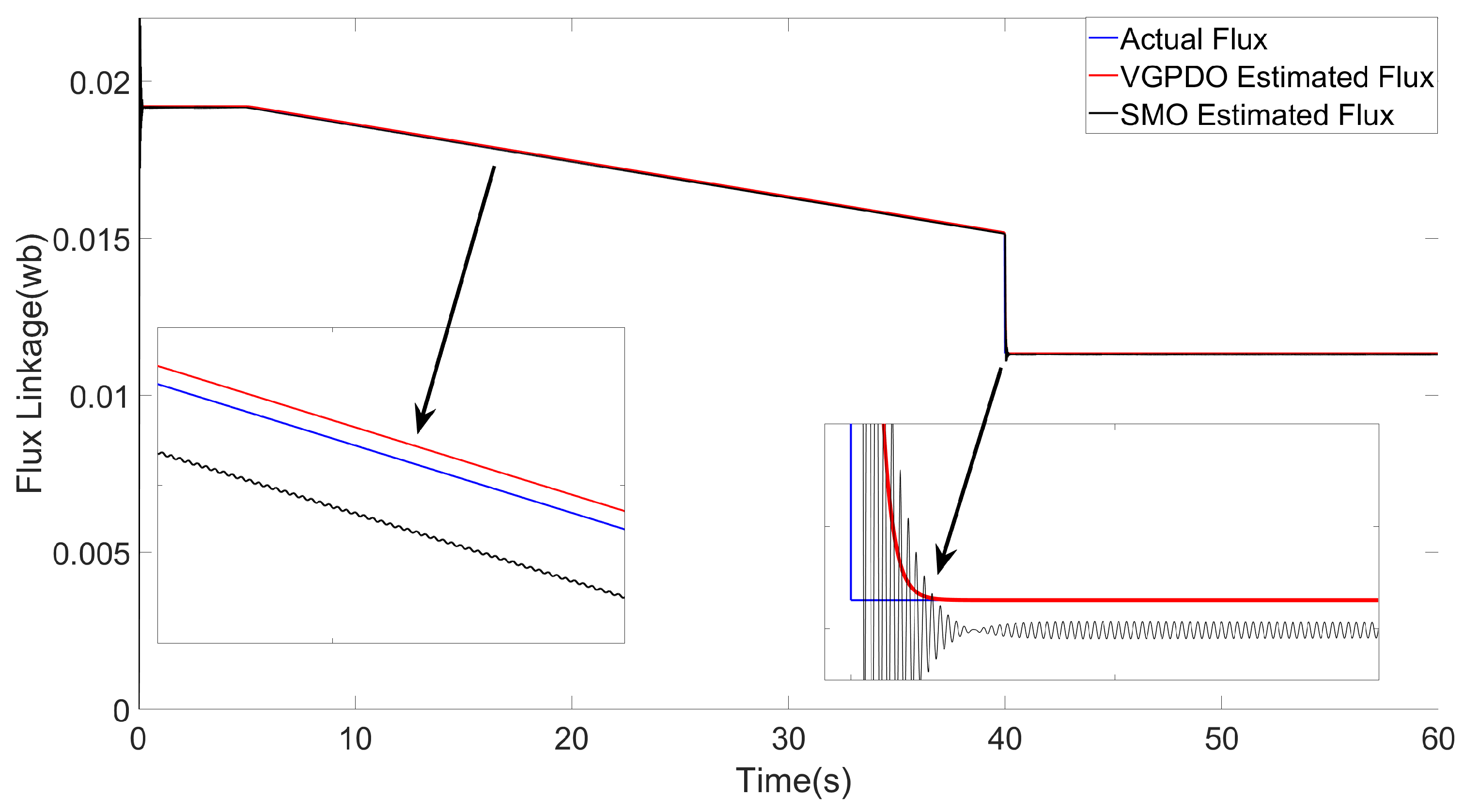
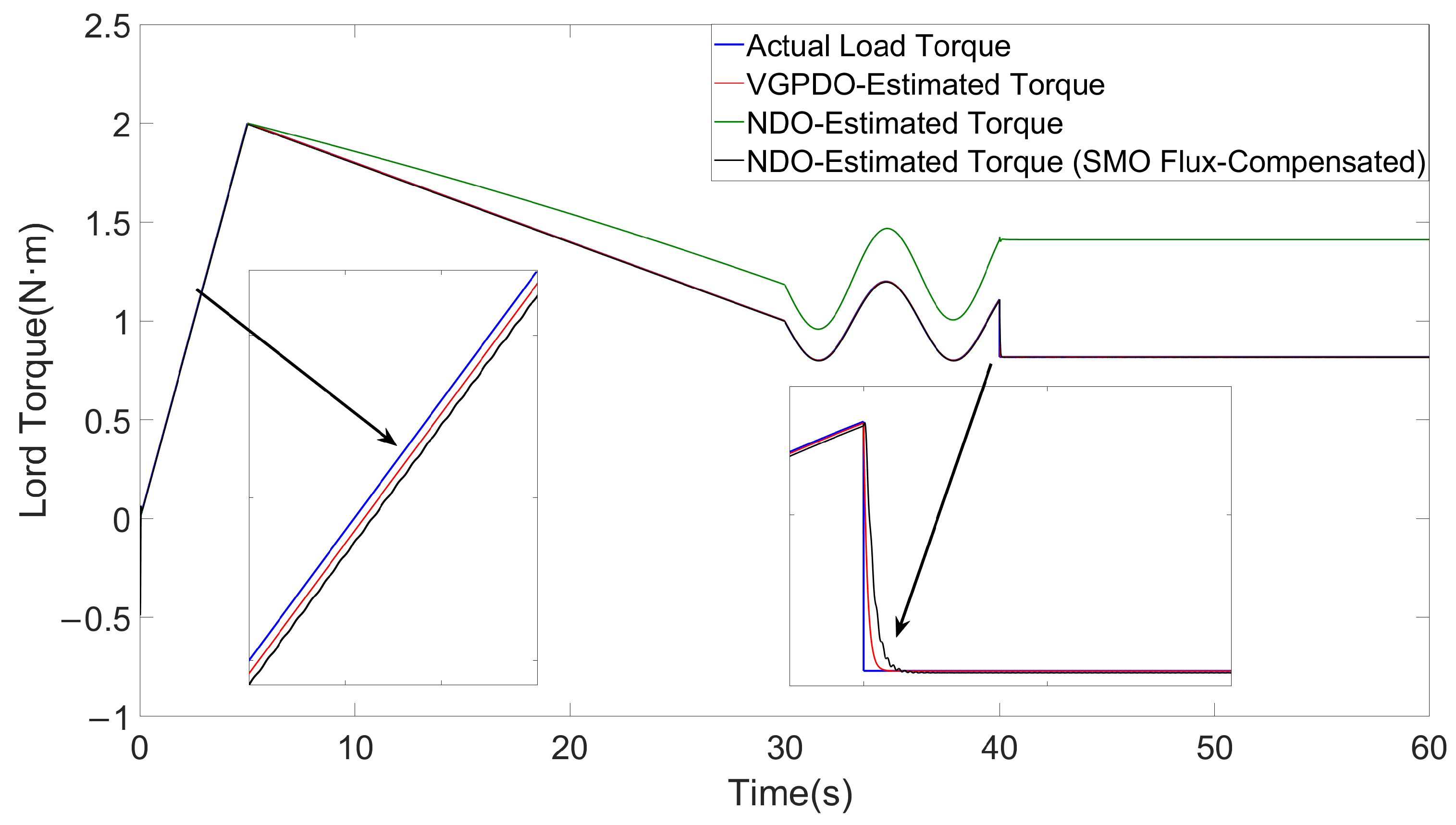
The load torque profile is configured as: (1) 0–5 s: linear ramp from 0 N·m to 2 N·m; (2) 5–30 s: linear decrease from 2 N·m to 1 N·m; (3) 30–40 s: sinusoidal oscillation (mean: 1 N·m, amplitude: 1 N·m, frequency: 2 π rad/s); (4) 40–60 s: constant torque at 1 N·m. The flux linkage variation includes three phases: (1) 0–2 s: maintained at initial value; (2) 2–40 s: decay at a rate of 0.6 % of ψ s per second; (3) 40–60 s: held constant. Additionally, an abrupt 20% flux linkage reduction is introduced at 40 s to emulate abrupt demagnetization under fault conditions. To intuitively demonstrate the performance of the proposed VGPDO algorithm, a simulation was first conducted under ideal, noise-free conditions, and the results are presented in Figure 2 and Figure 3.
The experimental results are presented in Figure 2 and Figure 3.
The flux linkage estimation results of the two observers are compared in Figure 2. During t = 0–40 s, the proposed VGPDO demonstrates superior dynamic tracking performance for flux estimation compared to the SMO proposed in [25], with no significant chattering phenomena observed. Following the abrupt flux linkage demagnetization event at t = 40 s, the SMO exhibits significant high-amplitude chattering in tracking. In contrast, VGPDO demonstrates smoother and more stable tracking performance. Ultimately, when both flux linkage and load torque stabilize after t = 40 s, VGPDO demonstrates a smooth transient response with rapid convergence, achieving asymptotic stability.
The torque estimation performance of different observers is shown in Figure 3. The NDO proposed in [25] achieves relatively accurate load torque estimation in the early period. However, with progressive deterioration of the flux linkage, the estimation error increases steadily, eventually causing complete observer failure. The SMO-compensated NDO achieves satisfactory load torque tracking but demonstrates persistent chattering, which intensifies dramatically under severe flux linkage degradation at t = 40 s, while the proposed VGPDO maintains smooth and stable tracking for the load torque all the time.
To further evaluate the performance of the proposed VGPDO algorithm and demonstrate its robustness against measurement noise, the simulation study was extended to include three distinct noise variance levels, building upon the initial noise-free results. A comparative summary of the performance metrics across all conditions is provided in Table 2.
Remark 3. 
The terms δ w 2 , δ i q 2 , and δ i d 2 denote the measurement noise variances for the angular velocity, q-axis current, and d-axis current, respectively; The maximum settling time is defined as the duration required for the observer’s estimation errors of both load torque and flux linkage to fall and remain below 2% after a step disturbance is applied to the PMSM at t = 40 s; The term "N/A" denotes a non-existing value. The CPU utilization was calculated in a SIL environment by converting the algorithm’s floating-point operation count into the equivalent execution time on a 180 MHz processor.
As shown in Table 2, under various noise conditions, the proposed VGPDO achieves smaller maximum estimation errors and lower RMSE for both load torque and flux, demonstrating better tracking accuracy. Meanwhile, the proposed VGPDO also exhibits a shorter maximum settling time, indicating a faster dynamic response.
Additionally, the proposed VGPDO algorithm demonstrates robustness to measurement noise, as evidenced by the minimal variation in its performance metrics across the first three different noise levels. Moreover, under different measurement noise variances, the CPU utilization of the proposed VGPDO algorithm showed minimal change. This suggests that the level of measurement noise has no strong correlation with its computational burden, and thus did not significantly increase the real-time computational demand.
To demonstrate the efficacy of the tuned parameters α 1 and α 2 in VGPDO, a sensitivity analysis was conducted under measurement noise variances of δ w 2 = 1 , δ i q = 10 3 and δ i d = 10 3 ; the results are summarized in Table 3.
As shown in Table 3, the parameters α 1 and α 2 exhibit an approximately linear inverse relationship with the settling time. When α 1 and α 2 are moderately increased from 10 to 100, the settling time of the VGPDO decreases significantly from 0.3921 s to 0.0403 s, indicating a substantial improvement in convergence speed and dynamic tracking performance. This trend is further corroborated by the monotonic decrease in the RMSE for both the load torque (from 1.520 × 10 2 to 2.986 × 10 3 ) and the flux linkage (from 1.116 × 10 3 to 3.590 × 10 4 ).
However, when α 1 = α 2 = 1000 , the maximum estimation error increases. This suggests that excessively large parameters degrade the algorithm’s filtering effectiveness against measurement noise, consequently reducing estimation accuracy.
Therefore, selecting α 1 , α 2 necessitates a trade-off between estimation accuracy and dynamic response speed. Systematic tuning is required to determine the optimal values for achieving the best overall performance of the VGPDO algorithm.
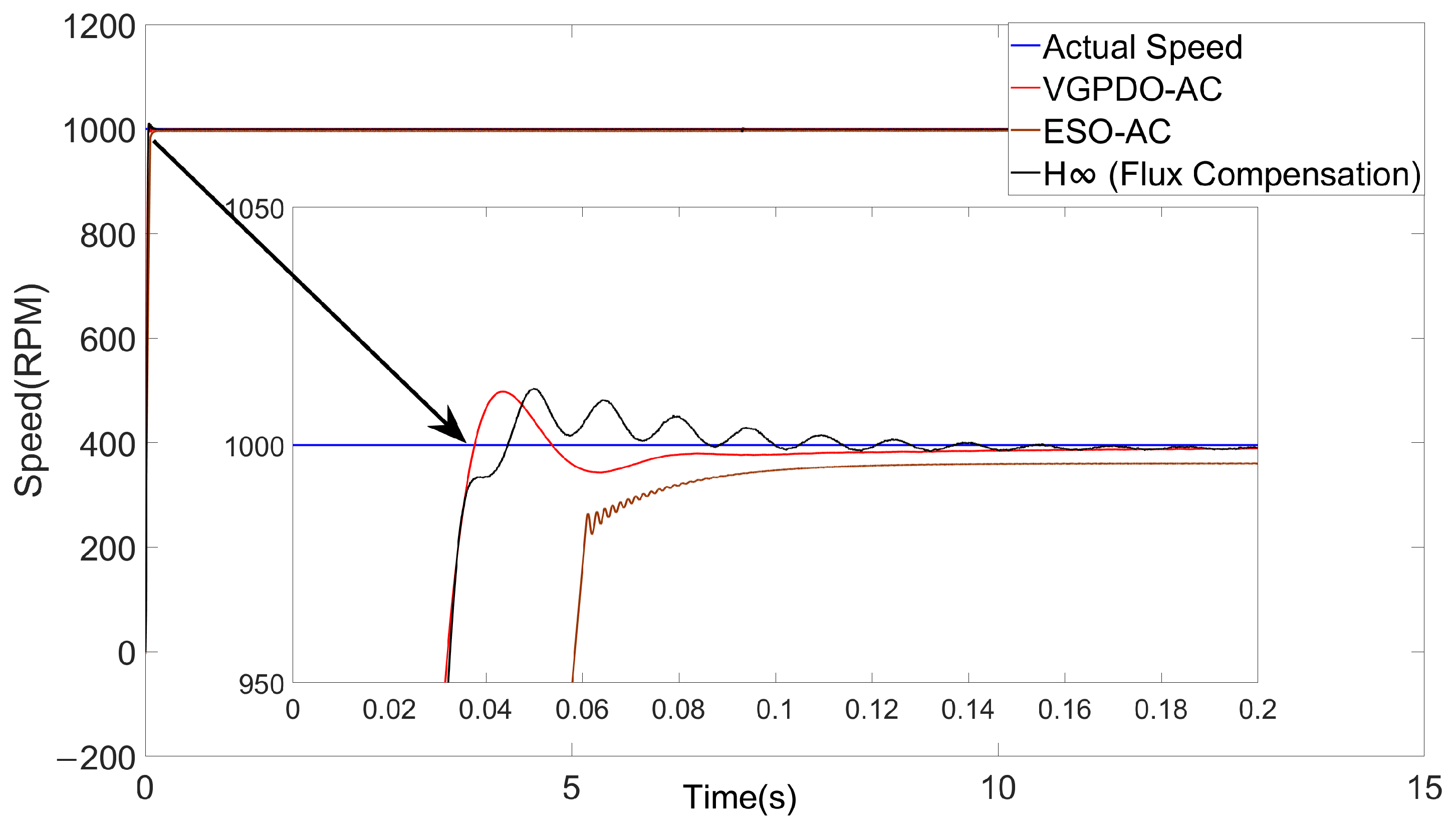
In simulation case 2, to validate the effectiveness of the proposed optimal robust control strategy integrating VGPDO and actor-critic neural network-based optimal speed controller (VGPDO-AC), we select the a set of optimal control strategy integrating a ESO and actor-critic neural network-based optimal speed controller (ESO-AC) from [18] as the benchmark. This comparative strategy employs ESO for system disturbance estimation and compensation, while utilizing actor-critic neural network to achieve the optimal control policy. Additionally, an H robust control algorithm that incorporates flux compensation is also adopted as a benchmark.
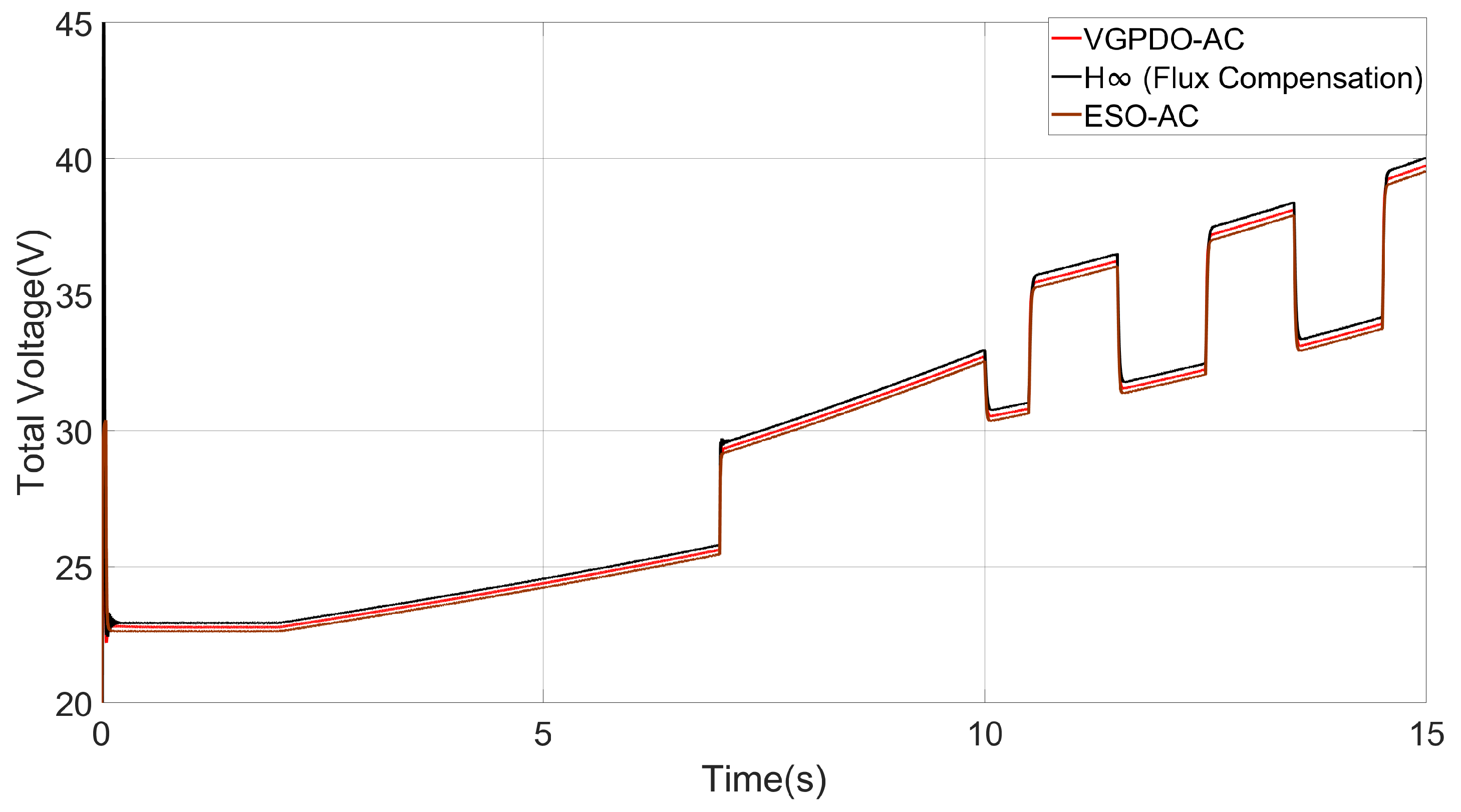
The load torque profile is configured as: (1) 0–2 s: constant at 1.5 N·m; (2) 2–10 s: linear increase from 1.5 N·m to 1.8 N·m; (3) 10–15 s: rectangular wave (mean: 1.8 N·m, amplitude: ±0.3 N·m, period: 2 s). The flux linkage variation includes: (1) 0–2 s: maintained at initial value ψ s ; (2) 2–15 s: decay at a rate of 2% of ψ s per second. Additionally, an abrupt 20% reduction is introduced at 7 s to emulate fault conditions. The PMSM reference speed ω d is set as a step command of 1000 RPM. The simulation is conducted with measurement noise variances of δ w 2 = 1 , δ i q = 10 3 , and δ i d = 10 3 .
For the actor-critic neural network, the weight matrix for state deviations is given by: Q = 100 0 0 0 100 0 0 0 100 . The weight matrix for input is given by: R = 0.5 0 0 1 . The basis functions are selected as: ζ x = x 1 x 2 x 2 x 3 x 1 x 3 x 1 2 x 2 2 x 3 2 T . The tunable parameter η c and η a is set to be 1 and 1, respectively.
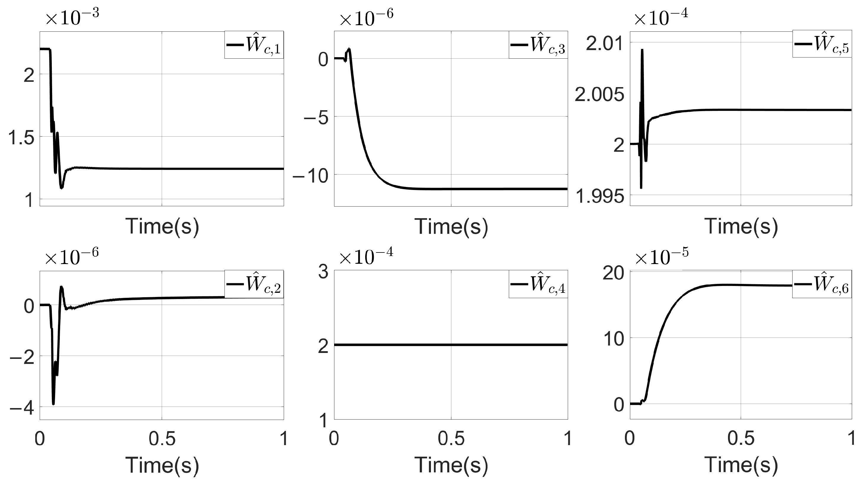
The simulation results are presented in Figure 4, Figure 5, Figure 6, Figure 7 and Figure 8. The relevant performance metrics from the experimental results can be found in Table 4.
As summarized in Table 4, the proposed VGPDO-AC strategy achieves the highest steady-state accuracy and fastest dynamic response, as evidenced by its smallest steady-state error (0.01217%), shortest settling time (0.0676 s), and minimum RMSE (27.3861) among all control strategies. Furthermore, it maintains lower power consumption ( 1.396 × 10 4 J) than the contemporary H-infinity control ( 1.424 × 10 4 J). Although its energy consumption is slightly higher than that of the ESO-AC strategy, the VGPDO-AC demonstrates notable overall control performance, positioning it as a high-performance and energy-efficient control solution.
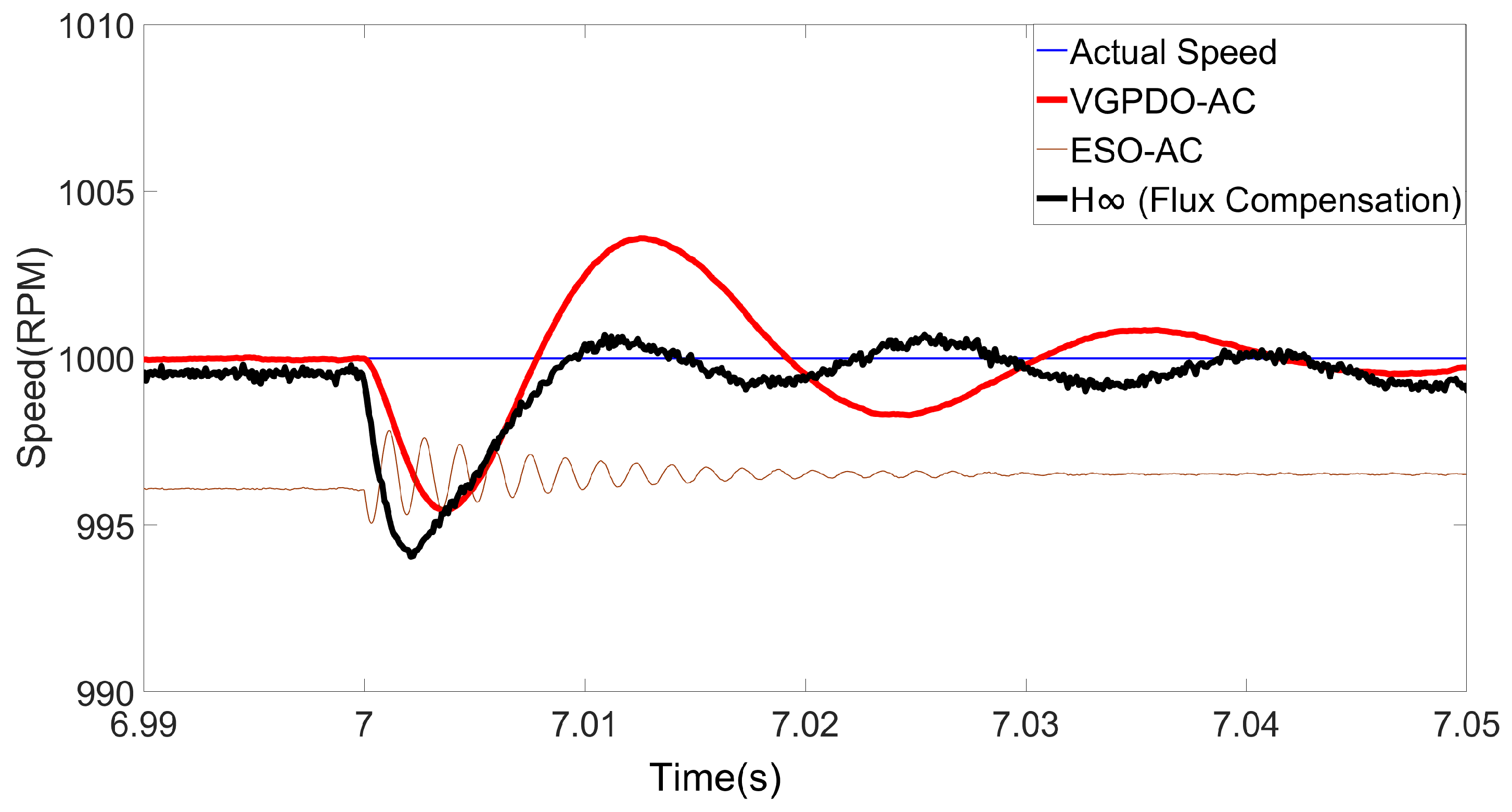
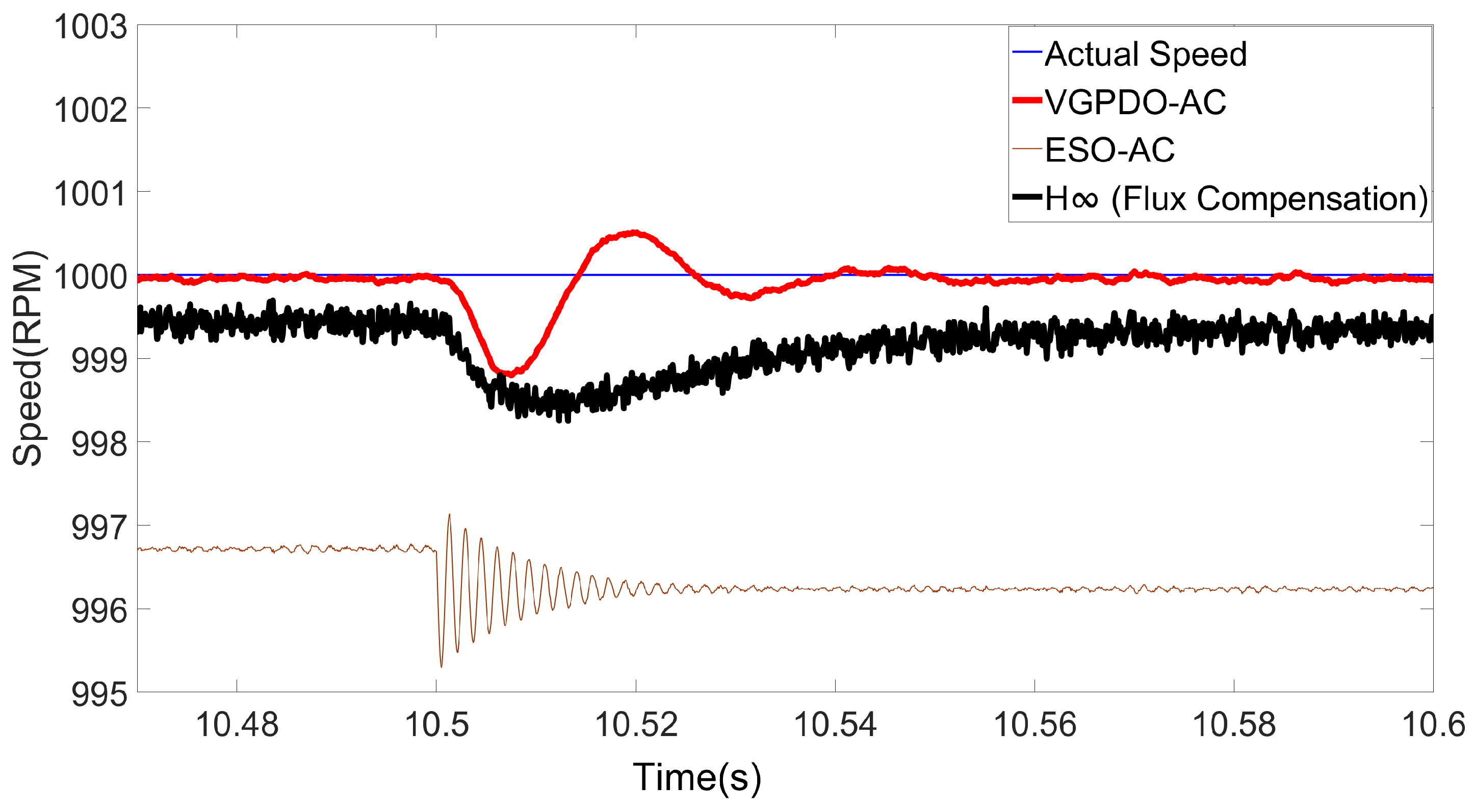
To demonstrate the robustness of the proposed VGPDO-AC control strategy, the dynamic speed responses of the PMSM under flux linkage and load torque step changes are illustrated in Figure 9 and Figure 10, respectively, with the corresponding performance metrics provided in Table 5 and Table 6.
As shown in Table 5 and Table 6, the proposed VGPDO-AC control strategy achieves both the lowest RMSE and the minimum maximum deviation under flux linkage and load torque disturbances. These results demonstrate that the proposed VGPDO-AC control strategy exhibits enhanced robustness against flux-weakening and abrupt load changes.
Based on the results from simulation case 2 under the step speed command scenario during the first second, a sensitivity analysis of the tunable parameters η a and η c is conducted in Table 7 and Table 8 to quantify their effects on key performance metrics.
Remark 4. 
  • The settling time of W ^ a is defined as the earliest time t s e t t l i n g such that for all t > t s e t t l i n g , we have: W ^ a ( t ) W ^ c ( t ) W ^ c ( t ) 2 %
  • The percentage deviation of W ^ a is used to evaluate its tracking performance relative to W ^ c and is computed as:
    max t t steady W ^ c ( t ) W ^ a ( t ) W ^ c ( t ) × 100 %
    where t steady denotes the time instant at which the system state enters the steady-state regime, and is is computed as twice the value of t settling .
  • The steady-state estimation error on V ^ ˙ ( x ) is used to evaluate the approximation degree of W ^ c to the actual cost function after W ^ c has converged, and is calculated as:
    max t t steady V ˙ ( x ( t ) ) V ^ ˙ ( x ( t ) ) V ˙ ( x ( t ) ) × 100 %
As shown in Table 8, the steady-state estimation error of V ^ ˙ ( x ) remains below 2% with no significant variation. This confirms that the critic neural network weight W ^ c in the proposed VGPDO-AC algorithm achieves an excellent approximation of the cost function V ( x ) . Furthermore, the CPU usage remains within the range of 50% to 60%, demonstrating the computational efficiency of the proposed algorithm. This indicates its potential for practical deployment on processors with 180 MHz clock frequencies at 5 kHz control rates.
Meanwhile, as shown in Table 7 and Table 8, as parameters η a and η c increase, the dynamic performance of both PMSM speed control and neural network weight updates is improved, evidenced by the monotonic decrease in the RMSE of the speed, the settling time of the speed, percentage deviation on W ^ a , settling time of W ^ a . This indicates that appropriately increasing η a and η c is beneficial for enhancing both the dynamic response rate of PMSM speed control and the convergence rate of W ^ a . However, this comes at the trade-off of an increase in the steady-state error of the speed. Therefore, the selection of η a and η c should be based on the specific control performance requirements.

6. Conclusions

In this paper, a VGPDO is proposed for PMSM that simultaneously estimates both flux linkage and load torque. Experimental results demonstrate that the VGPDO achieves smooth and rapid tracking of both flux linkage and load torque variations, while guaranteeing asymptotic stability when flux linkage and load torque reach steady-state conditions. Furthermore, we developed a robust optimal control framework that integrates the VGPDO estimates through feedforward compensation, which transforms the PMSM dynamics into an error dynamic system. Then we employ an actor-critic neural network to achieve optimal control. Experimental validation confirms that the proposed control strategy achieves optimal control while exhibiting superior dynamic tracking performance with minimal steady-state error and maintaining robustness against both flux-weakening operation and abrupt load torque variations.

Author Contributions

Conceptualization, Y.N.; methodology, Y.N.; software, Y.N.; validation, Y.N., H.S.; formal analysis, Y.N., H.S.; writing—original draft, Y.N.; writing—review and editing, Y.N.; supervision, Y.N. All authors have read and agreed to the published version of the manuscript.

Funding

This research received no funding.

Data Availability Statement

The original contributions presented in this study are included in the article. Further inquiries can be directed to the corresponding author.

Conflicts of Interest

The authors declare no conflicts of interest.

Abbreviations

The following abbreviations are used in this manuscript:
PMSMPermanent magnet synchronous motor
UUBUniform ultimate boundedness
ADPAdaptive dynamic programming
RLReinforcement learning
VGPDOVariable-gain proportional disturbance observer
ACactor-critic neural network

Appendix A

Appendix A.1

By substituting (18) into (15), we obtain:
T ˜ ˙ L = α 1 T ˜ L + T ˙ L Δ ψ ˜ ˙ = α 2 Δ ψ ˜ + Δ ψ ˙
Therefore, based on Assumption 1, the estimation error concerning flux linkage deterioration and disturbance torque can be derived as:
T ˜ L Υ 1 1 + α 1 2 Δ ψ ˜ Υ 2 1 + α 2 2
Notably, when the rate of change for both flux linkage and load torque becomes zero (i.e., T ˙ L = 0 and Δ ψ ˙ = 0 ), it follows from (A1) that T ˜ ˙ l and Δ ψ ˜ ˙ will achieve asymptotic stability.
Furthermore, the following expression can be derived:
m ˜ 1 m ^ 1 = Δ ψ ˜ ψ s + Δ ψ ^ + Δ ψ ˜ Υ 2 1 + α 2 2 ψ s + Υ 2 1 + α 2 2 = Υ 2 ψ s 1 + α 2 2 + Υ 2
Simultaneously, the following relationship holds:
m 2 ω d + m 3 T ^ L + ω ˙ d = m 2 ω d + m 3 T L + ω ˙ d m 3 T ˜ L m 2 γ 3 + m 3 γ 1 + Υ 3 m 3 Υ 1 1 + α 1 2
By combining inequality (A2)–(A4), with Assumption 1, the following can be obtained:
m 3 T ˜ L + m ˜ 1 m ^ 1 m 2 ω d + m 3 T ^ L + ω ˙ d δ 1
where:
δ 1 m 3 Υ 1 1 + α 1 2 2 + Υ 2 ψ s 1 + α 2 2 + Υ 2 ( m 2 γ 3 + m 3 γ 1 + Υ 3 m 3 Υ 1 1 + α 1 2 ) 2
From inequality (A2) and Assumption 1, it can be readily derived that:
m ˜ 5 w d γ 3 n p Δ ψ ˜ L n p γ 3 Υ 2 L 1 + α 2 2
Finally, by incorporating inequalities (A5) and (A7), we establish the boundary of δ as:
δ δ m
where:
δ m δ 1 2 + n p 2 γ 3 2 Υ 2 2 L 2 1 + α 2 2

Appendix A.2

Take (24) into (23), we have:
0 = Q ( x ) + V x T ( x ) f ( x ) 1 4 V x T ( x ) g ( x ) R 1 g T ( x ) V x ( x ) + V x T ( x ) δ
Take (27) into (A10), we have:
W c T ζ f 1 4 W c T ζ gR 1 g T ζ T W c + Q ( x ) = ε H J B
where ε H J B = ε T f + 1 2 W c T ζ gR 1 g T ε + 1 4 ε T g R 1 g T ε W c T ζ δ ε T δ . Take (36) and σ 1 = ζ ( f + g u ) into (A11) yield:
W c T σ 1 = Q ( x ) 1 4 W c T G ( x ) W c + ε H J B ( x )
The whole Lyapunov function is given by:
L = L V x + L c x + L a x = 1 2 x T x + 1 2 t r ( W ˜ c T a 1 1 W ˜ c ) + 1 2 t r ( W ˜ a T a 2 1 W ˜ a )
where we have: L V x 1 2 x T x , L c x 1 2 t r ( W ˜ c T a 1 1 W ˜ c ) , L a x 1 2 t r ( W ˜ a T a 2 1 W ˜ a ) .
The derivitive of L V is written as:
L ˙ V ( x ) = L V x · x ˙ = ζ T W c + ε · f ( x ) + g u 2 + δ = W c T ζ f ( x ) 1 2 G ( x ) W ^ a + ζ T W c + ε δ + ε T ( x ) f ( x ) 1 2 g ( x ) R 1 g T ( x ) ζ T W ^ a
To simplify the notation, let us define:
ε 1 ( x ) ε T ( x ) f ( x ) 1 2 g ( x ) R 1 g T ( x ) ζ T ( x ) W ^ a + ζ T W c + ε δ
The (A14) could be written as:
L ˙ V ( x ) = W c T ζ f ( x ) 1 2 G ( x ) W ^ a + ε 1 ( x ) = W c T ζ f ( x ) + 1 2 W c T G ( x ) W c W ^ a 1 2 W c T G ( x ) W c + ε 1 ( x ) = W c T ζ f ( x ) + 1 2 W c T G ( x ) W ˜ a 1 2 W c T G ( x ) W c + ε 1 ( x ) = W c T σ 1 + 1 2 W c T G ( x ) W ˜ a + ε 1 ( x )
Take (A12) into (A16) yields:
L ˙ V ( x ) = Q ( x ) 1 4 W c T G ( x ) W c + 1 2 W c T G ( x ) W ˜ a + ε H J B ( x ) + ε 1 ( x )
for L ˙ c , we have:
L ˙ c = W ˜ c T a 1 1 W ˜ ˙ c = W ˜ c T a 1 1 a 1 σ 2 σ 2 T σ 2 + 1 2 σ 2 T W ^ c + Q ( x ) + 1 4 W ^ a T G W ^ a
Rewriting (A12) gives:
0 = W c T σ 1 Q ( x ) 1 4 W c T G ( x ) W c + ε H J B ( x )
Taking Equation (A19) into Equation (A18) yields the following:
L ˙ c = W ˜ c T σ 2 σ 2 T σ 2 + 1 2 ( σ 2 T W ^ c + Q ( x ) + 1 4 W ^ a T G ( x ) W ^ a Q ( x ) σ 1 T W c 1 4 W c T G ( x ) W c + ε H J B ( x ) ) = W ˜ c T σ 2 σ 2 T σ 2 + 1 2 ( σ 2 T ( x ) W ^ c σ 1 T ( x ) W c + 1 4 W ^ a T G ( x ) W ^ a 1 4 W c T G ( x ) W c + ε H J B ( x ) )
Substituting (24) and (27) into σ 1 = ζ ( f + g u ) yields:
σ 1 = ζ ( f + g u ) = ζ f 1 2 g R 1 g W c T ζ + ε = ζ f 1 2 ζ g R 1 g W c T ζ x 1 2 ζ g R 1 g ε x
Take (A21), (37), (36) into σ 2 T ( x ) W ^ c σ 1 T ( x ) W c yields:
σ 2 T ( x ) W ^ c σ 1 T ( x ) W c = ζ ( f + g u 2 ) T W ^ c ζ ( f + g u ) T W c = ζ f W ˜ c + ζ g u 2 T W ^ c ζ g u T W c = ζ f W ˜ c + 1 2 ζ g R 1 g T ( x ) ζ T W ^ a T W ^ c ζ g u T W c = ζ f W ˜ c 1 2 W ^ a T G W ^ c W c T G W c + 1 2 ζ g R 1 g ε x T W c
Additionally, we can transform 1 2 W ^ a T G W ^ c 1 2 W c T G W c 1 4 W ^ a T G ( x ) W ^ a + 1 4 W c T G ( x ) W c as:
1 2 W ^ a T G W ^ c 1 2 W c T G W c 1 4 W ^ a T G ( x ) W ^ a + 1 4 W c T G ( x ) W c = 1 2 W ^ a T G W c W ˜ c 1 2 W c T G W c 1 4 W ^ a T G ( x ) W ^ a + 1 4 W c T G ( x ) W c = 1 2 W ^ a T G W ˜ c + 1 2 W ^ a T G W c 1 2 W c T G W c 1 4 W ^ a T G ( x ) W ^ a + 1 4 W c T G ( x ) W c = 1 2 W ^ a T G W ˜ + 1 2 W ^ a T G W c 1 4 W c T G W c 1 4 W ^ a T G ( x ) W ^ a = 1 2 W ^ a T G W ˜ 1 4 W ˜ a G W c + 1 4 W ^ a T G W ˜ a = 1 2 W ^ a T G W ˜ + 1 4 W ˜ a T G ( x ) W ˜ a
Substituting (A22) into (A20) and adding (A23) yields:
L ˙ c = W ˜ c T σ 2 σ 2 T σ 2 + 1 2 ( f ( x ) T ζ T ( x ) W ˜ c + 1 2 W ˜ a T G ( x ) W ˜ c + 1 4 W ˜ a T G ( x ) W ˜ a + ε H J B ( x ) 1 2 ζ g R 1 g ε T W c )
By combining Equations (34), (36) and (37), Equation (A24) can be reformulated as:
L ˙ c = W ˜ c T σ 2 σ 2 T σ 2 + 1 2 σ 2 T W ˜ c + 1 4 W ˜ a T G ( x ) W ˜ a + ε H J B ( x ) 1 2 ζ g R 1 g ε T W c
Substituting (A17), (A25) and (35) into the derivative of Equation (A13) yields:
L ˙ ( x ) = x T x ˙ + W ˜ c T a 1 1 W ˜ ˙ c + W ˜ a T a 2 1 W ˜ ˙ a = Q x 1 4 W c T G ( x ) W c + 1 2 W c T G ( x ) W ˜ a + ε H J B ( x ) + ε 1 ( x ) + W ˜ c T σ 2 σ 2 T σ 2 + 1 2 × σ 2 T W ˜ c + 1 4 W ˜ a T G ( x ) W ˜ a + ε H J B ( x ) 1 2 ζ g R 1 g ε T W c + W ˜ a T a 2 1 W ˜ ˙ a
Equation (A26) can be written as:
L ˙ ( x ) = L ¯ ˙ V + L ¯ ˙ c + ε 1 ( x ) W ˜ a T a 2 1 W ˜ ˙ a + 1 2 W ˜ a T G ( x ) W c + 1 4 W ˜ a T G ( x ) W c σ ¯ 2 T m s W ˜ c 1 4 W ˜ a T G ( x ) W c σ ¯ 2 T m s W c + 1 4 W ˜ a T G ( x ) W ˜ a σ ¯ 2 T m s W c + 1 4 W ˜ a T G ( x ) W ^ a σ ¯ 2 T m s W ^ c
with the definitions:
σ ¯ 2 σ 2 σ 2 T σ 2 + 1 m s σ 2 T σ 2 + 1 L ¯ ˙ V Q ( x ) 1 4 W c T G ( x ) W c + ε H J B ( x ) L ¯ ˙ c W ˜ c T σ 2 σ 2 T σ 2 + 1 2 σ 2 T W ˜ c + ε H J B ( x ) 1 2 ζ g R 1 g ε T W c
Taking (35) into (A27), we have the following:
L ˙ ( x ) = Q ( x ) 1 4 W c T G ( x ) W c + ε H J B ( x ) + W ˜ c T σ ¯ 2 σ ¯ 2 T W ˜ c + ε H J B ( x ) 1 2 ζ g R 1 g ε T W c m s + ε 1 ( x ) + 1 2 W ˜ a T G ( x ) W c + 1 4 W ˜ a T G ( x ) W c σ ¯ 2 T m s W ˜ c 1 4 W ˜ a T G ( x ) W c σ ¯ 2 T m s W c + 1 4 W ˜ a T G ( x ) W c σ ¯ 2 m s W ˜ a + W ˜ a T η a W c W ˜ a T η a W ˜ a W ˜ a T η c σ ¯ 2 T W c + W ˜ a T η c σ ¯ 2 T W ˜ c .
As established in [28], for any given γ ε , there exists N 0 such that ε H J B < γ ε holds when N > N 0 .
From Assumption 2 and (A15), it follows that:
ε 1 ( x ) < γ ε x γ f x + 1 2 γ ε x γ g 2 γ ζ x σ min 1 ( R ) W c + W ˜ a + γ g γ ζ x δ m
ζ g ε x T W c < γ ε γ g γ ζ x W c
where σ min 1 ( R ) denotes the reciprocal of the minimum singular value of matrix R.
Let ϵ be a positive definite constant satisfying the inequality: x T ϵ x < Q ( x ) and define Ω x σ ¯ 2 T W ˜ c W ˜ a , we obtain:
L ˙ < 1 4 W c 2 G ( x ) + γ ε + 1 2 W c γ ε x γ ζ x γ g 2 σ min 1 ( R ) + γ g γ ζ x δ m Ω T ϵ I 0 0 0 I 1 2 η c 1 8 m s G W c T 0 1 2 η c 1 8 m s G W c η a 1 8 G W c m T + m W c T G Ω + Ω T γ ε x γ f 2 γ ε + γ ε γ g 2 γ ζ x W c σ min 1 ( R ) 2 m s 1 2 G + η a η c σ ¯ 2 T 1 4 G W c m T W c + 1 2 γ ε x γ g 2 γ ζ x σ min 1 ( R )
Define:
H ϵ I 0 0 0 I 1 2 η c 1 8 m s G W c T 0 1 2 η c 1 8 m s G W c η a 1 8 G W c m T + m W c T G Γ γ ε x γ f 2 γ ε + γ ε γ g 2 γ ζ x W c σ min 1 ( R ) 2 m s 1 2 G + η a η c σ ¯ 2 T 1 4 G W c m T W c + 1 2 γ ε x γ g 2 γ ζ x σ min 1 ( R ) ρ 1 4 W c 2 G ( x ) + γ ε + 1 2 W c γ ε x γ ζ x γ g 2 σ min 1 ( R ) + γ g γ ζ x δ m
With proper selection of η c and η a guaranteeing H > 0 , the following holds:
L ˙ < Ω 2 σ min ( H ) + Γ Ω + ρ + γ ε
Based on (A34), we conclude that L ˙ is negative definite when:
Ω > Γ 2 σ min ( H ) + Γ 2 4 σ min 2 ( H ) + ρ + γ ε σ min ( H )
Thus, all signals in the closed-loop system are uniformly ultimately bounded.

References

  1. Wang, M.; Ren, X.; Chen, Q. Cascade Optimal Control for Tracking and Synchronization of a Multimotor Driving System. IEEE Trans. Control Syst. Technol. 2019, 27, 1376–1384. [Google Scholar] [CrossRef]
  2. Errouissi, R.; Al-Durra, A.; Muyeen, S.M. Experimental Validation of a Novel PI Speed Controller for AC Motor Drives with Improved Transient Performances. IEEE Trans. Control Syst. Technol. 2018, 26, 1414–1421. [Google Scholar] [CrossRef]
  3. Lee, H.; Lee, Y.; Shin, D.; Chung, C.C. H control based on LPV for load torque compensation of PMSM. In Proceedings of the 2015 15th International Conference on Control, Automation and Systems (ICCAS), Busan, Republic of Korea, 13–16 October 2015; pp. 1013–1018. [Google Scholar] [CrossRef]
  4. Zhang, X.; Sun, L.; Zhao, K.; Sun, L. Nonlinear Speed Control for PMSM System Using Sliding-Mode Control and Disturbance Compensation Techniques. IEEE Trans. Power Electron. 2013, 28, 1358–1365. [Google Scholar] [CrossRef]
  5. Repecho, V.; Biel, D.; Arias, A. Fixed Switching Period Discrete-Time Sliding Mode Current Control of a PMSM. IEEE Trans. Ind. Electron. 2018, 65, 2039–2048. [Google Scholar] [CrossRef]
  6. Linares-Flores, J.; García-Rodríguez, C.; Sira-Ramírez, H.; Ramírez-Cárdenas, O.D. Robust Backstepping Tracking Controller for Low-Speed PMSM Positioning System: Design, Analysis, and Implementation. IEEE Trans. Ind. Inform. 2015, 11, 1130–1141. [Google Scholar] [CrossRef]
  7. Yin, W.; Wu, X.; Rui, X. Adaptive Robust Backstepping Control of the Speed Regulating Differential Mechanism for Wind Turbines. IEEE Trans. Sustain. Energy 2019, 10, 1311–1318. [Google Scholar] [CrossRef]
  8. Li, S.; Zhou, M.; Yu, X. Design and Implementation of Terminal Sliding Mode Control Method for PMSM Speed Regulation System. IEEE Trans. Ind. Inform. 2013, 9, 1879–1891. [Google Scholar] [CrossRef]
  9. Preindl, M.; Bolognani, S. Model Predictive Direct Speed Control with Finite Control Set of PMSM Drive Systems. IEEE Trans. Power Electron. 2013, 28, 1007–1015. [Google Scholar] [CrossRef]
  10. Li, S.; Ding, L.; Gao, H.; Liu, Y.J.; Huang, L.; Deng, Z. ADP-Based Online Tracking Control of Partially Uncertain Time-Delayed Nonlinear System and Application to Wheeled Mobile Robots. IEEE Trans. Cybern. 2020, 50, 3182–3194. [Google Scholar] [CrossRef]
  11. Xue, S.; Zhao, N.; Zhang, W.; Luo, B.; Liu, D. A Hybrid Adaptive Dynamic Programming for Optimal Tracking Control of USVs. IEEE Trans. Neural Netw. Learn. Syst. 2025, 36, 9961–9969. [Google Scholar] [CrossRef] [PubMed]
  12. Yu, Y.; Ma, X.; Su, R.; Jet, T.K.; Viswanathan, V.; Gajanayake, C.J.; RamaKrishna, S.; Gupta, A.K. Application of integral reinforcement learning for optimal control of a high speed flux-switching permanent magnet machine. In Proceedings of the IECON 2016-42nd Annual Conference of the IEEE Industrial Electronics Society, Florence, Italy, 23–26 October 2016; pp. 2702–2707. [Google Scholar] [CrossRef]
  13. Chen, G.; Wang, W.; Dong, J. Performance-Optimize Adaptive Robust Tracking Control for USV-UAV Heterogeneous Systems with Uncertainty. IEEE Trans. Veh. Technol. 2025, 74, 7251–7262. [Google Scholar] [CrossRef]
  14. Chen, G.; Dong, J. Approximate Optimal Adaptive Prescribed Performance Control for Uncertain Nonlinear Systems with Feature Information. IEEE Trans. Syst. Man Cybern. Syst. 2024, 54, 2298–2308. [Google Scholar] [CrossRef]
  15. Jiang, Y.; Jiang, Z.P. Robust Adaptive Dynamic Programming with an Application to Power Systems. IEEE Trans. Neural Netw. Learn. Syst. 2013, 24, 1150–1156. [Google Scholar] [CrossRef]
  16. Heydari, A. Optimal Impulsive Control Using Adaptive Dynamic Programming and its Application in Spacecraft Rendezvous. IEEE Trans. Neural Netw. Learn. Syst. 2021, 32, 4544–4552. [Google Scholar] [CrossRef]
  17. El-Sousy, F.F.M.; Amin, M.M.; Al-Durra, A. Adaptive Optimal Tracking Control Via Actor-Critic-Identifier Based Adaptive Dynamic Programming for Permanent-Magnet Synchronous Motor Drive System. IEEE Trans. Ind. Appl. 2021, 57, 6577–6591. [Google Scholar] [CrossRef]
  18. Lee, J.; You, S.; Kim, W.; Moon, J. Extended state observer-actor–critic architecture based output-feedback optimized backstepping control for permanent magnet synchronous motors. Expert Syst. Appl. 2025, 270, 126542. [Google Scholar] [CrossRef]
  19. Fan, Z.X.; Li, S.; Liu, R. ADP-Based Optimal Control for Systems with Mismatched Disturbances: A PMSM Application. IEEE Trans. Circuits Syst. II Express Briefs 2023, 70, 2057–2061. [Google Scholar] [CrossRef]
  20. Fan, Z.X.; Li, S.; Su, J. Adaptive Dynamic Programming for PMSM Control Under Safety, Robustness, and Optimality Constraints. IEEE Trans. Syst. Man Cybern. Syst. 2025, 55, 2724–2733. [Google Scholar] [CrossRef]
  21. Wang, Z.; Ye, H.; Wang, Y.; Shi, Y.; Liang, L. Optimal Output-Feedback Controller Design Using Adaptive Dynamic Programming: A Permanent Magnet Synchronous Motor Application. IEEE Trans. Circuits Syst. II Express Briefs 2025, 72, 208–212. [Google Scholar] [CrossRef]
  22. Vamvoudakis, K.G.; Lewis, F.L. Online actor–critic algorithm to solve the continuous-time infinite horizon optimal control problem. Automatica 2010, 46, 878–888. [Google Scholar] [CrossRef]
  23. Uddin, M.N.; Zou, H.; Azevedo, F. Online Loss-Minimization-Based Adaptive Flux Observer for Direct Torque and Flux Control of PMSM Drive. IEEE Trans. Ind. Appl. 2016, 52, 425–431. [Google Scholar] [CrossRef]
  24. Ye, S.; Yao, X. A Modified Flux Sliding-Mode Observer for the Sensorless Control of PMSMs with Online Stator Resistance and Inductance Estimation. IEEE Trans. Power Electron. 2020, 35, 8652–8662. [Google Scholar] [CrossRef]
  25. Podder, A.; Pandit, D. Study of Sensorless Field-Oriented Control of SPMSM Using Rotor Flux Observer & Disturbance Observer Based Discrete Sliding Mode Observer. In Proceedings of the 2021 IEEE 22nd Workshop on Control and Modelling of Power Electronics (COMPEL), Cartagena, Colombia, 2–5 November 2021; pp. 1–8. [Google Scholar] [CrossRef]
  26. Zhu, G.; Dessaint, L.A.; Akhrif, O.; Kaddouri, A. Speed tracking control of a permanent-magnet synchronous motor with state and load torque observer. IEEE Trans. Ind. Electron. 2000, 47, 346–355. [Google Scholar] [CrossRef]
  27. Apte, A.; Joshi, V.A.; Mehta, H.; Walambe, R. Disturbance-Observer-Based Sensorless Control of PMSM Using Integral State Feedback Controller. IEEE Trans. Power Electron. 2020, 35, 6082–6090. [Google Scholar] [CrossRef]
  28. Hornik, K.; Stinchcombe, M.; White, H. Universal approximation of an unknown mapping and its derivatives using multilayer feedforward networks. Neural Netw. 1990, 3, 551–560. [Google Scholar] [CrossRef]
  29. Li, J.; Liu, H.; Zhang, Z.; Li, X.; Yang, X. Event-triggered adaptive NN tracking control with dynamic gain for a class of unknown nonlinear systems. Neurocomputing 2022, 467, 292–299. [Google Scholar] [CrossRef]
  30. Abu-Khalaf, M.; Lewis, F.L. Nearly optimal control laws for nonlinear systems with saturating actuators using a neural network HJB approach. Automatica 2005, 41, 779–791. [Google Scholar] [CrossRef]
  31. Modares, H.; Lewis, F.L. Optimal tracking control of nonlinear partially-unknown constrained-input systems using integral reinforcement learning. Automatica 2014, 50, 1780–1792. [Google Scholar] [CrossRef]
  32. Li, D.; Dong, J. Approximate Optimal Robust Tracking Control Based on State Error and Derivative Without Initial Admissible Input. IEEE Trans. Syst. Man Cybern. Syst. 2024, 54, 1059–1069. [Google Scholar] [CrossRef]
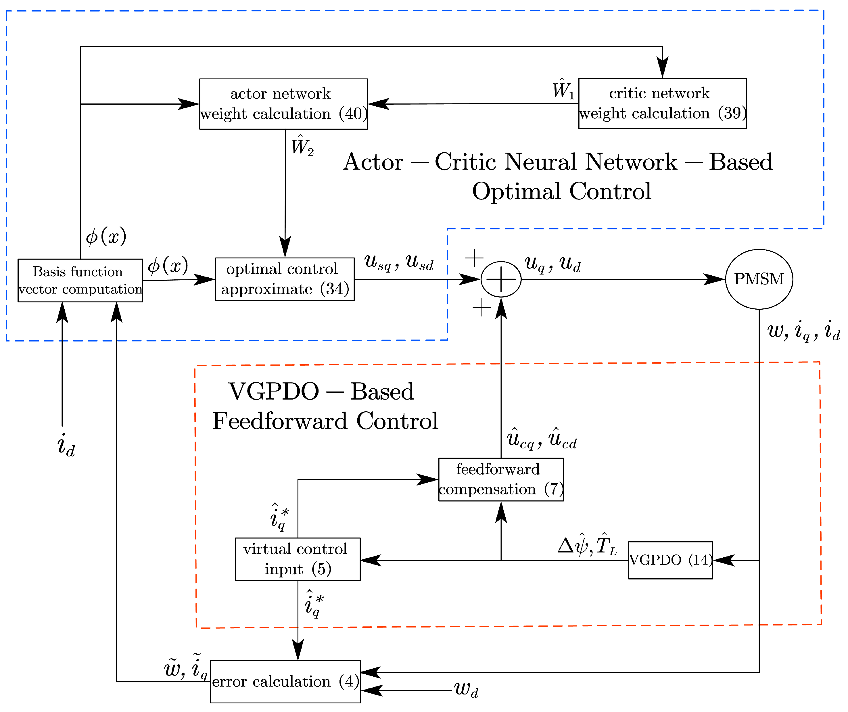
Figure 1. Flowchart of the robust optimal control strategy based on VGPDO and actor-critic neural network.
Mathematics 13 03387 g001
Figure 2. Flux linkage estimation results achieved by VGPDO and SMO.
Mathematics 13 03387 g002
Figure 3. Torque estimation results achieved by VGPDO and SMO.
Mathematics 13 03387 g003
Figure 4. Speed trajectories under three strategy.
Mathematics 13 03387 g004
Figure 5. Total voltage under three strategy.
Mathematics 13 03387 g005
Figure 6. Critic NN weight update trajectory on VGPDO-AC.
Mathematics 13 03387 g006
Figure 7. Actor NN weight update trajectory on VGPDO-AC.
Mathematics 13 03387 g007
Figure 8. V ˙ ( x ) and V ^ ˙ ( x ) trajectory on VGPDO-AC.
Mathematics 13 03387 g008
Figure 9. Speed trajectories for three strategies under flux linkage step disturbance.
Mathematics 13 03387 g009
Figure 10. Speed trajectories for three strategies under load torque step disturbance.
Mathematics 13 03387 g010
Table 1. Parameters of PMSM.
SymbolsValuesSymbolsValues
U R 60 V n p 4
I R 12 A ψ s 0.0192 Wb
J 7.06 × 10 4 kg · m 2 R s 0.72 Ω
B 3.5 × 10 4 N · s / rad L 0.4 × 10 3 H
Table 2. Performance comparison of VGPDO and NDOB-SMO algorithms under different measurement noise variance conditions.
AlgorithmNoise Variance
( δ w , δ iq 2 , δ id 2 )
Maximum Estimation Error (%) RMSEMaximum
Setting Time (s)
CPU Usage (%)
Load Torque Flux Linkage Load Torque Flux Linkage
VGPDO ( 0 , 0 , 0 ) 0.33310.0755 2.961 × 10 3 5.074 × 10 5 0.078212.26
( 1 , 10 3 , 10 3 ) 0.39640.1525 2.986 × 10 3 5.083 × 10 5 0.080113.98
( 10 , 10 2 , 10 2 ) 0.61650.2469 3.271 × 10 3 5.175 × 10 5 0.085714.24
( 100 , 0.5 , 0.5 ) 3.6013.109 1.176 × 10 2 1.263 × 10 4 N/A13.17
NDOB-SMO ( 0 , 0 , 0 ) 0.71760.3496 1.148 × 10 2 3.358 × 10 4 0.132811.6
( 1 , 10 3 , 10 3 ) 2.9960.5022 1.251 × 10 2 3.590 × 10 4 0.133115.74
( 10 , 10 2 , 10 2 ) 3.3650.9817 1.955 × 10 2 3.608 × 10 4 0.134515.96
( 100 , 0.5 , 0.5 ) 7.9575.422 2.271 × 10 2 4.244 × 10 4 N/A14.2
Table 3. Sensitivity analysis of α 1 , α 2 on VGPDO performance.
α 1 α 2 Maximum Estimation Error (%)RMSEMaximum
Setting Time (s)
CPU Usage (%)
Load Torque Flux Linkage Load Torque Flux Linkage
10103.3060.12651.520 × 10 2 1.116 × 10 3 0.392111.63
30301.1160.11836.470 × 10 3 6.424 × 10 4 0.130815.74
50500.68420.15254.563 × 10 3 4.987 × 10 4 0.080115.96
1001000.39650.22062.986 × 10 3 3.590 × 10 4 0.040314.20
100010000.64710.80101.791 × 10 3 2.782 × 10 4 N/A12.96
Table 4. Speed control performance evaluated for three strategies under comprehensive operating conditions.
Control StrategySteady-State
Error (%)
RMSEEnergy
Consumption (J)
Settling
Time (s)
H - Flux Compensation0.0833132.84251.424 × 10 4 0.0814
ESO-AC0.3935934.43451.387 × 10 4 0.1044
VGPDO-AC0.0121727.38611.396 × 10 4 0.0676
Table 5. Speed control performance evaluated for three strategies under flux linkage step disturbance.
AlgorithmMaximum Deviation (%)RMSE
H - Flux Compensation0.59570.6515
ESO-AC0.4953.4886
VGPDO-AC0.46230.3582
Table 6. Speed control performance evaluated for three strategies under load torque step disturbance.
AlgorithmMaximum Deviation (%)RMSE
H - Flux Compensation0.17470.6947
ESO-AC0.38163.7403
VGPDO-AC0.11560.1034
Table 7. Sensitivity analysis of η a , η c on PMSM speed control.
η a η c Speed
RMSE Steady-State Error (%) Settling Time (s)
0.10.1100.200.009720.1004
0.50.596.990.010580.0874
1192.210.012170.0689
2290.870.02260.0443
Table 8. Sensitivity analysis of η a , η c on NN network update performance of VGPDO-AC algorithm.
η a η c W ^ a Steady-State Estimation
Error on V ^ ˙ ( x ) (%)
CPU Usage (%)
Percentage Deviation (%) Settling Time (s)
0.10.10.53070.63291.68460.329
0.50.50.33030.30481.65359.484
110.10500.20661.64056.649
220.01290.16091.80752.418
Disclaimer/Publisher’s Note: The statements, opinions and data contained in all publications are solely those of the individual author(s) and contributor(s) and not of MDPI and/or the editor(s). MDPI and/or the editor(s) disclaim responsibility for any injury to people or property resulting from any ideas, methods, instructions or products referred to in the content.