Article

Environmental Disturbance Effects on Liquid Crystal Elastomer Photothermal-Oscillator Dynamics

School of Civil Engineering, Anhui Jianzhu University, Hefei 230601, China
*
Author to whom correspondence should be addressed.
Mathematics 2025, 13(21), 3365; https://doi.org/10.3390/math13213365
Submission received: 23 September 2025 / Revised: 15 October 2025 / Accepted: 16 October 2025 / Published: 22 October 2025
(This article belongs to the Special Issue New Advances in Nonlinear Dynamics Theory and Applications)

Abstract

Self-oscillations convert ambient energy into continuous periodic motion through feedback mechanisms, but their response to external periodic disturbances is not yet fully understood. Through the combination of a photothermally-responsive liquid crystal elastomer fiber and a mass block within a linear light field, we consider a liquid crystal elastomer self-oscillator. Following theoretical modeling of the light-driven self-oscillator under external periodic forcing and numerical simulations, three distinct phase-locking regimes are identified: in-phase, anti-phase, and quadrature synchronizations. Mechanisms are elucidated through time-domain, frequency-domain, and phase-space analyses. Moreover, approximate analytical expressions for the steady-state amplitude–frequency and phase–frequency responses of the self-oscillator under periodic forcing are derived using the multi-scale method. The impact of periodic forcing on the self-oscillator and its response regulation via system parameters is examined. A close correspondence exists between numerical and analytical results. This work investigates the response characteristics of a liquid crystal elastomer self-oscillator under periodic forcing, advances fundamental insights into disturbance rejection in self-oscillators, and delivers practical guidance for their robust operation in complex oscillatory settings.

1. Introduction

Self-oscillation, an autonomously energy-sustained dynamic phenomenon, pervades both natural and engineering systems [1,2,3]. It can convert ambient energy into continuous periodic motion, circumventing the need for additional complex controllers or portable batteries [4,5]. Crucially, the inherent self-regulating nature and robustness [6,7] render self-oscillation highly attractive for deployment in soft robotics [8,9,10], energy-absorbing devices [11], biomimetic engineering [12], and mass transport devices [13,14].
The advent of stimuli-responsive materials has opened new pathways for engineering self-oscillators. Hydrogels [15,16,17,18], ionic gels [19,20,21], dielectric elastomers [22], and liquid crystal elastomers (LCEs) [23,24,25,26,27,28,29] are typical stimuli-responsive materials, exhibiting multifunctional actuation. Studies have confirmed multiple motion patterns, ranging from rolling [30], jumping [31,32], swing [33,34,35], swimming [36], bending [37,38], buckling [39,40], vibration [41,42,43], crawling [44], twisting [45,46,47], chaos [48,49], to synchronized motion in coupled self-oscillators [50,51]. Their defining attributes are manifested through several feedback mechanisms, such as self-shadowing [39,40], the coupling of large deformation and chemical reaction [19,20], and the interaction of liquid volatilization with membrane deformation [3].
LCEs have emerged as optimal materials for constructing self-oscillators. Through integrating anisotropic liquid crystal molecules and stretchable long chains, LCEs achieve functional convergence between rubber-like elasticity and liquid crystalline anisotropy [52,53,54]. Upon exposure to external stimuli, encompassing optical [55,56,57,58,59], thermal [60,61,62,63,64], magnetic [65], or electric [66,67,68,69] fields, mesogen reorientation triggers macroscopic shape morphing. In particular, optical excitation constitutes a prominent stimulus modality, owing to its eco-friendliness, contactless control, and programmability [70,71]. These benefits have driven the continuous refinement of the light-powered self-oscillators architected from LCEs, with the effectiveness validated in prior studies [72,73,74,75,76,77,78].
Previous studies have largely focused on the isolated self-oscillatory behavior. However, idealized models and laboratory performance often differ significantly from complex real-world applications. In practice settings, the self-oscillators inevitably encounter environmental perturbations [79,80], i.e., mechanical load fluctuations, or ambient vibrational noise. These typically manifest as persistent periodic or quasi-periodic forces acting directly on the oscillator or its supports. This interplay between intrinsic self-oscillation and external periodic forcing can give rise to rich nonlinear phenomena, including synchronization, quasi-periodicity, or even chaotic behavior. External periodic forcing can enhance oscillatory coherence in dynamical systems. A notable example is found in biomedical engineering, where cardiac pacemakers deliver precisely timed electrical impulses to synchronize and stabilize the heart’s intrinsic rhythms, thereby improving both regularity and robustness. Furthermore, such external periodic forcing can also reconfigure oscillatory patterns. In soft robotics, for instance, external acoustic signals are used to induce gait transitions, allowing for adaptive locomotion in response to varying operational demands. Conversely, unintended periodic disturbances may also degrade performance, leading to frequency drift, amplitude modulation, or phase instability. Thus, characterizing how external periodic forcing affects key attributes of the self-oscillator, such as frequency, amplitude, and phase, is fundamental for designing high-performance self-oscillators with enhanced reliability and environmental immunity.
At present, numerical approaches are commonly used to analyze self-oscillation, yet they are restricted by substantial resource consumption and prolonged computation time. However, extracting analytical solutions for the governing equations can deliver vital mathematical understanding. Frequently employed analytical approaches include the averaging method, the multi-scale method [81,82], the asymptotic method [83], the harmonic balance method [84,85], and the perturbation method [86,87]. Among these, the multi-scale method distinguishes itself through its superior accuracy, simplicity in operation, and broad applicability. In the current work, we model an LCE self-oscillator comprising a photothermally-responsive LCE fiber and a mass block within a linear light field. Building upon the photothermally-responsive LCE model, we formulate a theoretical model for the light-driven LCE self-oscillator under external periodic forcing. Combining the numerical simulation and multi-scale method, we systematically probe how external periodic forcing influences the core attributes of the LCE self-oscillator, i.e., amplitude, frequency, and phase. The response regulation of the LCE self-oscillator via system parameters is also investigated. This work may advance fundamental insights into the disturbance rejection of the LCE self-oscillators and deliver practical guidance for their robust operation in complex oscillatory settings.
The structure of this paper is as follows. Section 2 presents the theoretical model of a light-driven LCE self-oscillator under external periodic forcing, the governing equations incorporating the photothermally-responsive LCE model, and the dimensionless treatment of the equations. Section 3 explores the phase-locking regimes and the underlying mechanisms. In Section 4, we employ the multi-scale method to obtain the steady-state amplitude–frequency and phase–frequency responses of the LCE self-oscillator under periodic forcing. Section 5 utilizes numerical and analytical approaches to comparatively examine the effect of periodic forcing on the response of the LCE self-oscillator. Section 6 investigates how system parameters regulate the response of the LCE self-oscillator under periodic forcing. Finally, the conclusions are given in Section 7.

2. Theoretical Model and Formulation

In this section, we first develop the theoretical model for a light-driven LCE self-oscillator under external periodic forcing. Then, incorporating the photothermally-responsive LCE model, we derive the governing equation for the LCE self-oscillator under periodic forcing. Finally, the equation undergoes nondimensionalization, and its asymptotic expression is derived for analysis.

2.1. Theoretical Model and Dynamics

Figure 1 illustrates the theoretical model of a light-driven LCE self-oscillator under external periodic forcing. The LCE self-oscillator comprises a photothermally-responsive LCE fiber with an original length of L and a mass block with a mass of m , as presented in Figure 1a. Attributed to the coupled effect of gravity and photothermally-driven contraction deformation of the LCE fiber, the system generates self-oscillations within a linear light field, as described in Figure 1b. Here, the mass block moves up and down, with its displacement being w ( t ) . Widely recognized, the LCE self-oscillator undergoes a periodic self-sustained vibration at its natural frequency [88,89]. After entering the steady state, an external periodic forcing F e ( t ) is applied to the LCE self-oscillator, as shown in Figure 1c. Given the force analysis in Figure 1d, the mass block experiences the tensile force F f ( t ) from the LCE fiber, the damping force F d ( w ˙ ) , gravity m g , and external periodic forcing F e ( t ) . Hence, the dynamic governing equation yields the following:
m w ¨ ( t ) + F f ( t ) + F d ( w ˙ ) m g F e ( t ) = 0 ,
where w ˙ ( t ) and w ¨ ( t ) refer to the velocity and acceleration of the mass block, respectively; the damping force is F d ( w ˙ ) = ( β 1 + β 2 w ˙ ) w ˙ with β 1 and β 2 being the first and second damping coefficients, respectively; g is the gravitational acceleration; and the external periodic forcing can be described as F e ( t ) = F e cos ω t , with F e and ω being the forcing amplitude and angular frequency, respectively.

2.2. Tensile Force Incorporating LCE Model

Employing two coordinate systems allows for a better description of the self-oscillation and the tensile force F f ( t ) of the LCE fiber in the linear light field. As depicted in Figure 1a,b, the coordinate X denotes the position of an arbitrary point on the LCE fiber in the reference state, and x ( X , t ) and u ( X , t ) represent the instantaneous position and displacement of the point on the LCE fiber in the current state, respectively. Evidently, we have x ( X , t ) = u ( X , t ) + X .
Considering a linear elastic model with tension proportional to deformation, we derive the following:
F f ( t ) = K f L ε e ( X , t ) = K f L ε t o t X , t ε T X , t ,
where K f denotes the elastic coefficient of the LCE fiber, and ε e ( X , t ) represents the elastic strain calculated from the linear combination of total strain ε t o t ( X , t ) = u ( X , t ) X and photothermally-driven contraction strain ε T ( X , t ) . Notably, the elastic coefficient K f of the LCE fiber is temperature-dependent, typically decreasing initially with temperature before stabilizing within a certain range [90]. For model simplicity, however, K f is treated as constant.
Moreover, ε T ( X , t ) originates from the temperature change within the linear light field, usually nonlinear with temperature. The core physics we aim to capture is the coupling between the photothermally-induced deformation and the resulting motion that triggers self-oscillation. The linear model for small deformations provides a physically sound and theoretically robust foundation. Hence, we assume that ε T ( X , t ) changes linearly with temperature, i.e.,
ε T ( X , t ) = α T ( X , t ) ,
where α is the thermal expansion coefficient governing the contraction or expansion of the LCE fiber. A negative α < 0 denotes thermal contraction, while a positive α > 0 represents thermal expansion.
Substituting Equation (3) into Equation (2), and then integrating both sides simultaneously yields the following:
F f ( t ) X = K f L u X , t α 0 x T X , t d X .
For simplicity, the tensile force within the LCE fiber is treated as spatially uniform, justified by the assumption of a quasi-static mechanical state; thus, the tensile force at X = L is as follows:
F f ( t ) = K f w ( t ) α 0 L T X , t d X .
Due to the non-uniform temperature distribution and its time variation in the LCE fiber, heat exchanges with the environment. To determine this temperature difference, we introduce two key assumptions: firstly, the radius of the thin fiber is much smaller than its length, justifying a uniform temperature profile across its cross-section; secondly, the surrounding temperature maintains a constant spatial gradient. Hence, the temperature distribution T = T ( X , t ) in the LCE fiber becomes uniform, governed by the following:
ρ C d T ( X , t ) d t     =   q ext ( x )   K H T ( X , t ) ,
where ρ c is the specific heat capacity, q ext ( x )   =   b x + Q refers to the heat flux from the linear light field, with b being the gradient of heat flux and Q being the heat flux at x = 0 , K H is the heat transfer coefficient, and τ = ρ c K H denotes the thermal characteristic time.

2.3. Nondimensionalization

The following dimensionless parameters are introduced: F ¯ f = F f / m g , F ¯ d = F d / m g , F ¯ e = F e / m g , t ¯ = t / L / g , u ¯ = u / L , w ¯ = w / L , X ¯ = X / L , x ¯ = x / L , β ¯ 1 = β 1 L / g / m , β ¯ 2 = β 2 L / m , τ ¯ = τ / L / g , ω ¯ = ω / L / g , K ¯ f = K f L / m g , α ¯ = α T L , T ¯ = T / T L , q ¯ e x t = q e x t / K H T L , b ¯ = b L / K H T L , Q ¯ = Q / K H T L ( T L is environmental temperature at x = L ).
For τ < < 1 , we can express the temperature distribution in the LCE fiber as T ¯ ( X ¯ , t ¯ ) = T ¯ ( 0 ) ( X ¯ , t ¯ ) + τ ¯ T ¯ ( 1 ) ( X ¯ , t ¯ ) + O ( τ ¯ 2 ) . According to the literature [88,91], an asymptotic expression for the temperature field can be written as follows:
T ¯ ( X ¯ , t ¯ ) = b ¯ w ¯ ( t ¯ ) + 1 e α ¯ b ¯ 1 ( e α ¯ b ¯ X ¯ 1 ) + Q ¯ + τ ¯ b ¯ w ˙ ¯ ( t ¯ ) e α ¯ b ¯ 1 ( e α ¯ b ¯ X ¯ 1 ) ( α ¯ b ¯ e α ¯ b ¯ e α ¯ b ¯ + 1 ) e α ¯ b ¯ 1 α ¯ b ¯ X ¯ e α ¯ b ¯ X ¯ .
Introduction of Equation (7) into Equation (5) yields the tensile force of the LCE fiber:
F ¯ f ( t ¯ ) = K ¯ f α ¯ b ¯ e α ¯ b ¯ 1 w ¯ ( t ¯ ) + K ¯ f α ¯ b ¯ τ ¯ 1 e α ¯ b ¯ + α ¯ b ¯ e α ¯ b ¯ ( e α ¯ b ¯ 1 ) 2 w ˙ ¯ ( t ¯ ) + K ¯ f α ¯ b ¯ e α ¯ b ¯ 1 1 α ¯ Q ¯ .
Then, by substituting Equation (8) into Equation (1) and defining w ^ ( t ¯ ) = w ¯ ( t ¯ ) + e α ¯ b ¯ 1 K ¯ f α ¯ b ¯ K ¯ f α ¯ b ¯ e α ¯ b ¯ 1 1 α ¯ Q ¯ 1 , we obtain the following:
w ¨ ^ ( t ¯ ) + K ¯ f α ¯ b ¯ τ ¯ 1 e α ¯ b ¯ + α ¯ b ¯ e α ¯ b ¯ ( e α ¯ b ¯ 1 ) 2 + β ¯ 1 w ˙ ^ ( t ¯ ) + β ¯ 2 w ˙ ^ ( t ¯ ) w ˙ ^ ( t ¯ ) + K ¯ f α ¯ b ¯ e α ¯ b ¯ 1 w ^ ( t ¯ ) = F ¯ e cos ω ¯ t ¯ .
The differential equation in Equation (9) can be solved numerically using the classic fourth-order Runge–Kutta method within MATLAB_R2021b. Under the time step of 0.001 and initial conditions of w ¯ ( 0 ) = 0 and w ˙ ¯ ( 0 ) = 0 , the solution produces the time variation curves for the LCE self-oscillator.

3. Phase-Locking Regimes and Mechanism

Numerical simulations reveal that the light-driven LCE self-oscillator under external periodic forcing could function in three phase-locking regimes, including in-phase synchronization, anti-phase synchronization, and quadrature synchronization. This section will explore the underlying mechanisms from the perspectives of the time domain, frequency domain, and phase space.

3.1. Phase-Locking Regimes

Guided by the available experiments [46,89,90,92], Table 1 compiles representative material properties and geometric parameters, with corresponding dimensionless quantities systematically tabulated in Table 2. These parameters are employed throughout the computational analysis.
It is well established that synchronization occurs when the frequency of the self-oscillator becomes entrained to the frequency of external periodic forcing, establishing a stable frequency–phase relationship. For consistency in the discussion, angular frequency will be used hereafter instead of frequency. It is noteworthy that ω ¯ is the angular frequency of the external periodic forcing, ω ¯ 0 refers to the natural angular frequency of the LCE self-oscillator, and ω ¯ r e s p o n s e denotes the angular frequency of the forced vibration in the LCE self-oscillator under periodic forcing.
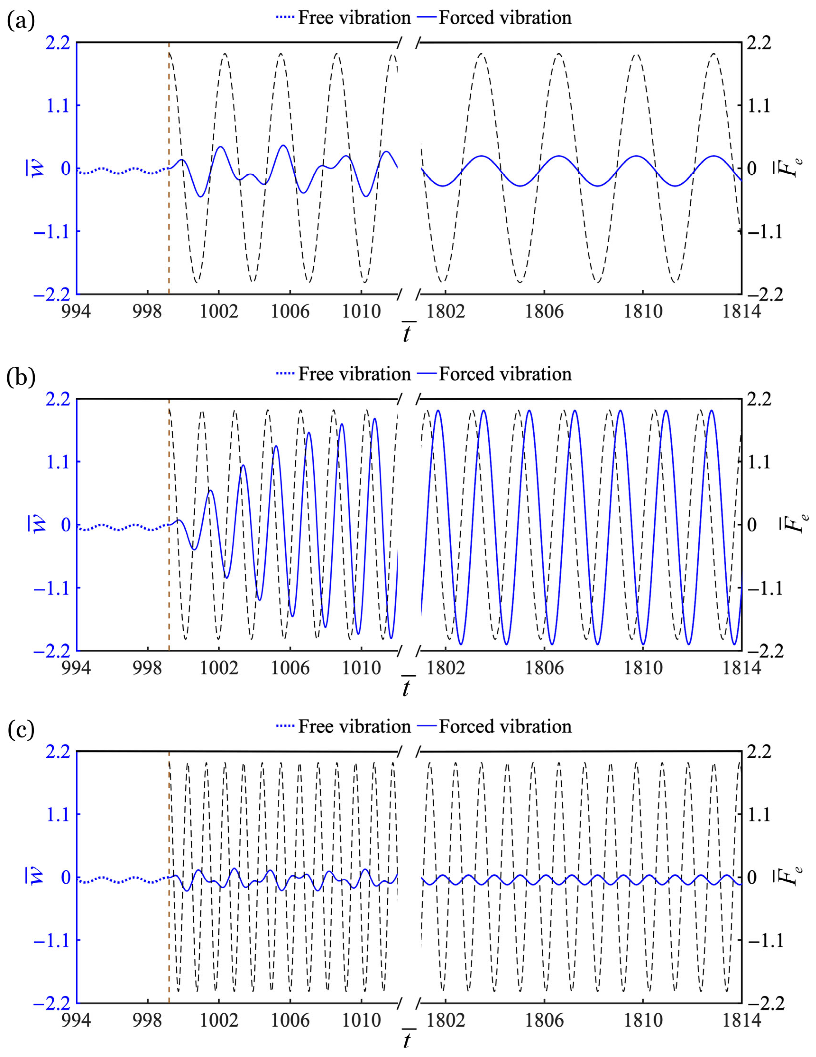
Figure 2 presents the time variation curves of the light-driven LCE self-oscillator under external periodic forcing, demonstrating three distinct phase-locking regimes governed by forcing frequency ω ¯ , namely in-phase, anti-phase, and quadrature synchronizations. The other system parameters are K ¯ f = 10 , α ¯ = 0.3 , b ¯ = 1 , β ¯ 1 = 0.01 , β ¯ 2 = 0.05 , and τ ¯ = 0.01 . Notably, the natural frequency of the LCE self-oscillator is ω ¯ 0 = 3.4 for this given parameter set. The initial conditions of w ¯ ( 0 ) = 0 and w ˙ ¯ ( 0 ) = 0 are set for the free vibration of the LCE self-oscillator. After entering its steady state, the external periodic forcing is applied with an initial phase difference of zero. For F ¯ e = 2 and ω ¯ = 2 , in-phase synchronization occurs, as evidenced in Figure 2a. The LCE self-oscillator and the external periodic forcing reach their peaks simultaneously, i.e., the phase difference is locked to Δ φ = 0 ° . Compared with the free vibration before the application of periodic forcing, the oscillatory amplitude of the forced vibration displays an increase. For F ¯ e = 2 and ω ¯ = 3.4 , the quadrature synchronization emerges in Figure 2b. The LCE self-oscillator locks to the external periodic forcing at a phase difference of Δ φ = 90 ° . The imposition of external forcing leads to a pronounced amplification in the oscillatory amplitude of the LCE self-oscillator. For F ¯ e = 2 and ω ¯ = 6 , Figure 2c describes the anti-phase synchronization. Obviously, the vibration peak of the LCE self-oscillator is opposite to the peak of the forcing, i.e., the phase difference is locked to Δ φ = 180 ° . The oscillatory amplitude after applying external forcing remains comparable to that observed prior to its application.
Moreover, the phase difference is explicitly visualized through the Lissajous figures in Figure 3, which correspond to the three cases in Figure 2. At phase difference of Δ φ = 0 ° , the trajectory degenerates into a diagonal line with positive slope, as depicted in Figure 3a. The circular orbit in Figure 3b suggests a phase difference of Δ φ = 90 ° . For the phase difference of Δ φ = 180 ° , the trajectory collapses into an anti-diagonal line with a negative slope in Figure 3c.

3.2. Mechanism Analysis

The previous subsection discussed the three phase-locking regimes in the time domain. Next, we will examine their dynamical signatures across the frequency domain and phase space.
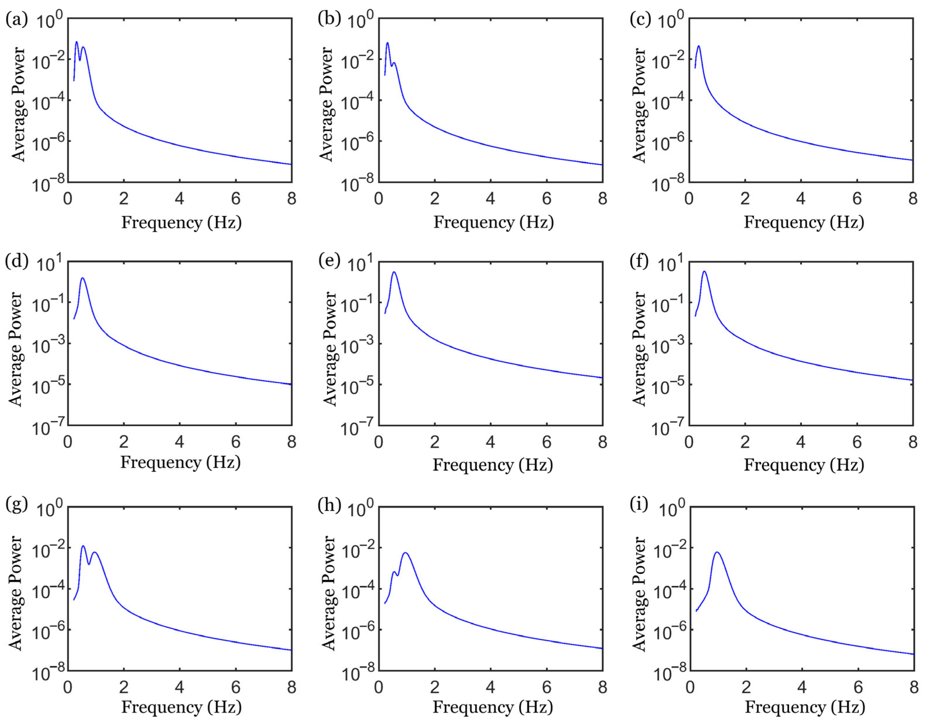
The time-frequency analyses based on the continuous wavelet transform corresponding to the three cases in Figure 2 are presented in Figure 4. For in-phase synchronization under F ¯ e = 2 and ω ¯ = 2 , as shown in Figure 4a,b, the averaged wavelet power spectra in the transient stage features dual peaks located at ω ¯ r e s p o n s e = 3.4 and ω ¯ r e s p o n s e = 2 . This bimodal distribution provides conclusive proof that the motion is initially driven by two incommensurate frequencies, with one being the natural frequency ω ¯ 0 = 3.4 of the LCE self-oscillator and the other being the forcing frequency ω ¯ = 2 . Whereas Figure 4c reveals a single spectral peak at ω ¯ r e s p o n s e = 2 in the steady state, confirming complete frequency locking of the LCE self-oscillator to the forcing frequency ω ¯ = 2 . For quadrature synchronization at F ¯ e = 2 and ω ¯ = 3.4 , only a single sharp peak is present at ω ¯ r e s p o n s e = 3.4 in both transient and steady-state spectra, as depicted in Figure 4d–f. This spectral signature confirms strict 1:1 frequency locking where the forcing frequency precisely matches the natural frequency of the LCE self-oscillator, i.e., ω ¯ = ω ¯ 0 = 3.4 . Notably, a minor harmonic peak accompanies the steady-state spectrum as well. Analogous to in-phase synchronization, anti-phase synchronization under F ¯ e = 2 and ω ¯ = 6 in Figure 4g–i exhibits dual spectral peaks at ω ¯ r e s p o n s e = 3.4 and ω ¯ r e s p o n s e = 6 during the transient stage, followed by a single peak at ω ¯ r e s p o n s e = 6 in the steady state. This spectral evolution demonstrates progressive frequency locking to the forcing frequency ω ¯ = 6 .
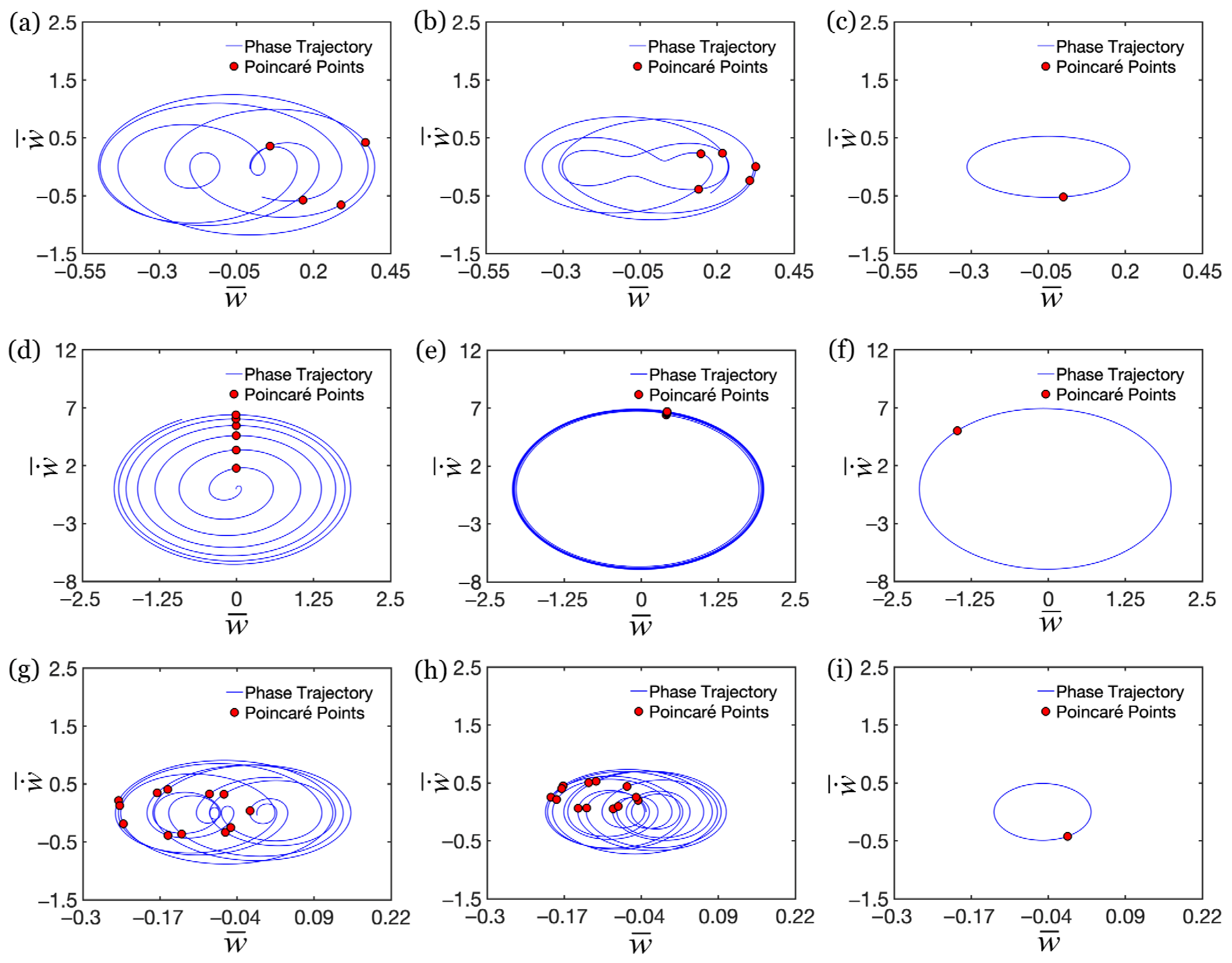
Following the analysis in the frequency domain, we now turn to the characterization in phase space. The phase trajectories and Poincaré points of the three cases in Figure 2 are plotted in Figure 5. For in-phase synchronization under F ¯ e = 2 and ω ¯ = 2 , as depicted in Figure 5a, the transient phase trajectories wind irregularly on the phase space, forming non-closed curve clusters, while the Poincaré points exhibit a dispersed distribution. Then the evolving tendency toward attractors is demonstrated in Figure 5b. Upon reaching steady state, the trajectories in Figure 5c evolve into a smooth closed limit cycle, and the Poincaré points collapse into a single fixed point. This signifies that the LCE self-oscillator undergoes periodic motion at a single frequency, perfectly synchronized with the forcing frequency. The phase space evolution for quadrature synchronization at F ¯ e = 2 and ω ¯ = 3.4 is displayed in Figure 5d–f. During the transient stage, phase trajectories form clusters of non-closed curves with dramatically varying curvature radii, while Poincaré points appear as discrete point chains exhibiting rapid spacing decay. Upon rapidly evolving into the steady state, phase trajectories converge to a closed elliptical limit cycle and Poincaré points collapse to a single fixed point, indicating periodicity restoration where the system identically revisits its state after each forcing cycle. This confirms strict 1:1 frequency locking, where the forcing frequency equals the natural frequency of the LCE self-oscillator, i.e., ω ¯ = ω ¯ 0 = 3.4 . Similar to in-phase synchronization, anti-phase synchronization at F ¯ e = 2 and ω ¯ = 6 in Figure 5g–i also manifests an evolution of the phase trajectory from non-closed curves to a closed limit cycle, and of the Poincaré points from dispersion to a single fixed point.
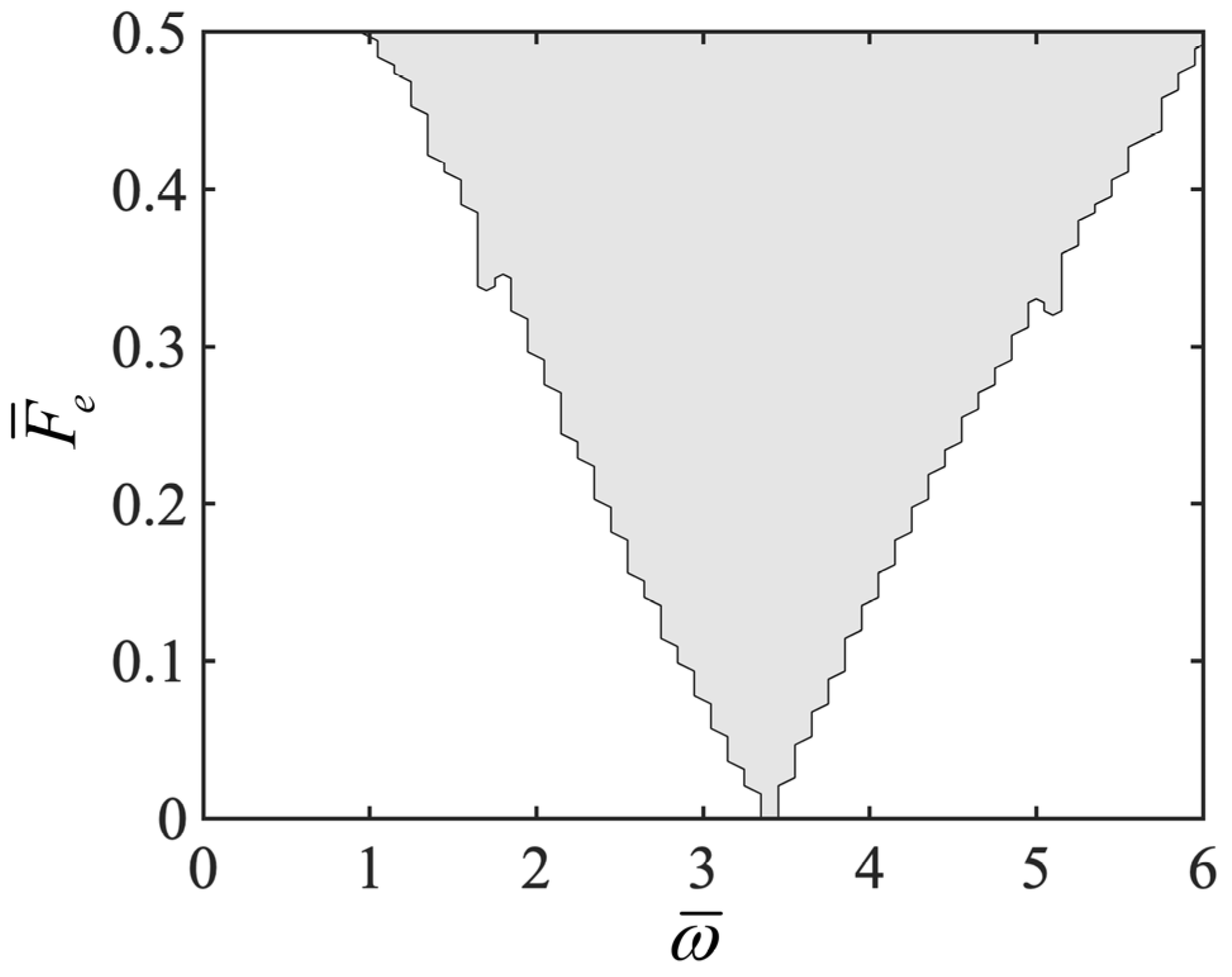
In addition, Arnold tongue is plotted in Figure 6, which is the characteristic tongue-shaped region in parameter space that represents frequency-locking phenomena in nonlinear oscillators subjected to periodic forcing. Clearly observed in Figure 6, the frequency ω ¯ r e s p o n s e of the LCE self-oscillator is locked to the forcing frequency ω ¯ within the gray V-shaped tongue. The tongue tip is located at the frequency ratio of ω ¯ / ω ¯ 0 = 1 : 1 . Moreover, stronger forcing widens the frequency-locking region. Specifically, as the forcing frequency approaches the natural frequency of the LCE self-oscillator, 1:1 frequency-locking occurs wherein the self-oscillator vibrates precisely at the forcing frequency. When the external forcing is sufficiently strong, it overcomes the intrinsic tendency of the self-oscillator to maintain its natural frequency, achieving full entrainment. The frequency-locking persists even for weak forcing amplitudes, provided the frequency detuning remains sufficiently small. Notably, different synchronization patterns emerge under varying parameters, which will be described in the subsequent parameter analysis.

4. Asymptotic Analysis Using Multi-Scale Method

This section will employ the multi-scale method [81,82] to derive the steady-state amplitude–frequency and phase–frequency responses of the LCE self-oscillator under external periodic forcing.
Through introducing ε = K ¯ f α ¯ b ¯ τ ¯ e α ¯ b ¯ 1 α ¯ b ¯ e α ¯ b ¯ ( e α ¯ b ¯ 1 ) 2 β ¯ 1 , c 1 = β ¯ 2 ( e α ¯ b ¯ 1 ) 2 K ¯ f α ¯ b ¯ τ ¯ ( e α ¯ b ¯ 1 α ¯ b ¯ e α ¯ b ¯ ) β ¯ 1 ( e α ¯ b ¯ 1 ) 2 , c 2 = K ¯ f α ¯ b ¯ e α ¯ b ¯ 1 , Equation (9) can be expressed as
w ¨ ^ ( t ¯ ) ε w ˙ ^ ( t ¯ ) c 1 w ˙ ^ ( t ¯ ) w ˙ ^ ( t ¯ ) + c 2 w ^ ( t ¯ ) = F ¯ e cos ω ¯ t ¯ .
Let x = w ^ , ω 0 = c 2 , F ¯ e = ε F 0 , and ω = ω 0 + ε σ with σ being the frequency detuning parameter, we have the following:
x ¨ ε ( x ˙ c 1 x ˙ x ˙ ) + ω 0 2 x = ε F 0 cos ( ω 0 + ε σ ) t .
We introduce time variables T n = ε n t ( n = 0 , 1 ) representing different scales to discuss the approximate solutions. The solutions for Equation (11) can be expressed as the following:
x = x 0 ( T 0 , T 1 ) + ε x 1 ( T 0 , T 1 ) ,
x ˙ = D 0 + ε D 1 ,
x ¨ = D 0 2 + 2 ε D 0 D 1 + O ( ε 2 ) .
where D n = T n ( n = 0 , 1 ) denotes the symbol of a partial differential operator.
Let f ( x , x ˙ ) = x ˙ c 1 | x ˙ | x ˙ . Substituting Equations (12)–(14) into Equation (11) and equating coefficients of like powers of ε gives the following system of linear partial differential equations:
D 0 2 x 0 + ω 0 2 x 0 = 0 ,
D 0 2 x 1 + ω 0 2 x 1 = 2 D 0 D 1 x 0 + f D 0 x 0 + F 0 cos ω 0 T 0 + σ T 1 .
The solution to the zeroth-order approximation Equation (15) is expressed in complex-valued form as the following:
x 0 = A ( T 1 ) e i ω 0 T 0 + A ¯ ( T 1 ) e i ω 0 T 0 ,
where A is a complex-valued function to be determined, and A ¯ denotes its complex conjugate. A is expressed in exponential form as
A ( T 1 ) = 1 2 a ( T 1 ) e i η ( T 1 ) ,
where both a ( T 1 ) and η ( T 1 ) are real-valued functions of time.
Substituting Equation (17) into the right-hand side of the first-order approximation Equation (16) yields the following:
D 0 2 x 1 + ω 0 2 x 1 = 2 i ω 0 D 1 A e i ω 0 T 0 + 2 i ω 0 D 1 A ¯ e i ω 0 T 0 + f D 0 x 0 + F 0 cos ω 0 T 0 + σ T 1 ,
where f ( D 0 x 0 ) is a periodic function of T 0 , and it can be expanded as a Fourier series like f ( D 0 x 0 ) = n f n ( A , A ¯ ) e i n ω 0 T 0 with f n ( A , A ¯ ) = ω 0 2 π 0 2 π / ω 0 f e i n ω 0 T 0 d T 0 .
Equation (19) can be rewritten as follows:
D 0 2 x 1 + ω 0 2 x 1 = 2 i ω 0 D 1 A e i ω 0 T 0 + 2 i ω 0 D 1 A ¯ e i ω 0 T 0 + i ω 0 A e i ω 0 T 0 i ω 0 A ¯ e i ω 0 T 0 c 1 i 4 a 2 ω 0 2 3 π e i ( ω 0 T 0 + η ) + c 1 i 4 a 2 ω 0 2 3 π e i ( ω 0 T 0 + η ) + + F 0 2 e i ( ω 0 T 0 + σ T 1 ) + F 0 2 e i ( ω 0 T 0 + σ T 1 ) .
To prevent the emergence of secular terms, the sum of the coefficients of e i ω 0 T 0 should vanish. This requires that the function A satisfies the following condition:
2 i ω 0 D 1 A + i ω 0 A i 8 a ω 0 2 c 1 3 π A + F 0 2 e i σ T 1 = 0 .
Through substituting Equation (18) into Equation (21), we obtain the following:
a + i a η = a 2 4 a 2 ω 0 c 1 3 π i F 0 2 ω 0 e i ψ ,
where ψ ( T 1 ) = σ T 1 η ( T 1 ) is the phase difference between the forcing and response.
Given e i ψ = cos ψ + i sin ψ and η = σ ψ , separating the real and imaginary components of Equation (22) yields amplitude and phase equations:
a = a 2 4 a 2 ω 0 c 1 3 π + F 0 2 ω 0 sin ψ ,
a ( σ ψ ) = F 0 2 ω 0 cos ψ .
a = 0 and ψ = 0 correspond to the steady-state amplitude a and phase difference ψ , respectively:
4 a 2 ω 0 c 1 3 π a 2 = F 0 2 ω 0 sin ψ ,
a σ = F 0 2 ω 0 cos ψ .
Proceeding algebraically, we eliminate ψ by squaring both sides of Equations (25) and (26) and adding the resulting expressions. Alternatively, dividing one equation by the other cancels a . Then, we have the following:
4 a 2 ω 0 c 1 3 π a 2 2 + a σ 2 = F 0 2 ω 0 2 ,
tan ψ = 3 π 8 a ω 0 c 1 6 π σ .
To sum up, the steady-state amplitude–frequency and phase–frequency responses for x are derivable from Equations (27) and (28).
Given x = w ^ , the amplitude and phase difference for w ^ are A ¯ r e s p o n s e = a and Δ φ = ψ , respectively. Thus, by substituting c 1 = β ¯ 2 ( e α ¯ b ¯ 1 ) 2 K ¯ f α ¯ b ¯ τ ¯ ( e α ¯ b ¯ 1 α ¯ b ¯ e α ¯ b ¯ ) β ¯ 1 ( e α ¯ b ¯ 1 ) 2 , ω 0 = c 2 = K ¯ f α ¯ b ¯ e α ¯ b ¯ 1 and ε = K ¯ f α ¯ b ¯ τ ¯ e α ¯ b ¯ 1 α ¯ b ¯ e α ¯ b ¯ ( e α ¯ b ¯ 1 ) 2 β ¯ 1 , the steady-state amplitude–frequency and phase–frequency responses for the LCE self-oscillator are derivable from Equations (29) and (30):
4 A ¯ r e s p o n s e 2 c 2 c 1 3 π A ¯ r e s p o n s e 2 2 + A ¯ r e s p o n s e σ 2 = F ¯ e 2 4 ε 2 c 2 ,
tan Δ φ = 3 π 8 A ¯ r e s p o n s e c 2 c 1 6 π σ ,
where σ = ω ¯ ω ¯ 0 ε refers to the frequency detuning parameter. Significantly, the case σ = 0 corresponds to 1:1 frequency-locking, i.e., ω ¯ = ω ¯ 0 .

5. Response Characteristics of LCE Self-Oscillator Under Periodic Forcing

As mentioned above, variations in the amplitude and frequency of the external periodic forcing could alter the self-oscillatory response of the LCE self-oscillator. This section will employ numerical and analytical approaches to comparatively examine the response characteristics of the LCE self-oscillator under external periodic forcing.

5.1. Effect of Forcing Frequency

Figure 7 describes how the forcing frequency ω ¯ affects the self-oscillatory response of the LCE self-oscillator, with the other parameters being K ¯ f = 10 , α ¯ = 0.3 , b ¯ = 1 , β ¯ 1 = 0.01 , β ¯ 2 = 0.05 , τ ¯ = 0.01 and F ¯ e = 2 . Figure 7a depicts the initial growth followed by decay in response amplitude with the increasing forcing frequency ω ¯ . Specifically, the response amplitude peaks when the forcing frequency equals the natural frequency, i.e., ω ¯ = ω ¯ 0 = 3.4 . As the forcing frequency ω ¯ deviates from the natural frequency ω ¯ 0 , whether higher or lower, the amplitude diminishes. If the forcing varies too rapidly, the system struggles to follow, requiring stronger forcing to maintain synchronization, which reduces the amplitude. Conversely, if the forcing varies too slowly, it cannot replenish the energy efficiently, also resulting in a decline of amplitude. Clearly observed in Figure 7b, the external forcing and self-oscillatory response maintain a consistent phase offset of Δ φ = 90 ° at ω ¯ = ω ¯ 0 . ω ¯ < ω ¯ 0 yields in-phase synchronization with Δ φ = 0 ° , whereas ω ¯ > ω ¯ 0 exhibits anti-phase synchronization with Δ φ = 180 ° . It is apparent that a close correspondence exists between numerical and analytical results. Furthermore, in future experimental validation, different types of synchronization phenomena can be accessed in an LCE self-oscillator with fixed parameters by adjusting the frequency of the external periodic forcing.

5.2. Effect of Forcing Amplitude

Figure 8 displays how the forcing amplitude F ¯ e influences the self-oscillatory response of the LCE self-oscillator, where the other parameters are K ¯ f = 10 , α ¯ = 0.3 , b ¯ = 1 , β ¯ 1 = 0.01 , β ¯ 2 = 0.05 , τ ¯ = 0.01 and ω ¯ = 3.4 . Figure 8a demonstrates a monotonic increase in the response amplitude with growing forcing amplitude F ¯ e . Given the specified parameters, the forcing frequency equals the natural frequency, i.e., ω ¯ = ω ¯ 0 = 3.4 , thus enabling 1:1 frequency-locking. A stronger external forcing propels the LCE self-oscillator more effectively, producing oscillations with greater amplitude. Correspondingly, quadrature synchronization is achieved for ω ¯ = ω ¯ 0 , and the phase difference remains invariant at Δ φ = 90 ° under changes in forcing amplitude, as plotted in Figure 8b. Likewise, excellent agreement is observed between numerical and analytical results. In future experimental demonstrations, for an LCE self-oscillator that has been phase-locked and synchronized with the external periodic forcing, its amplitude can be regulated by increasing the forcing amplitude.
In summary, the response characteristics described above can be effectively exploited to achieve active manipulation and optimized design of the LCE self-oscillators. External periodic forcing offers a non-contact means of control, enabling tailored manipulation of self-oscillatory behavior in terms of frequency, amplitude, and phase. Such deterministic responses facilitate programmable motion regimes. Furthermore, for practical applications in noisy and unpredictable environments, LCE self-oscillators can be engineered to exhibit enhanced robustness against perturbations—or even constructively harness stochastic disturbances to realize specific functional capabilities.

6. Response Regulation of LCE Self-Oscillator via System Parameters

Since variations in system parameters could influence the natural frequency of the LCE self-oscillator, a constant external periodic forcing combined with a shifted natural frequency may alter the self-oscillatory response. This section will employ numerical and analytical methods to comparatively examine how system parameters regulate the LCE self-oscillator under external periodic forcing. Notably, all parameter values used in the following parametric analysis fall within the self-oscillation regime.

6.1. Regulation by Elastic Coefficient

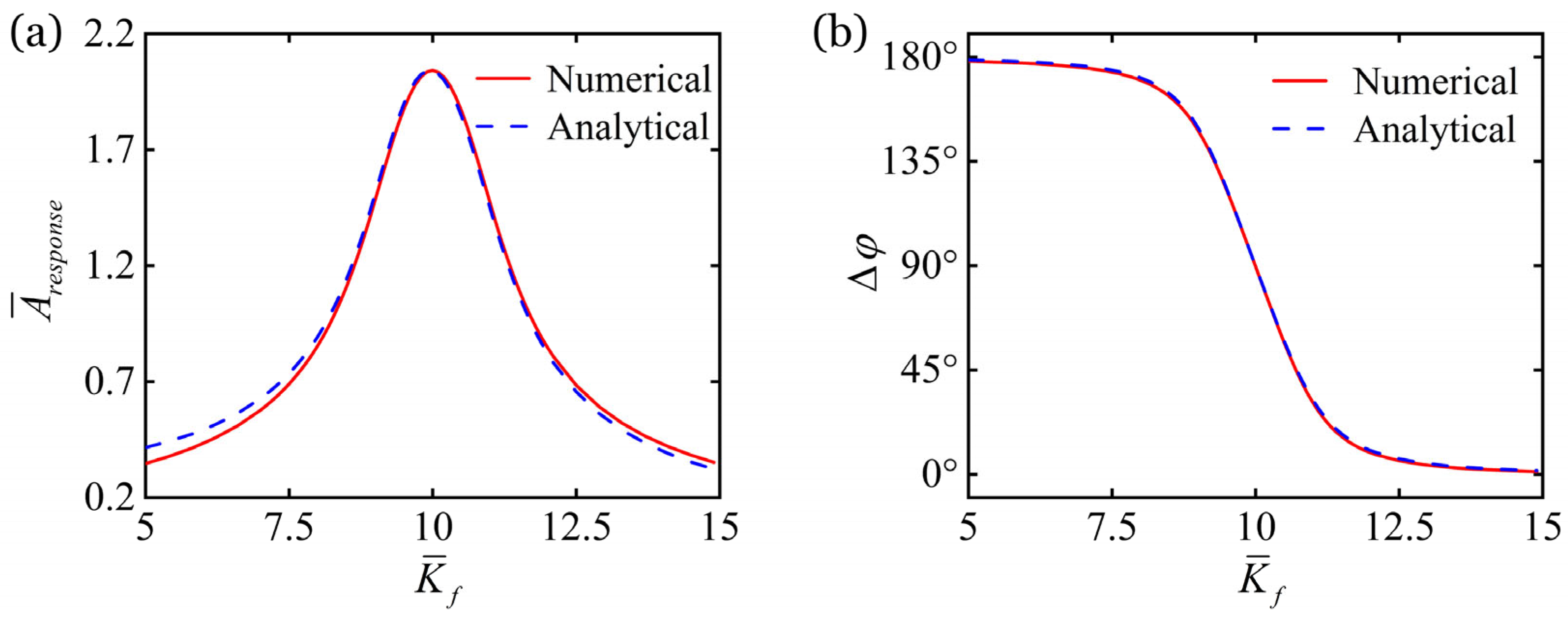
As illustrated in Figure 9, the response regulation of the LCE self-oscillator under external periodic forcing by elastic coefficient K ¯ f of LCE fiber is presented, where the other parameters are α ¯ = 0.3 , b ¯ = 1 , β ¯ 1 = 0.01 , β ¯ 2 = 0.05 , τ ¯ = 0.01 , F ¯ e = 2 , and ω ¯ = 3.4 . In self-oscillations, a rise in the elastic coefficient K ¯ f generates a greater driving force from the LCE fiber, thereby enhancing the natural frequency ω ¯ 0 . Consequently, Figure 9a depicts how the response amplitude initially grows and subsequently diminishes as the elastic coefficient K ¯ f increases. The peak amplitude occurs at K ¯ f = 10 , where the natural frequency equals the forcing frequency, i.e., ω ¯ 0 = ω ¯ = 3.4 . In addition, the variation of phase difference with the rising elastic coefficient K ¯ f is clearly witnessed in Figure 9b. K ¯ f < 10 corresponds to ω ¯ 0 < ω ¯ = 3.4 , anti-phase synchronization with Δ φ = 180 ° occurs. K ¯ f > 10 signifies ω ¯ 0 > ω ¯ = 3.4 , in-phase synchronization with Δ φ = 0 ° emerges. Furthermore, close agreement between numerical and analytical results persists, exhibiting minor deviations exclusively at small values of K ¯ f . Notably, this finding provides a method to experimentally observe pronounced synchronization by tuning the elastic coefficient of the LCE fiber to shift its frequency.

6.2. Regulation by Thermal Expansion Coefficient

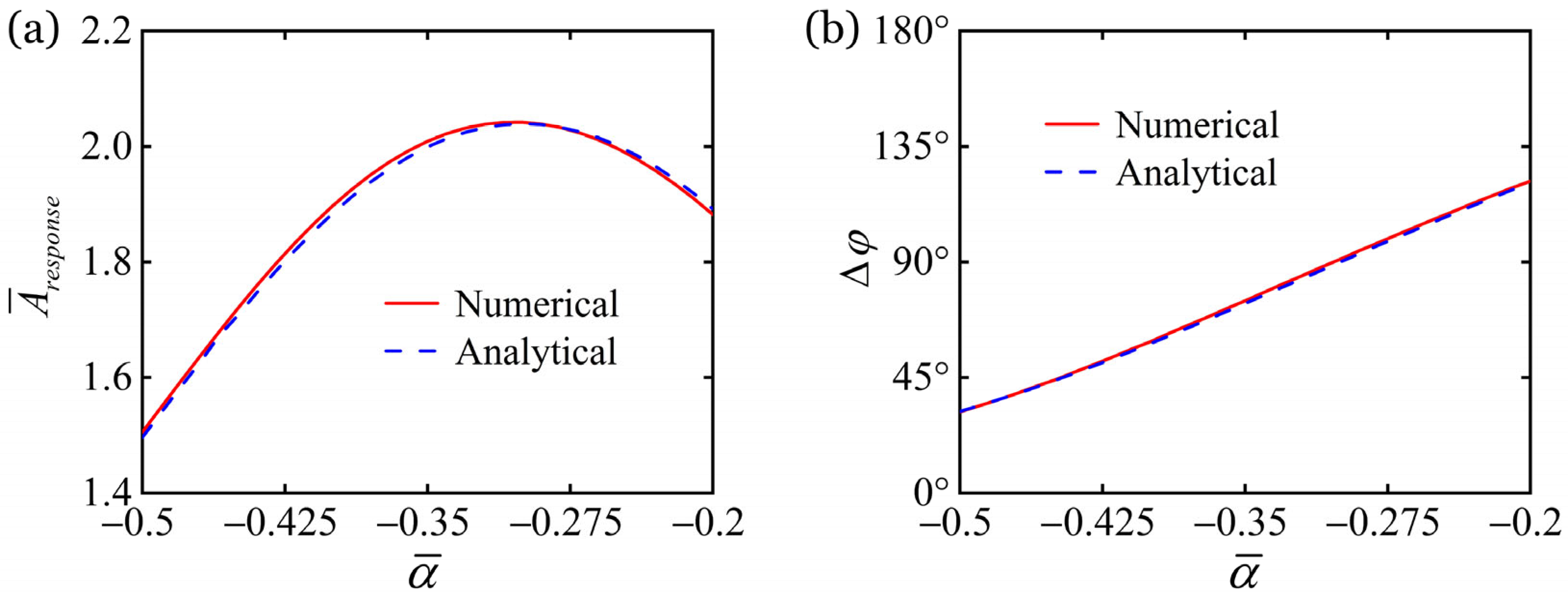
The response regulation of the LCE self-oscillator under external periodic forcing by the thermal expansion coefficient α ¯ is illustrated in Figure 10, with the other parameters being K ¯ f = 10 , b ¯ = 1 , β ¯ 1 = 0.01 , β ¯ 2 = 0.05 , τ ¯ = 0.01 , F ¯ e = 2 and ω ¯ = 3.4 . In self-oscillations, an elevation in the absolute value of the thermal expansion coefficient α ¯ will raise the natural frequency ω ¯ 0 . Thus, amplitude enhancement prior to progressive attenuation under increasing thermal expansion coefficient α ¯ is captured in Figure 10a. The maximum amplitude is achieved at α ¯ = 0.3 , where the natural frequency coincides with the forcing frequency, i.e., ω ¯ 0 = ω ¯ = 3.4 . Moreover, the change in phase difference as the thermal expansion coefficient α ¯ grows is distinctly shown in Figure 10b. 0.5 < α ¯ < 0.2 corresponds to a slight variation in the natural frequency near ω ¯ 0 = 3.4 , suggesting a close proximity to the quadrature synchronization with Δ φ = 90 ° at 1:1 frequency locking. Similarly, a strong consistency between numerical and analytical results persists.

6.3. Regulation by Gradient of Heat Flux

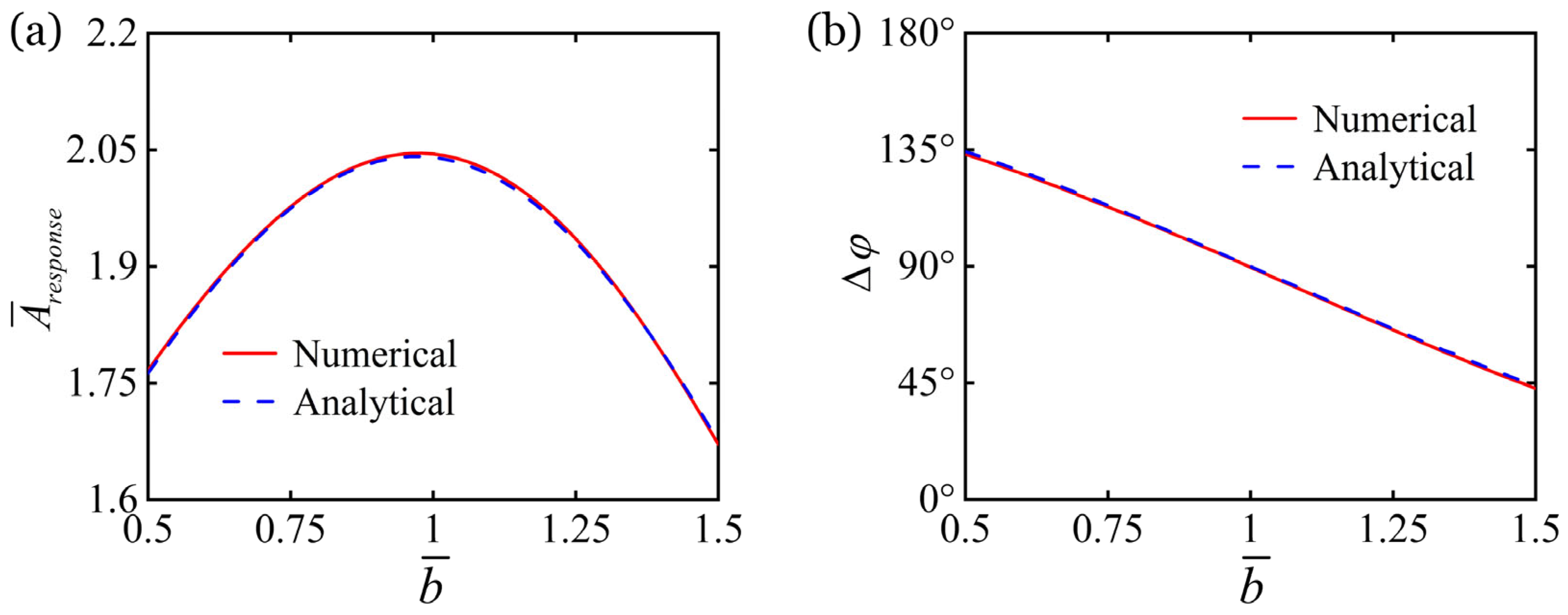
Figure 11 describes how gradient of heat flux b ¯ regulates the self-oscillatory response of the LCE self-oscillator under external periodic forcing, among which the other parameters are K ¯ f = 10 , α ¯ = 0.3 , β ¯ 1 = 0.01 , β ¯ 2 = 0.05 , τ ¯ = 0.01 , F ¯ e = 2 and ω ¯ = 3.4 . Since increasing the gradient of heat flux b ¯ leads to a gradual enhancement in the natural frequency ω ¯ 0 of the LCE self-oscillator, Figure 11a reveals that a larger gradient first amplifies and then suppresses the response amplitude. When b ¯ = 1 , the natural frequency exactly matches the forcing frequency, namely ω ¯ 0 = ω ¯ = 3.4 , thus resulting in maximum response amplitude. Furthermore, the progression of the phase difference with increasing gradient b ¯ is demonstrated in Figure 11b. For 0.5 < b ¯ < 1.5 , the natural frequency exhibits minimal deviation around ω ¯ 0 = 3.4 , placing the system near the quadrature synchronization with Δ φ = 90 ° of 1:1 frequency locking. Yet again, remarkable consistency is evident in numerical–analytical comparisons.

6.4. Regulation by First Damping Coefficient

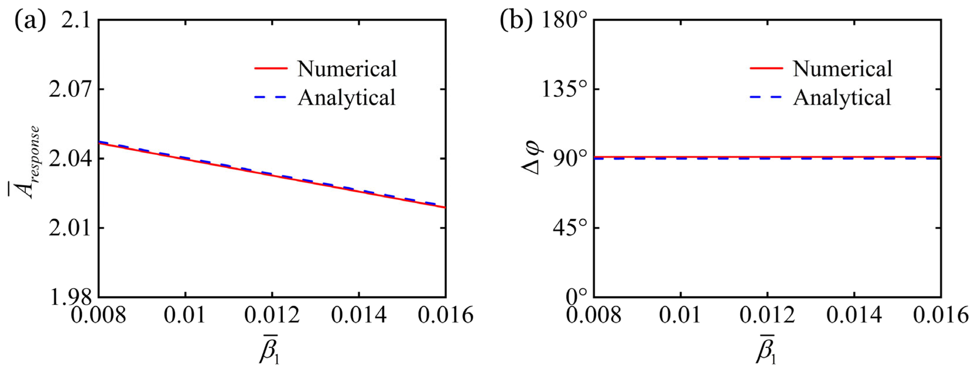
As illustrated in Figure 12, the response regulation of the first damping coefficient β ¯ 1 on the LCE self-oscillator under external periodic forcing is provided, with the other parameters being K ¯ f = 10 , α ¯ = 0.3 , b ¯ = 1 , β ¯ 2 = 0.05 , τ ¯ = 0.01 , F ¯ e = 2 and ω ¯ = 3.4 . It is evident in Figure 12a that as damping rises, the consequent intensification of energy dissipation results in diminished response amplitude. However, changes in the first damping coefficient β ¯ 1 exhibit no impact on the natural frequency, which remains constant at ω ¯ 0 = 3.4 . Consequently, for ω ¯ 0 = ω ¯ = 3.4 , the phase difference consistently maintains Δ φ = 90 ° regardless of changes in the first damping coefficient β ¯ 1 , as demonstrated in Figure 12b. Once again, close correspondence emerges between numerical and analytical results.

6.5. Regulation by Second Damping Coefficient

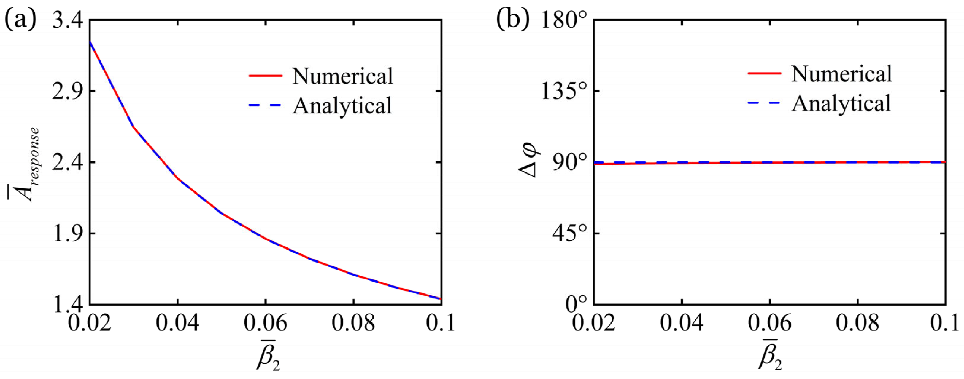
Figure 13 describes how the second damping coefficient β ¯ 2 regulates the self-oscillatory response of the LCE self-oscillator under external periodic forcing, with the other parameters being K ¯ f = 10 , α ¯ = 0.3 , b ¯ = 1 , β ¯ 1 = 0.01 , τ ¯ = 0.01 , F ¯ e = 2 and ω ¯ = 3.4 . In the LCE self-oscillator, elevated damping promotes greater energy dissipation, thereby decreasing the amplitude. Thus, Figure 13a visualizes the descending trend of response amplitude versus a higher damping coefficient β ¯ 2 . Similarly, the natural frequency is maintained at ω ¯ 0 = 3.4 , independently of the second damping coefficient β ¯ 2 . Thus, for ω ¯ 0 = ω ¯ = 3.4 , the phase difference remains unchanged at Δ φ = 90 ° despite variations in the second damping coefficient β ¯ 2 , as evidenced by Figure 13b. Likewise, strong alignment persists across numerical and analytical results.

6.6. Regulation by Thermal Characteristic Time

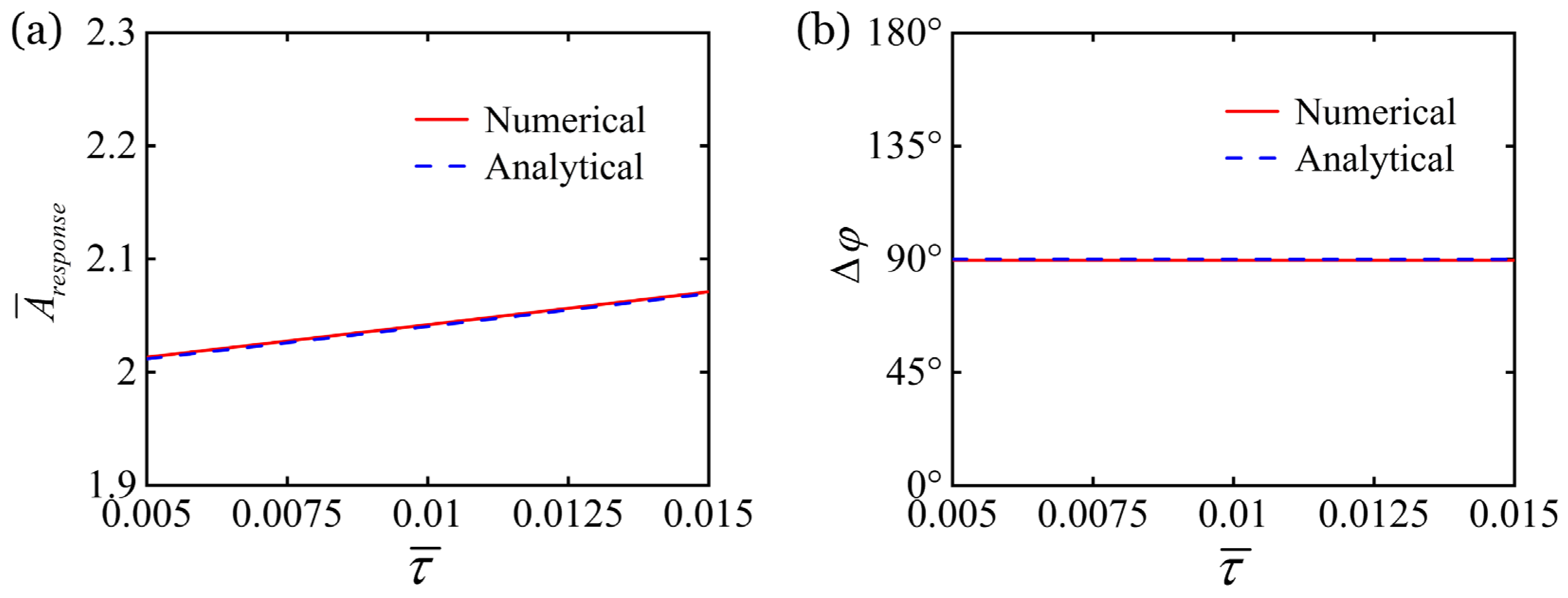
The response regulation of the LCE self-oscillator under external periodic forcing by thermal characteristic time τ ¯ is illustrated in Figure 14, where the other parameters are K ¯ f = 10 , α ¯ = 0.3 , b ¯ = 1 , β ¯ 1 = 0.01 , β ¯ 2 = 0.05 , F ¯ e = 2 and ω ¯ = 3.4 . The growth in thermal characteristic time τ ¯ augments photothermal conversion in the LCE fiber, directly amplifying the response amplitude of the LCE self-oscillator. Accordingly, the growth in response amplitude with increasing thermal characteristic time τ ¯ is shown in Figure 14a. Since the natural frequency is unaffected by alterations to the thermal characteristic time τ ¯ , it remains fixed at ω ¯ 0 = 3.4 . This invariance leads to a stable phase difference of Δ φ = 90 ° for ω ¯ 0 = ω ¯ = 3.4 under any modification of the thermal characteristic time τ ¯ , as displayed in Figure 14b. Yet again, numerical and analytical solutions exhibit exceptional concordance.
To sum up, the system parameters of LCE self-oscillators can be inversely designed according to the target operational environment to either efficiently harness ambient energy or robustly reject environmental disturbances. For LCE-based energy harvesters, the goal is to maximize the conversion of ambient mechanical vibrations into usable energy. This can be achieved by optimizing the oscillator parameters to promote synchronization with predominant environmental frequencies, thereby improving the energy capture efficiency. Conversely, for high-precision sensors utilizing LCE self-oscillators, it is essential to prevent the self-oscillatory frequency from being entrained or shifted by stray periodic signals. Targeted parameter design can avoid resonant interference bands, thus improving interference immunity.

7. Conclusions

Unlike previous studies on isolated LCE self-oscillators, we introduce external environmental disturbances into the system to investigate the synchronization behavior arising from the interplay between self-oscillation and external periodic forcing. To characterize the response of self-oscillation under external periodic forcing, an LCE self-oscillator is considered using a photothermally-responsive LCE fiber and a mass block within a linear light field. Building upon the photothermally-responsive LCE model, we develop a theoretical model for the light-driven LCE self-oscillator under external periodic forcing. Three distinct phase-locking regimes are identified: in-phase, anti-phase, and quadrature synchronizations. The underlying mechanisms are explored through time-domain, frequency-domain, and phase-space analyses. In addition, Arnold tongue is plotted to describe the frequency-locking region. The frequency of the LCE self-oscillator locks to the forcing frequency within the tongue, with the tongue tip located at the frequency ratio of ω ¯ / ω ¯ 0 = 1 : 1 . And stronger forcing widens the frequency-locking region.
Utilizing the multi-scale method, we obtain the steady-state amplitude–frequency and phase–frequency responses of the LCE self-oscillator under external periodic forcing. The response amplitude displays an initial growth followed by decay with increasing forcing frequency ω ¯ , but a monotonic increase with growing forcing amplitude F ¯ e . For ω ¯ = ω ¯ 0 , 1:1 frequency-locking emerges, where the response amplitude peaks and a consistent phase offset of Δ φ = 90 ° is maintained. In-phase synchronization with Δ φ = 0 ° yields for ω ¯ < ω ¯ 0 , whereas anti-phase synchronization with Δ φ = 180 ° occurs for ω ¯ > ω ¯ 0 . Moreover, variations in the elastic coefficient K ¯ f of LCE fiber, thermal expansion coefficient α ¯ , and gradient of heat flux b ¯ alter the natural frequency ω ¯ 0 of the LCE self-oscillator, thereby modifying its self-oscillatory response under periodic forcing. In contrast, the first and second damping coefficients β ¯ 1 , β ¯ 2 and thermal characteristic time τ ¯ exhibit no effect on the natural frequency ω ¯ 0 , and therefore the phase difference consistently maintains at Δ φ = 90 ° for ω ¯ = ω ¯ 0 . Notably, a close correspondence exists between numerical and analytical results.
Nevertheless, this study still has several limitations. First, the theoretical framework incorporates certain simplifying assumptions, such as neglecting nonlinear constitutive behavior of the LCE material, which may affect the accuracy of model predictions under real-world conditions. Moving forward, we will explore adopting more generalized modeling approaches that account for nonlinear constitutive behavior. A second limitation lies in the representation of external disturbances as a purely periodic forcing, which offers only an approximate depiction of actual vibrational environments. In future work, we will employ more complex excitation patterns, such as random or multi-frequency excitation, to more accurately replicate real-world environments. Additionally, experimental validation will be conducted in the next research phase to further verify the numerical and analytical results. The self-oscillation frequency inherent to the LCE fiber system was found to be minimal, limiting clear observability. The current work provides theoretical support for improving experimental observability of synchronization. For instance, modifying system parameters, such as the elastic coefficient of the LCE fiber, can significantly alter the frequency.
This study establishes the feasibility of actively controlling and optimizing LCE self-oscillators through external periodic forcing. It provides a non-contact control strategy for precise manipulation of the self-oscillatory motion. Insights into phase-locking synchronization contribute to the design of LCE self-oscillators with enhanced robustness against environmental noise and unpredictable disturbances—even turning such interference into functional advantages. Moreover, this work lays a theoretical foundation for further explorations on collective phase-locking dynamics and group synchronization behaviors in coupled LCE self-oscillator networks.

Author Contributions

Conceptualization, Y.D., and P.X.; methodology, Y.D.; software, Y.D., and K.W.; validation, K.W., and X.J.; data curation, K.W., and X.J.; writing—original draft, Y.D., and K.W.; writing—review and editing, Y.D., and P.X. All authors have read and agreed to the published version of the manuscript.

Funding

This study is supported by the National Natural Science Foundation of China (Grant No. 12172001), University Natural Science Research Project of Anhui Province (Grant No. 2022AH020029), Anhui Provincial Natural Science Foundation (Grant Nos. 2208085Y01 and 2008085QA23), and Housing and Urban-Rural Development Science and Technology Project of Anhui Province (Grant No. 2023-YF129).

Data Availability Statement

The original contributions presented in the study are included in the article. Further inquiries can be directed to the corresponding author.

Conflicts of Interest

The authors declare no conflicts of interest.

References

  1. Liu, J.; Xu, L.; Ji, Q.; Chang, L.; Hu, Y.; Peng, Q.; He, X. A MXene-based light-driven actuator and motor with self-sustained oscillation for versatile applications. Adv. Funct. Mater. 2024, 34, 2310955. [Google Scholar] [CrossRef]
  2. Zheng, E.; Brandenbourger, M.; Robinet, L.; Schall, P.; Lerner, E.; Coulais, C. Self-oscillation and synchronization transitions in elastoactive structures. Phys. Rev. Lett. 2023, 130, 178202. [Google Scholar] [CrossRef]
  3. Chakrabarti, A.; Choi, G.P.T.; Mahadevan, L. Self-excited motions of volatile drops on swellable sheets. Phys. Rev. Lett. 2020, 124, 258002. [Google Scholar] [CrossRef]
  4. Niehues, J.; Jensen, G.G.; Haerter, J.O. Self-organized quantization and oscillations on continuous fixed-energy sandpiles. Phys. Rev. E 2022, 105, 034314. [Google Scholar] [CrossRef] [PubMed]
  5. Charroyer, L.; Chiello, O.; Sinou, J.J. Self-excited vibrations of a non-smooth contact dynamical system with planar friction based on the shooting method. Int. J. Mech. Sci. 2018, 144, 90–101. [Google Scholar] [CrossRef]
  6. Sangwan, V.; Taneja, A.; Mukherjee, S. Design of a robust self-excited biped walking mechanism. Mech. Mach. Theory 2004, 39, 1385–1397. [Google Scholar] [CrossRef]
  7. Zhang, B.; Yan, Y.; Dong, X.; Dykman, M.I.; Chan, H.B. Frequency stabilization of self-sustained oscillations in a sideband-driven electromechanical resonator. Phys. Rev. Appl. 2024, 22, 034072. [Google Scholar] [CrossRef]
  8. Yang, H.; Yin, X.; Zhang, C.; Chen, B.; Sun, P.; Xu, Y. Weaving liquid crystal elastomer fiber actuators for multifunctional soft robotics. Sci. Adv. 2025, 11, eads3058. [Google Scholar] [CrossRef]
  9. He, Q.; Yin, R.; Hua, Y.; Jiao, W.; Mo, C.; Shu, H.; Raney, J.R. A modular strategy for distributed, embodied control of electronics-free soft robots. Sci. Adv. 2023, 9, eade9247. [Google Scholar] [CrossRef]
  10. Nie, Z.Z.; Wang, M.; Yang, H. Self-sustainable autonomous soft actuators. Commun. Chem. 2024, 7, 58. [Google Scholar] [CrossRef]
  11. Zhao, D.; Liu, Y. A prototype for light-electric harvester based on light sensitive liquid crystal elastomer cantilever. Energy 2020, 198, 117351. [Google Scholar] [CrossRef]
  12. He, X.; Aizenberg, M.; Kuksenok, O.; Zarzar, L.D.; Shastri, A.; Balazs, A.C.; Aizenberg, J. Synthetic homeostatic materials with chemo-mechano-chemical self-regulation. Nature 2012, 487, 214–218. [Google Scholar] [CrossRef]
  13. Tang, Y.; Li, M.; Wang, T.; Dong, X.; Hu, W.; Sitti, M. Wireless miniature magnetic phase-change soft actuators. Adv. Mater. 2022, 34, 2204185. [Google Scholar] [CrossRef]
  14. Yang, L.; Miao, J.; Li, G.; Ren, R.; Zhang, T.; Guo, D.; Tang, Y.; Shang, W.; Shen, Y. Soft tunable gelatin robot with insect-like claw for grasping, transportation, and delivery. ACS Appl. Polym. Mater. 2022, 4, 5431–5440. [Google Scholar] [CrossRef]
  15. Zhu, Q.; Liu, W.; Khoruzhenko, O.; Breu, J.; Bai, H.; Hong, W.; Zheng, Q.; Wu, Z. Closed twisted hydrogel ribbons with self-sustained motions under static light irradiation. Adv. Mater. 2024, 36, 2314152. [Google Scholar] [CrossRef]
  16. Dai, L.; Xu, J.; Xiao, R. Modeling the stimulus-responsive behaviors of fiber-reinforced soft materials. Int. J. Appl. Mech. 2024, 16, 2450041. [Google Scholar] [CrossRef]
  17. Xiao, R.; Mai, T.T.; Urayama, K.; Gong, J.P.; Qu, S. Micromechanical modeling of the multi-axial deformation behavior in double network hydrogels. Int. J. Plast. 2021, 137, 102901. [Google Scholar] [CrossRef]
  18. Lin, J.; Zheng, S.Y.; Xiao, R.; Yin, J.; Wu, Z.L.; Zheng, Q.; Qian, J. Constitutive behaviors of tough physical hydrogels with dynamic metal-coordinated bonds. J. Mech. Phys. Solids 2020, 139, 103935. [Google Scholar] [CrossRef]
  19. Boissonade, J.; Kepper, P.D. Multiple types of spatio-temporal oscillations induced by differential diffusion in the Landolt reaction. Phys. Chem. Chem. Phys. 2011, 13, 4132–4137. [Google Scholar] [CrossRef]
  20. Li, K.; Wu, P.; Cai, S. Chemomechanical oscillations in a responsive gel induced by an autocatalytic reaction. J. Appl. Phys. 2014, 116, 043523. [Google Scholar] [CrossRef]
  21. Zou, J.; Ma, Y.; Liu, C.; Xie, Y.; Dai, X.; Li, X.; Li, S.; Peng, S.; Yue, Y.; Wang, S.; et al. Self-powered sensor based on compressible ionic gel electrolyte for simultaneous determination of temperature and pressure. InfoMat 2024, 6, e12545. [Google Scholar] [CrossRef]
  22. Tang, C.; Du, B.; Jiang, S.; Wang, Z.; Liu, X.J.; Zhao, H. A review on high-frequency dielectric elastomer actuators: Materials, dynamics, and applications. Adv. Intell. Syst. 2024, 6, 2300047. [Google Scholar] [CrossRef]
  23. Yang, H.; Zhang, C.; Chen, B.; Wang, Z.; Xu, Y.; Xiao, R. Bioinspired design of stimuli-responsive artificial muscles with multiple actuation modes. Smart Mater. Struct. 2023, 32, 085023. [Google Scholar] [CrossRef]
  24. Wang, Y.; Dang, A.; Zhang, Z.; Yin, R.; Gao, Y.; Feng, L.; Yang, S. Repeatable and reprogrammable shape morphing from photoresponsive gold nanorod/liquid crystal elastomers. Adv. Mater. 2020, 32, 2004270. [Google Scholar] [CrossRef]
  25. Wang, Y.; Liu, J.; Yang, S. Multi-functional liquid crystal elastomer composites. Appl. Phys. Rev. 2022, 9, 011301. [Google Scholar] [CrossRef]
  26. Wang, Y.; Yin, R.; Jin, L.; Liu, M.; Gao, Y.; Raney, J.; Yang, S. 3D-printed photoresponsive liquid crystal elastomer composites for free-form actuation. Adv. Funct. Mater. 2023, 33, 2210614. [Google Scholar] [CrossRef]
  27. Kang, W.; Cheng, Q.; Liu, C.; Wang, Z.; Li, D.; Liang, X. A constitutive model of monodomain liquid crystal elastomers with the thermal-mechanical-nematic order coupling. J. Mech. Phys. Solids 2025, 196, 105995. [Google Scholar] [CrossRef]
  28. Xu, Z.; Chen, Y.; Zhu, L.; Ge, Q.; Wu, Z.L.; Qu, S.; Xiao, R. Tailored helix morphing of 3D-printed liquid crystal elastomer bilayers. Cell Rep. Phys. Sci. 2025, 6, 102835. [Google Scholar] [CrossRef]
  29. Zhu, L.; He, M.; Chen, B.; Qian, J.; Xiao, R. Inflation of a polydomain nematic elastomeric membrane. J. Mech. Phys. Solids 2025, 198, 106075. [Google Scholar] [CrossRef]
  30. Wu, H.; Ge, D.; Qiu, Y.; Li, K.; Xu, P. Mechanics of light-fueled bidirectional self-rolling in a liquid crystal elastomer rod on a track. Chaos Solitons Fractals 2025, 191, 115901. [Google Scholar] [CrossRef]
  31. Kim, Y.; Berg, J.V.D.; Crosby, A.J. Autonomous snapping and jumping polymer gels. Nat. Mater. 2021, 20, 1695–1701. [Google Scholar] [CrossRef]
  32. Hu, J.; Nie, Z.; Wang, M.; Liu, Z.; Huang, S.; Yang, H. Springtail-inspired light-driven soft jumping robots based on liquid crystal elastomers with monolithic three-leaf panel fold structure. Angew. Chem. Int. Ed. 2023, 62, e20230408. [Google Scholar] [CrossRef]
  33. Zhao, J.; Wang, X.; Qiu, Y.; Chen, H.; Li, K. Light-powered self-swing of a bistable magnetic pendulum utilizing liquid crystal elastomer fibers. Chaos Solitons Fractals 2025, 198, 116565. [Google Scholar] [CrossRef]
  34. Bai, C.; Kang, J.; Wang, Y. Light-induced motion of three-dimensional pendulum with liquid crystal elastomeric fiber. Int. J. Mech. Sci. 2024, 266, 108911. [Google Scholar] [CrossRef]
  35. Serak, S.V.; Tabiryan, N.V.; Vergara, R.; White, T.J.; Vaia, R.; Bunning, T. Liquid crystalline polymer cantilever oscillators fueled by light. Soft Matter 2010, 6, 779–783. [Google Scholar] [CrossRef]
  36. Camacho-Lopez, M.; Finkelmann, H.; Palffy-Muhoray, P.; Shelley, M. Fast liquid-crystal elastomer swims into the dark. Nat. Mater. 2004, 3, 307–310. [Google Scholar] [CrossRef]
  37. Manna, R.K.; Shklyaev, O.E.; Balazs, A.C. Chemical pumps and flexible sheets spontaneously form self-regulating oscillators in solution. Proc. Natl. Acad. Sci. USA 2021, 118, e2022987118. [Google Scholar] [CrossRef]
  38. Ge, D.; Bao, W.; Chen, H.; Li, K. A liquid crystal elastomer-based generator using light-powered self-oscillations. Chaos Solitons Fractals 2025, 199, 116690. [Google Scholar] [CrossRef]
  39. Kuenstler, A.S.; Chen, Y.; Bui, P.; Kim, H.; DeSimone, A.; Jin, L.; Hayward, R.C. Blueprinting photothermal shape-morphing of liquid crystal elastomers. Adv. Mater. 2020, 32, 2000609. [Google Scholar] [CrossRef] [PubMed]
  40. Gelebart, A.H.; Mulder, D.J.; Varga, M.; Konya, A.; Vantomme, G.; Meijer, E.W.; Selinger, R.S.; Broer, D.J. Making waves in a photoactive polymer film. Nature 2017, 546, 632–636. [Google Scholar] [CrossRef] [PubMed]
  41. Fang, X.; Lou, J.; Wang, J.; Chuang, K.; Wu, H.; Huang, Z. A self-excited bistable oscillator with a light-powered liquid crystal elastomer. Int. J. Mech. Sci. 2024, 271, 109124. [Google Scholar] [CrossRef]
  42. Zhao, J.; Zhang, Z.; Sun, X.; Zuo, W.; Li, K. Multi-modal self-sustained motions of a silicone oil paper disc on a surface driven by hot steam. Chaos Solitons Fractals 2025, 191, 115898. [Google Scholar] [CrossRef]
  43. Chen, H.; Yao, X.; Qin, H.; Cong, H.P.; Yu, S.H. A photoactivated self-adaptive liquid crystal elastomer oscillator from orientation and polymerization guided by nanowire assembly. Adv. Funct. Mater. 2025, 35, 2412728. [Google Scholar] [CrossRef]
  44. Ren, L.; He, Y.; Wang, B.; Xu, J.; Wu, Q.; Wang, Z.; Li, W.; Ren, L.; Zhou, X.; Liu, Q.; et al. 4D printed self-sustained soft crawling machines fueled by constant thermal field. Adv. Funct. Mater. 2024, 34, 2400161. [Google Scholar] [CrossRef]
  45. Leng, X.; Mei, G.; Zhang, G.; Liu, Z.; Zhou, X. Tethering of twisted-fiber artificial muscles. Chem. Soc. Rev. 2023, 52, 2377–2390. [Google Scholar] [CrossRef]
  46. Wang, Y.; Sun, J.; Liao, W.; Yang, Z. Liquid crystal elastomer twist fibers toward rotating microengines. Adv. Mater. 2022, 34, 2107840. [Google Scholar] [CrossRef]
  47. Zhao, Y.; Chi, Y.; Hong, Y.; Li, Y.; Yang, S.; Yin, J. Twisting for soft intelligent autonomous robot in unstructured environments. Proc. Natl. Acad. Sci. USA 2022, 119, e2200265119. [Google Scholar] [CrossRef]
  48. Sun, X.; Zhou, K.; Chen, Y.; Gao, J.; Xu, P. Self-oscillation chaotic motion of a liquid crystal elastomer pendulum under gradient-stabilized illumination. Chaos Solitons Fractals 2025, 193, 116128. [Google Scholar] [CrossRef]
  49. Xu, P.; Zhou, K.; Sun, X.; Li, K. Self-sustainable chaotic dynamics of a liquid crystal elastomer pendulum in radial linear temperature fields. Commun. Nonlinear Sci. Numer. Simul. 2025, 152, 109338. [Google Scholar] [CrossRef]
  50. Vantomme, G.; Elands, L.C.M.; Gelebart, A.H.; Meijer, E.W.; Pogromsky, A.Y.; Nijmeijer, H.; Broer, D.J. Coupled liquid crystalline oscillators in Huygens’ synchrony. Nat. Mater. 2021, 20, 1702–1706. [Google Scholar] [CrossRef] [PubMed]
  51. Kim, H.; Sundaram, S.; Kang, J.; Tanjeem, N.; Emrick, T.; Hayward, R.C. Coupled oscillation and spinning of photothermal particles in Marangoni optical traps. Proc. Natl. Acad. Sci. USA 2021, 118, e2024581118. [Google Scholar] [CrossRef]
  52. Herbert, K.M.; Fowler, H.E.; McCracken, J.M.; Schlafmann, K.R.; Koch, J.A.; White, T.J. Synthesis and alignment of liquid crystalline elastomers. Nat. Rev. Mater. 2021, 7, 23–38. [Google Scholar] [CrossRef]
  53. Wang, L.; Wei, Z.; Xu, Z.; Yu, Q.; Wu, Z.L.; Wang, Z.; Qian, J.; Xiao, R. Shape morphing of 3D printed liquid crystal elastomer structures with precuts. ACS Appl. Polym. Mater. 2023, 5, 7477–7484. [Google Scholar] [CrossRef]
  54. Dai, L.; Wang, L.; Chen, B.; Xu, Z.; Wang, Z.; Xiao, R. Shape memory behaviors of 3D printed liquid crystal elastomers. Soft Sci. 2023, 3, 5. [Google Scholar] [CrossRef]
  55. Ikeda, T.; Nakano, M.; Yu, Y.; Tsutsumi, O.; Kanazawa, A. Anisotropic bending and unbending behavior of azobenzene liquid-crystalline gels by light exposure. Adv. Mater. 2003, 15, 201–205. [Google Scholar] [CrossRef]
  56. White, T.J.; Bricker, R.L.; Natarajan, L.V.; Serak, S.V.; Tabiryan, N.V.; Bunning, T.J. Polymer stabilization of phototunable cholesteric liquid crystals. Soft Matter 2009, 5, 3623–3628. [Google Scholar] [CrossRef]
  57. Hrozhyk, U.; Serak, S.; Tabiryan, N.; White, T.J.; Bunning, T.J. Bidirectional photoresponse of surface pretreated azobenzene liquid crystal polymer networks. Opt. Express 2009, 17, 716–722. [Google Scholar] [CrossRef]
  58. Bai, C.; Kang, J.; Wang, Y.Q. Kirigami-inspired light-responsive conical spiral actuators with large contraction ratio using liquid crystal elastomer fiber. ACS Appl. Mater. Interfaces 2025, 17, 14488–14498. [Google Scholar] [CrossRef]
  59. Bai, C.; Kang, J.; Wang, Y.Q. Light-induced wrinkling in annulus anisotropic liquid crystal elastomer films. Phys. Rev. E 2025, 111, 015421. [Google Scholar] [CrossRef]
  60. Yu, Y.; Dai, Z.; Li, T.; Wang, Z.; Ma, H.; Li, K. Self-tapping of a liquid crystal elastomer thin beam above a hot plate. Chaos Solitons Fractals 2025, 199, 116904. [Google Scholar] [CrossRef]
  61. Zhao, H.; Cheng, J.; Wang, J.; Xiao, S.; Attia, N.F.; Liu, M.; Jiang, S. Machine vision-enabled surface temperature mapping based on thermo-responsive cholesteric liquid crystal elastomer arrays. J. Mater. Chem. A 2025, 13, 3484–3494. [Google Scholar] [CrossRef]
  62. Braun, L.B.; Hessberger, T.; Pütz, E.; Müller, C.; Giesselmann, F.; Serra, C.A.; Zentel, R. Actuating thermo-and photo-responsive tubes from liquid crystalline elastomers. J. Mater. Chem. C 2018, 6, 9093–9101. [Google Scholar] [CrossRef]
  63. Chen, B.; Liu, C.; Xu, Z.; Wang, Z.; Xiao, R. Modeling the thermo-responsive behaviors of polydomain and monodomain nematic liquid crystal elastomers. Mech. Mate 2024, 188, 104838. [Google Scholar] [CrossRef]
  64. Yu, Y.; Huang, C.; Liu, C.; Wang, Z.; Ma, H.; Xu, P. Heat-driven self-wobbling of a liquid crystal elastomer double-wheel linkage. Thin-Walled Struct. 2025, 217, 113829. [Google Scholar] [CrossRef]
  65. Zhang, J.; Guo, Y.; Hu, W.; Soon, R.H.; Davidson, Z.S.; Sitti, M. Liquid crystal elastomer-based magnetic composite films for reconfigurable shape-morphing soft miniature machines. Adv. Mater. 2021, 33, 2006191. [Google Scholar] [CrossRef]
  66. Sun, J.; Wang, Y.; Liao, W.; Yang, Z. Ultrafast, high--contractile electrothermal--driven liquid crystal elastomer fibers towards artificial muscles. Small 2021, 17, 2103700. [Google Scholar] [CrossRef]
  67. Liao, W.; Yang, Z. The integration of sensing and actuating based on a simple design fiber actuator towards intelligent soft robots. Adv. Mater. Technol. 2022, 7, 2101260. [Google Scholar] [CrossRef]
  68. Liang, X.; Hu, B. Electrothermally-induced controllable self-actuated oscillation in liquid crystal elastomer mechanical metamaterials under steady-state circuits. Arch. Appl. Mech. 2025, 95, 5. [Google Scholar] [CrossRef]
  69. Lehmann, W.; Skupin, H.; Tolksdorf, C.; Gebhard, E.; Zentel, R.; Kruger, P.; Losche, M.; Kremer, F. Giant lateral electrostriction in ferroelectric liquid-crystalline elastomers. Nature 2001, 410, 447–450. [Google Scholar] [CrossRef]
  70. Norouzikudiani, R.; Teresi, L.; DeSimone, A. Self-oscillations of submerged liquid crystal elastomer beams driven by light and self-shadowing. J. Elast. 2024, 156, 1243–1260. [Google Scholar] [CrossRef]
  71. Shi, P.; Zhao, Y.; Liu, Z.; He, X. Liquid crystal elastomer composite-based photo-oscillator for microrobots. J. Compos. Mater. 2023, 57, 633–643. [Google Scholar] [CrossRef]
  72. Huang, C.; Yang, F.; Li, K.; Dai, Y.; Yu, Y. Modeling and analysis of self-sustaining oscillation behavior of liquid crystal elastomer fiber/baffle system under stable full-field illumination. Chaos Solitons Fractals 2025, 194, 116259. [Google Scholar] [CrossRef]
  73. Chen, H.; Zhou, L.; Li, K. Self-oscillation of a liquid crystal elastomer fiber-shading laminate system under line illumination. Chaos Solitons Fractals 2025, 192, 115957. [Google Scholar] [CrossRef]
  74. Ge, D.; Bao, W.; Li, K.; Liang, H. Self-oscillation-driven locomotion in a liquid crystal elastomer-based robot under constant illumination. Commun. Nonlinear Sci. Numer. Simul. 2025, 145, 108706. [Google Scholar] [CrossRef]
  75. Zhang, Z.; Qiu, Y.; Li, K. Light-fueled self-ejecting liquid crystal elastomer launcher inspired by lizard tail autotomy. Chaos Solitons Fractals 2025, 194, 116265. [Google Scholar] [CrossRef]
  76. Qiu, Y.; Li, K. Light-powered self-striking liquid crystal elastomer hammers inspired by mantis shrimp. Commun. Nonlinear Sci. Numer. Simul. 2025, 146, 108802. [Google Scholar] [CrossRef]
  77. Zhang, Z.; Jiang, X.; Qiu, Y.; Li, K. Stepwise self-oscillation of a photo-oscillator via time delay. Int. J. Mech. Sci. 2025, 288, 110046. [Google Scholar] [CrossRef]
  78. Dai, Y.; Jiang, X.; Wang, K.; Li, K. A phototunable self-oscillatory bistable seesaw via liquid crystal elastomer fibers. Chaos Solitons Fractals 2025, 200, 117041. [Google Scholar] [CrossRef]
  79. El-Dib, Y.O. The masking technique for forced nonlinear oscillator stability behavior analysis using the non-perturbative approach. J. Low. Freq. Noise Vib. Act. Control 2024, 43, 1481–1497. [Google Scholar] [CrossRef]
  80. Koch, D.; Feudel, U.; Koseska, A. Criticality governs response dynamics and entrainment of periodically forced ghost cycles. Phys. Rev. E 2025, 112, 014205. [Google Scholar] [CrossRef]
  81. Fan, S.; Shen, Y. Extension of multi-scale method and its application to nonlinear viscoelastic system, Chinese. J. Theoret Appl. Mech. 2022, 54, 495–502. [Google Scholar] [CrossRef]
  82. Li, J.; Zhang, J.; Zhang, W.; Liu, X. Multi-scale methodology for complex systems. Chem. Eng. Sci. 2004, 59, 1687–1700. [Google Scholar] [CrossRef]
  83. Panton, R.L. Asymptotic analysis methods. Incompressible Flow; John Wiley & Sons: Hoboken, NJ, USA, 2013; pp. 374–408. [Google Scholar] [CrossRef]
  84. Cheung, Y.K.; Chen, S.H.; Lau, S.L. Application of the incremental harmonic balance method to cubic non-linearity systems. J. Sound. Vib. 1990, 140, 273–286. [Google Scholar] [CrossRef]
  85. Yan, Z.; Dai, H.; Wang, Q.; Atluri, S.N. Harmonic balance methods: A review and recent developments. Comput. Model. Eng. Sci. 2023, 137, 1419–1459. [Google Scholar] [CrossRef]
  86. Xin, Z.; Hou, J. Solution of Duffin system based on normal perturbation method. J. Inner Mongolia Norm. Univ. 2021, 1, 31–35. [Google Scholar] [CrossRef]
  87. Vestroni, F.; Luongo, A.; Paolone, A. A perturbation method for evaluating nonlinear normal modes of a piecewise linear two-degrees-of-freedom system. Nonlinear Dynam. 2008, 54, 379–393. [Google Scholar] [CrossRef]
  88. Zhou, L.; Du, C.; Wang, W.; Li, K. A thermally-responsive fiber engine in a linear temperature field. Int. J. Mech. Sci. 2022, 225, 107391. [Google Scholar] [CrossRef]
  89. He, Q.; Wang, Z.; Wang, Y.; Wang, Z.; Li, C.; Annapooranan, R.; Zeng, J.; Chen, R.; Cai, S. Electrospun liquid crystal elastomer microfiber actuator. Sci. Robot. 2021, 6, eabi9704. [Google Scholar] [CrossRef] [PubMed]
  90. Liu, C.; Li, K.; Yu, X.; Yang, J.; Wang, Z. A multimodal self-propelling tensegrity structure. Adv. Mater. 2024, 36, 2314093. [Google Scholar] [CrossRef]
  91. Wu, H.; Lou, J.; Dai, Y.; Zhang, B.; Li, K. Multi-scale analysis of the self-vibration of a liquid crystal elastomer fiber-spring system exposed to constant-gradient light. J. Zhejiang Univ.-Sci. A 2025, 26, 652–665. [Google Scholar] [CrossRef]
  92. Wang, Z.; Li, K.; He, Q.; Cai, S. A light-powered ultralight tensegrity robot with high deformability and load capacity. Adv. Mater. 2019, 31, 1806849. [Google Scholar] [CrossRef] [PubMed]
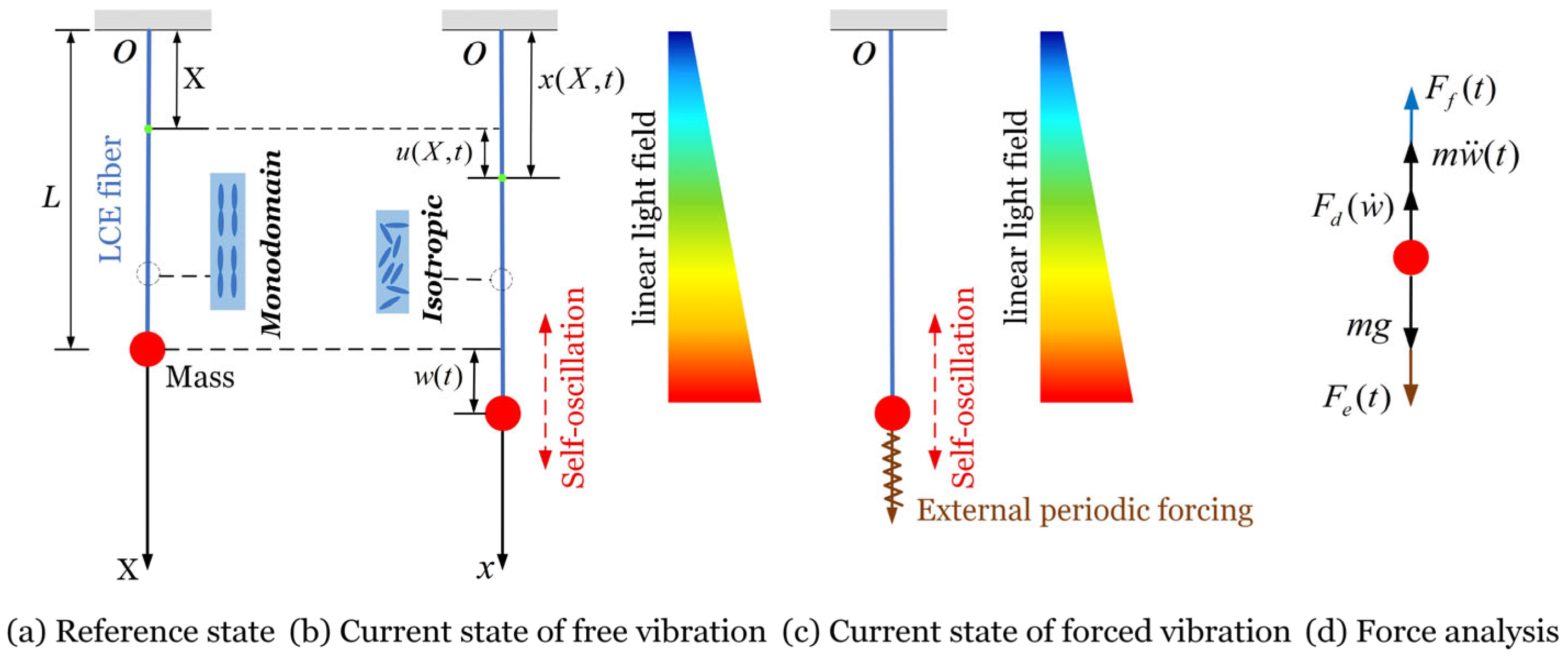
Figure 1. Schematics of a light-driven LCE self-oscillator under external periodic forcing. (a) Reference state. (b) Current state of free vibration. (c) Current state of forced vibration. (d) Force analysis. The self-oscillation occurs within a linear light field, and the external periodic forcing is applied to the LCE self-oscillator after entering the steady state.
Mathematics 13 03365 g001
Figure 2. Phase-locking regimes of the light-driven LCE self-oscillator under periodic forcing. In-phase synchronization: (a) Time variation curve for F ¯ e = 2 and ω ¯ = 2 . Quadrature synchronization: (b) Time variation curve for F ¯ e = 2 and ω ¯ = 3.4 . Anti-phase synchronization: (c) Time variation curve for F ¯ e = 2 and ω ¯ = 6 . The system parameters are K ¯ f = 10 , α ¯ = 0.3 , b ¯ = 1 , β ¯ 1 = 0.01 , β ¯ 2 = 0.05 , and τ ¯ = 0.01 . The initial conditions of w ¯ ( 0 ) = 0 and w ˙ ¯ ( 0 ) = 0 are set for the free vibration of the LCE self-oscillator. After entering the steady state, the external periodic forcing is applied with an initial phase difference of zero. The orange dashed vertical line indicates the moment when the external periodic forcing is applied.
Mathematics 13 03365 g002
Figure 3. Lissajous figures: (a) In-phase synchronization for F ¯ e = 2 and ω ¯ = 2 . (b) Quadrature synchronization for F ¯ e = 2 and ω ¯ = 3.4 . (c) Anti-phase synchronization for F ¯ e = 2 and ω ¯ = 6 .
Mathematics 13 03365 g003
Figure 4. Averaged wavelet power spectra: (a) Initial transient stage for F ¯ e = 2 and ω ¯ = 2 . (b) Late transient stage for F ¯ e = 2 and ω ¯ = 2 . (c) Steady state for F ¯ e = 2 and ω ¯ = 2 . (d) Initial transient stage for F ¯ e = 2 and ω ¯ = 3.4 . (e) Late transient stage for F ¯ e = 2 and ω ¯ = 3.4 . (f) Steady state for F ¯ e = 2 and ω ¯ = 3.4 . (g) Initial transient stage for F ¯ e = 2 and ω ¯ = 6 . (h) Late transient stage for F ¯ e = 2 and ω ¯ = 6 . (i) Steady state for F ¯ e = 2 and ω ¯ = 6 .
Mathematics 13 03365 g004
Figure 5. Phase trajectories and Poincaré points: (a) Initial transient stage for F ¯ e = 2 and ω ¯ = 2 . (b) Late transient stage for F ¯ e = 2 and ω ¯ = 2 . (c) Steady state for F ¯ e = 2 and ω ¯ = 2 . (d) Initial transient stage for F ¯ e = 2 and ω ¯ = 3.4 . (e) Late transient stage for F ¯ e = 2 and ω ¯ = 3.4 . (f) Steady state for F ¯ e = 2 and ω ¯ = 3.4 . (g) Initial transient stage for F ¯ e = 2 and ω ¯ = 6 . (h) Late transient stage for F ¯ e = 2 and ω ¯ = 6 . (i) Steady state for F ¯ e = 2 and ω ¯ = 6 .
Mathematics 13 03365 g005
Figure 6. Arnold tongue. The frequency of the LCE self-oscillator is locked to the forcing frequency within the gray V-shaped tongue, with the tongue tip located at the frequency ratio of ω ¯ / ω ¯ 0 = 1 : 1 .
Mathematics 13 03365 g006
Figure 7. Effect of forcing frequency on self-oscillatory response. (a) Effect of forcing frequency on response amplitude. (b) Effect of forcing frequency on phase difference.
Mathematics 13 03365 g007
Figure 8. Effect of forcing amplitude on self-oscillatory response. (a) Effect of forcing amplitude on response amplitude. (b) Effect of forcing amplitude on phase difference.
Mathematics 13 03365 g008
Figure 9. Regulation of self-oscillatory response by elastic coefficient of LCE fiber. (a) Regulation of response amplitude by elastic coefficient. (b) Regulation of phase difference by elastic coefficient.
Mathematics 13 03365 g009
Figure 10. Regulation of self-oscillatory response by thermal expansion coefficient. (a) Regulation of response amplitude by thermal expansion coefficient. (b) Regulation of phase difference by thermal expansion coefficient.
Mathematics 13 03365 g010
Figure 11. Regulation of self-oscillatory response by gradient of heat flux. (a) Regulation of response amplitude by gradient of heat flux. (b) Regulation of phase difference by gradient of heat flux.
Mathematics 13 03365 g011
Figure 12. Regulation of self-oscillatory response by first damping coefficient. (a) Regulation of response amplitude by first damping coefficient. (b) Regulation of phase difference by first damping coefficient.
Mathematics 13 03365 g012
Figure 13. Regulation of self-oscillatory response by second damping coefficient. (a) Regulation of response amplitude by second damping coefficient. (b) Regulation of phase difference by second damping coefficient.
Mathematics 13 03365 g013
Figure 14. Regulation of self-oscillatory response by thermal characteristic time. (a) Regulation of response amplitude by thermal characteristic time. (b) Regulation of phase difference by thermal characteristic time.
Mathematics 13 03365 g014
Table 1. Material properties and geometric parameters.
ParameterDefinitionValueUnit
L Original length of LCE fiber0.1m
K f Elastic coefficient of LCE fiber0~15N/m
m Mass of mass block0.01kg
g Gravitational acceleration9.8m/s2
α Thermal expansion coefficient−0.05~−0.011/°C
b Gradient of heat flux0~150°C/m
τ Thermal characteristic time0~0.2s
β 1 First damping coefficient0~0.004kg/s
β 2 Second damping coefficient0~0.02kg/s
Table 2. Dimensionless parameters.
Parameter α ¯ K ¯ f b ¯ β ¯ 1 β ¯ 2 τ ¯
Value−0.5~−0.10~150~1.50~0.040~0.20~0.02
Disclaimer/Publisher’s Note: The statements, opinions and data contained in all publications are solely those of the individual author(s) and contributor(s) and not of MDPI and/or the editor(s). MDPI and/or the editor(s) disclaim responsibility for any injury to people or property resulting from any ideas, methods, instructions or products referred to in the content.