1. Introduction
Ink trajectory. With the modernization of modern digital printing, research on the trajectory of the ink droplet movement remains relevant. The trajectory of droplets of inkjet, experiment, and modeling is given by Mohebi and Evans [
1]. They used a curve-fitting method to determine the drag coefficient for droplets (small size) in inkjet printing and to evaluate the velocity at exit. Considering the use of the application of inkjet printing, the analysis of the flying droplet and the prognosis of its landing on a non-flat substrate is given by Arango et al. [
2]. They mentioned that the density of the liquid affects the loss of the rate of falling droplets. In addition, the functional fluid’s use is limited due to physicochemical conditions forcing the Weber number (the range is not large) [
2]. Wang [
3] studied the aerodynamic influence on the location of the inkjet droplet and satellite. He mentioned that numerical modeling is a powerful tool in the study and development of an inkjet product. A study on the distribution of an electric field and the trajectory of droplets during electrohydrodynamic jet printing was given by Wu et al. [
4]. During research, based on the study of the distribution of the electric field, the analysis of the speed and direction of the ejected droplets was confirmed by plotting their trajectories. The movement of the droplets of ink in wide-format printers was investigated by Link et al. [
5]. They mentioned that, in accordance with the results, it is possible to significantly increase the relative movement of the head media without causing significant turbulence with the subsequent flow interference, which can worsen quality imprints. To examine the droplet ejection process for a piezoelectric (PZT) inkjet printhead, a numerical simulation model is presented by Yang [
6]. His presented theoretical model takes account of a set of three-dimensional, time-dependent conservation equations of mass and momentum, with the incorporation of the continuous surface force model for treating the interfacial surface tension effect. Inkjet printing technologies are presented by Hudd [
7]. He mentioned that the accuracy of placing the droplet depends on the exact position of the landing. Placement accuracy is uncertain due to various parameters, such as the nozzle and moistening of the surface, variations of the jet-to-jet, sensitivity to nozzle straightness, single jet-over-time, contamination of the nozzle plate, the condition and formulation, as well as the rate of the droplet. This problem is worse for longer flight paths or “throwing distance”.
Implementation/application of inkjet printing.
Manufacturers are increasingly utilizing inkjet printing technology due to its flexibility. Increasing demand for personalized production, such as small print run papers, souvenir production, textile printing, and even microchip manufacturing, meeting high-quality standards. Formalization and improvement of the design rules for inkjet printing are given by Mashayekhi et al. [
8]. For improving design rules and scaling down device dimensions, they present a design approach that combines pre-patterned, high-resolution substrates with digital inkjet fabrication as a demonstration of the capabilities of combining inkjet with other fabrication technologies. The cons and pros of inkjet technology in industrial inkjet printing are outlined in Zapka’s work [
9]. He also gave information on the comparison of inkjet and screen technologies.
Other implementation/application. There are many other implementations of the presented technology where ink can play an important role. Nowadays, trends in pharmaceutical and medical applications of inkjet printing technology are outlined by Skoutaris et al. [
10]. They noted that inkjet printing could help create drugs targeted to specific patient groups and could also be used in bioprinting in regenerative medicine to repair and replace damaged tissues as well as cells. Priyadarshini et al. [
11] presented 3D printing of biocompatible materials using Multi Jet Fusion technology for application in bioreactors. They noted that when using the concept as a bioreactor for Multi Jet Fusion (MJF) printed materials, it is necessary to support (given the MJF technology) not only cell proliferation and growth but also other highly regulated and complex processes, as an example osteogenesis.
Ink as material. A guide to printing inks is provided by Leach et al. [
12]. This guide contains all the information needed for the day-to-day development of printing inks and an understanding of this technique. The influence of ink types and printing processes on the efficiency of flotation deinking of recycled waste paper is presented by Nie et al. [
13]. They highlight the need for research to better understand the surface physical and chemical reactions of the ink/fiber system, particularly during the printing process for office waste, in order to optimize the flotation process for this material’s efficient recycling. The weight change in the inkjet droplets for the two-phase flow was investigated by Turkan [
14]. He performed Taguchi analysis and observed that the most effective parameter on ink weight was the inlet velocity. The fluid generation mechanism in a modified Continuous Inkjet Print (CIJ) method was investigated by Desai and Lovell [
15]. Given the complex drop formation mechanism, a computational fluid dynamics (CFD) model is developed that is further validated using an ultrahigh-speed photography experimental setup. The influence of solvent volatility on the reproducibility of droplet formation in inkjet printing in the pharmaceutical industry was described by Mau and Seitz [
16]. They noted that drop-on-demand (DoD) inkjet printing technology enables precise dosing and positioning of individual picoliter droplets.
Ink interaction. A study of the interaction of ink-paper using image analysis, volumetric inspection, and surface is presented by Fiadeiro et al. [
17]. Two optical systems and their implementation were demonstrated, which were used to perform bulk and surface monitoring of ink-paper interactions through image analysis.
Future. Future challenges and opportunities of inkjet technologies are given by Castrejón-Pita et al. [
18]. They noted that the technology needs consistent development to become widespread in new application areas such as additive manufacturing (3D printing).
This paper performs numerical simulation to analyze the different printhead horizontal moving velocities impact on the droplet form turnover during vertical fall, droplet shift, and droplet vertical movement velocities. Many known studies are mainly focused on the conditions of fixed printheads, Jiang and Tan [
19], Cadarso et al. [
20], and Wu et al. [
21]. With this condition, the movement of the drop does not depend on the moving print head. In this work, the movement of the print head is taken into account; this allows us to analyze the movement of the droplets not only in the vertical direction but also in the horizontal.
2. Problem Formulation
Printing velocity plays an important role in ensuring print quality. This velocity is determined by the movement of the printing head, which has a direct effect on the behavior of the ink droplets during printing (spray and fall of a droplet). Printing velocity and droplet deposition precision are the main objectives that every printer manufacturer tries to reach. During the contemporary challenges to high-quality printing without losing time, it is necessary to investigate moving inkjet printhead models numerically. The main challenge is to ensure the accuracy of precipitation/deposition of droplets on the surface as a fundamental factor of print quality.
During a numerical experiment with COMSOL software (software version 6.2; developer location: 100 District Avenue, Burlington, MA 01803, USA), it is important to accurately reproduce the printing head parameters, its movements, and the printing velocity. This must be conducted in the appropriate three-dimensional space. Only by following appropriate steps in a numerical experiment can one expect the results of a droplet trajectory, which is needed to determine the numerical results close to reality (physically). On the one hand, 3D modeling gives the ability to ensure a more realistic experiment, but on the other hand, it requires large computer resources. One of the tasks of the work was to choose the appropriate option/parameter for the mesh refinement, which was needed to properly determine and set the air–liquid interface. This is the essential task of the printing head movement during a droplet spray. The numerical experiment requires a higher number of finite elements and computer resources to calculate/achieve a printing head motion using a considered/appropriate theoretical model. It was also important to model/simulate the droplet spray/fall/deposition itself, which is important because if the droplet is not properly formed, it can form aerosol-type droplets or not spray at all. Therefore, it was important to determine and establish the correct initial parameters during the numerical experiment, which are necessary to reproduce physical printed droplets (size, movement, and behavior). However, despite the practical significance of numerical results in this work, important droplet dynamical motion parameters such as falling velocity, droplet shift displacement, and moving trajectory will be presented. The next section will present the methodology of a numerical experiment.
3. Methodology
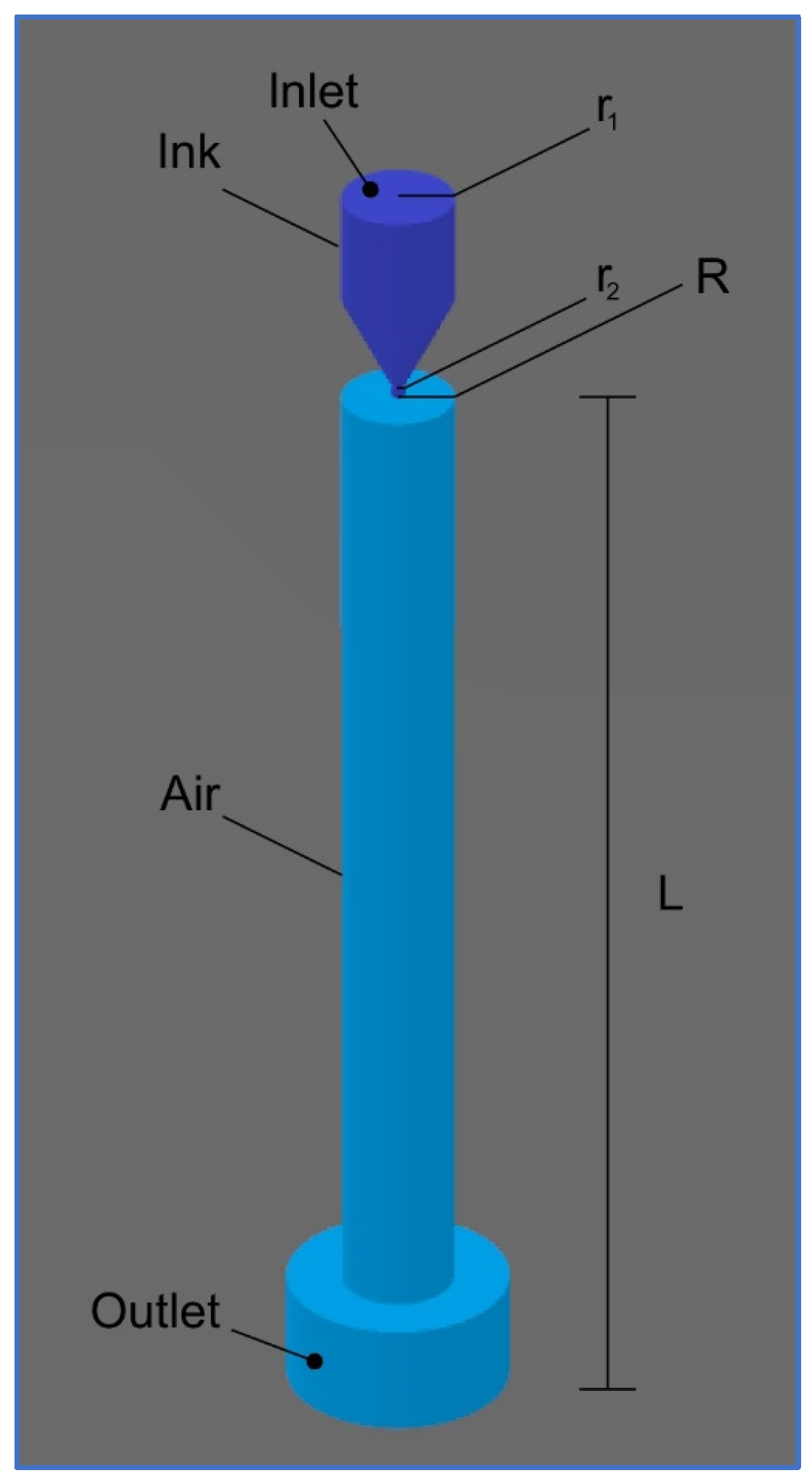
The single printhead ink chamber was modeled using COMSOL Multiphysics software (software version 6.2; developer location: 100 District Avenue, Burlington, MA 01803, USA). Inkjet printhead nozzle geometry dimensions are presented in
Figure 1.
A droplet is generated by applying fluid intake velocity to the inlet cross-sectional
to generate pressure inside the nozzle chamber (in
Figure 1 presented in dark blue color) and push inks through the nozzle cross-section
to the air-filled chamber (in
Figure 1 presented in light blue). The modeled air-filled cylindrical chamber has a radius
and distance to surface
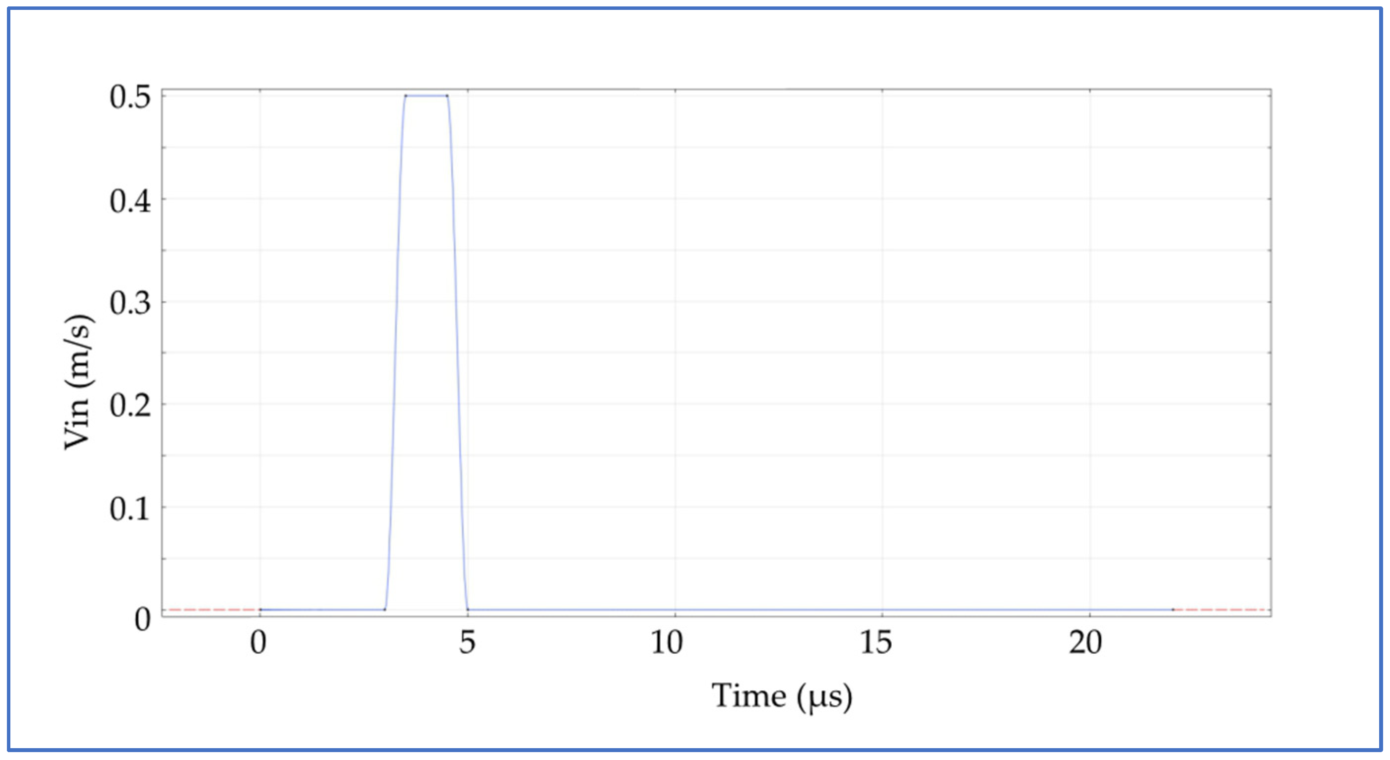
Constant pressure on the outlet has been set. The value of the pressure here is not directly important because the velocity depends only on the pressure gradient. On all other boundaries except the impact surface, there are set no-slip boundary conditions. The wetted wall boundary condition on the surface where the droplet falls off. Ink intake velocity and waveform dwelling time at the inlet are used to generate the pressure at the nozzle chamber. At the inlet, ink velocity increases from 0 to 0.5 m/s by the smooth parabolic profile actuated by an optimized waveform with a dwelling time of
The time-dependent velocity profile is defined in seconds and is a very smooth rectangular pulse function with the transition points at 3 μs and 5 μs with a 2 μs dwelling period at the peak (
Figure 2).
Additional ink is injected through the inlet during a period of 2 μs, and it consequently forces the ink to push out of the nozzle, forming the jet and transforming to the droplet furthermore. When the injection stops, a droplet of ink snaps off and continues to travel until it hits the surface.
The integration of the continuity equation and the Navier–Stokes equation in numerical simulations provides a coherent representation of incompressible substances two-phase flows. The formula used to calculate the continuity equation for an incompressible fluid is as follows:
Here, ∇ is the vector differential operator, and
u is the fluid velocity. From the definitions of calculus, we know that the gradient operator (∇) is calculated by the equation:
where
i,
j, and
k are the unit vectors in the directions of the x, y, and z coordinates.
The N–S equation describes the momentum conservation equation for a viscous, incompressible fluid in motion. This equation is written as follows:
Here, is the substance density; is the substance viscosity; is the pressure; is the acceleration due to gravity.
The following equation describes the interface between the ink and air phases. The convection of the reinitialized level set function is written as follows:
Here, the coefficient
represents the level set interface between ink and air, according to the COMSOL Module User’s Guide [
22]. Accordingly,
represents the air environment, and
represents ink. In the transition layer close to the interface,
smoothly changes from 0 to 1. Fluid velocity,
together represent the motion of the interface during the environment’s interplay. The parameter
determines the amount of stabilization of the level set function. A suitable value for
is the maximum magnitude occurring in the velocity field. Here, a time-dependent phase initialization approach is used. A numerical model for time-dependent two-phase flow requires an initialization of a level set function. By default, this reinitialization parameter
for the current simulation is set to
. Here ε refers to the thickness of the transition layer. For this simulation, ε is taken as half of the representative mesh size in the area that the falling droplet passes through. For this simulation, the interface thickness is controlled by default and set to 1.25 μm.
The Two-Phase Flow, Level Set Multiphysics coupling feature defines the density and dynamic viscosity of the fluid used in the Laminar Flow or Turbulent Flow interface, and it defines the surface tension on the interface in the form of a volume force used in the momentum equation. It also enables the Level Set interface to use the velocity field calculated from the Laminar Flow interface to transport the interface, according to the COMSOL Module User’s Guide [
22].
By defining the interface of different substrates, the level set function is used to stabilize the density and viscosity calculations through the interface. In numerical simulation, it is necessary to consider the dynamic viscosity (shear viscosity)
. It describes the interface between shear rate and shear stresses in the substrate. The substrate density and dynamic viscosity in different finite elements depend on the interface coefficient
. Density and dynamic viscosity are written as follows, Olsson and Kreiss [
23]:
In this instance, represents the density of air, while denotes the density of ink. Additionally, signifies the viscosity of air, and refers to the viscosity of ink.
The Navier–Stokes equations characterize the transfer of mass and momentum in an incompressible fluid, taking into account the effects of surface tension and gravitational forces. This research explores the ink and air substrates, analyzing how viscous stress develops at every point in the flow. The dynamics of the droplet, based on the conservation of mass, are derived from the subsequent differential equations, Sohr [
24]:
The force of surface tension can be determined using the equation provided below [
22]:
Here, δ is the Dirac delta function, σ is the surface tension coefficient, ĸ is the curvature, and n is the unit vector (normal direction). The calculation of the unit vector is derived from the equation below [
22]:
The delta function is approximated by the following equation [
22]:
This functionality will partition the simulation progress into several time intervals, facilitating localized mesh refinement in the areas where the ink and air interface is observed during each interval, thus increasing the accuracy of the computations. At the outset, our model consists of around 220,000 finite elements, and the mesh is refined 12 times during the droplet movement at the air substrate. During the second mesh refinement, the total count of finite elements increases to 800,000. As the number of finite elements increases, the average quality of the elements declines to 0.64. The mass of the final droplet can be determined using the equation provided below [
22]:
Several key dimensionless parameters significantly influence the working mechanism of the inkjet printhead. The Weber number (We) measures the ratio of inertia to surface tension, in contrast to the Reynolds number (Re), which serves to measure the ratio of a fluid’s inertia to its viscosity, Seipel et al. [
25]. The calculation of these dimensionless numbers is performed using the following equations:
Here, is the nozzle diameter, and is the droplet velocity.
The role of droplet velocity in the inkjet printing process can be predicted by the Ohnesorge number
. A solution derived from the Navier–Stokes equations exists for articulating the limitations of droplet ejection, taking into account the interfacial, viscous, and inertial characteristics of the fluid [
25]:
The calculation of the Oh value is based on the physical properties of the inks and the dimensions of the printhead nozzle. The dynamics of an expanding droplet emitted from a printhead nozzle are closely impacted by Oh value.
It is necessary to establish an initial specification for ink printability to ensure the ejection of stable form droplets, which should be maintained within the acceptable limits of 1 < Z < 10. (Fromm [
26]; Derby and Reis [
27]). If Z is greater than 10, the printing operation will generate satellite droplets, which will diminish the overall quality of the print. When Z is less than 1, the fluid’s viscous forces will obstruct the expansion of the droplet. The results comprise empirical data that are contained within numerical simulation calculations, which rely on the dimensionless numbers We, Re, and Z.
4. Experiment and Results
An appropriate combination of physical parameters is necessary for the printing process in a DoD inkjet printhead to work properly, which will also depend on the size and velocity of the droplets. The physical characteristics of the ink and air utilized in the numerical simulation of the inkjet printhead nozzle are detailed in
Table 1. Printing inks are described as Newtonian fluids for numerical calculations.
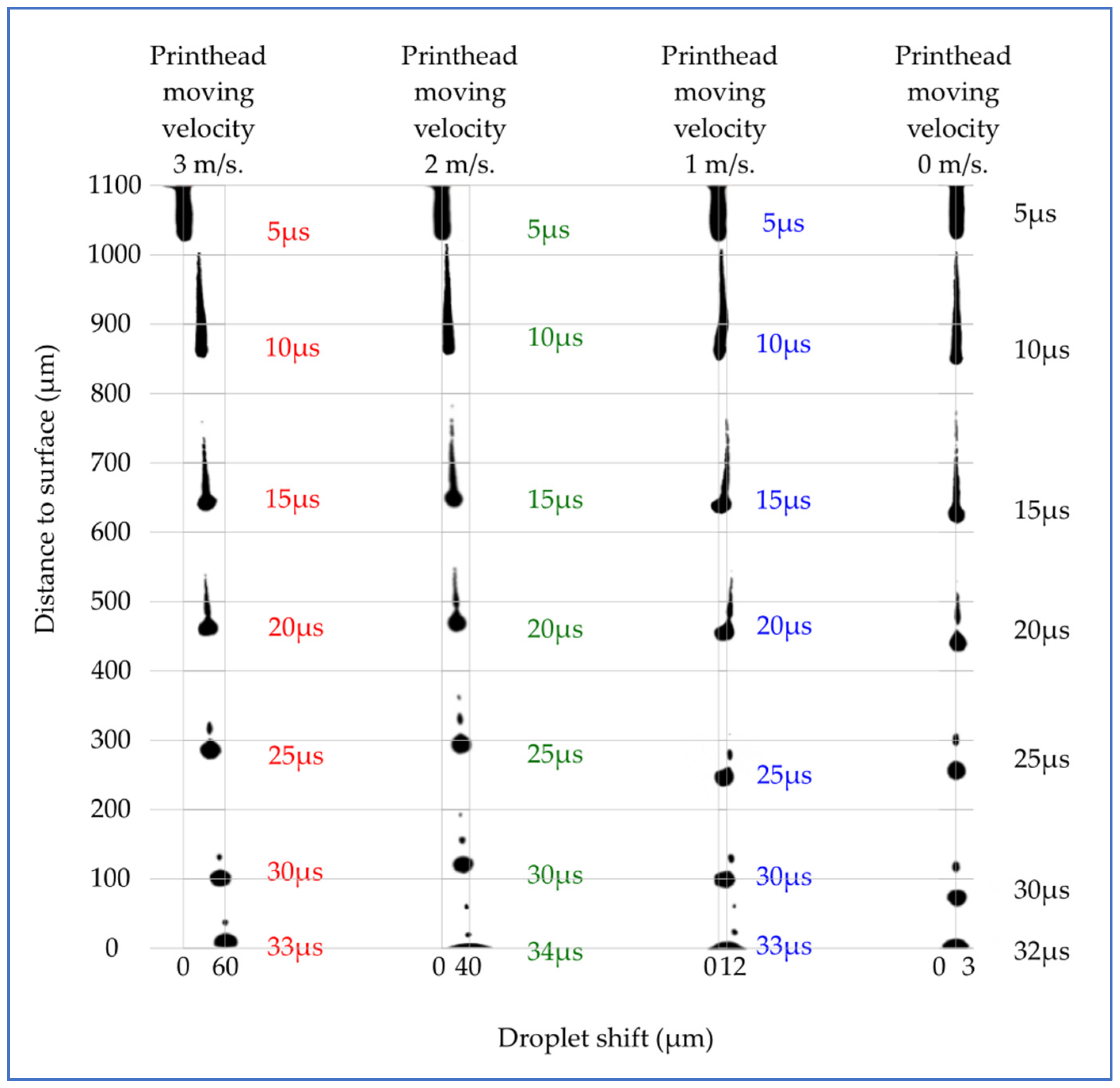
The form turnover in droplet ejection was achieved based on numerical simulations performed using COMSOL Multiphysics software. The presented graphs represent different horizontal printheads moving to the right side, with the different velocities (0 m/s, 1 m/s, 2 m/s, and 3 m/s) of the moving printhead shown in
Figure 3. Here, μs represent time from the ejection process start. The velocity u increases to a maximum at the beginning of the ejection process because droplet diameter increases immediately while ejecting, and droplet fluid takes the same velocity as printhead moving velocity. After the droplet pinches off from the printhead, it moves forward to the surface and changes form during free falling. The parasite satellites are formed from the droplet tail while the droplets form the spherical form. Then, the printhead is not moving, and the satellites are deposited in the center of the droplet impact place. When printhead motion in the horizontal direction is added, the droplet tail formation is different.
To measure the droplet, the shift from the start ejecting position to the final form on the surface is shown in
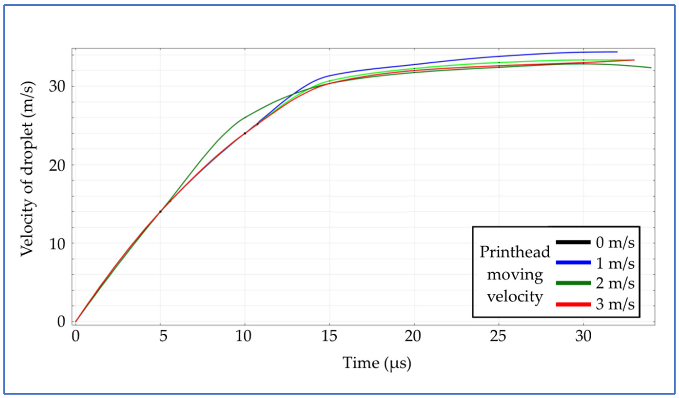
Figure 4. The investigation of droplet shifts by different printhead-moving velocities is represented. Simulation results represent how printhead moving velocity affects the deposition of the formatted droplet. The printhead horizontal move for 1 m/s impacts a 12 μm distance shift, 2 m/s–40 μm, 3 m/s–60 μm. All four ejected droplets reach the surface almost at the same time (±1 μs). There is visual graphic curvature turnover from 15 μs to 25 μs; at this period, the droplet jet tail unites with the main droplet mass and creates the sphere and some small malign satellites. Droplet vertical fall velocity also affects printing quality and droplet impact on the surface. Droplet movement velocity turnover during time is represented in
Figure 5.
The investigation of droplet vertical movement velocity is not affected much by different printhead moving velocities. That proves that different printhead moving velocities affected droplets reaching the surface almost at the same time (32–34 μs).
5. Conclusions
In this study, we investigated the effects of different moving printhead velocities on droplet formation processes and droplet falling trajectories. A 3D numerical model has been investigated that allows a detailed study of the trajectories of a droplet falling on a surface when spraying ink with different spray parameters and at different velocities of movement of the print head.
Figure 3 shows the turnover in the form of a droplet during vertical fall. The tail progress of the droplet is observed. The conversion of droplet satellites and the curvature of the droplet tail can be investigated. The droplet shift increases due to the increase in the movement velocity of the print head.
Figure 4 shows the curvature of the droplet shift trajectory in more detail. The main changes in the shift are observed with a time step from 15 μs to 25 μs. During this period, the droplet tail shrinks to the main body of the droplet, and it forms a sphere. The droplet deposition shift increases after this formation.
Figure 5 shows a stable increase in the droplet falling velocity till the 15 μs time step. After this step, the droplet tail starts to tighten up, which reduces the droplet’s falling velocity. The velocity of movement of the print head does not affect the droplet velocity in the falling phase. It is observed that the droplet falling motion at different printhead movement velocities does not have a stable trajectory. It depends on many parameters, such as the physical parameters of the ink, the geometric parameters of the printhead, the droplet ejection parameters, and the print head movement velocity, but the main changes are related to the droplet formation phases during the falling process.
The main result is the analysis of the trajectory and velocity of the droplet at each time step in the case when the printing head moves horizontally. Certain shifts affect the quality of the print when the droplets begin the ejection process and reach the surface. This shift increased due to an increase in the velocity of the inkjet printhead. As a rule, an inkjet printhead prints and moves in two directions (moving forward and backward), and in each print cycle, droplets should reach the same initially predicted place. The main advantage is to identify the effect of a shift on the movement of droplets, the accuracy of such a movement, and the numerical investigation of such a dynamic process itself. Many studies are limited by the vertical movement of droplets. Our investigation considers not only the vertical (normal direction) movement of droplets but also the horizontal (tangential direction) movement, taking into account the velocity and movement of a horizontally moving known physical printing head.
Considering what is mentioned above, further analysis is still needed, in which various printhead actuation/ejection parameters will be investigated.


