Article

Radio Frequency Fingerprint-Identification Learning Method Based-On LMMSE Channel Estimation for Internet of Vehicles

1
School of Internet of Things Engineering, Wuxi University, Wuxi 214105, China
2
School of Computer Science, School of Cyber Science and Engineering, Nanjing University of Information Science and Technology, Nanjing 210044, China
*
Author to whom correspondence should be addressed.
Mathematics 2025, 13(19), 3124; https://doi.org/10.3390/math13193124
Submission received: 2 September 2025 / Revised: 24 September 2025 / Accepted: 27 September 2025 / Published: 30 September 2025
(This article belongs to the Special Issue Machine Learning in Computational Complex Systems)

Abstract

As a typical representative of complex networks, the Internet of Vehicles (IoV) is more vulnerable to malicious attacks due to the mobility and complex environment of devices, which requires a secure and efficient authentication mechanism. Radio frequency fingerprinting (RFF) presents a novel research perspective for identity authentication within the IoV. However, as device fingerprint features are directly extracted from wireless signals, their stability is significantly affected by variations in the communication channel. Furthermore, the interplay between wireless channels and receiver noise can result in the distortion of the received signal, complicating the direct separation of the genuine features of the transmitted signals. To address these issues, this paper proposes a method for RFF extraction based on the physical sidelink broadcast channel (PSBCH). First, necessary preprocessing is performed on the signal. Subsequently, the wireless channel, which lacks genuine features, is estimated using linear minimum mean square error (LMMSE) techniques. Meanwhile, the previous statistical models of the channel and noise are incorporated into the analysis process to accurately capture the channel distortion caused by multipath effects and noise. Ultimately, the impact of the channel is mitigated through a channel-equalization operation to extract fingerprint features, and identification is carried out using a structurally optimized ShuffleNet V2 network. Based on a lightweight design, this network integrates an attention mechanism that enables the model to adaptively concentrate on the most distinguishable weak features in low signal-to-noise ratio (SNR) conditions, thereby enhancing the robustness of feature extraction. The experimental results show that in fixed and mobile scenarios with low SNR, the classification accuracy of the proposed method reaches 96.76% and 91.05%, respectively.

1. Introduction

With the rapid advancement of intelligent transportation systems, cellular vehicle-to-everything (C-V2X) has emerged as a pivotal technology in the fields of autonomous driving and smart transportation [1]. Based on cellular communication networks, C-V2X facilitates efficient information interaction between vehicles, vehicles and infrastructure, vehicles and pedestrians, as well as vehicles and networks, providing crucial support for traffic safety, efficiency and intelligence [2,3,4].
However, with the in-depth application of the IoV, the complexity of data transmission and the expansion of network scale have led to increasingly prominent security issues. Its broadcast characteristics are vulnerable to physical layer attacks, such as radio frequency interference and spoofing, as well as protocol vulnerabilities. For instance, the encryption mechanism in the EPS-AKA authentication scheme based on the international mobile subscriber identity and the universal subscriber identity module card is vulnerable to side-channel attacks and denial-of-service attacks [5,6]. The traditional cryptographic methods face the risk of being compromised, making it challenging to meet the high-security demands of the IoV [7]. RFF utilizes inherent hardware imperfections, such as I/Q imbalance and nonlinearity in power amplifiers, as unclonable physical identifiers. This approach not only circumvents issues related to computational complexity but also ensures that RFF possesses properties of forgery resistance and uniqueness, establishing it as an excellent medium for device identification and authentication [8,9].
Despite its advantages, the practical deployment of RFF faces substantial obstacles due to the dynamic and complex nature of wireless channel environments. Frequency-selective channels and time-varying channels make it difficult to directly extract pure and stable RFF features that are decoupled from channel characteristics, which results in poor identification performance in multi-path and mobile scenarios. Relevant experimental studies have shown that channel interference can directly cause the classification accuracy of Wi-Fi devices to decrease by up to 80% [10]. This issue is especially acute in multipath-rich scenarios typical of C-V2X applications. Consequently, the development of a channel-robust RFF-based identification mechanism is essential to enable secure and reliable C-V2X communications.
To this end, this paper introduces a PSBCH-based RFF identification method. It is specifically engineered to mitigate the detrimental impacts of wireless channel variations, thereby strengthening the physical layer security in C-V2X systems. The main contributions of this paper are as follows:
(1)
A novel RFF extraction method based on LMMSE channel estimation is proposed. This method optimizes the channel response estimation by combining the channel covariance matrix and noise statistical information and removes the channel response to generate initial fingerprint features, improving the robustness of fingerprint extraction in complex environments.
(2)
The ShuffleNet V2 network architecture is optimized for low SNR and dynamic channel conditions through the integration of an attention mechanism module. This approach can preserve high feature-extraction capabilities while maintaining a lightweight network, enhancing the model’s adaptability and generalization performance to ensure stable identification results.
(3)
During the training process, data collected from diverse scenarios is integrated to enhance the model’s generalization ability. By increasing the informational richness of the features, both computational load and the number of parameters are effectively reduced. This strategy improves computational efficiency while ensuring detection accuracy, thereby achieving a lightweight network. Experimental validation demonstrates the effectiveness of the proposed method, achieving classification accuracies of 96.76% and 91.05% in low-SNR stationery and mobile scenarios, respectively.
The remainder of this paper is organized as follows. Section 2 introduces the related work. Section 3 introduces the system model. Section 4 provides a detailed description of the signal preprocessing. Our proposed method is presented in Section 5. In Section 6, the effectiveness of the proposed method is validated through experiments. Finally, Section 7 concludes the paper.

2. Related Work

Existing research on mitigating channel effects in RFF can be broadly categorized into two main categories: the pursuit of channel-invariant features and methods that explicitly model or compensate for the channel. The first category focuses on maintaining both the wireless channel and data-transmission characteristics, aiming to mitigate distortion caused by channel variations and modulation data. The goal is to extract fingerprints that are inherently insensitive to these factors. Initial efforts focused on a transmitter’s transient features [11], like the signal’s turn-on and turn-off phases, as these segments are devoid of modulated data. However, transient-based methodologies impose stringent requirements on the operational environment and instrument precision, thereby suffering from poor replicability.
To overcome the limitations of transient features, several works utilize signal processing techniques to engineer features that are theoretically robust against channel variations. Some studies have proposed utilizing carrier frequency offset (CFO) as a device-identification feature [12,13]. However, CFO suffers from insufficient temporal stability and low inter-class separability. This makes reliable device classification difficult in multipath fading and multi-device scenarios [14]. In recent years, deep learning has propelled data-driven methods to the forefront of this research. Researchers attempt to automatically learn decoupled feature representations from data through complex neural networks. Tsipras proposed using adversarial examples as augmented data and constraining feature extractors through strong regularization [15], but this sacrifices model sensitivity and standard accuracy. Xie introduced a disentangled representation learning framework [16]. It separates device-specific features from channel-related components through adversarial training and signal decomposition to suppress overfitting to channel statistics. However, this could potentially discard subtle but critical RFF details. This vulnerability constrains the model’s ability to generalize when faced with complex and dynamic channel conditions.
The second technical category mainly addresses the impacts of data and the channel. Existing research has explored the use of data augmentation [17,18] and artificial noise injection [19] as strategies to mitigate channel interference. However, these methods have flaws. Data augmentation significantly increases training overhead. Artificial noise injections rely on a flawed linear assumption, creating a model mismatch. In addition, although systems such as Wi-Fi [20] and LoRa [21] can achieve channel compensation using protocol-specific frame structure features, their methodologies are limited by the heterogeneity of wireless communication standards. These methods cannot be directly migrated to the C-V2X system architecture. Other methods attempt to leverage channel reciprocity. for instance, the Quotient of the Estimated Channel State Information method [22] reduces channel effects by utilizing reciprocal Channel State Information. However, such approaches typically require the stacking of multiple consecutive frame samples from the same transmitter. This requirement is difficult to fulfill in many communication protocols.
In the field of Internet of Vehicles (C-V2X), many researchers focus on the pursuit of channel and data invariant characteristics. For example, Yin proposed a method for constructing differential constellation trajectory diagrams based on the transient characteristics of physical random-access channels [23]. It extracts the RFF features during the transient turn-on and turn-off phases using a multi-channel convolutional neural network. However, experiments have shown a significant degradation in classification accuracy for persistent symbol features like the demodulation reference signal (DMRS). Furthermore, as another approach to eliminate channel effects, Chen proposed the least squares (LS) method to directly remove the influence of the wireless channel through channel estimation [24], but this approach relies solely on pilot data, neglecting the characteristics of noise and the channel. In a low signal-to-noise ratio environment, noise is significantly amplified, leading to severe distortion in channel estimation [25].
Considering the limitations of the above-mentioned methods, we propose a feature-extraction method that utilizes LMMSE estimation and an attention-based deep learning model. A consolidated overview of the discussed methods and their trade-offs is presented for reference in Table 1.

3. System Overview

The system utilizes the PSBCH as the source for RFF extraction and is designed to perform device classification by leveraging the interplay between protocol-level structures and hardware-level features. This section primarily introduces the structure of the PSBCH format and the system framework.

3.1. PSBCH

In sidelink mode, the transmission technology for C-V2X is predominantly Single-Carrier Frequency Division Multiple Access (SC-FDMA). It supports six bandwidths: 1.4, 3, 5, 10, 15 and 20 MHz, corresponding to 1920, 3840, 7680, 11,520, 15,360 and 30,720 sample points, respectively. In this work, the maximum bandwidth mode is selected. In C-V2X communication scenarios, the peak relative velocity between terminals can reach up to 500 km/h, and the system operates in the 5.9 GHz frequency band. The combination of this high mobility and the high-frequency carrier results in a significant Doppler shift, which severely degrades both the accuracy of channel estimation and the stability of symbol synchronization. To mitigate these effects, the C-V2X protocol implements channel-adaptive optimizations within the PSBCH frame structure [26,27]. These optimizations include: (1) Pilot Enhancement: Three DMRS are inserted within each subframe at the 5th, 7th and 10th symbol positions to enhance time-varying channel tracking capabilities. (2) Guard Period (GP) Configuration: The 14th symbol is utilized as a redundant buffer against multipath delay spread to suppress Inter-Symbol Interference.
As shown in Figure 1 [26], a standard subframe is composed of two time slots, and the symbol allocation is as follows: the primary sidelink synchronization signal (PSSS) and secondary sidelink synchronization signal (SSSS) are configured at the 2nd–3rd and 12th–13th symbol positions, respectively, to achieve rapid time and frequency synchronization. The DMRS cluster, located at the 5th, 7th and 10th symbols, provides high-resolution channel state information. A GP is deployed at the 14th symbol to mitigate the effects of multipath delay spread. The remaining symbols are allocated for the PSBCH payload.

3.2. System Framework

The RFF investigated in this study is composed of various non-ideal characteristics of the transmitter’s hardware circuitry. These include the I/Q DC offset of the Digital-to-Analog Converter, frequency response deviations of filters and the non-linear distortion of the Power Amplifier. Collectively, these characteristics form a unique radio frequency fingerprint for each device.
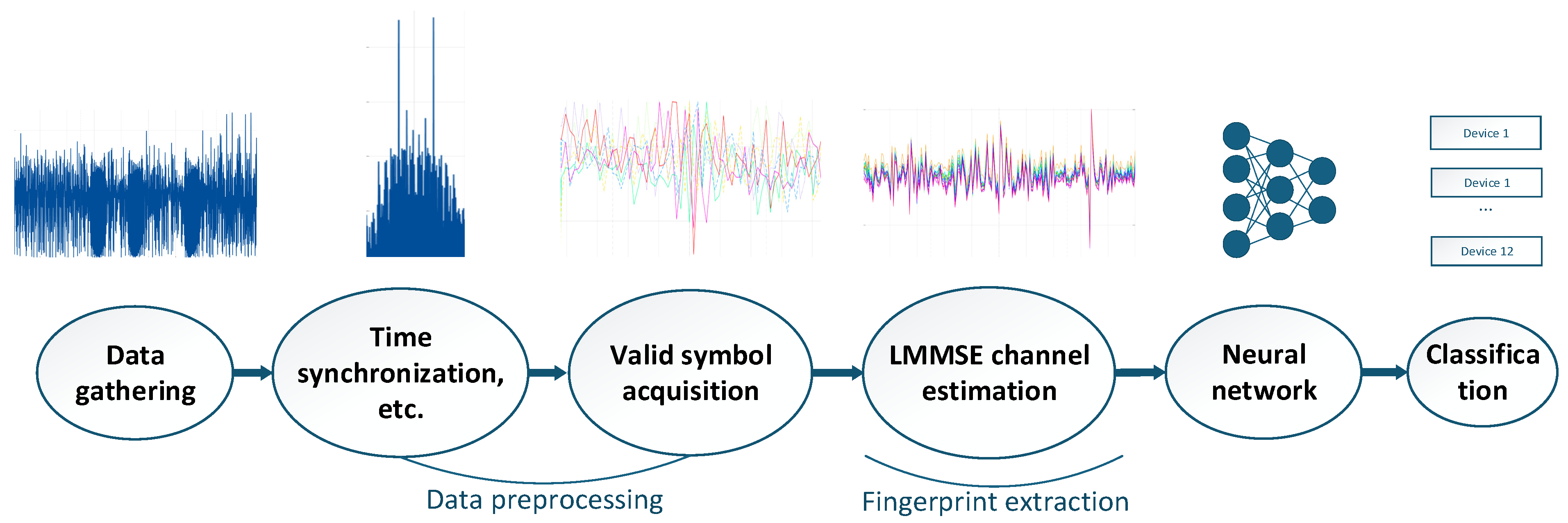
During signal transmission, a V2X terminal (such as an on-board unit, or a roadside unit) sends data to other devices over the wireless channel, with its inherent RFF features embedded within the transmitted signal. The system framework of the method proposed in this paper is illustrated in Figure 2. At the receiver, the signal first undergoes a preprocessing procedure, which includes signal acquisition and high-precision time synchronization. Based on the synchronization signals, a specifically designed algorithm is employed to extract the RFF features, while advanced signal processing techniques are used to effectively suppress interference from wireless channel fading and additive noise. Furthermore, this paper proposes a modified ShuffleNet V2-based neural network to per-form high-precision device classification.

4. Data Preprocessing

The signal preprocessing stage primarily includes signal detection, timing synchronization and CFO compensation.

4.1. Signal Detection

In the signal detection process, this paper employs a method based on block energy difference and thresholding to locate the signal’s starting point and subsequently utilizes a dynamic cropping strategy to determine the effective signal segment. The received signal y ( n ) , where n = 1 , 2 , , N corresponds to the length of the baseband signal, is partitioned into non-overlapping data segments of length W . The energy e ( k ) is then computed for each block:
e ( k ) = i = 1 w | y ( ( k 1 ) W + i ) | 2 = y k y k H
In equation, y k represents the k-th data block and i is the sample index. The onset of a signal typically manifests as a sharp increase in energy relative to the preceding noise floor. Therefore, we detect this jump by calculating the energy ratio between adjacent blocks. A signal energy jump is considered to have occurred at the beginning of the k-th block when the following condition is met:
e ( k ) e ( k 1 ) > T
where T is an empirically derived energy ratio threshold and T = 4 in this work. When the energy ratio between adjacent blocks exceeds a threshold, the starting point of the signal is identified as being in the vicinity of n 0 = ( k 1 ) W + 1 . This process thereby achieves the localization and detection of the target signal segment N .

4.2. Frame Synchronization

For the PSBCH signal, the Fast Fourier Transform (FFT) size is set to N F F T , with Cyclic Prefix (CP) lengths defined by the vector N g . In this configuration, the CP length for the 1st and 8th symbols is 160 samples, while for the remaining symbols, it is 144 samples, which conforms to the normal CP configuration for the sidelink. Coarse synchronization leverages the strong periodic properties of the PSSS symbol. A locally generated, standardized PSSS sequence S p s s s , is cross-correlated with the received signal using an amplitude-normalized operation to yield the correlation function R ( i ) :
R ( i ) = c o r ( | y ( i : i + L 1 ) | max ( | y ( i : i + L 1 ) | ) , | S p s s s | max ( | S p s s s | ) )
where L = N F F T + N g is the correlation window length. Subsequently, the two highest peaks of the correlation curve p 1 and p 2 are then located. A valid detection occurs if the interval between these peaks matches the known separation of the two PSSS symbols within a subframe. Next, fine synchronization based on the CP is performed to further refine the synchronization accuracy. A local search range is defined around the coarse synchronization point. The final synchronization point is determined by finding the offset Γ that maximizes the accumulated CP cross-correlation metric:
Γ = m = 1 M | c o r ( y ( i m : i m + N g ( m ) 1 ) , y ( i m + N F F T : i m + N F F T + N g ( m ) 1 ) ) |
where m is the OFDM symbol index and M is the total number of symbols over which the correlation is accumulated.

4.3. CFO Compensation

The CFO compensation process is divided into two stages: coarse compensation and fine compensation. First, coarse compensation is performed based on the synchronization symbols. Leveraging the repetitive nature of the two consecutive PSSS, which are identical, and likewise for the SSSS, the frequency offset is estimated using an autocorrelation method on the received signal [28]. This avoids the need to regenerate a reference sequence. The coarse frequency offset estimate Δ f s s s , is obtained by calculating the phase difference from the conjugate cross-correlation of the relevant signal segments:
Δ f s s s = f s 2 π N s s s arg { n = 0 N F F T 1 [ r 2 ( n ) r 3 * ( n ) ] + n = 0 N F F T 1 [ r 12 ( n ) r 13 * ( n ) ] }
where N s s s = N F F T + N C P = 2192 , which is the time interval (in samples) between the two repeated synchronization symbols, and r 2 , r 3 and r 12 , r 13 denote the correlation segments for the PSSS and SSSS, respectively. According to the principle of the autocorrelation frequency offset estimation algorithm [29], its unambiguous range is ± 1 / ( 2 T d e l a y ) , where T d e l a y = N s s s / f s . At a sampling rate of f s = 30.72   MHz , the theoretical successful capture range of the algorithm is approximately ± 7   KHz . Subsequently, fine compensation is performed based on the CP. By iterating over 13 symbols, the CP segment and the corresponding segment from the end of the symbol’s data portion are extracted. The phase difference is then calculated and averaged to obtain a high-precision frequency offset Δ f c p :
Δ f c p = f s 2 π N arg { m = 1 M i = 1 N g ( m ) [ r ( i + N s t a r t ( l ) ) r * ( i + N s t a r t ( l ) + N ) ] }
where N is the FFT size, N s t a r t is the FFT starting position and f s is the sampling rate. Finally, assuming the signal after timing synchronization is x ( n ) , the compensated signal r ( n ) is obtained through phase rotation:
r ( n ) = x ( n ) e j 2 π n Δ f n / f s
The total frequency offset estimate Δ f n is the sum of the course and fine estimates, i.e., Δ f n = Δ f s s s + Δ f c p .

4.4. Resource Grid Demodulation

Resource grid demodulation is a critical step for extracting the frequency-domain resource grid from the synchronized time-domain signal. Its performance influences subsequent channel estimation. For each symbol, the demodulation process is based on an FFT window starting time of N g ( m ) 0.55 , where the 0.55 factor ensures, the starting point is positioned in the middle of the Cyclic Prefix to minimize Inter-Symbol Interference. During demodulation, a time-domain sample segment of length N F F T is first extracted. This segment is then multiplied by a factor H F for half-subcarrier frequency offset compensation. Subsequently, an FFT is performed on the compensated time-domain signal to convert it to the frequency domain. To correct for the phase distortion introduced by the F s t a r t , the transformed frequency-domain signal is further multiplied by a phase compensation factor P C . Finally, the zero-frequency component is shifted to the center. The factors H F and P C are defined as:
H F ( i ) = e ( j π i N F F T ) P C ( i d x ) = e ( j 2 π N g ( m ) N s t a r t N F F T i d x )
where i d x is an index vector ranging from 0 to 2047. This method leverages the structural properties of the Cyclic Prefix and eliminates the effects of time-domain offsets and subcarrier misalignment through phase and half-subcarrier compensation, thereby yielding the frequency-domain resource grid.

5. Fingerprint Extraction and Classification

In the task of device identification, a critical challenge is how to effectively mitigate the influence of the channel while completely preserving the integrity of the RFF features. To this end, this section employs the LMMSE algorithm to perform channel compensation and extract the RFF features. Subsequently, these features are utilized to train a neural network to accomplish the final device-identification task.

5.1. Channel Estimation and Equalization

The channel-estimation process is conducted in three independent stages, targeting the PSSS, the SSSS and the DMRS, respectively. After preprocessing and CP removal, the received time-domain SC-FDMA symbols of the PSBCH are transformed into the frequency domain. By loading the predefined resource mapping, the LS estimation method provides an initial, coarse channel response by calculating the ratio of the received signal to the known reference sequences. Although the LS method is computationally simple, its accuracy is highly susceptible to noise and multipath effects, thus necessitating further optimization. In C-V2X systems, the Root Mean Square (RMS) delay spread is a critical parameter for channel estimation. It is particularly crucial for LMMSE-based channel estimation, where it is used to construct the channel autocorrelation matrix to enhance estimation accuracy. The RMS delay spread reflects the temporal dispersion of multipath components in the channel and directly influences its frequency-selective fading characteristics. The procedure for its estimation is detailed below.
First, the channel power σ h 2 is estimated to characterize the signal energy according to the formula:
σ h 2 = max ( 1 n N C i = 1 n N C | H L S ( i ) | 2 σ n 2 , 0 ) N C = 62 , C = 2 , 3 , 12 , 13 72 , C = 5 , 7 , 10
where, N c is the number of subcarriers occupied by the reference signal. The term H L S ( i ) represents the squared Frobenius norm of the LS channel estimates. For the PSSS, which occupies two symbols, this corresponds to a total of 124 subcarriers. σ n 2 is the input noise power estimate, which is calculated by averaging the energy over a known noise segment. The subtraction of the noise power can sometimes result in a negative value due to estimation errors. Therefore, a non-negative constraint is applied to ensure the stability of the final channel power estimate. The LS estimation results H L S are then averaged across the symbol dimension. Averaging the LS estimates over multiple symbols serves to suppress out noise and enhance the reliability of the channel response. Subsequently, a zero-padded inverse fast fourier transform (IFFT) is applied to the average frequency-domain channel response to convert it into the time-domain channel impulse response (CIR), which contains the amplitude and delay information of the multipath components. The zero-frequency position of CIR is adjusted to ensure delay alignment, and the Power Delay Profile (PDP) is calculated to provide the energy distribution of the multipath components:
P D P = | C I R | 2
The PDP represents the energy distribution of the multipath components. The zero-padding applied during the IFFT stage increases the resolution of the PDP, allowing for a more detailed analysis of the multipath structure. To mitigate interference from weak paths, a dynamic threshold ts is set based on the estimated signal-to-noise ratio SNRe to focus on the dominant paths:
t s = max ( P D P ) 10 max ( 5 , S N R e ) / 10
The threshold is obtained by converting the dB value to a linear scale and multiplying it by the maximum value of the PDP. The max ( 5 , S N R e ) ensures a minimum attenuation, preventing the threshold from becoming excessively high in low-SNR conditions. Subsequently, the Power Delay Profile is normalized to transform it into a probability distribution, which facilitates the statistical analysis of delay characteristics. Assuming a delay vector τ , it is defined as:
τ ( i ) = i T s ( i = 0 , 1 , , N C 1 )
where T s = 1 / ( N c Δ f ) is the time-domain sampling period and Δ f = 15   kHz is the subcarrier spacing. The RMS delay spread τ r m s is defined as the root mean square deviation of the delay and is calculated using the following formula:
μ τ = i = 0 N C 1 P D P ( i ) τ ( i ) τ r m s = i = 0 N C 1 P D P ( i ) ( τ ( i ) μ τ ) 2
where μ τ is the mean delay, which is the expected value of the delay based on the Power Delay Profile.
The construction of the channel autocorrelation matrix R H H is based on the Root Mean Square delay spread and is finally defined as:
R H H ( p , q ) = σ h 2 1 1 + j 2 π ( p q ) Δ f τ r m s ( p , q = 1 , 2 , , N C )
Here, ( p q ) Δ f represents the frequency difference between pairs of subcarriers. Multiplying it by 2 π τ r m s yields the phase offset associated with the delay spread. This formulation models the channel’s frequency correlation, simulating induced by multipath channels. To eliminate numerical errors introduced during computation, the matrix R H H is adjusted to enforce Hermitian symmetry by averaging the original matrix with its conjugate transpose. This procedure ensures the matrix remains positive semi-definite. Given that the channel-estimation process in the IoV environment is highly susceptible to noise and multipath effects—particularly under low SNR or complex channel conditions where estimation accuracy can degrade significantly—an a priori SNR S N R p , derived from the correlation matrix R H H , is introduced to optimize the LMMSE estimation. By integrating channel correlation and delay information, S N R p reflects more accurate channel statistical properties:
S N R p = t r a c e ( R H H ) / N c σ n 2
A dynamic regularization term λ is then generated based on SNR_prior. When S N R p is high, the influence of regularization is reduced to preserve channel details. Conversely, when S N R p is low, the regularization strength is increased to enhance matrix stability. The frequency-domain channel estimate for the i-th symbol is then calculated using the following equation:
W = R H H ( R H H + σ n 2 I ( N C ) ) 1 H L M = W H L S
W is the LMMSE weighting matrix, which utilizes channel correlation to correct for noise and systematic errors in the LS estimate, thereby enhancing estimation accuracy. In multipath channels, the Channel Impulse Response (CIR) is typically concentrated on a few samples in the time domain, a characteristic related to the RMS delay spread. In C-V2X, typical values for this spread range from 0.1 to 5 microseconds, reflecting the transient nature of multipath components in urban or highway environments. In contrast, noise and radio frequency interference are more broadly distributed across the time domain and do not exhibit the concentrated nature of the CIR. Consequently, the obtained frequency-domain channel estimate H L M can be further refined. By transforming it into the time domain via an Inverse Discrete Fourier Transform and applying a windowing operation, the widespread noise components can be effectively removed. This process yields a more accurate channel estimate because the noise components are suppressed while the principal multipath components of the channel are preserved. Finally, the windowed time-domain estimate is transformed back into the frequency domain using a Discrete Fourier Transform to obtain the final frequency-domain estimate. In low- to medium-speed vehicular scenarios, the channel transformation experienced by adjacent symbols is minimal. Therefore, the frequency-domain estimates of adjacent symbols can be considered approximately identical. By averaging these estimates, the redundancy of the reference signals is leveraged to smooth out noise and interference, yielding the final frequency-domain channel estimate.
The initial RFF is then extracted by removing the channel information through equalization. Let the received signal for the C-th frequency-domain SC-FDMA symbol, after preprocessing, CP removal and DFT, be denoted as Y C ( k ) . The specific channel-equalization operation is as follows:
R ( i ) = Y ( i ) H L M ( i )
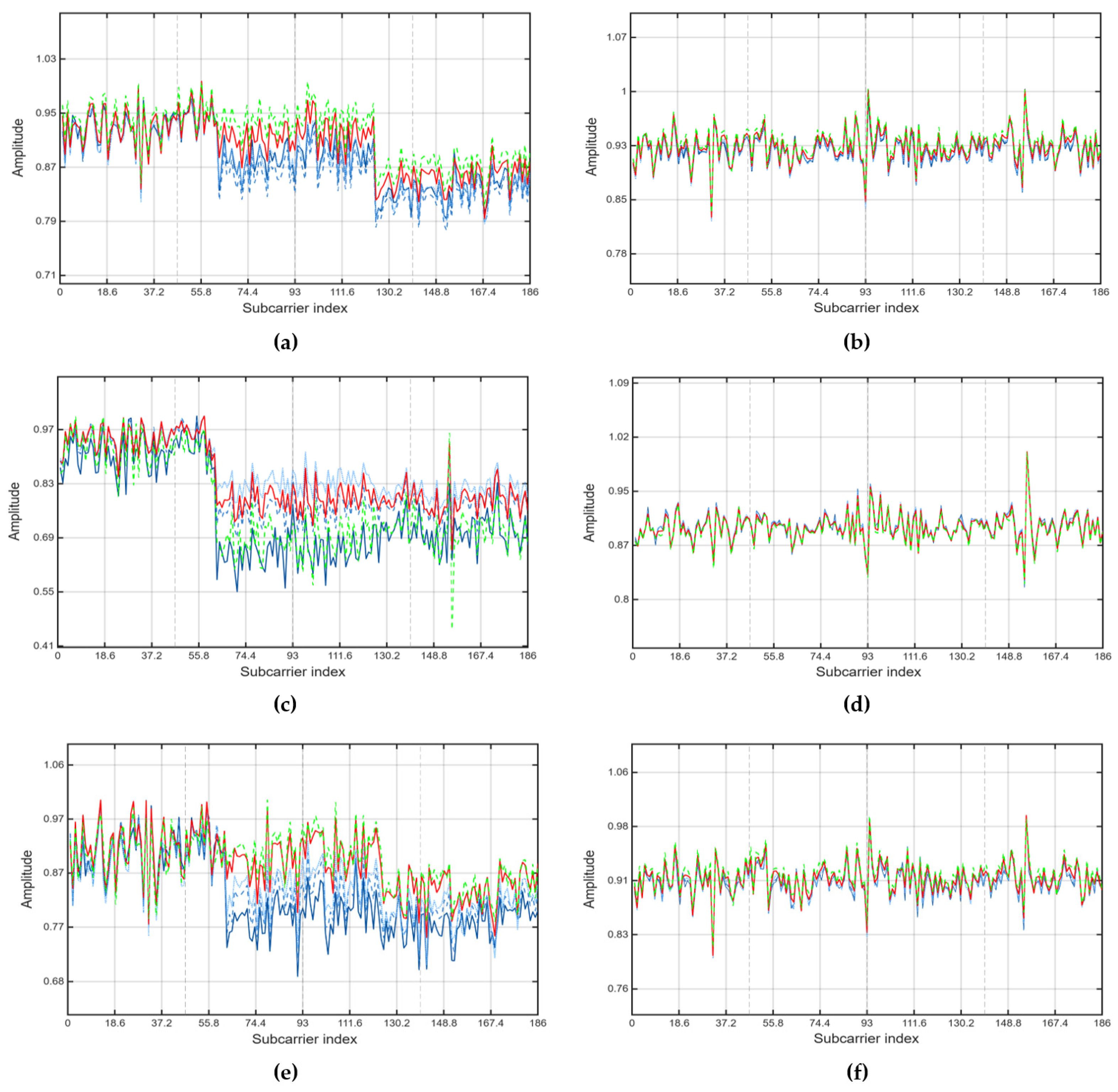
Furthermore, the initial RFFs corresponding to the same data sequence can be further averaged and subsequently used for identification in the proposed network. Figure 3 shows the comparison of subframes before and after channel processing.

5.2. Improved ShuffleNet V2 Network

In C-V2X systems, RFF identification technology provides a critical safeguard for secure vehicular communications by leveraging physical layer characteristics for device authentication. The performance of RFF identification is highly dependent on the quality of feature extraction and the effectiveness of the classification model. ShuffleNet V2 [30] inherits the lightweight design philosophy of its predecessor, ShuffleNet V1 [31] and constructs a novel network architecture based on four principles for efficient network design. These principles include: (1) maintaining an equal number of input and output channels in convolutional layers to optimize computational speed; (2) balancing the use of group convolutions, which increase memory access overhead and reduce efficiency; (3) simplifying network branching, as an increased number of branches can degrade performance; and (4) reducing element-wise operations, which are computationally expensive. These design principles ensure that ShuffleNet V2 achieves high computational efficiency within a lightweight framework, making it suitable for resource-constrained scenarios such as on-board vehicular units and embedded systems. However, the original ShuffleNet V2 was designed for two-dimensional image classification. When directly applied to the RFF identification task in C-V2X systems, which involves processing one-dimensional frequency-domain signals, it exhibits limitations such as an insufficient capacity for capturing frequency-domain features and a lack of task-specific optimization. To address these issues, this section proposes a series of targeted improvements, including adjustments to the channel and layer structures and the integration of an attention mechanism.

5.2.1. Network Architecture Design

The Inverted Residual module is the core component of ShuffleNet V2, used to construct the various stages of the network. This module employs an inverted bottleneck structure: it first increases the number of channels in an expansion phase using a pointwise convolution, then utilizes a depthwise separable convolution to extract frequency-specific features from the one-dimensional (1D) frequency-domain data and finally reduces computational complexity through another pointwise convolution in a linear bottleneck layer.
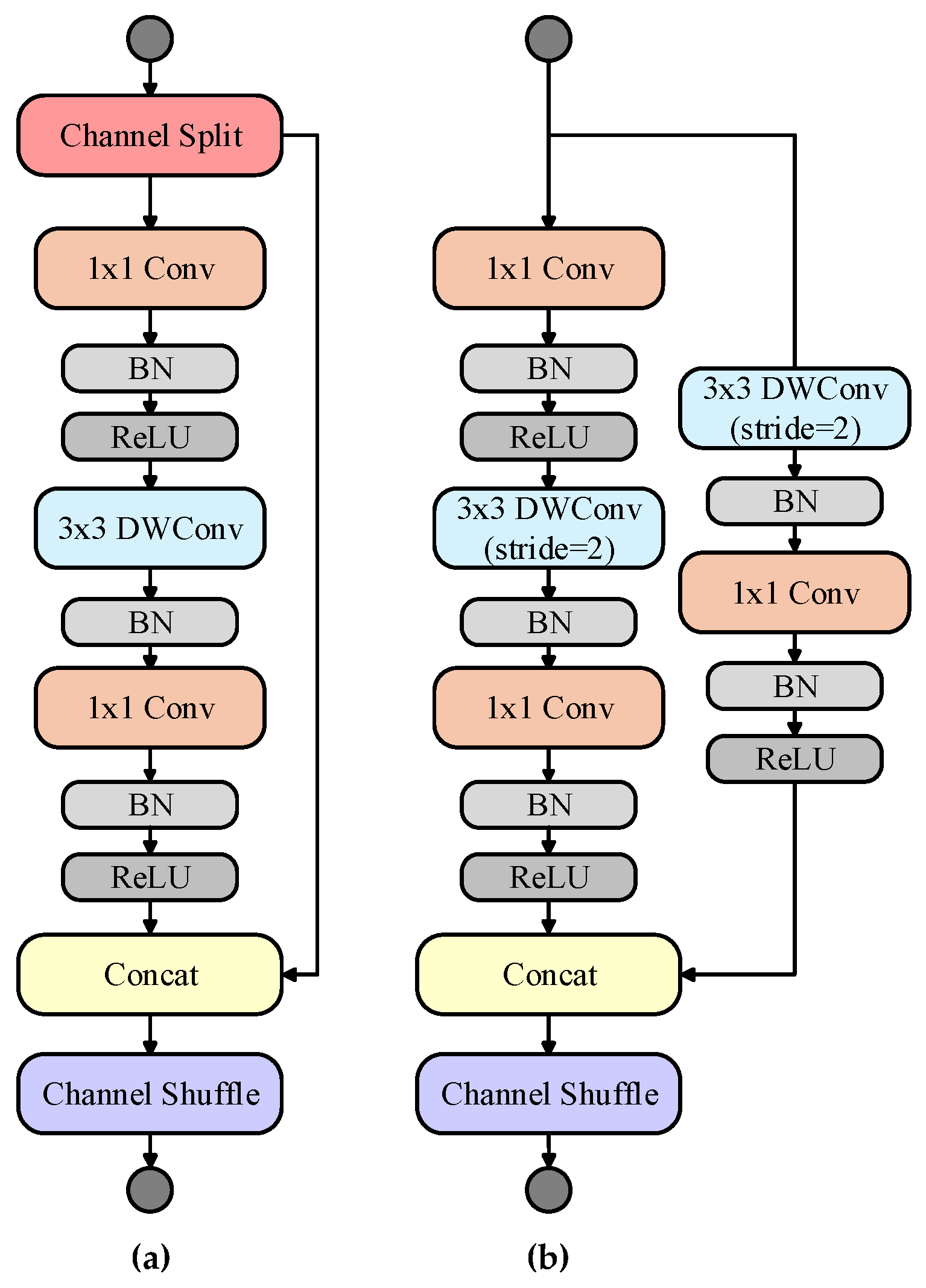
As illustrated in Figure 4, for the case where stride = 1, a channel split operation is used to reduce computational load while an identity mapping is retained to support the residual connection. For the case where stride = 2, two separate branches are employed to process the feature dimensions and increase the number of channels. Considering that the extracted RFF signal is 1D frequency-domain data, the network’s computational units have been adapted to a 1D configuration to facilitate feature extraction along the frequency axis. This allows the model to directly learn and model the correlations between frequency points.
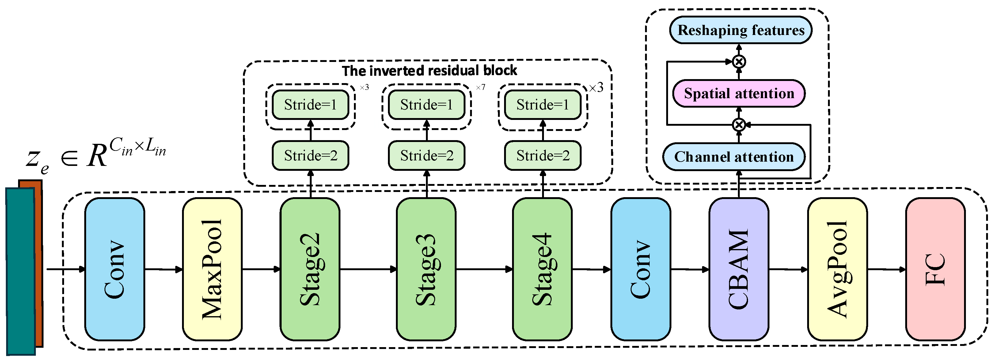
Regarding the adjustments to the channel and layer structure, as shown in Figure 5, the number of blocks in Stage 2 was set to 4 with 116 output channels, and the number of blocks in Stage 3 was set to 8 with 232 output channels. This modified network structure enhances the ability to extract deep patterns from frequency-domain signals, making it particularly suitable for capturing the subtle spectral differences between devices. The channel adjustments increase feature diversity, enabling the network to represent a wider range of potential frequency-domain features. Stage 4 was maintained with 1024 channels to strike a balance between representational power and computational cost.
The channel shuffle operation from ShuffleNet V2 is retained to facilitate efficient feature fusion and mitigate the information isolation caused by group convolutions. Let B be the batch size, G the number of groups, C the number of channels and L the signal length. When shuffling along the channel dimension, the specific dimensional transformation process is as follows:
x = Reshape ( x , [ B , G , C G , L ] ) Transpose ( x , [ 1 , 2 ] ) Flatten ( x , [ B , C , L ] )

5.2.2. Attention Mechanism

To enhance the network’s ability to focus on the frequency-domain features that are crucial for RFF identification, we integrate a convolutional block attention module (CBAM) [32] after the final convolutional layer. CBAM combines channel attention (CA) and spatial attention (SA) to adaptively adjust feature weights, thereby highlighting key spectral characteristics. Its implementation is detailed below.
The CA module, as illustrated in Figure 6, extracts channel-wise features through both global average pooling and global max pooling. These features are then processed by fully connected layers to generate channel weights. The operation is expressed by the following formula:
C A ( X ) = σ ( W 2 ReLu ( W 1 ( GAP ( X ) + GMP ( X ) ) ) )
where X is the input feature, G A P and G M P represent global average pooling and global max pooling, respectively. The features are processed through two fully connected layers for dimensionality reduction and subsequent restoration: a dimensionality-reduction layer W 1 reduces computational complexity, and a dimensionality-restoration layer W 2 restores the channel dimension. σ denotes the sigmoid activation function.
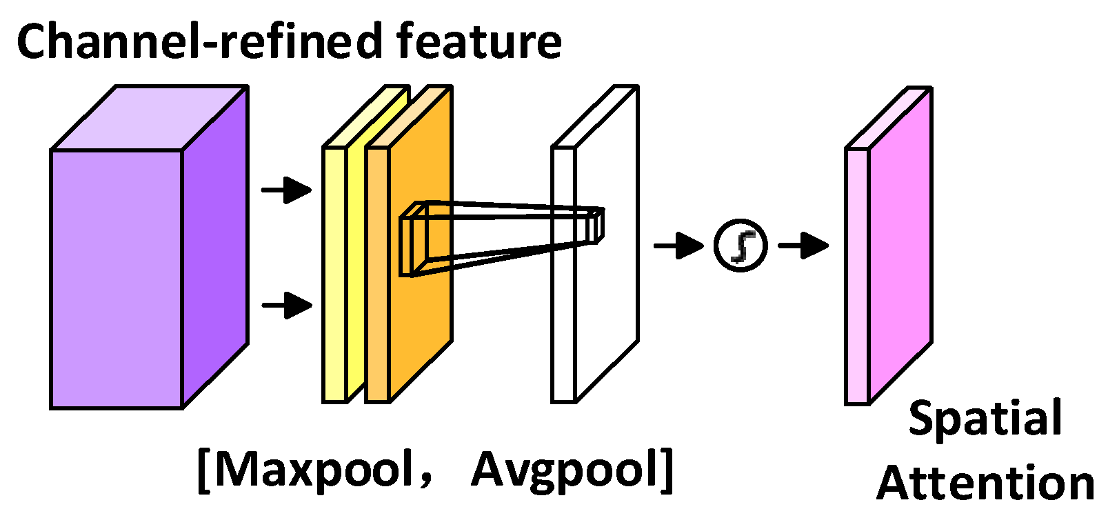
The SA module, as illustrated in Figure 7, models the one-dimensional spatial structure of the feature maps to focus on critical regions while suppressing noise and redundant information. Operating on the feature maps that have been weighted by the channel attention module, spatial features are generated by applying average pooling and max pooling along the channel dimension. A one-dimensional convolution is then utilized to generate the spatial weights, as expressed by the following formula:
S A ( X ) = σ ( Conv 1 D ( Concat ( Mean ( X , 1 ) , Max ( X , 1 ) ) ) ) X o u t = X C A ( X ) S A ( X )
The input X is sequentially weighted by C A and S A to produce the final output X o u t . Through this joint optimization across both channel and spatial dimensions, the CBAM module enables the network to dynamically focus on the critical spectral features within the RFF signal.

6. Results and Discussion

6.1. Experimental Environment

The experiment utilized twelve identical C-V2X modules for PSBCH subframe transmission across a 20 MHz bandwidth. Signal reception was handled by a Universal Software Radio Peripheral (USRP) B205mini-i (Ettus Research, Austin, TX, USA), configured with a 5.9 GHz carrier frequency and a 30.72 Msps sampling rate. Our data collection encompassed a diverse range of environments. a direct-connection setup, stationary Line-of-Sight (LOS) and Non-Line-of-Sight (NLOS) scenarios, and three mobile scenarios. These mobile scenarios included MOV1 (LOS), MOV2 (NLOS) and MOV3 (a blend of LOS and NLOS conditions). Throughout the collection process, transmitted PSBCH subframes were randomized. We captured approximately 1000 subframes from each device in every scenario. Following preprocessing and fingerprint extraction, the final fingerprint features used for classification are complex vectors, with their dimensionality corresponding to the number of effective subcarriers occupied by the PSBCH, these captured subframes formed the training and testing datasets. All models were implemented in Python 3.12 and trained for approximately 100 epochs. The model demonstrating the best performance was subsequently selected for the final testing phase.

6.2. Evaluation Criteria

Overall Accuracy, the primary evaluation metric, measures the proportion of correctly classified device fingerprint samples. In addition, the macro-F1 score, which is the harmonic mean of precision and recall, is employed to assess the balanced performance of the model across all classes.
A c c u r a c y = i = 1 N T P i i = 1 N ( T P i + F N i ) M a c r o - R e c a l l = 1 N i = 1 N R e c a l l i = 1 N i = 1 N T P i T P i + F N i M a c r o - P r e c i s i o n = 1 N i = 1 N P r e c i s i o n i = 1 N i = 1 N T P i T P i + F P i M a c r o - F 1 = 1 N i = 1 N 2 P r e c i s i o n i R e c a l l i P r e c i s i o n i + R e c a l l
In the equations above, T P i represents the number of true positives for a specific class i , that is, samples that actually belong to class i and are correctly classified as such by the model. F P i is the number of false positives, representing samples that do not belong to class i but are incorrectly classified as i . F N i is the number of false negatives, denoting samples that belong to class i but are incorrectly classified as another class. Finally, T N i represents the total number of true negatives, which are samples that do not belong to class i and are correctly predicted by the model as not belonging to class i .

6.3. Experimental Results and Discussion

6.3.1. Classification Under Different SNR

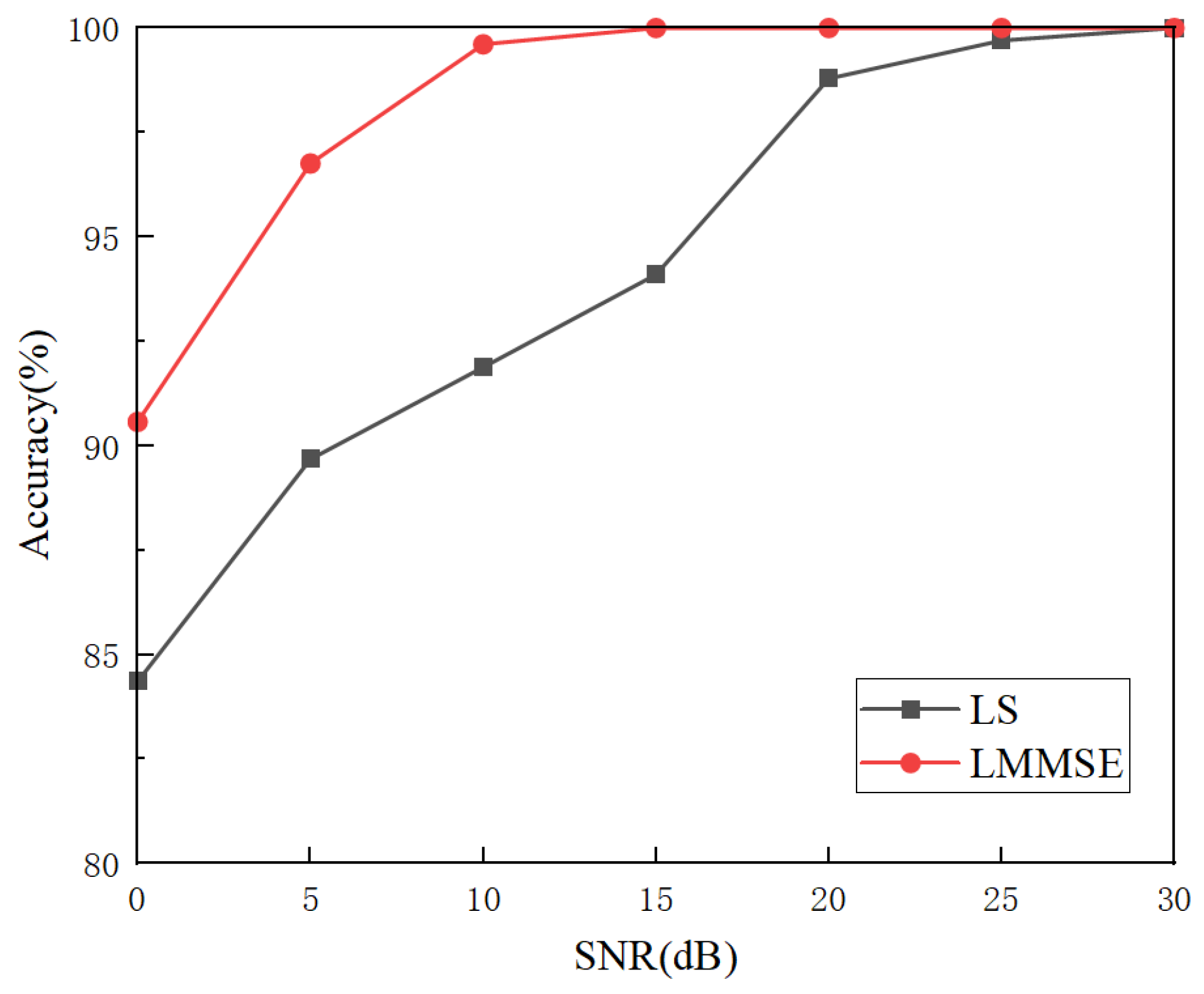
This section analyzes the accuracy of two channel-estimation methods under varying SNR conditions. As shown in Figure 8, which illustrates the trend in identification accuracy over an SNR range from 0 dB to 30 dB, the accuracy of both methods exhibits an upward trend as the SNR increases. In the low-SNR region (0–10 dB), the accuracy of the LS method is comparatively low, starting from a lower initial value and increasing slowly, which reflects its limited capability for noise suppression. In contrast, the LMMSE method effectively suppresses noise interference at low SNRs by leveraging information about the channel’s autocorrelation and noise variance. At SNRs below 5 dB, its accuracy remains above 90%, and its performance increases more steadily, demonstrating its superior robustness under low-SNR conditions. At high SNRs (above 20 dB), both methods achieve near-perfect accuracy. Nevertheless, the LMMSE method consistently maintains a slight performance advantage, confirming its robustness even in favorable channel conditions.

6.3.2. Classification in Different Scenarios

As shown in Table 2, which presents the cross-authentication results of the fingerprints extracted after the proposed LMMSE channel estimation on a multi-scenario test set, high classification accuracy was achieved, with a maximum of 100% and a minimum of 95.64%. The experimental results indicate that the composition of the training set has a significant impact on the classification performance on the test sets. Taking the Direct-connection (DC) scenario as an example, when the training set consisted solely of DC data, the cross-authentication accuracies on the LOS, NLOS and mobile scenarios (MOV1, MOV2, MOV3) were 99.75%, 98.82%, 99.01%, 98.09% and 99.59%, respectively. However, when the training set was expanded to a combination of direct-connection and NLOS data, the accuracy on the MOV1 scenario reached 99.89%, while the accuracy on the direct-connection scenario decreased to 95.64%. This is attributed to the fact that the multipath effects in the NLOS scenario enhance the distinctiveness of the fingerprints, whereas the channel uniformity in the direct-connection scenario reduces feature diversity after equalization. Furthermore, because the collection locations in the stationary scenarios are identical, the resulting consistent channel conditions can lead to fingerprints that are less distinctive after channel equalization. Consequently, the superior results of mobile scenes in some cross-scenario tests can be attributed to their greater channel variation compared to the more uniform conditions of stationary scenes. Overall, however, the combination of different training sets has a marked impact on classification performance.

6.3.3. Comparison of Different Models

To evaluate the generalizability of the proposed method to other deep learning architectures, a comparative analysis was conducted against several models, including DenseNet, MobileNet, EfficientNet, MobileViT, ConvNeXt and the original ShuffleNet V2. Table 3 summarizes the performance of each model in the mobile scenario. The proposed model achieved an overall accuracy of 99.01% and demonstrated superior performance in terms of macro-precision and macro-F1 score, outperforming the other models. The improved channel estimation provides the model with more precise device fingerprint features, while the integration of the computationally efficient CBAM attention mechanism enhances the model’s ability to focus on discriminative features, particularly in the environment of the mobile scenario. In contrast, although DenseNet and MobileNet offer advantages in computational efficiency, their lower precision and F1 scores indicate limitations in processing the multi-scenario fingerprint dataset. It is noteworthy that most existing models rely on offline training. However, discrepancies between offline and live data, which can arise from factors such as device aging, often lead to performance degradation in practical applications. The lightweight nature of our proposed model makes on-site training and fine-tuning a feasible solution to this challenge.

6.3.4. Model-Authentication Performance Evaluation

To evaluate our model, we designed an experiment for device authentication in an open environment. This experiment tests the model’s generalization and robustness on new, untrained devices.
(1)
Experimental Setup
We used data from nine devices (CX1 to CX9) to train our network model. This process aims to help the model learn a compact and representative feature space. In this space, signal features from the same device are clustered together. The test set includes entirely new data from all twelve devices (CX1 to CX12). These data were not seen during the training phase. Among them, three devices (CX10, CX11, CX12) are unknown devices. To evaluate authentication performance, we constructed sample pairs from the test set. These pairs were divided into two categories. The first is genuine pairs, where both signal samples in a pair come from the same known, legitimate device. The second is imposter pairs. These include two scenarios: pairs from two different known devices, and pairs with one known and one unknown device. The second scenario simulates an unknown device attack.
(2)
Authentication Method
Our authentication process is based on metric learning in the feature space. For each signal sample, the trained model first maps it to an N-dimensional feature vector. Subsequently, for a sample pair ( v 1 , v 2 ) to be verified, we measure their similarity by calculating the Euclidean distance, d, between their feature vectors:
d i = D ( v 1 , v 2 ) = j = 1 N ( v 1 , j v 2 , j ) 2
where N = 128 is the dimension of the feature vector. The calculated distance d is then compared with an adjustable decision threshold τ . If d τ , the system determines the device is legitimate. If d > τ , the system determines the device is unknown.
(3)
Performance Metrics
By varying the decision threshold τ across all sample pairs in the test set, we calculate two key performance metrics. One is the False Acceptance Rate (FAR). It is the probability of the system incorrectly identifying an imposter pair as genuine.
FAR ( τ ) = P ( d τ | Imporster )
The other is the False Rejection Rate (FRR). This is the probability of the system incorrectly identifying a genuine pair as an imposter.
FRR ( τ ) = P ( d > τ | Genuine )
(4)
Evaluation Criteria
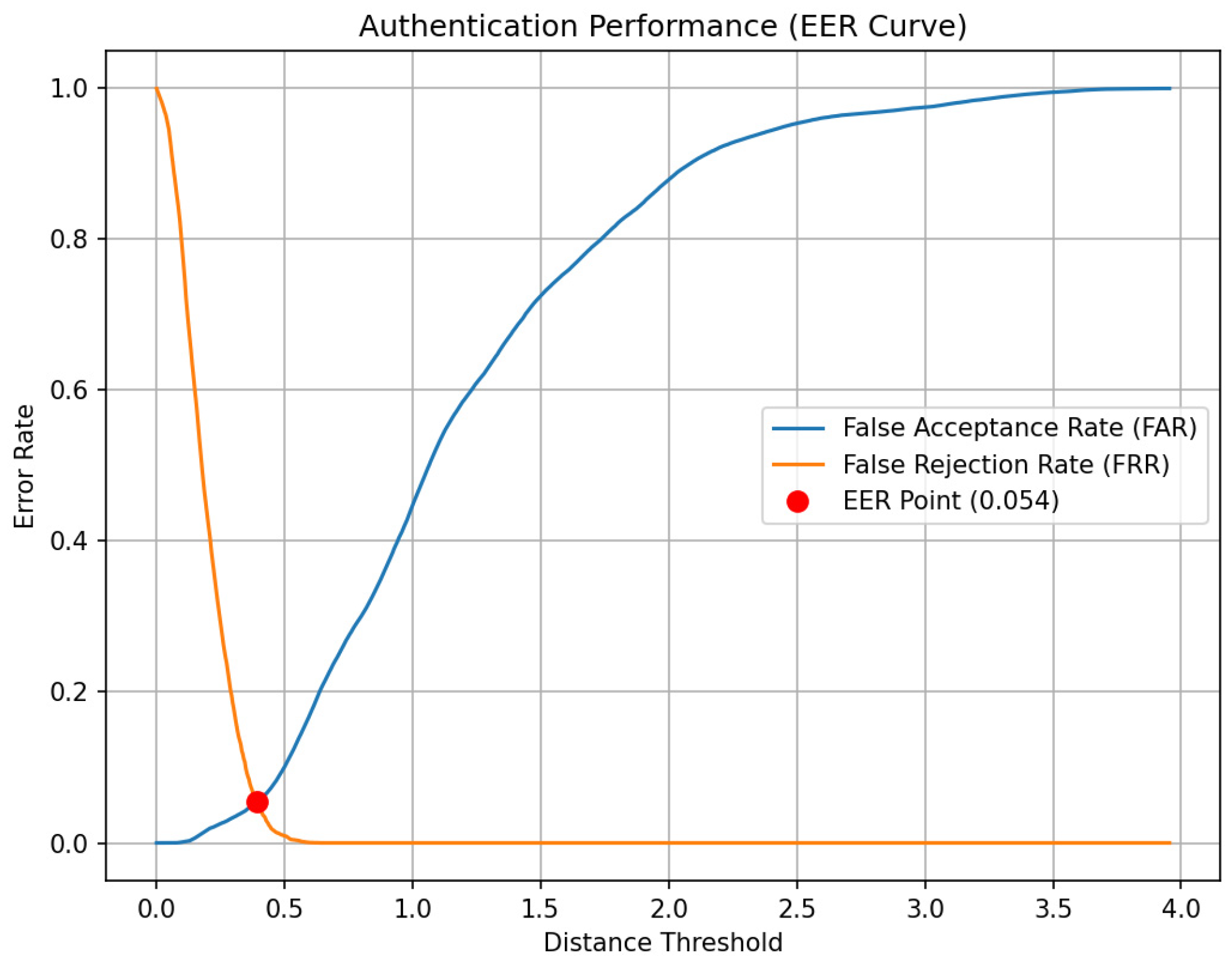
By continuously varying the decision threshold τ across the entire test set, we calculated the corresponding FAR and FRR. We then plotted the Equal Error Rate (EER) curve, as shown in Figure 9. The FAR and FRR curves have an intersection point. The error rate at this point is the EER. EER is a core metric for the system’s overall performance, representing the error rate when FAR equals FRR. Our experimental results show that the model’s EER is 5.4%. Even when faced with new devices completely unseen during training, our model maintained a low error rate. This demonstrates the feasibility and effectiveness of our method in open-set authentication scenarios.

7. Conclusions

This paper has proposed and validated a RFF identification framework based on channel estimation for C-V2X environments. During the fingerprint-extraction phase, the framework leverages the channel’s second-order statistics via the LMMSE estimator to mitigate noise and multipath effects. For the fingerprint-classification stage, this paper constructs a lightweight ShuffleNet V2 network, structurally optimized for fingerprint features, and incorporates an attention mechanism. Experimental results demonstrate that the framework achieves high classification accuracy in both stationary and mobile scenarios under low SNR conditions. Furthermore, tests conducted on various deep learning models have confirmed the generalizability and extensibility of the fingerprint-extraction method proposed herein. The robustness and lightweight characteristics of the proposed framework highlight its potential for on-site training and deployment in real-world IoV environments, offering an effective technical solution to the security-authentication challenges in IoV. It should be emphasized that the term lightweight in this paper refers specifically to our model itself, and not the entire RFF identification system.

Author Contributions

Conceptualization, L.S. and Y.X.; methodology, L.S. and Y.X.; software, Y.X. and Y.Y.; validation, L.S., Y.X. and Y.Y.; formal analysis, L.S. and Y.Y.; writing—original draft preparation, L.S. and Y.X.; writing—review and editing, L.S., Y.Y., Y.L. and N.F.; supervision, Y.L.; project administration, Y.L. All authors have read and agreed to the published version of the manuscript.

Funding

This research project was supported by the Researchers Supporting Project number (2024r001; 2024r020; 2024r087), Wuxi University, Wuxi, China.

Data Availability Statement

The original contributions presented in this study are included in the article. Further inquiries can be directed to the corresponding author.

Conflicts of Interest

The authors declare no conflict of interest.

References

  1. Kim, C.; Kwon, D.K.; Son, S.; Yu, S.; Park, Y. An Anonymous and Efficient Authentication Scheme with Conditional Privacy Preservation in Internet of Vehicles Networks. Mathematics 2024, 12, 3756. [Google Scholar] [CrossRef]
  2. Aziz, S.; Faiz, M.T.; Adeniyi, A.M.; Loo, K.H.; Hasan, K.N.; Xu, L.; Irshad, M. Anomaly detection in the internet of vehicular networks using explainable neural networks (xnn). Mathematics 2022, 10, 1267. [Google Scholar] [CrossRef]
  3. Anwar, W.; Franchi, N.; Fettweis, G. Physical layer evaluation of V2X communications technologies: 5G NR-V2X, LTE-V2X, IEEE 802. 11 bd, and IEEE 802.11 p. In Proceedings of the 2019 IEEE 90th Vehicular Technology Conference (VTC2019-Fall), Honolulu, HI, USA, 22–25 September 2019. [Google Scholar]
  4. Zhou, H.; Xu, W.; Chen, J.; Wang, W. Evolutionary V2X technologies toward the Internet of Vehicles: Challenges and opportunities. Proc. IEEE 2020, 108, 308–323. [Google Scholar] [CrossRef]
  5. Tan, Z.; Ding, B.; Zhao, J.; Guo, Y.; Lu, S. Breaking cellular IoT with forged data-plane signaling: Attacks and countermeasure. ACM Trans. Sens. Netw. 2022, 18, 59. [Google Scholar] [CrossRef]
  6. Ludant, N.; Robyns, P.; Noubir, G. From 5g sniffing to harvesting leakages of privacy-preserving messengers. In Proceedings of the 2023 IEEE Symposium on Security and Privacy (SP), San Francisco, CA, USA, 21–25 May 2023. [Google Scholar]
  7. Mosca, M. Cybersecurity in an era with quantum computers Will we be ready? IEEE Secur. Priv. 2018, 16, 38–41. [Google Scholar] [CrossRef]
  8. Zeng, K.; Govindan, K.; Mohapatra, P. Non-cryptographic authentication and identification in wireless networks [security and privacy in emerging wireless networks]. IEEE Wirel. Commun. 2010, 17, 56–62. [Google Scholar] [CrossRef]
  9. Yang, X.; Li, D. LED-RFF: LTE DMRS-based channel robust radio frequency fingerprint identification scheme. IEEE Trans. Inf. Forensics Secur. 2023, 19, 1855–1869. [Google Scholar] [CrossRef]
  10. Al-Shawabka, A.; Restuccia, F.; D’Oro, S.; Jian, T.; Rendon, B.C.; Soltani, N.; Dy, J.; Ioannidis, S.; Chowdhury, K.; Melodia, T. Exposing the fingerprint: Dissecting the impact of the wireless channel on radio fingerprinting. In Proceedings of the IEEE INFOCOM 2020—IEEE Conference on Computer Communications, Toronto, ON, Canada, 6–9 July 2020. [Google Scholar]
  11. Köse, M.; Taşcioğlu, S.; Telatar, Z. RF fingerprinting of IoT devices based on transient energy spectrum. IEEE Access 2019, 7, 18715–18726. [Google Scholar] [CrossRef]
  12. Vo-Huu, T.D.; Vo-Huu, T.D.; Noubir, G. Fingerprinting Wi-Fi devices using software defined radios. In Proceedings of the 9th ACM Conference on Security & Privacy in Wireless and Mobile Networks, Darmstadt, Germany, 18–20 July 2016. [Google Scholar]
  13. Hua, J.; Sun, H.; Shen, Z.; Qian, Z.; Zhong, S. Accurate and efficient wireless device fingerprinting using channel state information. In Proceedings of the IEEE INFOCOM 2018—IEEE Conference on Computer Communications, Honolulu, HI, USA, 16–19 April 2018. [Google Scholar]
  14. Xing, Y.; Hu, A.; Zhang, J.; Peng, L.; Wang, X. Design of a channel robust radio frequency fingerprint identification scheme. IEEE Internet Things J. 2022, 10, 6946–6959. [Google Scholar] [CrossRef]
  15. Tsipras, D.; Santurkar, S.; Engstrom, L.; Turner, A.; Madry, A. Robustness may be at odds with accuracy. arXiv 2018. [Google Scholar] [CrossRef]
  16. Xie, R.; Xu, W.; Yu, J.; Hu, A.; Ng, D.W.K.; Swindlehurst, A.L. Disentangled representation learning for RF fingerprint extraction under unknown channel statistics. IEEE Trans. Commun. 2023, 71, 3946–3962. [Google Scholar] [CrossRef]
  17. Al-Shawabka, A.; Pietraski, P.; Pattar, S.B.; Restuccia, F.; Tommaso, M. DeepLoRa: Fingerprinting LoRa devices at scale through deep learning and data augmentation. In Proceedings of the 22nd International Symposium on Theory, Algorithmic Foundations, and Protocol Design for Mobile Networks and Mobile Computing, Shanghai, China, 26–29 July 2021. [Google Scholar]
  18. Soltani, N.; Sankhe, K.; Dy, J.; Ioannidis, S.; Chowdhury, K. More is better: Data augmentation for channel-resilient RF fingerprinting. IEEE Commun. Mag. 2020, 58, 66–72. [Google Scholar] [CrossRef]
  19. Zhou, X.; Hu, A.; Li, G.; Peng, L.; Xing, Y.; Yu, J. A robust radio-frequency fingerprint extraction scheme for practical device recognition. IEEE Internet Things J. 2021, 8, 11276–11289. [Google Scholar] [CrossRef]
  20. Li, G.; Yu, J.; Xing, Y.; Hu, A. Location-invariant physical layer identification approach for WiFi devices. IEEE Access 2019, 7, 106974–106986. [Google Scholar] [CrossRef]
  21. Shen, G.; Zhang, J.; Marshall, A.; R. Cavallaro, J. Towards scalable and channel-robust radio frequency fingerprint identification for LoRa. IEEE Trans. Inf. Forensics Secur. 2022, 17, 774–787. [Google Scholar] [CrossRef]
  22. Dong, B.; Hu, A.; Yu, J.; Chen, H.; Shi, Z. A robust radio frequency fingerprint extraction method based on channel reciprocity. In Proceedings of the 2024 IEEE Wireless Communications and Networking Conference (WCNC), Dubai, United Arab Emirates, 21–24 April 2024. [Google Scholar]
  23. Yin, P.; Peng, L.; Zhang, J.; Liu, M.; Fu, H.; Hu, A. LTE device identification based on RF fingerprint with multi-channel convolutional neural network. In Proceedings of the 2021 IEEE Global Communications Conference (GLOBECOM), Madrid, Spain, 7–11 December 2021. [Google Scholar]
  24. Chen, T.; Shen, H.; Hu, A.; He, W.; Xu, J.; Hu, H. Radio frequency fingerprints extraction for LTE-V2X: A channel estimation based methodology. In Proceedings of the 2022 IEEE 96th Vehicular Technology Conference (VTC2022-Fall), London, UK, 26–29 September 2022. [Google Scholar]
  25. van de Beek, J.-J.; Edfors, O.; Sandell, M.; Wilson, S.K.; Borjesson, P.O. On channel estimation in OFDM systems. In Proceedings of the 1995 IEEE 45th Vehicular Technology Conference, Chicago, IL, USA, 25–28 July 1995. [Google Scholar]
  26. ETSI 3rd Generation Partnership Project. LTE; Evolved Universal Terrestrial Radio Access (E-UTRA); Physical Channels and Modulation (Release 14), 3GPP TS 36.211 version 14.2.0; Sophia Antipolis Cedex: Biarritz, France, 2016. [Google Scholar]
  27. Qi, X.; Hu, A.; Chen, T. Lightweight Radio Frequency Fingerprint Identification Scheme for V2X Based on Temporal Correlation. IEEE Trans. Inf. Forensics Secur. 2023, 19, 1056–1070. [Google Scholar] [CrossRef]
  28. Van de Beek, J.J.; Sandell, M. ML Estimation of Time and Frequency Offset in OFDM Systems. IEEE Trans. Signal Process. 1997, 45, 1800–1805. [Google Scholar] [CrossRef]
  29. Moose, P.H. A Technique for Orthogonal Frequency Division Multiplexing Frequency Offset Correction. IEEE Trans. Commun. 1994, 42, 2908–2914. [Google Scholar] [CrossRef]
  30. Ma, N.; Zhang, X.; Zheng, H.T.; Sun, J. Shufflenet v2: Practical guidelines for efficient cnn architecture design. In Proceedings of the European Conference on Computer Vision (ECCV), Munich, Germany, 8–14 September 2018. [Google Scholar]
  31. Zhang, X.; Zhou, X.; Lin, M.; Sun, J. Shufflenet: An extremely efficient convolutional neural network for mobile devices. In Proceedings of the IEEE Conference on Computer Vision and Pattern Recognition (CVPR), Salt Lake City, UT, USA, 18–23 June 2018. [Google Scholar]
  32. Woo, S.; Park, J.; Lee, J.Y.; Kweon, I.S. Cbam: Convolutional block attention module. In Proceedings of the European Conference on Computer Vision (ECCV), Munich, Germany, 8–14 September 2018; Springer: Cham, Switzerland, 2018. [Google Scholar]
Figure 1. Physical sidelink broadcast channel subframe signal structure.
Mathematics 13 03124 g001
Figure 2. Schematic diagram of RFF system.
Mathematics 13 03124 g002
Figure 3. (a) RFF processed without channel in a static scene. (b) RFF after channel processing in a static scene. (c) RFF processed without channel in a mobile scene. (d) RFF after channel processing in a mobile scene. (e) RFF processed without channel in a low SNR scene. (f) RFF after channel processing in a low SNR scene.
Mathematics 13 03124 g003
Figure 4. (a) Basic module. (b) Downsampling module.
Mathematics 13 03124 g004
Figure 5. Improve the overall architecture of the ShuffleNet V2.
Mathematics 13 03124 g005
Figure 6. Channel attention module.
Mathematics 13 03124 g006
Figure 7. Spatial attention module.
Mathematics 13 03124 g007
Figure 8. Accuracy at different signal-to-noise ratios.
Mathematics 13 03124 g008
Figure 9. Authentication performance (EER curve).
Mathematics 13 03124 g009
Table 1. Comparison of different channel-mitigation strategies in RFF identification.
(Method/Approach)AdvantagesLimitations
Transient Features [11,23]No data demodulation required.Significant performance degradation on persistent symbols.
CFO Features [12,13]Simple concept, channel estimation-free.Insufficient stability and inter-class separability.
Adversarial Training [15]/Disentanglement [16]Data-driven, automatic decoupling.Risk of “over-purifying” and losing RFF details.
Data Augmentation [17,18]Enhances model’s tolerance to variations.Increases model training overhead.
Noise Injection [19]Leverages physical principles, no preamble needed.Mismatches with the physical model of the actual channel.
Protocol-Specific Compensation [20,21]Performs well within its native system.Relies on specific frame structures.
Channel Reciprocity [22]Enhances model’s tolerance to variations.Requires stacking of multiple consecutive frames from the same transmitter.
LS Channel Estimation [24]Simple to implement, direct channel removal.Performance degrades under low SNR.
Table 2. Classification under different scenarios.
Training SetACC/F1 (%)
LOSNLOSMOV1MOV2MOV3
DC99.75/99.7398.82/98.5699.01/98.0598.09/98.5199.59/99.59
DC + LOS100/10099.96/99.9499.28/98.2399.41/99.51100/100
DC + NLOS95.64/95.06100/10099.89/99.9296.51/97.3599.67/99.67
DC + MOV1100/10099.32/99.33100/10097.72/98.699.87/99.87
DC + MOV299.96/99.9799.82/99.898.73/97.19100/10099.96/99.96
DC + MOV3100/10099.58/99.6799.6/99.5799.54/99.63100/100
LOS100/10099.28/98.7498.07/98.1995.68/95.7199.87/99.85
LOS + NLOS99.99/99.9999.99/99.9799.98/99.9898.27/98.12100/100
LOS + MOV1100/10098.99/99.16100/10098.89/98.9299.93/99.91
LOS + MOV2100/10099.28/99.499.92/99.92100/100100/100
LOS + MOV3100/10098.27/98.6899.24/99.4895.74/95.22100/100
Table 3. Comparison of different models.
ModelOverall Accuracy (%)Macro Precision (%)Macro F1 (%)
DenseNet95.1993.1593.92
MobileNet92.788.9388.12
EfficientNet96.6397.0296.24
MobileVit86.4785.0884.22
ConvNeXt96.729495.43
ShuffleNet V296.7495.0295.19
Ours99.0197.4498.05
Disclaimer/Publisher’s Note: The statements, opinions and data contained in all publications are solely those of the individual author(s) and contributor(s) and not of MDPI and/or the editor(s). MDPI and/or the editor(s) disclaim responsibility for any injury to people or property resulting from any ideas, methods, instructions or products referred to in the content.