Abstract
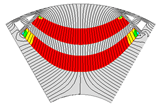
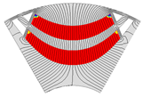
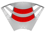
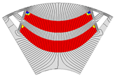
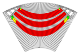
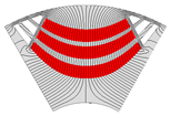
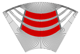
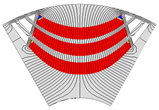
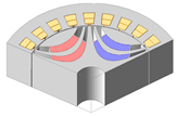
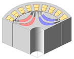
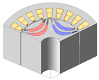
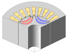
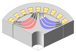
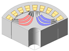
This paper presents the design of a permanent-magnet-assisted synchronous reluctance motor (PMa-SynRM) for compressor applications using Sm-series injection-molded magnets that eliminate heavy rare-earth elements. The high shape flexibility of the injection-molded magnets enables the formation of a curved multi-layer flux-barrier rotor geometry based on the Joukowski airfoil potential, optimizing magnetic flux flow under typical compressor operating conditions. Furthermore, electromagnetic performance, irreversible demagnetization behavior, and rotor stress sensitivity were analyzed with respect to key design variables to derive a model that satisfies the target performance requirements. The validity of the proposed design was confirmed through finite element method (FEM) comparisons with a conventional IPMSM using sintered NdFeB magnets, demonstrating the feasibility of HRE-free PMa-SynRM for high-performance compressor drives.
Keywords:
injection-molded magnets; irreversible demagnetization; Joukowski airfoil potential formula; permanent-magnet-assisted synchronous reluctance motor; rotor stress; finite element method MSC:
78M10; 78M50; 49Q10; 90C29; 74P10
1. Introduction
Interior permanent magnet synchronous motors (IPMSMs) offer high torque and power density, excellent efficiency, and a wide operational speed range, making them widely adopted in servo drives, home appliances, and new energy vehicles [1,2,3]. In line with these widespread applications, recent studies on PMSMs and IPMSMs have actively focused not only on various advanced control strategies but also on novel structural developments aimed at improving performance and cost competitiveness [4,5,6,7,8]. However, conventional IPMSMs rely on sintered Nd-based permanent magnets (PMs) that contain heavy rare-earth (HRE) elements, the supply of which is geographically concentrated. This dependence introduces supply chain risk, cost volatility, and sustainability concerns, alongside environmental impact issues [9]. Global market trends and policy initiatives targeting reduced reliance on critical materials have thus accelerated research on alternative magnet materials and innovative rotor topologies.
To mitigate HRE usage while maintaining motor performance, various rotor structures and magnet alternatives have been investigated [10,11,12,13]. Among them, permanent-magnet-assisted synchronous reluctance motors (PMa-SynRMs) using injection-molded HRE-free magnets have gained increasing attention [14]. Injection-molded magnets provide several advantages: they eliminate HRE dependence, improve air-gap mechanical stability, and reduce price fluctuations under global supply variations [15]. Consequently, the design of electric motors employing HRE-free injection-molded magnets can function as a practical alternative that simultaneously achieves material cost reduction and mitigation of the environmental burden associated with rare-earth mining and production, thereby securing both economic efficiency and sustainability. Moreover, their high shape flexibility enables the design of complex multi-layer flux-barrier rotors that enhance saliency ratios and reluctance torque, achieving power density and efficiency comparable to traditional Nd-based IPMSMs [16].
Despite these advantages, non-HRE magnets exhibit lower coercivity and remanence, making them more susceptible to irreversible demagnetization under fault conditions or elevated temperatures. In addition, the complex shapes required for multi-layer flux barriers introduce structural challenges, especially at high rotational speeds. While several studies have proposed fluid-shaped or analytically defined flux-barrier designs, comprehensive investigations considering demagnetization risk, mechanical integrity under centrifugal loading, and multi-objective trade-offs (torque density, torque ripple, efficiency, and safety margins) remain limited [17,18,19,20].
In this study, Sm-series injection-molded magnets are adopted to leverage their shape flexibility while addressing both demagnetization vulnerability and structural robustness. A curved multi-layer flux-barrier rotor is analytically formulated based on the Joukowski airfoil potential to optimize magnetic flux flow under typical compressor operating conditions. Irreversible demagnetization susceptibility is evaluated under fault-current and high-temperature scenarios, while rotor mechanical stress is analyzed using the finite element method (FEM) to ensure safety at high speeds. Sensitivity analysis and multi-objective optimization are employed to balance torque density, torque ripple, demagnetization margin, and rotor safety factor. The optimized two-layer and three-layer configurations are validated through FEM simulations under rated-speed and load conditions, and their feasibility is further confirmed by comparison with the experimental and simulation results of an existing IPMSM.
2. Design of HRE-Free PMa-SynRM with Conventional IPMSM
2.1. Configuration and Specifications of Conventional IPMSM
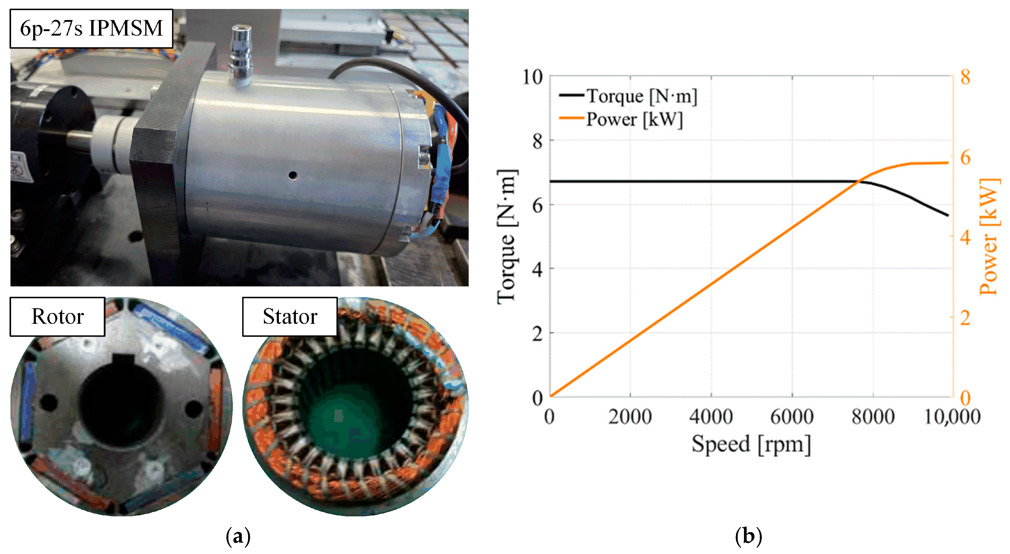
A conventional IPMSM is employed as the reference model to define performance benchmarks and design constraints. Specifically, a 6-pole, 27-slot IPMSM for compressor applications is adopted as the baseline model. The rotor–stator geometry of the reference machine is shown in Figure 1a, and its torque–speed and power–speed characteristics under typical operating conditions are illustrated in Figure 1b.
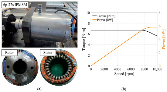
Figure 1.
Specifications of conventional IPMSM: (a) structure of 6p-27s IPMSM and (b) torque/power versus speed curves.
The reference IPMSM utilizes sintered NdFeB PMs embedded in the rotor core. The magnet grade and dimensions were selected to satisfy the required torque density and back-EMF characteristics for compressor drives.
In addition, since vibration and noise reduction are critical requirements for compressor motors, the pole–slot combination was selected with reference to validated design cases from previous studies to minimize cogging torque and torque ripple while enhancing efficiency [21,22]. The detailed specifications of the conventional model are summarized in Table 1.

Table 1.
Specifications of the conventional 6-pole, 27-slot IPMSM.
FEM analysis is employed to evaluate key electromagnetic and thermal parameters of the reference IPMSM, including flux linkage, phase inductance, operational losses, and thermal loading. These analyses establish baseline targets for efficiency and current density under rated operating conditions. The mechanical integrity of the rotor is further verified through FEM-based stress analysis at the maximum speed, with the safety factor (SF) determined from the material yield strength.
In addition, magnet demagnetization limits are assessed by combining the remanence and coercivity temperature coefficients of the sintered NdFeB PMs with the expected rotor temperature rise. This process yields an irreversible demagnetization margin that ensures reliable operation under thermal and fault scenarios. The derived electromagnetic, thermal, and mechanical characteristics serve as the benchmark and constraint framework for the subsequent PMa-SynRM design.
2.2. Modeling of Rotor Structure for HRE-Free PMa-SynRM
Since the torque density of a PMa-SynRM is strongly influenced by the rotor configuration, shape optimization considering the d–q axis inductance ratio (saliency ratio) is essential to achieve high torque density, improved efficiency, and reduced torque ripple. In this study, a fluid-type flux barrier is adopted because it aligns with the natural path of stator-originating flux lines, effectively blocking q-axis flux while minimally disturbing d-axis flux [23,24,25,26,27].
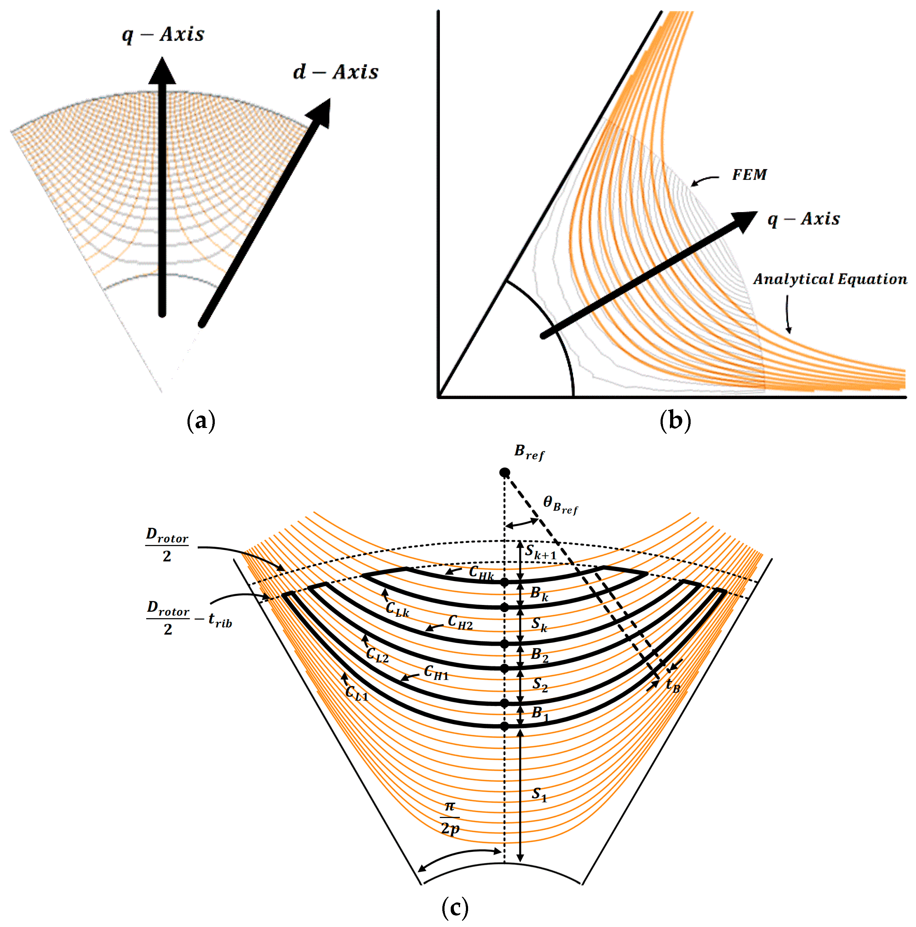
Figure 2a illustrates the d- and q-axis flux lines within the 6-pole rotor configuration. To generate a curved barrier that follows the d-axis flux trajectory, the Joukowski airfoil potential formulation is applied. The barrier-shape equations are expressed as
where r is the radial coordinate, θ is the mechanical angle measured from the d-axis, Dshaft is the shaft diameter, and p is the number of pole pairs [28,29,30,31]. Equation (1) defines the curved barrier contour along the d-axis flux, and Equation (2) specifies the equipotential constant Ψ.
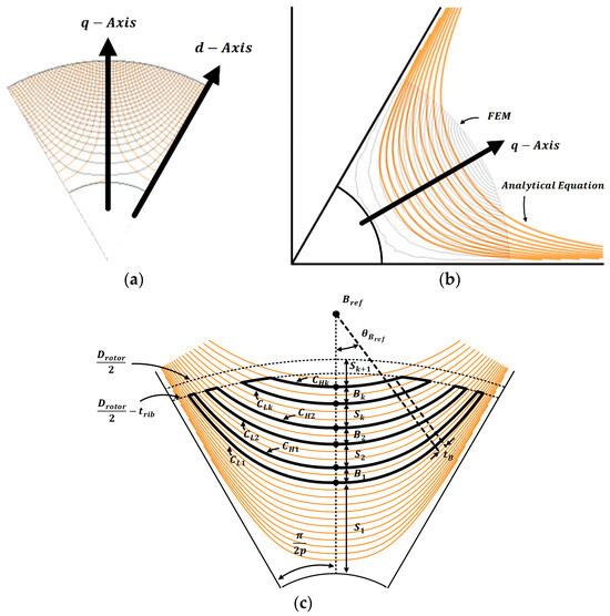
Figure 2.
Rotor flux analysis and parameter definition for PMa-SynRM: (a) d- and q-axis flux lines, (b) comparison of analytical and FEM flux lines, (c) design parameters based on the Joukowski airfoil formulation.
When the analytically generated barrier curve is superimposed on the FEM-calculated flux distribution, as shown in Figure 2b, the alignment with the d-axis flux trajectory is nearly exact. Based on these analytical curves, the rotor-shape design variables are defined, as illustrated in Figure 2c. The lower and upper barrier contours, CLk and CHk, are specified by selecting appropriate values of the equipotential constant Ψ. These two contours, combined with a reference circle of diameter Drotor, form a closed boundary whose interior is filled with injection-molded PMs. Here, Bk denotes the barrier thickness and Sk the stator tooth thickness between adjacent barriers. The bridging element between barriers is constructed by drawing a straight line from the reference point Bref, with its position, orientation θBref, and thickness tB adjusted to satisfy the mechanical and magnetic design requirements.
3. Robust Design Considering Electro-Mechanical Characteristics
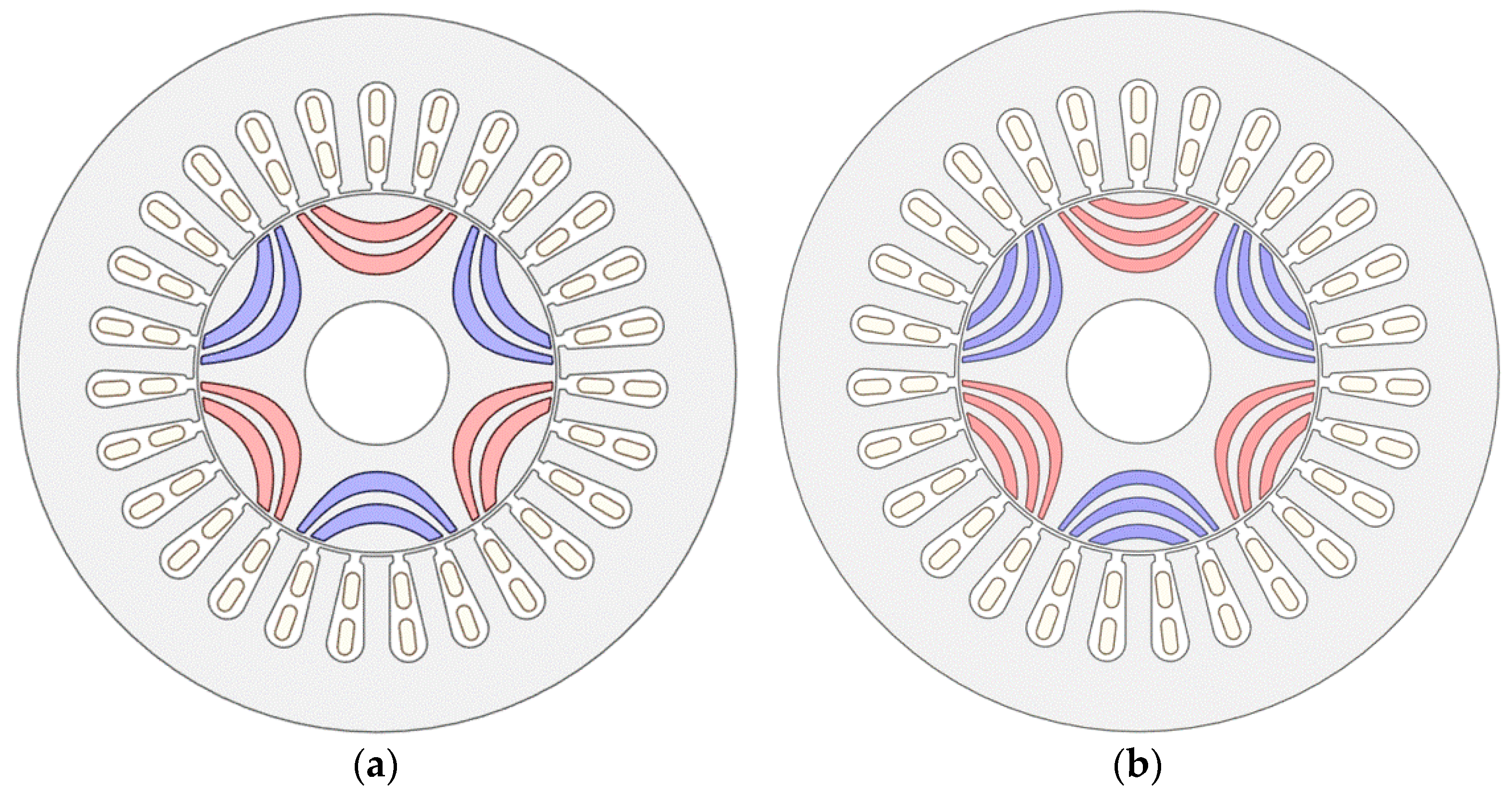
Figure 3a,b show the two-layer and three-layer PMa-SynRM geometries, respectively, designed via formula-based modeling. In order to evaluate the electromagnetic performance—accounting for irreversible demagnetization resistance due to permanent magnet coercivity degradation and for rotor stiffness induced by the more complex rotor structure—a sensitivity analysis of the objective functions with respect to the initial model design variables must be performed prior to optimization [32,33]. To this end, we first establish the requisite material properties and analysis conditions.
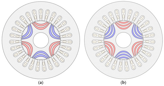
Figure 3.
Initial rotor geometries of PMa-SynRM: (a) 2-layer and (b) 3-layer models.
3.1. Criteria and Method of Irreversible Demagnetization Analysis
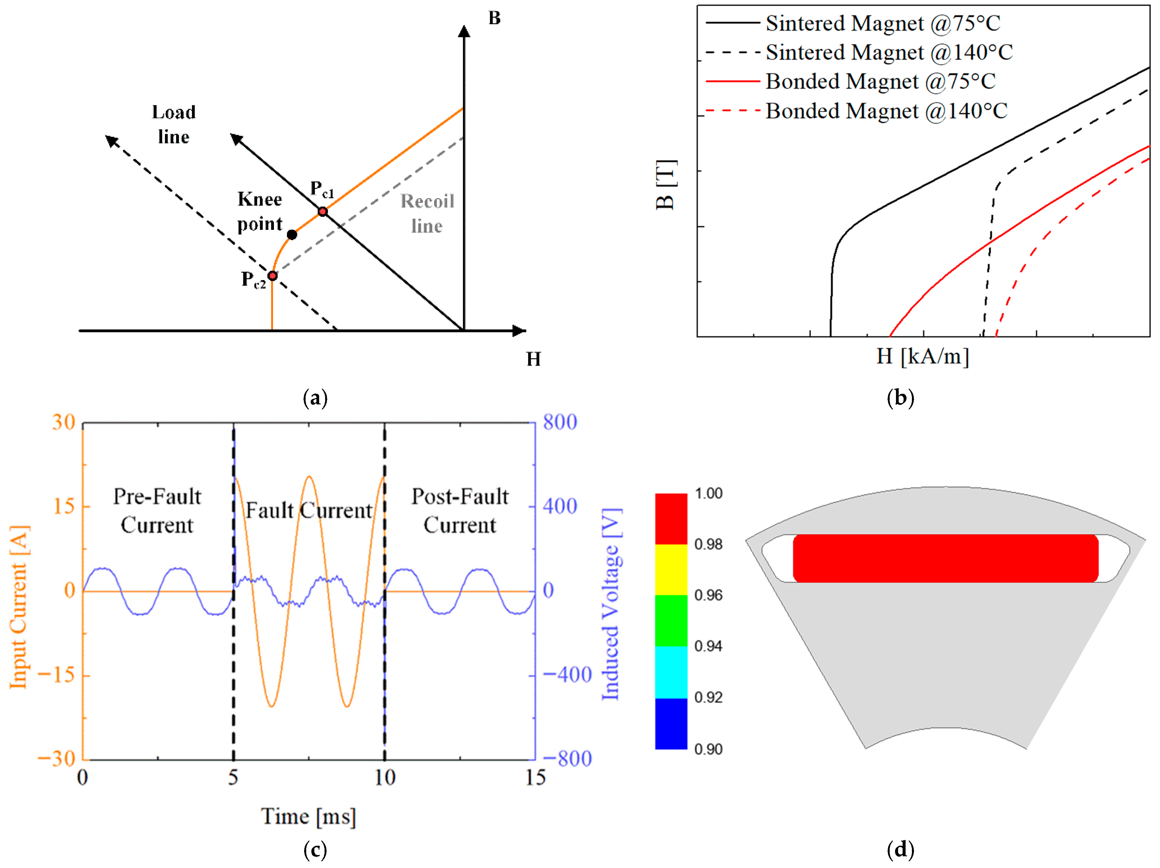
Irreversible demagnetization occurs when the operating load line falls below the knee point of the magnet’s B–H curve. In this case, a recoil line is formed, and the magnet does not return to its original residual flux level [34,35]. Figure 4a illustrates a typical B–H curve of a permanent magnet, showing that when the operating load line falls below the knee point, irreversible flux loss may occur [36]. Figure 4b shows the B-H curves of the sintered Nd magnet used in the conventional IPMSM and the injection-molded magnet used in the designed model. The injection-molded magnet has lower residual flux density and coercivity than the sintered Nd magnet, so if only the magnet is replaced in the same shape, the torque density decreases, and it becomes vulnerable to irreversible demagnetization. In addition, since the knee point is not distinct, demagnetization can easily occur even under a small load [37].
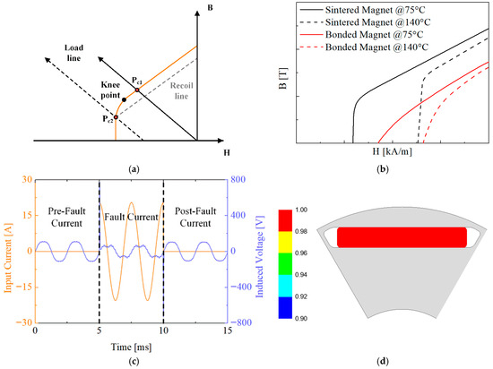
Figure 4.
Demagnetization characteristics: (a) typical B–H curve of PM, (b) comparison between sintered and injection-molded magnets, (c) back-EMF waveforms before and after fault current application, and (d) demagnetization coefficient of conventional IPMSM.
Figure 4c shows the demagnetization-analysis waveforms under overcurrent and nominal-current conditions. The occurrence of irreversible demagnetization is evaluated by calculating the rate of decrease in back-EMF between the initial cycle (cycles 1–2) and the post-overcurrent cycle (cycles 5–6) as defined by Equation (3) [38,39].
Furthermore, as shown in Figure 4d, by using ANSYS Maxwell 2023 version to measure the difference between the operating flux density after fault current (Brecoil) and the permanent magnet’s residual flux density (Bresidual) according to Equation (4), the demagnetized regions can be identified [40].
Table 2 summarizes the analytical criteria for judging irreversible demagnetization and presents the results for the conventional model. Under the specified test conditions, the conventional model exhibits a back-EMF reduction of approximately 0.16%, which—when accounting for manufacturing tolerances and FEM analysis uncertainties—indicates no irreversible demagnetization occurred [41,42].

Table 2.
Conditions and results of irreversible demagnetization analysis for the conventional IPMSM.
3.2. Rotor Mechanical Stress and Safety Factor
In the rotor design of high-speed, small-sized electric machines such as IPMSMs, PMa-SynRMs, etc., the internal structure composed of permanent magnets and ribs has a great influence on electromagnetic and mechanical performance [43,44,45]. For example, as the thickness of ribs decreases, the electromagnetic performance improves, but the structural stability can be significantly reduced [46]. In particular, in the case of a multi-layer curved barrier structure, the barrier size is increased compared to the conventional IPMSM, and the magnet quantity is increased, which increases the load acting on the rotor rib [47]. Therefore, it is essential to carry out design work with careful consideration of mechanical strength. The mechanical properties of the rotor core material are presented in Table 3. Based on these properties, FEM is performed to evaluate the internal rotor stresses. Using a conservative margin beyond the operational maximum speed of 8000 rpm, the structural stress analysis is conducted at 10,000 rpm, and the SF is set at a minimum of 1.5 [48].

Table 3.
Mechanical properties of rotor core and PM materials.
The SF is calculated as in (5), represents the yield strength, and represents the maximum stress value applied to the rotor. Figure 5 illustrates the contact conditions applied during stress analysis. A ‘bonded’ condition is assigned to the outer rotor contact surface, where the centrifugal force acts significantly during rotation, while a friction coefficient of 0.2 is applied to the remaining surfaces [49,50,51,52,53]. Additionally, because the analysis utilizes a segmented model, frictionless conditions are applied to the segmented surfaces.

Figure 5.
Boundary conditions for rotor mechanical stress analysis.
4. Multi-Objective Optimization
Based on the aforementioned discussions, following a sensitivity analysis of various design variables under irreversible demagnetization and mechanical stress conditions, an optimal design was developed to achieve the target electromagnetic performance and safety factor (SF) while ensuring robustness against irreversible demagnetization.
4.1. Optimization Framework for Multiple Variables and Objective
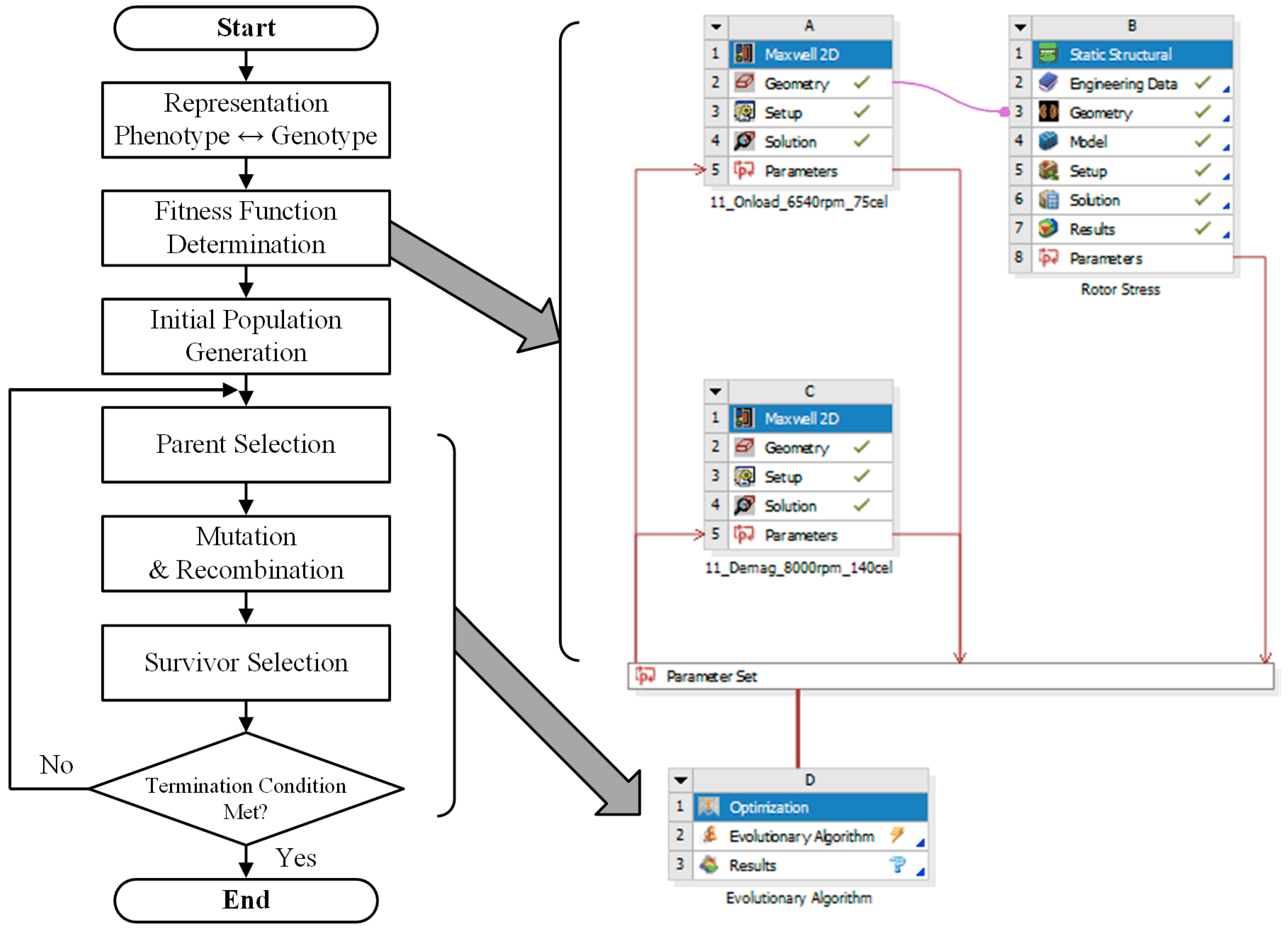
Evolutionary algorithms (EAs) are stochastic search techniques that mimic natural evolutionary processes such as selection, recombination, and mutation [54]. An initial population of candidate solutions is randomly generated in the solution space, and an abstract fitness function is used to evaluate the quality of each individual. Individuals with higher fitness are then selected and subjected to recombination or mutation operators to produce offspring, and this process is iterated—evaluating and breeding successive generations—until sufficiently high-quality solutions emerge [55]. In this paper, we leverage the particular advantage of EAs in handling global optimization problems with complex constraints and multiple objectives simultaneously [56]. Figure 6 illustrates the multi-objective optimization framework that integrates the EA flowchart with Ansys Workbench. In this framework, the fitness function is defined to incorporate electromagnetic performance, irreversible demagnetization limits, and rotor stiffness characteristics. Prior to optimization, a sensitivity analysis is conducted on each design variable, and allowable ranges and objective functions are then defined for the selected variables.
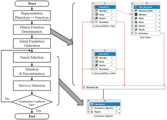
Figure 6.
EA optimization flow chart and electromagnetic–demagnetization–stress coupled optimization process using Ansys Workbench.
4.2. Sensitive Analysis with Design Variables
4.2.1. Barrier Position and Thickness
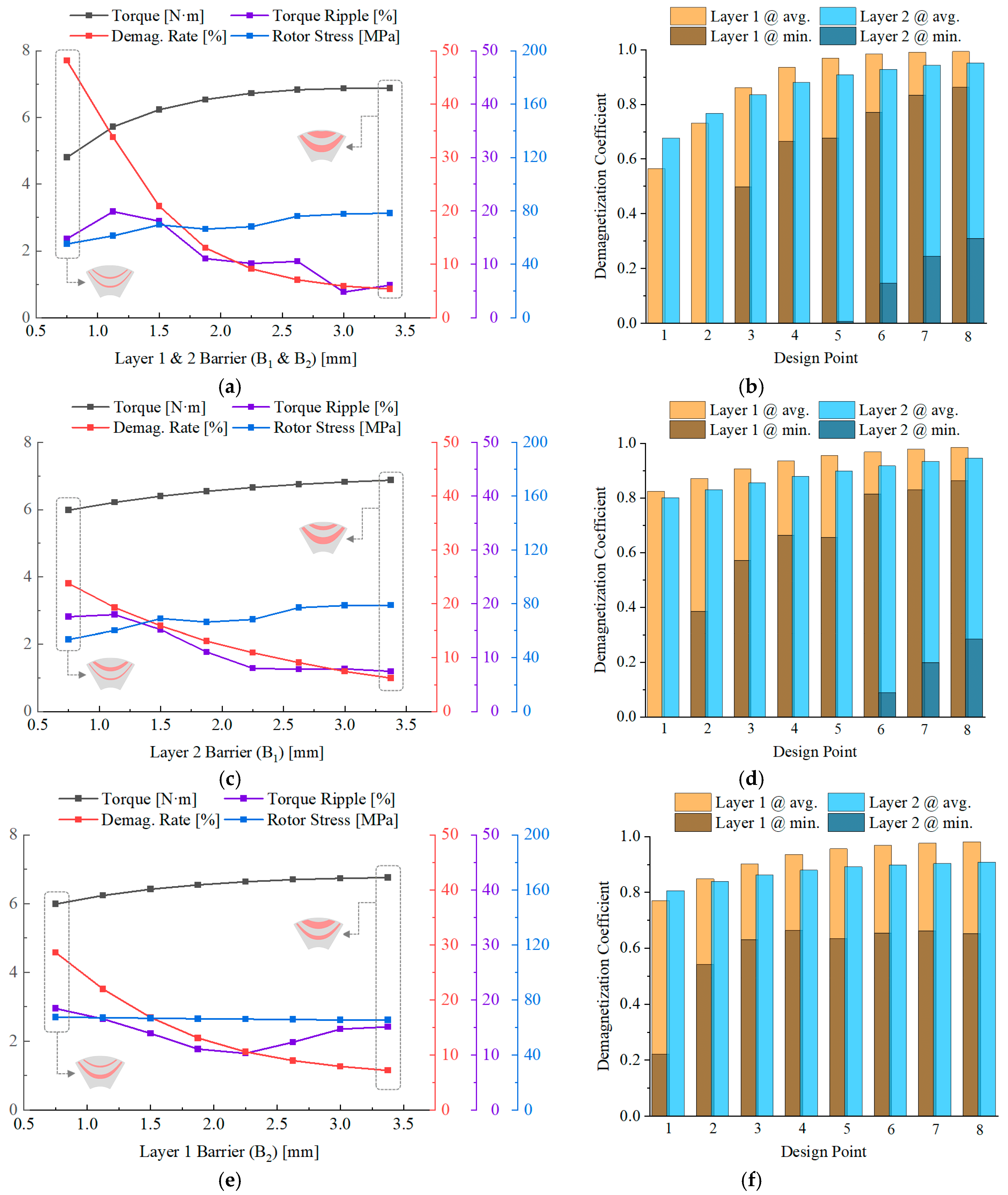
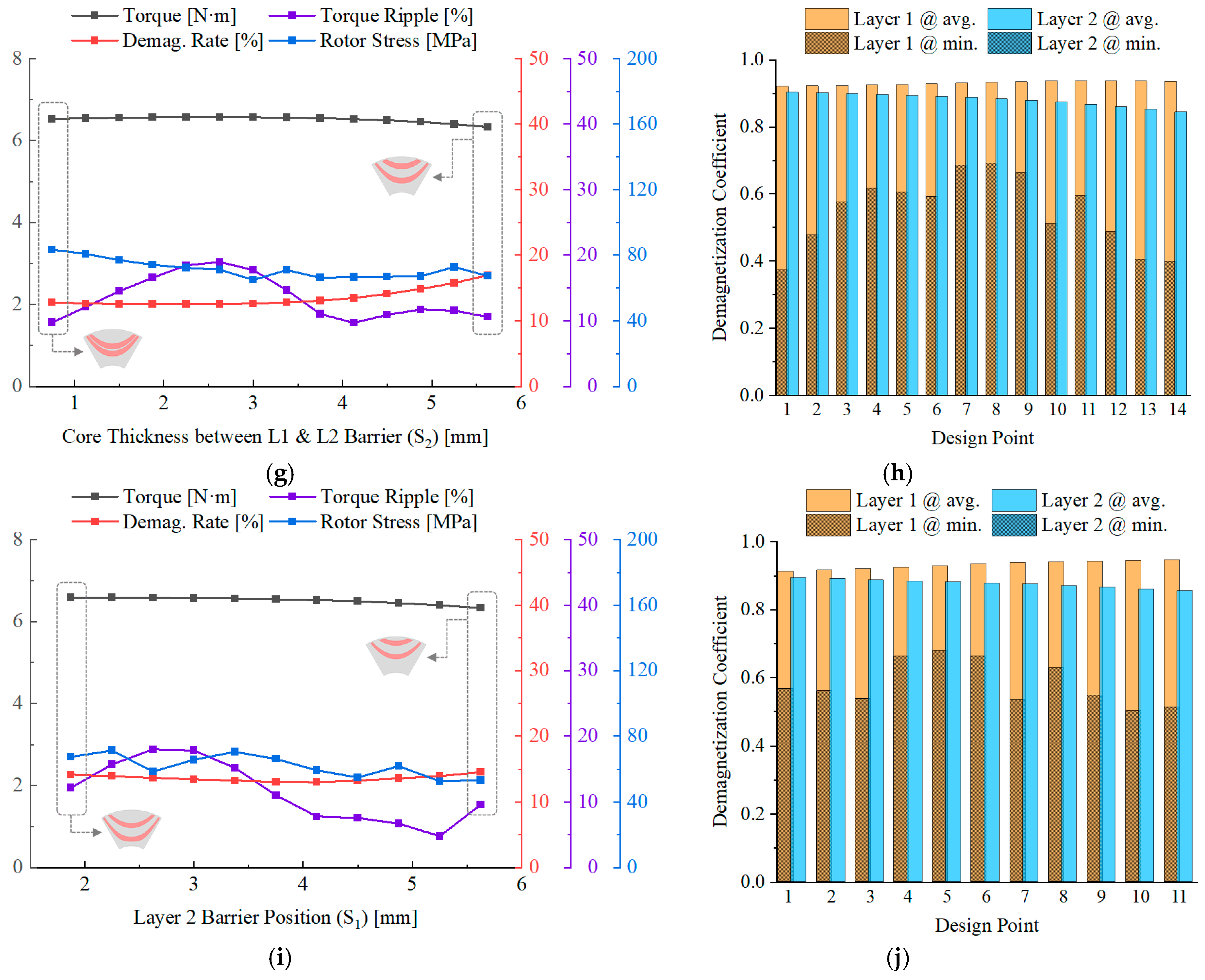
First, the sensitivity of electro-mechanical performance to barrier position and thickness is evaluated. Figure 7 shows the results of the sensitivity analysis according to each design variable. The changes in torque, torque ripple, irreversible demagnetization, and rotor stress were analyzed according to the barrier thickness and location in each layer. In particular, in the case of irreversible demagnetization, the changes in the average and minimum values of the demagnetization coefficient in each layer were analyzed as shown in Figure 7b,d,f,h,j.
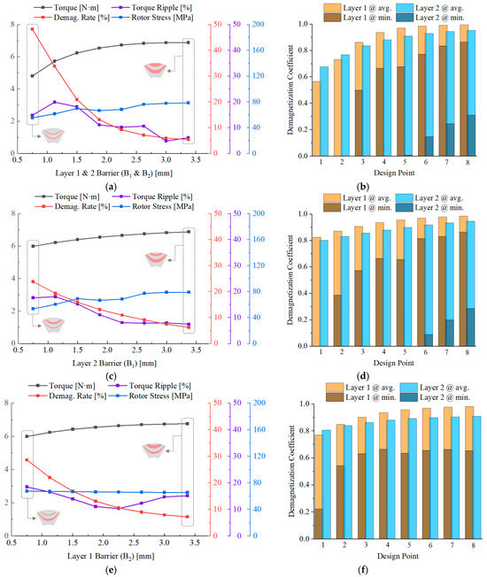
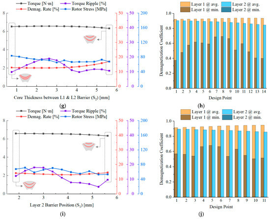
Figure 7.
Sensitivity analysis of 2-layer PMa-SynRM barrier thickness and position variation: (a,c,e,g,i) key performances as a function of design variables, (b,d,f,h,j) average and minimum demagnetization coefficients of each layer of permanent magnets as a function of design variables.
The results of the sensitivity analysis for variations in barrier thickness and position are as follows:
- The barrier thickness of each layer should not differ greatly;
- Magnets in the lower layer should be thicker;
- Barrier spacing is highly sensitive to torque ripple;
- Barrier position does not significantly affect performance, except for torque ripple;
- All irreversible demagnetization occurs at the ends of the barriers.
Figure 7a–f show the analysis results according to the barrier thickness, indicating that irreversible demagnetization of the permanent magnet becomes more severe in the lower layers. In addition, when the lower-layer barrier is thinner than the upper-layer barrier, torque ripple tends to increase. This is because a thinner lower-layer barrier cannot effectively block the armature reaction, leading to increased q-axis flux leakage. As a result, higher-order harmonics in the air-gap flux density waveform increase, thereby intensifying torque ripple. Therefore, the lower-layer barrier should be designed to be thicker. Figure 7g,h present the analysis results according to the spacing between barriers. The S2 spacing is highly sensitive to torque ripple, while other performance indicators show little change. However, when the spacing becomes excessively wide, flux paths in the interlayer core become more complex, and flux tends to concentrate at the barrier ends, which can aggravate irreversible demagnetization.
Finally, as shown in Figure 7i,j, changes in the barrier position (S1) did not significantly affect irreversible demagnetization. This is because demagnetization mainly occurs at the barrier ends, where the thickness is small and the energy contribution is limited, and changes in S1 do not substantially alter the influence of the armature reaction in these regions. Based on the above sensitivity analysis results, the optimal points for the two-layer and three-layer models were derived.
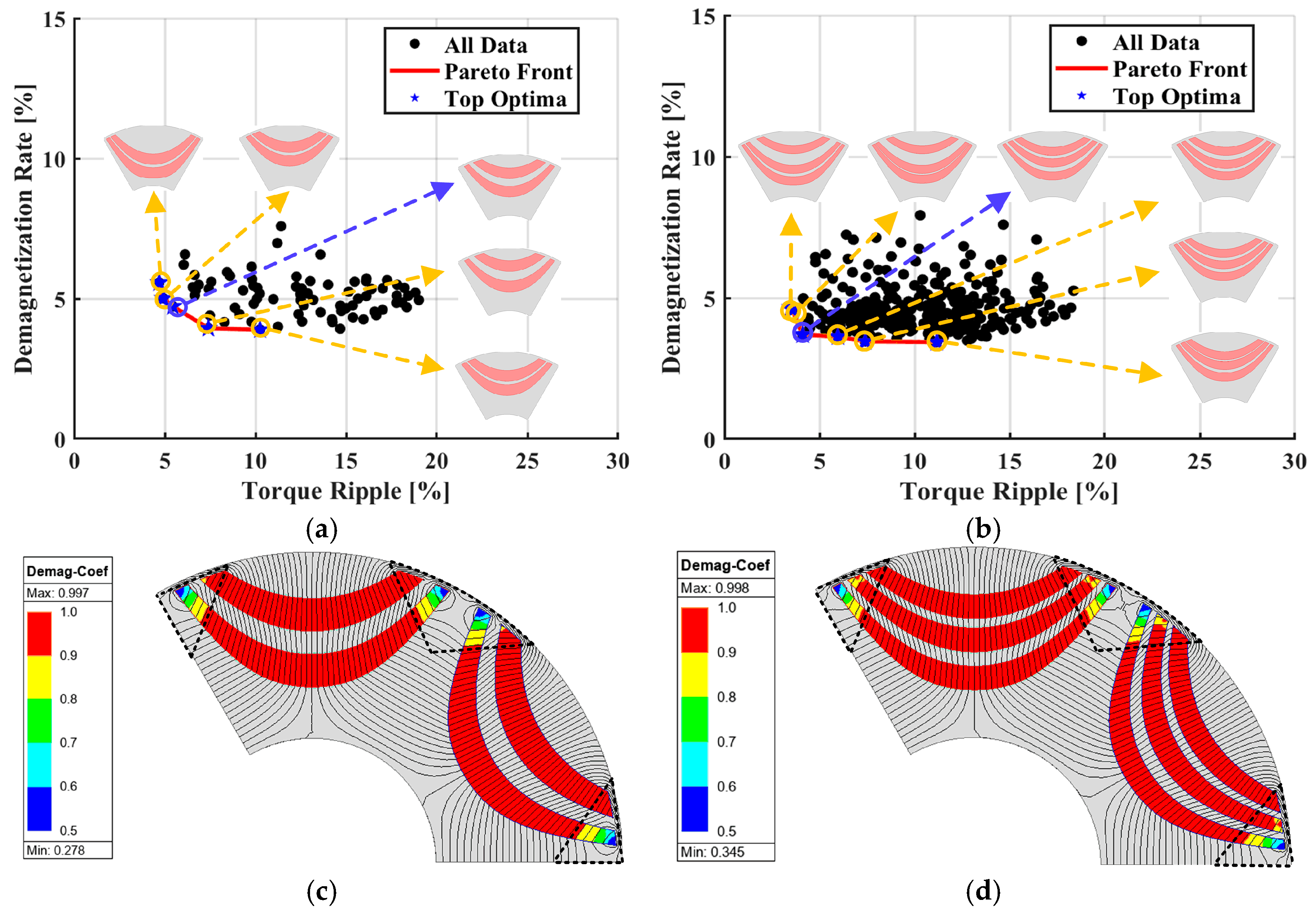
Figure 8a,b show the analysis results of the two-layer and three-layer PMa-SynRMs with torque ripple and irreversible demagnetization as objective functions, and Table 4 summarizes the electromagnetic analysis results at their respective optimal points. Although the overall performance differences between the two models are minor, the torque ripple of the three-layer model is about 50% of that of the two-layer model, making it more advantageous in terms of vibration and noise. This is related to the structural characteristic of barriers forming saliency. The two-layer model requires relatively thicker bridges than the three-layer model to secure sufficient saliency, which increases the effective air-gap length and thereby amplifies torque ripple. In contrast, the three-layer model can achieve the required performance with thinner bridges, which is more favorable for torque ripple suppression.
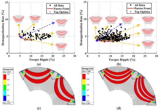
Figure 8.
Optimization results and demagnetization maps: (a,b) Pareto front of torque ripple vs. irreversible demagnetization for 2-layer and 3-layer PMa-SynRMs, (c,d) demagnetization regions at the selected optimal points.

Table 4.
Electromagnetic analysis results of 2-layer and 3-layer PMa-SynRMs at the optimal point.
In addition, even when adjusting the position and thickness of the barriers, irreversible demagnetization cannot be completely eliminated. To mitigate this issue, the barrier ends indicated by the black dotted lines in Figure 8c,d should be removed, and bridges should be added in consideration of the injection molding process to reinforce regions vulnerable to irreversible demagnetization.
4.2.2. Bridge Position and Angle
The bridge is designed using the variables of Figure 2 presented above. represents the origin of the coordinate system that will be the reference when designing the bridge, and represents the angle of the bridge created based on . The tip of the magnet to be removed strongly affects electromagnetic performance. As more material is removed, irreversible demagnetization improves, but electromagnetic performance deteriorates. This trade-off must be considered in the design.
Therefore, it is necessary to find a position where the demagnetization can be completely removed while minimizing performance degradation. Currently, both the two-layer and three-layer models have an SF of about 5, which is ample room. Therefore, the bridge thickness is fixed to 0.5 mm, the minimum thickness considering manufacturability, and the analysis is conducted.
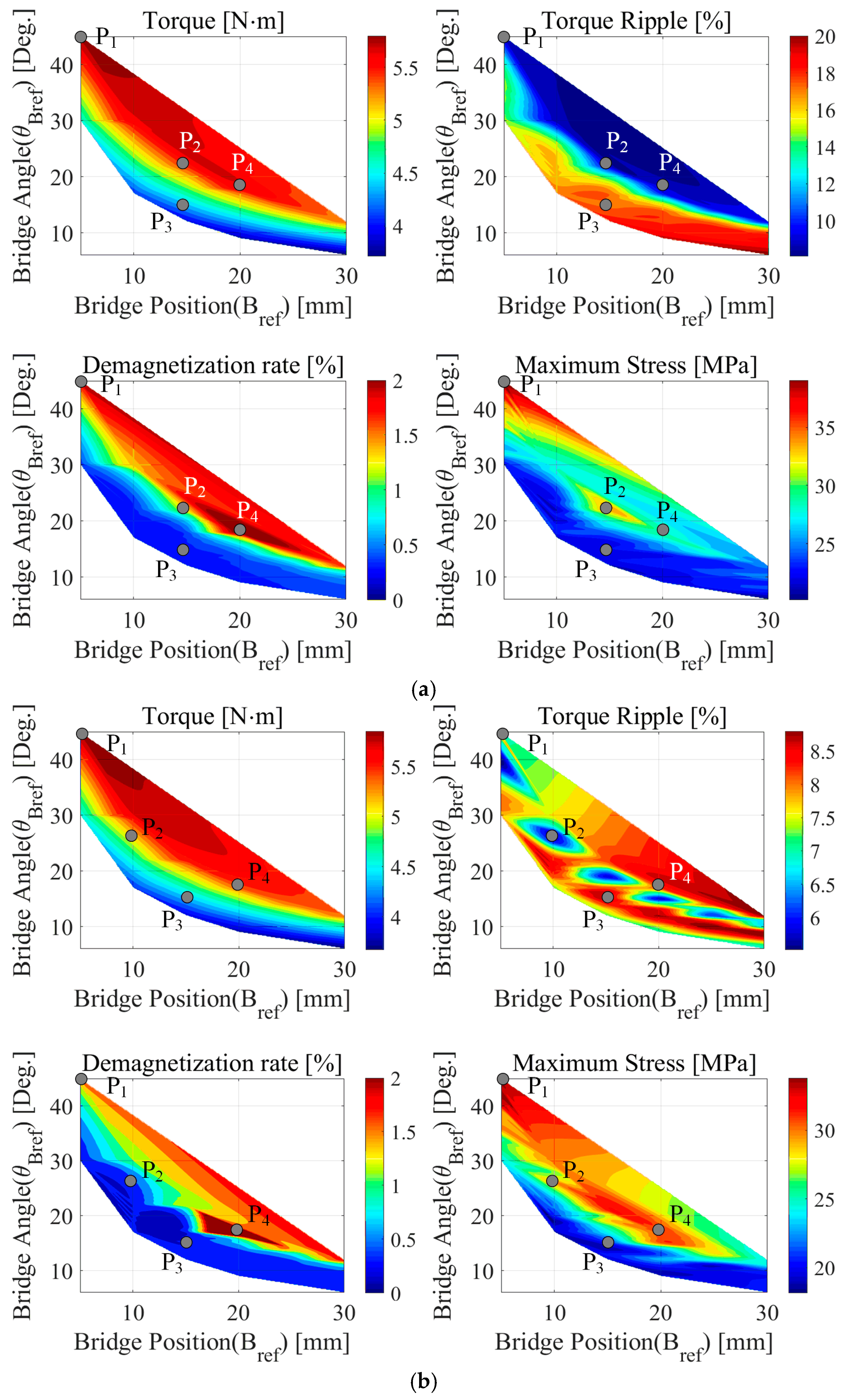
Figure 9 shows the electromagnetic performance, irreversible demagnetization, and maximum stress on the rotor of two-layer and three-layer PMa-SynRMs according to the changes in and . When is small and is large, fewer magnets are removed. In this case, torque is high and torque ripple is low, but the improvement in irreversible demagnetization is limited. When is large and is small, more magnets are removed. This increases the improvement in irreversible demagnetization, but torque decreases and torque ripple becomes very large. This seems to be the result of the decrease in the effective pole arc ratio and the decrease in the magnetic torque due to the decrease in the amount of magnets. As a representative, four design points were selected from each model of the second and third layers, and the performance comparison was performed, as shown in Table 5. As the amount of magnets removed increases from P1 to P3, the irreversible demagnetization almost disappears, but it has a negative effect on the torque and torque ripple. In addition, as the bridge is set parallel to the q-axis, such as in P4, the irreversible demagnetization in the front corner of the first-layer magnet becomes more severe. Therefore, it is impossible to design a model that satisfies the existing performance while eliminating the irreversible demagnetization with only the variables currently being touched.
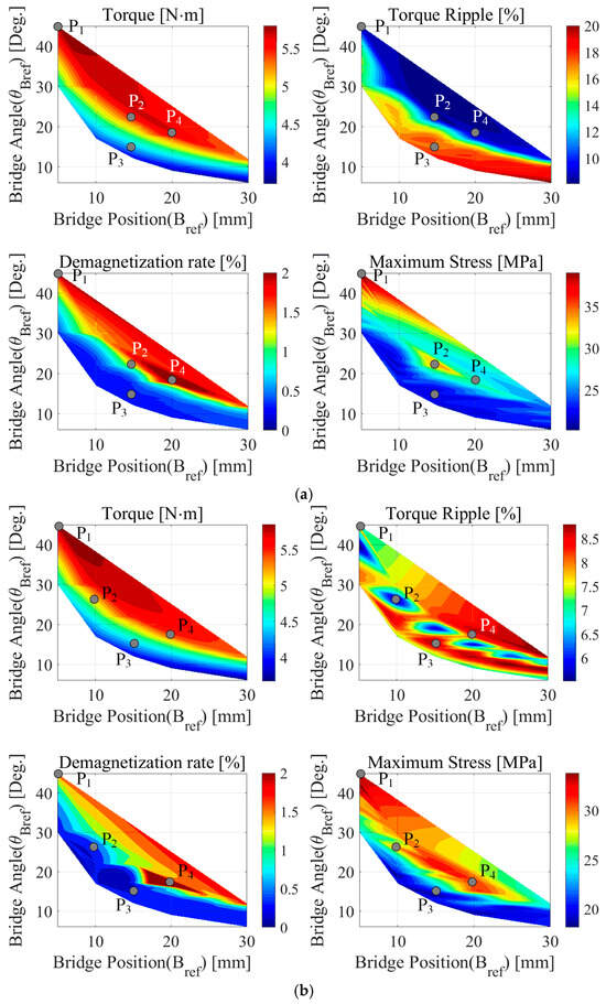
Figure 9.
Effect of bridge reference position Bref and angle θBref on the performance of (a) 2-layer and (b) 3-layer PMa-SynRMs.

Table 5.
Performance comparison of representative design points for 2-layer and 3-layer PMa-SynRMs.
4.2.3. Split Ratio and Aspect Ratio
The internal space of the rotor must be secured by changing the split ratio (SR) to increase the number of magnets, and the outer diameter ratio must be increased by changing the aspect ratio (AR) to secure electromagnetic performance. During analysis, the slot depth and tooth thickness were changed so that the number of turns and the fill factor could be maintained the same.
SR is the ratio of the rotor outer diameter to the stator outer diameter, where in Equation (3) represents the stator outer diameter and represents the rotor outer diameter [57]. Aspect ratio is the ratio of the axial length to the machine’s outer diameter, where in Equation (4) represents the axial length [58,59]. Since both design variables directly affect the torque, performance analysis according to SR and AR changes is conducted first before the optimal model is selected.
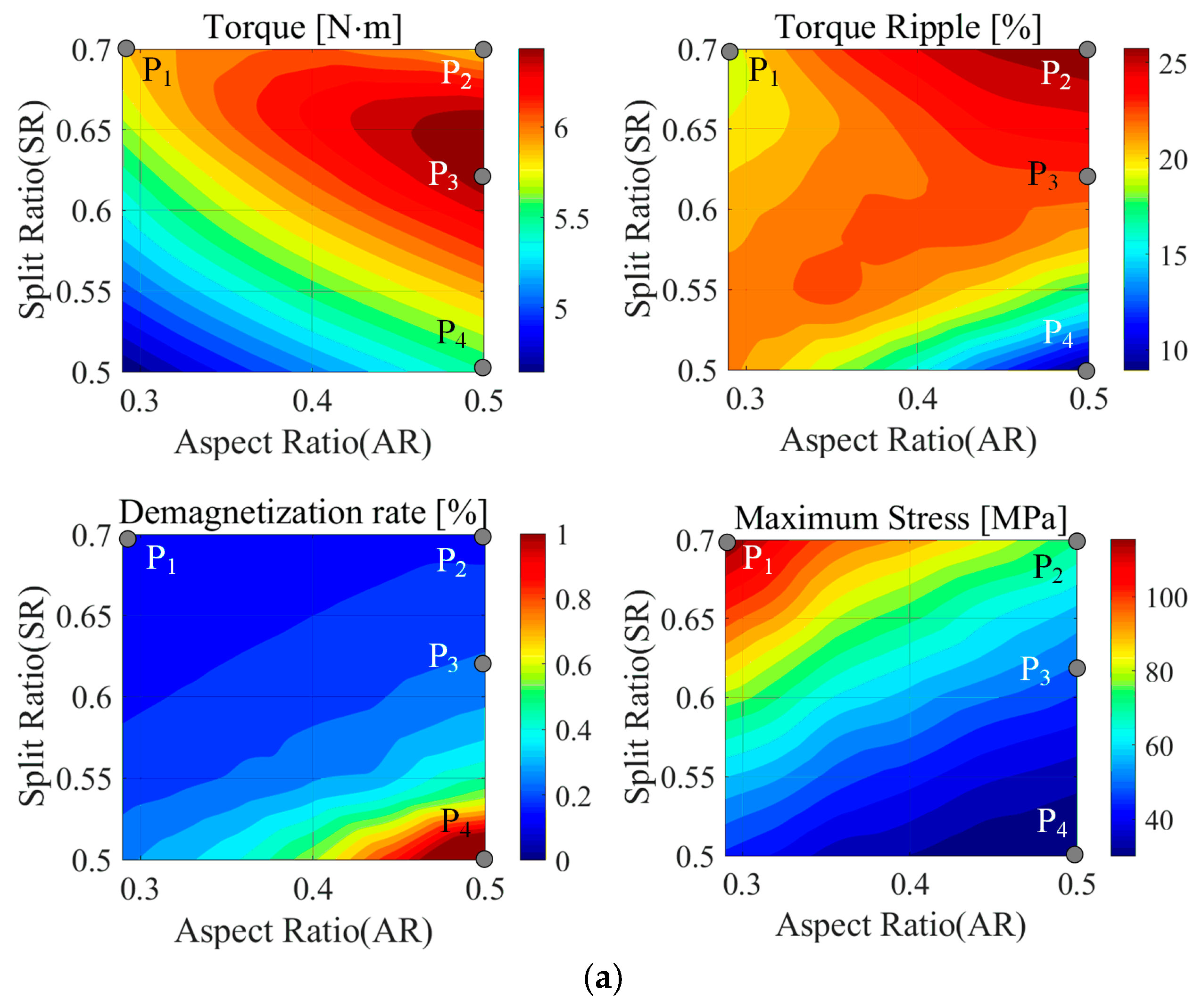
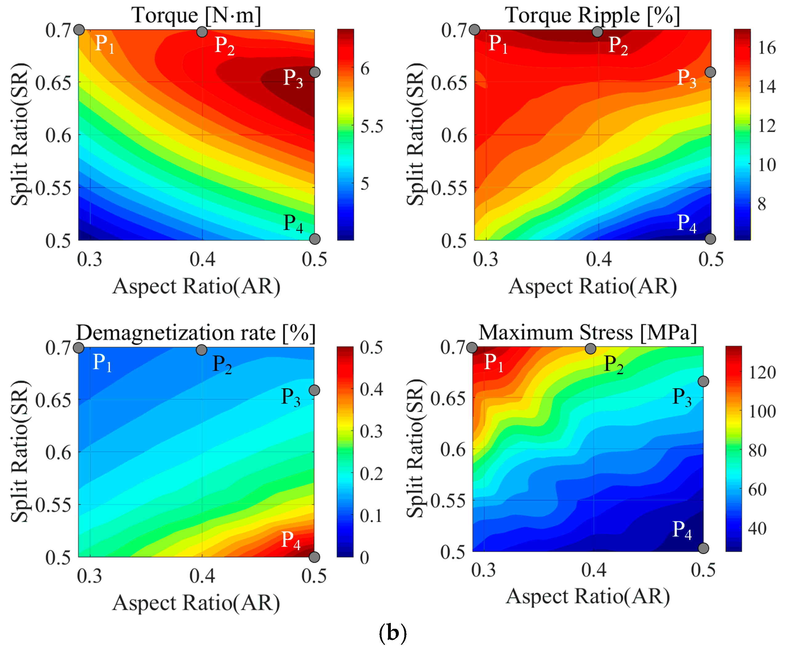
Figure 10 shows the results of performance analysis according to SR and AR changes. The performance change trends according to SR and AR changes are similar in the two-layer and three-layer models. In addition, as AR decreases and SR increases, the irreversible demagnetization rate decreases, but the maximum stress generated in the rotor increases due to the increase in . In addition, torque tends to increase as AR increases and SR increases.
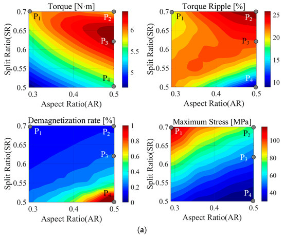
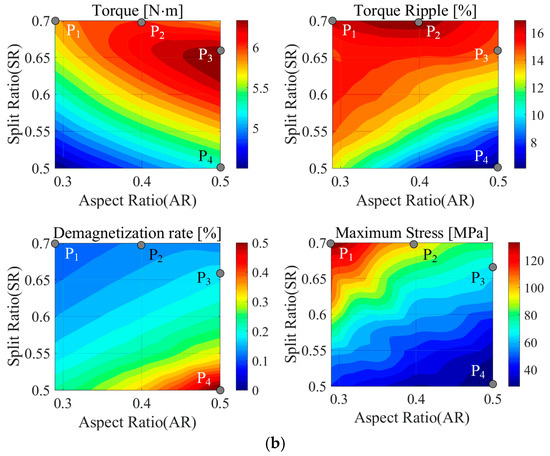
Figure 10.
Performance variation according to SR and AR for (a) 2-layer and (b) 3-layer PMa-SynRMs.
Representatively, four design points were selected from each of the two-layer and three-layer models to compare performance values, and the results are shown in Table 6. Irreversible demagnetization tends to improve as AR decreases and SR increases, and there is a trade-off relationship with maximum stress. The P1 model is the most robust point for irreversible demagnetization, and although there is almost no demagnetization, it can be seen that the maximum stress value is large. In the case of torque ripple, it changes more sensitively to changes in SR than in AR, and the P2 and P4 models represent the models with the largest and smallest torque ripple. The P4 model has the smallest torque ripple because the end magnets are relatively less removed, but the irreversible demagnetization is the most severe. The model with the largest torque is the P3 model, and the torque tends to increase and then decrease again as SR increases at the same AR. This seems to be due to a decrease in performance due to saturation as the stator area decreases while the same number of turns and fill factor are maintained.

Table 6.
Performance comparison at selected SR and AR design points for PMa-SynRMs.
5. Results and Discussion
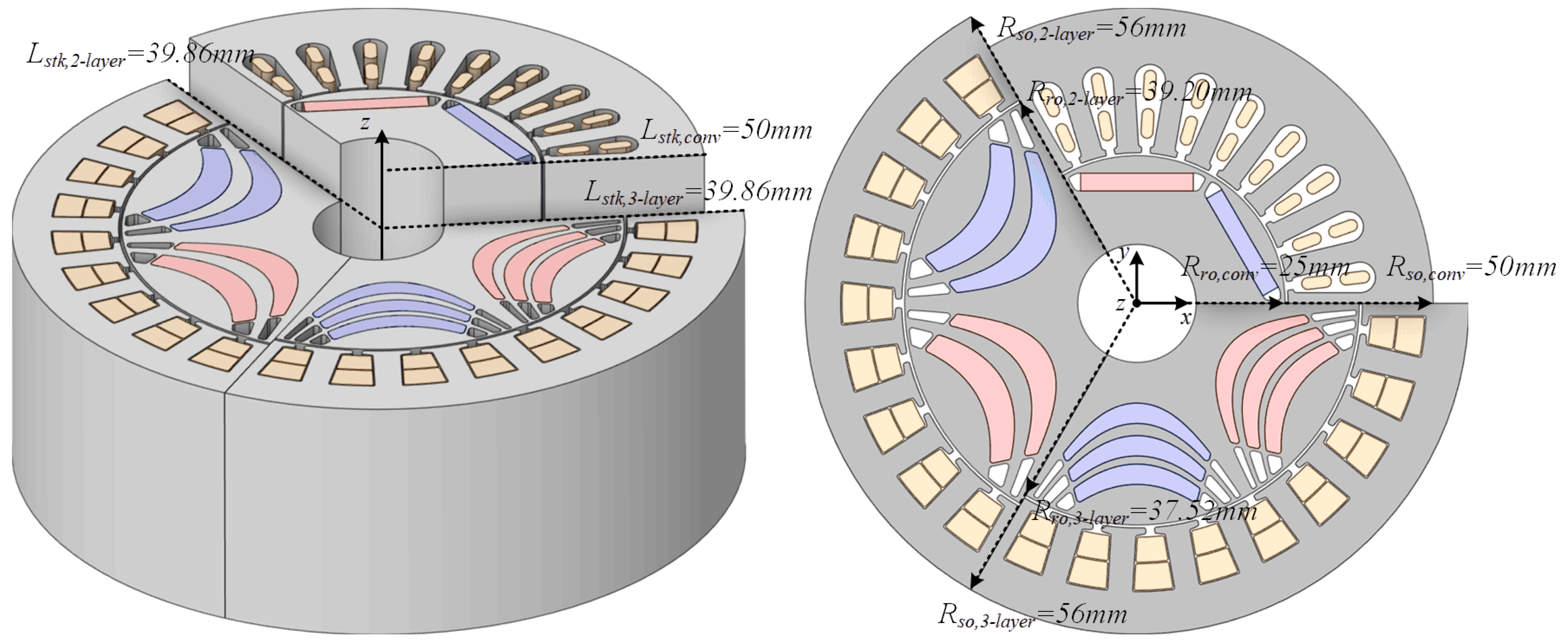
Based on the results of the performance sensitivity analysis according to the design variables analyzed in Section 4, the optimal models of the two-layer and three-layer PMa-SynRM are derived and compared with the reference model. Figure 11 is a comparison of the geometry of the conventional bar-type IPMSM with the final two-layer and three-layer PMa-SynRMs.
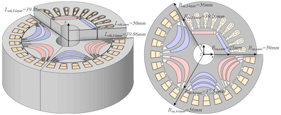
Figure 11.
Comparison of final geometries of the conventional IPMSM and the optimized 2-layer and 3-layer PMa-SynRMs.
5.1. Comparison of Electromagnetic Performances with Conventional IPMSM
First, the electromagnetic performance was compared with the conventional model at the rated speed point. Table 7 shows the electromagnetic performance comparison at the rated speed of 6540 rpm. In both designs, the torque ripple increased significantly because the outer part of the permanent magnet was removed to prevent irreversible demagnetization. In addition, the copper loss increased compared to the conventional model, which is due to the increase in the length of the end-turn part of the winding due to the increase in the outer diameter. The iron loss increased slightly due to the increase in stator saturation due to the increase in SR. The permanent magnet eddy current loss is much smaller than that of the sintered magnet due to the low electrical conductivity of the injection-molded magnet. However, its proportion in the electromagnetic loss is very low, so it does not have a significant effect on the efficiency. Ultimately, the electromagnetic efficiency of both models decreased slightly compared to the conventional model.

Table 7.
Comparison of electromagnetic performance between the conventional and the proposed designs at rated speed.
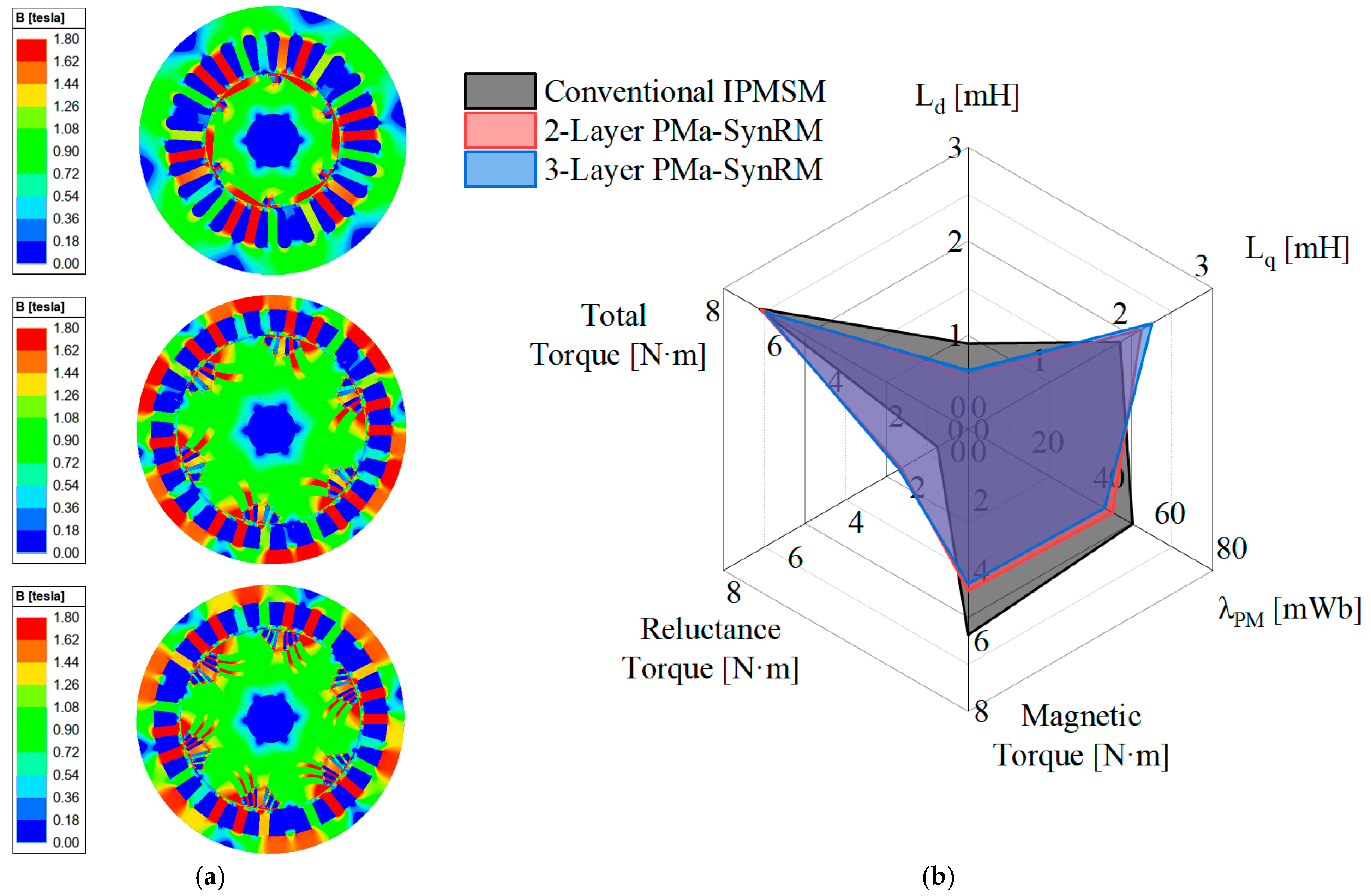
Figure 12a shows the magnetic flux density distribution of each model. Both designs have high magnetic flux density saturation due to the decrease in stator yoke width caused by the increase in SR. Figure 12b is a graph comparing the main electromagnetic parameter values of the conventional model and the design models. Due to the change in permanent magnet material, was lowered compared to the existing model, which reduced the magnetic torque, and the torque density was compensated by increasing the reluctance torque by increasing .
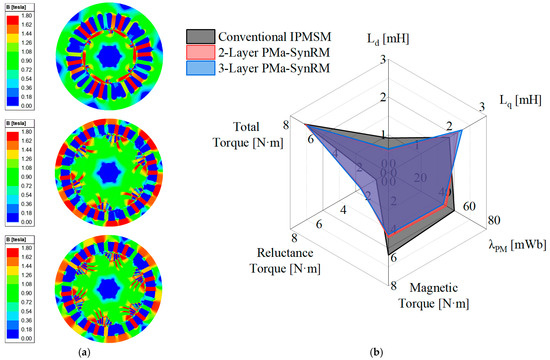
Figure 12.
Electromagnetic performance comparison: (a) magnetic flux density distribution of each model, (b) key electromagnetic parameters of the conventional and proposed models.
Figure 13 is a graph showing the efficiency map and key operating points of each model, and Table 8 is a table comparing the efficiency at key operating points. The efficiency decreased slightly compared to the conventional model due to the increase in copper loss and iron loss, and there is almost no difference in efficiency between the designed two-layer model and the three-layer model.

Figure 13.
Efficiency maps and key operating points: (a) conventional IPMSM, (b) 2-layer PMa-SynRM, (c) 3-layer PMa-SynRM.

Table 8.
Efficiency at key operating speeds for the conventional and proposed models.
5.2. Analysis Results of Irreversible Demagnetization and Mechanical Stress
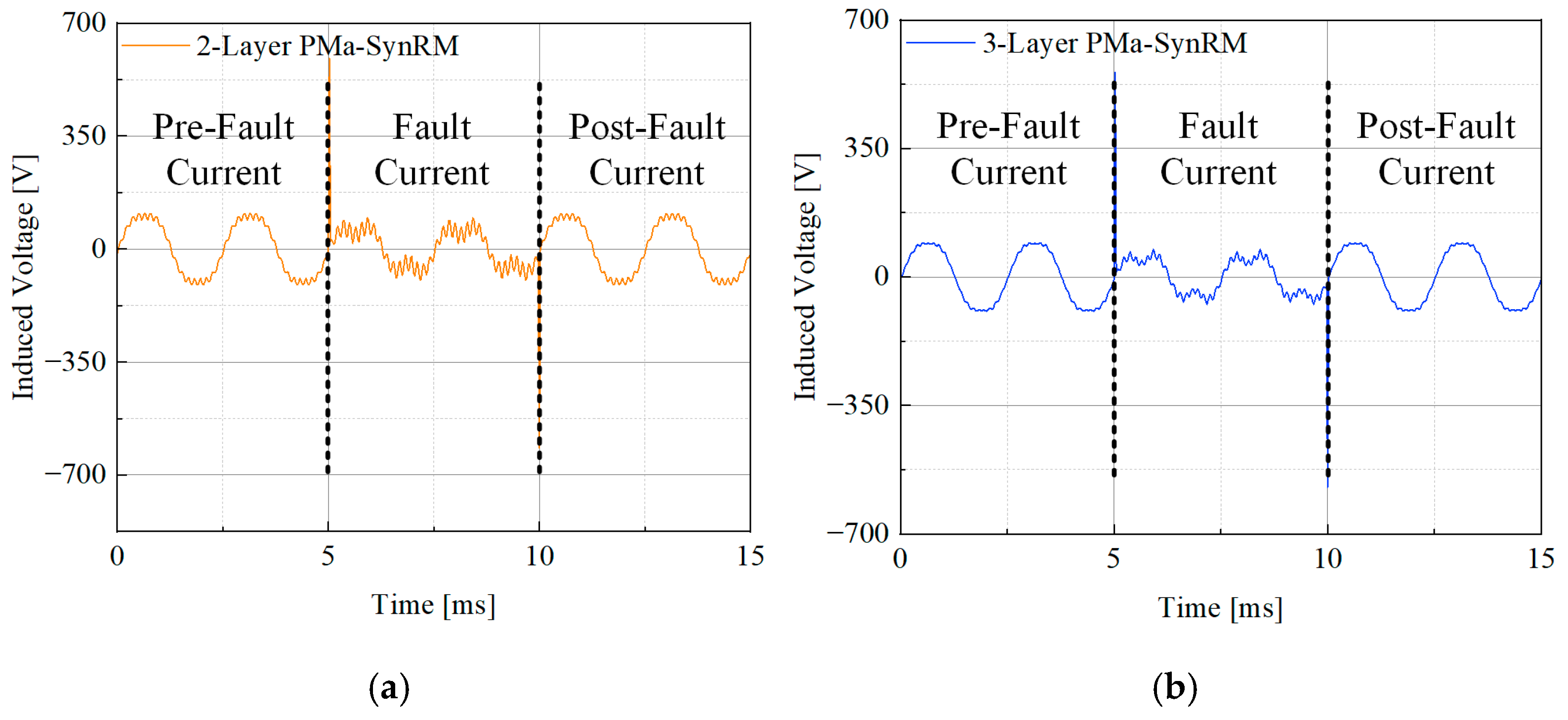
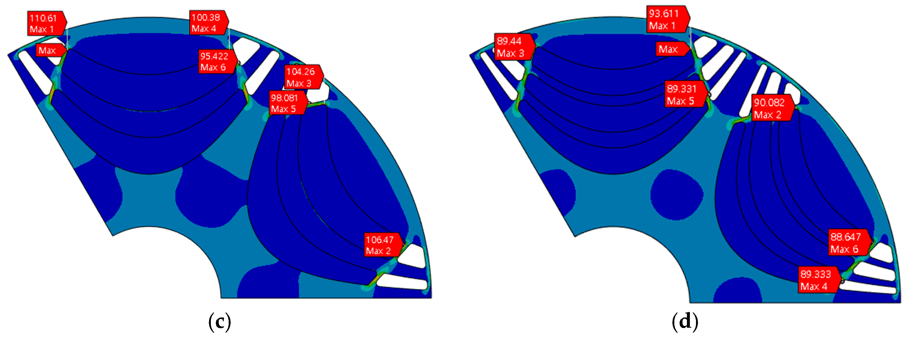
The irreversible demagnetization and rotor stiffness of the final designed two-layer and three-layer PMa-SynRMs were analyzed. Figure 14 shows the demagnetization analysis results and rotor stress analysis results of the two models. Since the back-EMF reduction rate is less than 0.5% for both models, it can be considered that no demagnetization occurs when the analysis error is considered. In addition, since the SF of the rotor stress analysis results is 3 or higher for both models, it can be judged that there is no problem with the mechanical stiffness. Table 9 shows the back-EMF reduction rate, maximum rotor stress value, and SF of the two models. It can be seen that the maximum stress value is smaller in the three-layer model because the outer diameter of the rotor is smaller than that of the two-layer model, so the effect of centrifugal force is less.
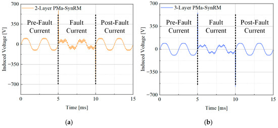
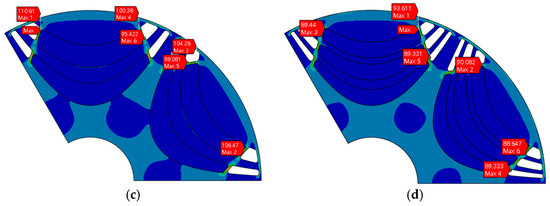
Figure 14.
Comparison of final model performance of 2-layer and 3-layer PMa-SynRMs: (a) 2-layer, (b) 3-layer model demagnetization analysis results; (c) 2-layer, (d) 3-layer stress analysis results.

Table 9.
Results of irreversible demagnetization and rotor stress analysis for the optimized models.
5.3. Experimental Validation
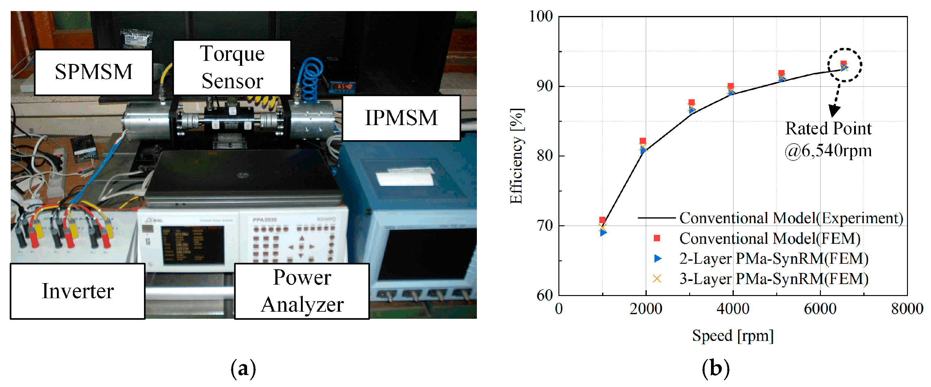
Figure 15a illustrates the experimental setup for the reference model. As shown in Figure 15b, the speed–efficiency curves obtained experimentally and via FEM simulation are in close agreement, thereby validating the reliability of the simulation results. The FEM analyses of the designed two-layer and three-layer PMa-SynRM models likewise demonstrate comparable accuracy. Future work will include experimental tests on these models to further confirm the validity of the simulation predictions.
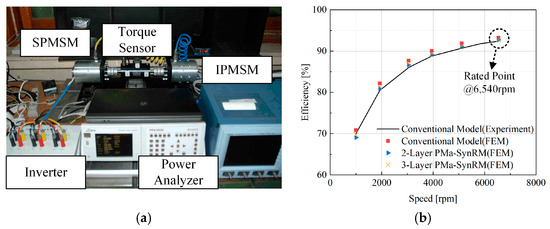
Figure 15.
Experimental validation: (a) experimental setup of the reference IPMSM, (b) comparison of measured and FEM-predicted speed–efficiency curves.
5.4. Techno-Economic Cost Analysis of Nd-Based vs. SmFeN-Based Designs
The conventional IPMSM and the proposed two-layer and three-layer PMa-SynRM models are compared from both technical and economic perspectives. Technically, Nd2Fe14B magnets are fabricated by compressing fine alloy powder into a green body, followed by high-temperature sintering. This method requires additional machining to form complex geometries and results in significant material loss due to scrap generation [60]. In contrast, the Sm2Fe17N3 bonded magnets used in this study are manufactured by injection molding, where magnetic powder is mixed with a thermoplastic polymer binder and directly shaped into the rotor. This process minimizes post-processing even for intricate geometries and reduces material waste, which contributes to lower processing costs in high-volume production [61].
Table 10 compares the magnet usage and the total cost considering only the raw material prices of the conventional model and the two proposed models. From an economic standpoint, the two-layer and three-layer PMa-SynRM designs use approximately 2.3 and 2.2 times more magnet material than the conventional IPMSM, respectively. However, when considering only the raw material costs, the total motor cost of both PMa-SynRM designs is approximately 50 percent of the cost of the conventional model [61,62,63]. This cost advantage is attributed to the reduced need for secondary machining and the simplified manufacturing process based on powder and binder materials, which improves overall cost competitiveness.

Table 10.
Comparison of magnet mass and estimated total cost based on raw material prices for conventional IPMSM and proposed 2-layer and 3-layer PMa-SynRM designs.
6. Conclusions
This study presented the design and multi-objective optimization of an HRE-free PMa-SynRM for compressor applications using Sm-series injection-molded magnets. By leveraging the high shape flexibility of injection-molded magnets, a curved multi-layer flux-barrier rotor was developed based on the Joukowski airfoil potential to improve magnetic flux guidance. Comprehensive analyses of electromagnetic performance, irreversible demagnetization characteristics, and rotor mechanical stress were conducted to derive optimized two-layer and three-layer PMa-SynRM models.
To mitigate irreversible demagnetization, vulnerable magnet regions were selectively removed, and torque density was maintained by adjusting AR and SR. However, this resulted in increased torque ripple and greater magnet usage compared to the conventional IPMSM.
Among the two configurations, the three-layer PMa-SynRM demonstrated superior performance in terms of lower torque ripple, improved rotor stiffness, and enhanced demagnetization resistance, making it more suitable for high-reliability compressor drives.
In addition to technical advantages, the proposed designs offer significant economic benefits. Although the PMa-SynRMs require approximately twice the magnet mass compared to the conventional IPMSM, the total motor cost based solely on raw material prices is reduced by approximately 50%. This cost reduction is attributed to the use of bonded magnets and the injection molding process, which minimizes machining losses and simplifies manufacturing.
Future work will focus on prototype fabrication and experimental validation to confirm the FEM predictions. Additional optimization will target torque ripple reduction and further minimization of magnet usage, aiming to improve both efficiency and cost competitiveness of HRE-free PMa-SynRMs for industrial applications.
Author Contributions
Conceptualization, K.-H.S., J.-Y.C. and S.-M.K.; methodology, K.-H.S., Y.-T.C., J.-B.P. and J.-Y.C.; software, J.-H.J., Y.-S.K., S.-W.K. and S.-J.L.; validation, D.-H.L., K.-H.S., Y.-T.C. and J.-Y.C.; writing—original draft preparation, K.-H.S., Y.-T.C. and J.-Y.C.; writing—review and editing, D.-H.L., K.-H.S. and J.-Y.C.; supervision, J.-Y.C. and K.-H.S.; funding acquisition, D.-H.L., J.-Y.C. and K.-H.S. All authors have read and agreed to the published version of the manuscript.
Funding
This work was supported by the Korea Institute of Planning and Evaluation for Technology in Food, Agriculture and Forestry (IPET) through the Agriculture and Food Convergence Technologies Program for Research Manpower Development, funded by the Ministry of Agriculture, Food and Rural Affairs (MAFRA) (project No. RS-2024-00397026), and was conducted as part of the Glocal University Project, supported by the RISE (Regional Innovation System & Education) program funded by the Ministry of Education.
Data Availability Statement
The original contributions presented in this study are included in the article. Further inquiries can be directed to the corresponding author.
Conflicts of Interest
The authors declare no conflicts of interest.
Abbreviations
The following abbreviations are used in this manuscript:
| PMa-SynRM | Permanent-Magnet-Assisted Synchronous Reluctance Motor |
| IPMSM | Interior Permanent Magnet Synchronous Motor |
| PM | Permanent Magnet |
| HRE | Heavy Rare Earth |
| FEM | Finite Element Method |
| EA | Evolutionary Algorithm |
| SF | Safety Factor |
| SR | Split Ratio |
| AR | Aspect Ratio |
References
- Zhu, S.; Hu, Y.; Liu, C.; Jiang, B. Shaping of the Air Gap in a V-Typed IPMSM for Compressed-Air System Applications. IEEE Trans. Magn. 2021, 57, 8103705. [Google Scholar] [CrossRef]
- Tao, X.; Takemoto, M.; Tsunata, R.; Ogasawara, S. Novel Rotor Structure Employing Large Flux Barrier and Disproportional Airgap for Enhancing Efficiency of IPMSM Adopting Concentrated Winding Structure. IEEE Access 2023, 11, 2848–2862. [Google Scholar] [CrossRef]
- Hao, Z.; Yang, Y.; Tian, Y.; Gong, Y.; Zhang, C.; Song, H.; Hao, Z.; Zhang, J. Phase Lead Compensation of a Phase-Locked Loop in an IPMSM for Air-Conditioner Compressors. IEEE Trans. Energy Convers. 2021, 36, 1090–1100. [Google Scholar] [CrossRef]
- Xu, R.; Shen, X.; Lin, X.; Liu, Z.; Xu, D.; Liu, J. Robust Model Predictive Control of Position Sensorless-Driven IPMSM Based on Cascaded EKF-LESO. IEEE Trans. Transp. Electrif. 2025, 11, 8824–8832. [Google Scholar] [CrossRef]
- Lin, X.; Liu, J.; Liu, Z.; Gao, Y.; Peretti, L.; Wu, L. Model-Free Current Predictive Control for PMSMs with Ultralocal Model Employing Fixed-Time Observer and Extremum-Seeking Method. IEEE Trans. Power Electron. 2025, 40, 10682–10693. [Google Scholar] [CrossRef]
- Zhang, Y.; Wu, Z.; Yan, Q.; Huang, N.; Du, G. An Improved Model−Free Current Predictive Control of Permanent Magnet Synchronous Motor Based on High−Gain Disturbance Observer. Energies 2023, 16, 141. [Google Scholar] [CrossRef]
- Yoshida, Y.; Yoshida, R.; Sakurai, S.; Abe, M.; Tada, S.; Yamamoto, M.; Tajima, K. Study on Orientation and Magnetization Characteristics of Injection-Molded IPMSM Using Sm-Fe-N Bonded Magnets. In Proceedings of the IEEE Industry Applications Society Annual Meeting (IAS), Taipei, Taiwan, 15–20 June 2025; pp. 1–5. [Google Scholar]
- Yoshida, Y.; Yoshida, R.; Uwano, T.; Sakurai, S.; Abe, M.; Tada, S.; Yamamoto, M.; Tajima, K. Evaluation of an IPMSM Featuring a Rotor Core Directly Injection-Molded with Sm-Fe-N Bonded Magnets. In Proceedings of the 27th International Conference on Electrical Machines and Systems (ICEMS), Fukuoka, Japan, 26–29 November 2024; pp. 2636–2639. [Google Scholar]
- Kim, K.-O.; Jung, Y.-H.; Park, J.-C.; Lim, M.-S. Comparative Study of Mechanical and Electrical Characteristics of High-Strength and Conventional Electrical Steel for EV Traction High-Speed Multilayer IPMSM Using Rare-Earth Free PM. IEEE Trans. Magn. 2023, 59, 8102205. [Google Scholar] [CrossRef]
- Jung, Y.-H.; Park, M.-R.; Kim, K.-O.; Chin, J.-W.; Hong, J.-P.; Lim, M.-S. Design of High-Speed Multilayer IPMSM Using Ferrite PM for EV Traction Considering Mechanical and Electrical Characteristics. IEEE Trans. Ind. Appl. 2021, 57, 327–339. [Google Scholar] [CrossRef]
- Kazemisangdehi, S.; Zhu, Z.Q.; Zhou, Y.; Chen, L.; Yang, L. Series Hybrid Rare-Earth and Ferrite Magnets Delta-Shape IPMSM with Split Ferrite Spoke. IEEE Trans. Ind. Appl. 2025, 1–12, early access. [Google Scholar] [CrossRef]
- Poudel, B.; Amiri, E.; Rastgoufard, P.; Mirafzal, B. Toward Less Rare-Earth Permanent Magnet in Electric Machines: A Review. IEEE Trans. Magn. 2021, 57, 900119. [Google Scholar] [CrossRef]
- Tahanian, H.; Aliahmadi, M.; Faiz, J. Ferrite Permanent Magnets in Electrical Machines: Opportunities and Challenges of a Non-Rare-Earth Alternative. IEEE Trans. Magn. 2020, 56, 900120. [Google Scholar] [CrossRef]
- Kobayashi, M.; Morimoto, S.; Sanada, M.; Inoue, Y. Performance Comparison between PMASynRM with Dy-Free Bonded Magnets and IPMSM with Sintered Magnets for Automotive Applications under Various Temperature Conditions. In Proceedings of the 21st European Conference on Power Electronics and Applications (EPE ‘19 ECCE Europe), Genova, Italy, 3–5 September 2019; pp. 1–9. [Google Scholar]
- Kobayashi, M.; Morimoto, S.; Sanada, M.; Inoue, Y. Basic Study of PMASynRM with Bonded Magnet for Automotive Applications. In Proceedings of the 2018 International Power Electronics Conference (IPEC), Niigata, Japan, 20–24 May 2018; pp. 2802–2807. [Google Scholar]
- Xing, F.; Zhang, J.; Zuo, F.; Gao, Y. Optimization of an Asymmetric-Rotor Permanent Magnet-Assisted Synchronous Reluctance Motor for Improved Anti-Demagnetization Performance. Appl. Sci. 2024, 14, 11233. [Google Scholar] [CrossRef]
- Chuang, T.-S. A high-efficiency PM-assisted synchronous reluctance motor drive. In Proceedings of the IEEE Applied Power Electronics Conference and Exposition (APEC), Long Beach, CA, USA, 17–21 March 2013; pp. 3180–3185. [Google Scholar]
- Zhao, W.; Xing, F.; Wang, X.; Lipo, T.A.; Kwon, B.I. Design and Analysis of a Novel PM-Assisted Synchronous Reluctance Machine with Axially Integrated Magnets by the Finite-Element Method. IEEE Trans. Magn. 2017, 53, 8104104. [Google Scholar] [CrossRef]
- Liu, C.-T.; Luo, T.Y.; Shih, P.C.; Yen, S.C.; Lin, H.N.; Hsu, Y.W.; Hwang, C.C. On the Design and Construction Assessments of a Permanent-Magnet-Assisted Synchronous Reluctance Motor. IEEE Trans. Magn. 2017, 53, 2002104. [Google Scholar]
- Kong, Y.; Nicola, B.; Lin, M. Loss Functions and Efficiency Model of Permanent Magnet Assisted Synchronous Reluctance Machine. IEEE Trans. Energy Convers. 2023, 38, 53–63. [Google Scholar] [CrossRef]
- Cho, S.-K.; Jung, K.-H.; Choi, J.-Y. Design optimization of interior permanent magnet synchronous motor for electric compressors of air-conditioning systems mounted on EVs and HEVs. IEEE Trans. Magn. 2018, 54, 8204705. [Google Scholar] [CrossRef]
- Shin, H.-J.; Choi, J.-Y.; Cho, H.-W.; Jang, S.-M. Analysis on electromagnetic vibration source permanent magnet synchronous motor for compressor of electric vehicles. In Proceedings of the 2012 IEEE Vehicle Power and Propulsion Conference (VPPC), Seoul, Republic of Korea, 9–12 October 2012; pp. 200–203. [Google Scholar]
- Kobayashi, M.; Morimoto, S.; Sanada, M.; Inoue, Y. Investigation of PMASynRM with Dy-Free Bonded Magnets for Traction Applications Considering Irreversible Demagnetization. In Proceedings of the IEEE Energy Conv. Congress & EXPO (ECCE), Portland, OR, USA, 23–27 September 2018; pp. 1627–1632. [Google Scholar]
- Minoru, K. Reluctance Motor. Japan Patent JP 2004/096909 A, 25 March 2004. [Google Scholar]
- Germishuizen, J.J.; Van der Merwe, F.S.; Van der Westhuizen, K.; Kamper, M.J. Performance comparison of reluctance synchronous and induction traction drives for electrical multiple units. In Proceedings of the IEEE Industry Applications Conference, Conference Record, Rome, Italy, 8–12 October 2000; Volume 1, pp. 316–323. [Google Scholar]
- Moghaddam, R.R. Synchronous Reluctance Machine (SynRM) Design. Master’s Thesis, Royal Institute of Technology (KTH), Stockholm, Sweden, 2007. [Google Scholar]
- Kostko, J.K. Polyphase reaction synchronous motors. J. Am. Inst. Electr. Eng. 1923, 42, 1162–1168. [Google Scholar] [CrossRef]
- Uberti, F.; Frosini, L.; Szabó, L. A New Design Procedure for Rotor Laminations of Synchronous Reluctance Machines with Fluid Shaped Barriers. Electronics 2022, 11, 134. [Google Scholar] [CrossRef]
- Rajabi Moghaddam, R. Synchronous Reluctance Machine (SynRM) in Variable Speed Drives (VSD) Applications. Ph.D. Thesis, KTH Royal Institute of Technology, Stockholm, Sweden, 2011. [Google Scholar]
- Wang, Y.; Bacco, G.; Bianchi, N. Geometry Analysis and Optimization of PM-Assisted Reluctance Motors. IEEE Trans. Ind. Appl. 2017, 53, 4338–4347. [Google Scholar] [CrossRef]
- Mathews, J.H.; Howell, R.W. Complex Analysis for Mathematics and Engineering, 4th ed.; Jones and Bartlett Publishers: Sudbury, MA, USA, 2001; ISBN 0-7637-1425-9. [Google Scholar]
- Binns, K.J.; Lawrenson, P.J. The Analytical and Numerical Solution of Electric and Magnetic Fields; Wiley: Hoboken, NJ, USA, 1992. [Google Scholar]
- Wilson, R.; Kumar, P.; El-Refaie, A. Minimization of Rare-Earth Permanent Magnets and Demagnetization Risk in PM-assisted Synchronous Reluctance Motor with Blended Magnets. In Proceedings of the IEEE Energy Conversion Congress and Exposition (ECCE), Nashville, TN, USA, 29 October–2 November 2023; pp. 4257–4264. [Google Scholar]
- Kumar, P.; Wilson, R.; Chowdhury, T.; El-Refaie, A. Electromagnetic and Mechanical Design Optimization of High-Speed PMASynRM Utilizing Different Magnet Combinations for EV Application. In Proceedings of the International Conference on Electrical Machines (ICEM), Torino, Italy, 1–4 September 2024; pp. 1–7. [Google Scholar]
- Lin, D.; Zhou, P.; Bracken, E. Generalized Algorithm to Deal with Temperature-Dependent Demagnetization Curves of Permanent Magnets for FEA. IEEE Trans. Magn. 2021, 57, 7402706. [Google Scholar] [CrossRef]
- Jeong, J.; Lee, H.; Orviz, M.; Bin Lee, S.; Reigosa, D.; Briz, F. Detection of Trailing Edge PM Demagnetization in Surface PM Synchronous Motors. IEEE Trans. Ind. Appl. 2023, 59, 3390–3399. [Google Scholar] [CrossRef]
- Rao, D.; Bagianathan, M. Selection of Optimal Magnets for Traction Motors to Prevent Demagnetization. Machines 2021, 9, 124. [Google Scholar] [CrossRef]
- Al-Qarni, A.; El-Refaie, A. Optimum Rotor Design for Rare-Earth Free High Performance Traction Applications Interior Permanent Magnet Motors Enabled by Iron Nitride Permanent Magnet. In Proceedings of the IEEE International Electric Machines & Drives Conference (IEMDC), San Francisco, CA, USA, 15–18 May 2023; pp. 1–7. [Google Scholar]
- Kang, D.-W. Analysis of Vibration and Performance Considering Demagnetization Phenomenon of the Interior Permanent Magnet Motor. IEEE Trans. Magn. 2017, 53, 8210807. [Google Scholar] [CrossRef]
- Al-Qarni, A.; El-Refaie, A. Design and Optimization of High-Performance Rare-Earth Free Interior Permanent Magnet Motors for Electric Vehicles Enabled by Iron Nitride Magnets. In Proceedings of the Energy Conversion Congress and Exposition (ECCE), Nashville, TN, USA, 29 October–November 2023; pp. 4082–4089. [Google Scholar]
- Yoon, K.-Y.; Hwang, K.-Y. Optimal Design of Spoke-Type IPM Motor Allowing Irreversible Demagnetization to Minimize PM Weight. IEEE Access 2021, 9, 65721–65729. [Google Scholar] [CrossRef]
- Hwang, K.-Y.; Yoon, K.-Y. Fault-Tolerant Design Process of Spoke-Type IPM Motor Considering Irreversible Demagnetization of PM in Integrated Electric Brake System. IEEE Trans. Magn. 2022, 58, 8206809. [Google Scholar] [CrossRef]
- Ni, R.; Xu, D.; Wang, G.; Ding, L.; Zhang, G.; Qu, L. Maximum efficiency per ampere control of permanent-magnet synchronous machines. IEEE Trans. Ind. Electron. 2015, 62, 2135–2143. [Google Scholar] [CrossRef]
- Yamazaki, K.; Kumagai, M. Torque analysis of interior permanent magnet synchronous motors by considering cross-magnetization: Variation in torque components with permanent-magnet configurations. IEEE Trans. Ind. Electron. 2014, 61, 3192–3201. [Google Scholar] [CrossRef]
- Wang, K.; Zhu, Z.Q.; Ombach, G.; Chlebosz, W. Average torque improvement of interior permanent-magnet machine using third harmonic in rotor shape. IEEE Trans. Ind. Electron. 2014, 61, 5047–5057. [Google Scholar] [CrossRef]
- Chai, F.; Li, Y.; Liang, P.; Pei, Y. Calculation of the Maximum Mechanical Stress on the Rotor of Interior Permanent-Magnet Synchronous Motors. IEEE Trans. Ind. Electron. 2016, 63, 3420–3432. [Google Scholar] [CrossRef]
- Barcaro, M.; Meneghetti, G.; Bianchi, N. Structural Analysis of the Interior PM Rotor Considering Both Static and Fatigue Loading. IEEE Trans. Ind. Appl. 2014, 50, 253–260. [Google Scholar] [CrossRef]
- Lee, S.-J.; Nguyen, M.-D.; Kwak, K.-W.; Kim, T.-S.; Eom, S.-H.; Choi, Y.-T.; Kim, Y.-J.; Shin, K.-H.; Choi, J.-Y. Characteristic Analysis and Improved Design of IPMSM for Automotive Compressor Through Tapering of Rotor Surface. IEEE Trans. Magn. 2025, 61, 8203105. [Google Scholar] [CrossRef]
- Chu, G.; Dutta, R.; Rahman, M.F.; Lovatt, H.; Sarlioglu, B. Analytical calculation of maximum mechanical stress on the rotor of interior permanent-magnet synchronous machines. IEEE Trans. Ind. Appl. 2019, 56, 1321–1331. [Google Scholar] [CrossRef]
- Wang, Y.; Fang, H.; Li, D.; Qu, R. Calculation of the Rotor Mechanical Stress of Bridgeless Interior Permanent-Magnet Synchronous Machines with a High-Strength Sleeve. In Proceedings of the IEEE 26th International Conference on Electrical Machines and Systems (ICEMS), Zhuhai, China, 5–8 November 2023; pp. 185–190. [Google Scholar]
- Sahu, A.; Abdelrahman, A.; Al-Ani, D.; Bilgin, B. Fatigue life calculation and mitigation of bridge stresses in the rotor core of a delta-shape interior permanent magnet motor. In Proceedings of the IEEE Transportation Electrification Conference & Expo (ITEC), Chicago, IL, USA, 21–25 June 2021; pp. 1–6. [Google Scholar]
- Chu, G.; Dutta, R.; Xiao, D.; Fletcher, J.E.; Rahman, M.F. Development and optimization of a mechanically robust novel rotor topology for very-high-speed IPMSMs. IEEE Trans. Energy Convers. 2023, 38, 1781–1792. [Google Scholar] [CrossRef]
- Monissen, C.; Arslan, M.E.; Krings, A.; Andert, J. Mechanical stress in rotors of permanent magnet machines—Comparison of different determination methods. Energies 2022, 15, 9169. [Google Scholar] [CrossRef]
- De Jong, K.A. Evolutionary Computation: A Unified Approach; MIT Press: Cambridge, MA, USA; London, UK, 2006. [Google Scholar]
- Eiben, A.E.; Smith, J.E. Introduction to Evolutionary Computing; Springer: Berlin/Heidelberg, Germany, 2003. [Google Scholar]
- Vikhar, P.A. Evolutionary algorithms: A critical review and its future prospects. In Proceedings of the International Conference on Global Trends in Signal Processing, Information Computing and Communication (ICGTSPICC), Jalgaon, India, 22–24 December 2016; pp. 261–265. [Google Scholar]
- Yu, C.; Qu, R.; Xu, W.; Li, J. Analytical determination of optimal split ratio for interior permanent magnet synchronous motor. In Proceedings of the IEEE Conference and Expo Transportation Electrification Asia-Pacific (ITEC Asia-Pacific), Beijing, China, 31 August–3 September 2014; pp. 1–5. [Google Scholar]
- Hong, H.; Lee, J.-K.; Jung, D.-H.; Lee, J.; Kim, H. Comparative Study on Electromagnetic Performance of Slotted and Slotless PM Synchronous Motors According to Aspect Ratios. IEEE Trans. Magn. 2025, 61, 8201604. [Google Scholar] [CrossRef]
- Tsunata, R.; Takemoto, M.; Imai, J.; Saito, T.; Ueno, T. Comparison of Thermal Characteristics in Various Aspect Ratios for Radial-Flux and Axial-Flux Permanent Magnet Machines. IEEE Trans. Ind. Appl. 2023, 59, 3353–3367. [Google Scholar] [CrossRef]
- Cui, J.; Ormerod, J.; Parker, D.; Ott, R.; Palasyuk, A.; Mccall, S.; Paranthaman, M.P.; Kesler, M.S.; McGuire, M.A.; Nlebedim, I.C.; et al. Manufacturing Processes for Permanent Magnets: Part I—Sintering and Casting. JOM 2022, 74, 1279–1295. [Google Scholar] [CrossRef]
- Wang, H.; Lamichhane, T.N.; Paranthaman, M.P. Review of additive manufacturing of permanent magnets for electrical machines: A prospective on wind turbine. Mater. Today Phys. 2022, 24, 100675. [Google Scholar] [CrossRef]
- Kitco—Base Metals Prices. Available online: https://www.kitco.com/price/base-metals (accessed on 8 August 2025).
- Metal.com—Cold-Rolled Non-Oriented Silicon Steel–B35A250–0.35*1200*C–Shanghai–Baosteel. Available online: https://www.metal.com/en/prices/202403290002 (accessed on 8 August 2025).
Disclaimer/Publisher’s Note: The statements, opinions and data contained in all publications are solely those of the individual author(s) and contributor(s) and not of MDPI and/or the editor(s). MDPI and/or the editor(s) disclaim responsibility for any injury to people or property resulting from any ideas, methods, instructions or products referred to in the content. |
© 2025 by the authors. Licensee MDPI, Basel, Switzerland. This article is an open access article distributed under the terms and conditions of the Creative Commons Attribution (CC BY) license (https://creativecommons.org/licenses/by/4.0/).

