Abstract
This paper presents a novel four-dimensional (4D) memristive system, notable for its simplicity and unique dynamic behaviors. Comprising only seven terms and devoid of equilibrium points, this system is capable of generating hidden attractors. A comprehensive analysis of its dynamic properties is conducted, including Lyapunov exponents, Kaplan–Yorke dimensions, temporal diagrams and phase portraits, multistability, and offset boosting. Numerical simulations over a sufficiently long time interval show that the Lyapunov function remains bounded, thereby confirming the dissipative nature and global stability of the newly proposed 4D hyperchaotic system. The theoretical model is further validated through electronic simulations of the chaotic system using Multisim software. Additionally, the paper explores synchronization between two identical 4D hyperchaotic systems. The proposed system, despite its structural simplicity, exhibits intricate chaotic dynamics, making it suitable for various practical applications. In particular, a method for chaotic encryption and decryption of an information signal was developed and validated through numerical testing. Based on the method of complete synchronization of chaotic systems, the possibility of detecting a weak signal is demonstrated. The proposed system is also implemented on an Arduino UNO to demonstrate its practical applicability for real-time chaotic signal generation and image encryption.
Keywords:
hyperchaotic behavior; synchronization; memristor; circuit implementation; secure communication; weak signal detection; Arduino UNO implementation MSC:
34A34; 34D45; 70K50; 93C40
1. Introduction
Recent advances in chaos theory have significantly expanded its scope of applications, making it an integral tool in diverse engineering and scientific domains. Its influence spans secure communications [1], cryptographic systems [2,3], medicine [4], neural and genetic networks [5,6], and memristive systems [7], among other fields.
Lorenz’s discovery of a three-dimensional (3D) chaotic system [8] has sparked extensive exploration into the behavior and properties of various chaotic systems. To exhibit chaotic behavior, a dynamic system must include at least five terms. Systems at this threshold of simplicity are notably rarer than those with six or more terms. Their algebraic elegance not only makes them attractive but also minimizes the number of electronic components required for circuit implementation. Sprott pioneered the introduction of several five-term chaotic systems [9], followed by contributions from Van der Schrier and Maas [10], Elwakil et al. [11], Toncharoen and Srisuchinwong [12], and Munmuangsaen and Srisuchinwong [13]. However, despite these advances, the past decade has seen only a modest number of novel five-term chaotic attractors proposed [14,15,16]. For example, Chang and Kim [14] introduced a chaotic five-term system with one multiplier, one quadratic term, and one absolute value term. Another study by Tamba et al. [15] presented a new 3D five-term chaotic system distinguished by hyperbolic sinusoidal nonlinearity and the absence of equilibrium points. Furthermore, Gokyildirim et al. [16] described a new five-term 3D chaotic flow characterized by cubic nonlinearity, a linear term, a constant term, and two other nonlinear components.
However, chaos researchers have increasingly shifted their focus towards dynamic systems with dimensions greater than three, particularly hyperchaotic systems, which display more intricate and complex dynamics compared to standard chaotic systems. The defining feature of hyperchaotic systems is the presence of multiple positive Lyapunov exponents (LEs), indicating a higher degree of unpredictability. Specifically, a four-dimensional (4D) autonomous hyperchaotic system is characterized by two positive Lyapunov exponents, one zero exponent, and one negative exponent [17]. In this context, there is a growing trend to develop new chaotic and hyperchaotic models that address the following objectives:
- (1)
- Ensuring the presence of multiple positive Lyapunov exponents;
- (2)
- Minimizing the number of terms in the system for simplicity;
- (3)
- Maximizing the Kaplan–Yorke dimension to achieve higher system complexity.
Chua’s groundbreaking discovery of the memristor [18]—a device that couples electric charge and magnetic flux, effectively functioning as a resistor with memory, has proven instrumental in tackling these challenges, enabling the design of more efficient and sophisticated chaotic and hyperchaotic systems. Numerous chaotic and hyperchaotic systems that incorporate memristors as nonlinear elements have been developed, demonstrating the versatility of memristors in generating complex dynamics. In addition, various equivalent circuits for modeling memristor emulators have been extensively explored in the literature [19].
In this work, we focus specifically on 4D chaotic systems that integrate memristors, leveraging their unique properties to enhance system behavior and complexity. Pham et al. [20] introduced a 4D memristive system comprising 12 terms, 5 of which are nonlinear. This system is particularly notable for its lack of equilibrium points and its ability to exhibit periodic, chaotic, and hyperchaotic dynamics within specific parameter ranges. Rajagopal et al. [21] proposed another 4D memristive system where the equilibrium structure is dependent on a control parameter, allowing for either no equilibrium or an equilibrium line. By varying this parameter, the system transitions between chaotic and hyperchaotic behavior. This system includes 11 terms, 5 of which are non-linear. Singh et al. [22] presented a simpler 4D chaotic memristor-based system without equilibria, featuring only 9 terms, including two nonlinear ones. An even more compact design was introduced by Tamba et al. [23], who developed a 4D two-scroll chaotic memristive system with just 7 terms and three nonlinearities. This system exhibits diverse and complex dynamics, including offset boosting, remerging period-doubling bifurcations, and hidden extreme multi-stability. Irfan [24] proposed a 4D hyperchaotic hyperjerk memristive system characterized by a line equilibrium and containing seven algebraic terms with a single non-linearity. Remarkably, this system incorporates an intrinsic memristive nonlinearity, an inherent property of the memristor itself, making it a highly streamlined and elegant design.
This study presents a streamlined 4D seven-term system derived from a 3D five-term chaotic system incorporating a memristor. For ease of comparison, Table 1 presents the main characteristics of various 4D memristive chaotic systems, including the newly proposed one.

Table 1.
Comparison of 4D memristive chaotic systems based on their main characteristics.
The proposed hyperchaotic system, notable for its absence of equilibrium points and its ability to generate hidden attractors, features only three non-linear terms. This approach highlights the potential to construct new hyperchaotic dynamic systems from simpler 3D five-term chaotic systems, paving the way for the development of electronic chaos generators with increased complexity and functionality.
This manuscript is organized as follows. The introduction provides a concise overview of the current state of research and the problem addressed in this study. Section 2 details the derivation of a novel 4D hyperchaotic dynamical system that incorporates a memristor. Section 3 analyzes the dynamic properties of the proposed non-linear 4D system. This includes examining its fixed points, computing the Lyapunov spectrum and dimension, and investigating phenomena such as multistability and offset-boosting control. Section 4 focuses on implementing an electronic circuit for a hyperchaotic chaos generator using the Multisim environment. The circuit’s functionality is validated by comparing simulation results with those obtained through the Mathematica environment. Section 5 explores the numerical analysis of synchronization between two identical 4D hyperchaotic systems. Synchronization is achieved using the adaptive control method, as described in [25,26,27,28]. In Section 6, we apply adaptive synchronization of chaotic signals to secure communication. Section 7 covers the identification of weak signals using a new 4D hyperchaotic system. A method for detecting weak signals based on chaotic system synchronization is presented. The signal perturbs the master system, causing a loss of synchronization with the slave. The resulting synchronization error reveals the presence of a weak signal. In Section 8, the practical implementation of the newly introduced four-dimensional memristive hyperchaotic system is successfully achieved using the cost-effective and readily available Arduino UNO microcontroller. Conclusions summarize the key findings and contributions of this study.
2. A New 4D Memristive Dynamical System: Derivation and Key Properties
The primary objective in designing a new 4D dynamical system incorporating a memristor is to develop a model with minimal terms while still exhibiting complex behaviors, such as hidden attractors and hyperchaos. This section introduces a novel 4D memristive two-wing chaotic system consisting of only seven terms. This system is based on the model proposed in [13] and is defined as follows:
Here, a and b are positive constant parameters. The system (1) exhibits highly complex chaotic behavior when , and the initial conditions (ICs) are set to . In this case, the Lyapunov exponents for the system (1) are . Furthermore, the Lyapunov dimension of the system (1) is fractional, with a value of [13].
By adding a fourth state variable and connecting it to the original system through a memristor, the system (1) expands to a 4D system, producing hyperchaotic behavior. We use the absolute memristor model for simplicity, namely Bao’s magnetically controlled memristor [29], which is defined by the following equations:
The symbols , , and in equation (2) represent the input, output, and state variables of the memory device, respectively. Whereas and are constant coefficients, set to and , the function represents the magnetic flux. An origin-crossing smooth quadratic nonlinear characteristic curve is visible in the graph of the system (2). The memristor is powered by a sinusoidal AC voltage source, , which can be written as , where A and f stand for the amplitude and frequency of the external signal, respectively.
Figure 1 illustrates the memristor circuit in the simulation results, which show how it reacts to sinusoidal excitation with alternating current. A closed curve, more precisely, a hysteresis loop that passes through the origin, is formed by the memristor’s current-voltage characteristic. Interestingly, the area of the hysteresis loop shrinks with increasing frequency f, but expands with increasing amplitude A. This behavior is consistent with the fundamental properties of memristors.
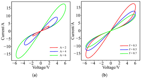
Figure 1.
Simulation results of the hysteresis loop for the memductance function : (a) different amplitude values A; (b) different values of frequency f.
A new set of 4D nonlinear dynamical equations based on memristor is produced by integrating the expressions (2) into the system of nonlinear dynamic equations in (1), as illustrated below:
In this formulation, we replace the flux notation with a new dynamic variable . The system (3) consists of seven terms, including four constant parameters and three nonlinear terms. In particular, it represents the minimum number of terms necessary to generate hyperchaotic dynamics in a four-dimensional autonomous system. Such a 4D system with only seven terms is uncommon in the literature, underscoring a key advantage of the proposed system (3).
3. Dynamical Analysis
In this section, we consider some of the basic dynamic characteristics of the new 4D dynamic system.
3.1. Symmetry and Dissipative
The system (3) is easily verifiable to be symmetric with respect to the -axis and to remain invariant under the following coordinate transformation :
In order to further describe the behavior of the system, the divergence or trace of the matrix of the system (3) is calculated as
Consequently, for all positive values of the parameters, the system (3) is dissipative.
3.2. Equilibrium Points
The suggested 4D system has no points of equilibrium. The equilibrium states of a dynamic system (3) are found by setting all in the system (3) and solving the system equations.
From the fourth equation, we find that . Substituting this value into the third equation yields a contradictory result, , indicating that the system has no equilibrium points. Consequently, all attractors generated by the system (3) are hidden attractors. The system’s attractors are regarded as hidden since they are not directly related to any of the system’s equilibrium points, including stable nodes, saddles, or foci. In particular, the attractors in this system are located in areas of phase space that lack equilibrium points, which makes it more difficult to detect them. For these attractors, standard methods, such as the Shil’nikov theorem [30], that frequently depend on perturbing trajectories close to equilibrium points are ineffective.
3.3. Lyapunov Exponents and Kaplan–Yorke Dimension
The system’s behavior depends on variations in multiple parameters, making multiparameter analysis a complex process. Therefore, it is preferable to study the system by varying a single parameter as a control parameter. The evolution of the system for varying values of the control parameter can be analyzed through the Lyapunov exponent spectrum, providing insights into its dynamic behavior and stability characteristics.
A deeper understanding of a dynamic system’s behavior under changes in a control parameter can be achieved by examining its Lyapunov exponents (LEs). These exponents represent the average exponential rates at which nearby trajectories in phase space diverge or converge. Analyzing the Lyapunov exponents provides insight into the system’s stability and the presence of chaotic behavior. A positive Lyapunov exponent (LE) indicates instability or chaos in the system. A negative LE indicates asymptotic stability, which may correspond to convergence toward an equilibrium point or a stable periodic orbit. Thus, by examining the signs of the LEs, we can classify the system’s behavior as quasi-regular (2-torus), chaotic, or hyperchaotic. We computed all Lyapunov exponents using a as a control parameter, with other parameters fixed at , and the initial conditions given by (7):
The dynamical behaviors (3) are classified as shown in Table 2.

Table 2.
Lyapunov exponents for different values of the parameter a.
From Table 2 we see examples of hyperchaos in system (3) for the parameter values and , respectively. The dissipative nature of the system (3) is confirmed by the fact that the sum of the six Lyapunov exponents is negative: . To evaluate the complexity of the attractors in the new hyperchaotic system (3), we calculate the Lyapunov dimension (or Kaplan–Yorke) for the parameter values and as follows:
where is determined from the conditions
Here, represents the count of the first nonnegative Lyapunov exponents in the spectrum. The dimension of (8) is fractional. We found that the Kaplan-Yorke dimension (8) is significantly higher than that of the chaotic system (1), indicating greater complexity in the dynamics of the system (3).
The dynamics of the Lyapunov exponents associated with hyperchaotic behavior for is illustrated in Figure 2.
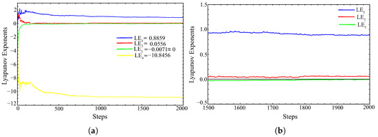
Figure 2.
Convergence plot of the Lyapunov exponents for system (3) with . (a) general view; (b) an enlarged inset, clearly demonstrating the presence of two positive Lyapunov exponents in the system, with the third exponent tending to zero.
The bifurcation diagram and the Lyapunov exponent spectrum concerning variations in the parameter a are depicted in Figure 3. These results indicate that system (3) exhibits chaotic and hyperchaotic regimes over a broad interval .
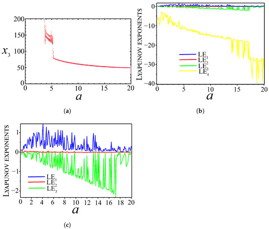
Figure 3.
(a) Bifurcation diagram; (b) spectra of all Lyapunov exponents; (c) spectra of the three Lyapunov exponents—all plotted versus parameter a.
3.4. Temporal Diagrams and Phase Portraits
Time diagrams provide a visual representation of how the state variables of a system evolve over time, effectively revealing oscillatory patterns, transient dynamics, or steady-state behavior. We plotted the temporal evolution of the state components for the hyperchaotic system (3), as illustrated in Figure 4.
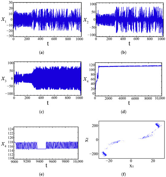
Figure 4.
Time diagrams. (a) the time diagram for the variable ; (b) the time diagram for the variable ; (c) the time diagram for the variable ; (d) the time diagram for the variable ; (e) the time diagram (an enlarged inset) for the variable ; (f) Poincaré section.
The time series of the variables exhibit an aperiodic structure, a hallmark feature of chaotic systems. An interesting behavior of the state variable is observed during computer simulations. The simulation time for the coordinate was extended to 10,000. As shown in Figure 4d, the amplitude of increases to approximately . Beyond this point (), the growth ceases and exhibits chaotic fluctuations within the range of roughly 114 to 118.
Phase portraits offer a geometric representation of the trajectories of a dynamical system in its state space, providing a clear visualization of chaotic attractors and their structure. Figure 5 also presents the solutions of Equation (3) with initial conditions (7), depicted as phase portraits of hidden attractors in the planes , , , , , and . The analysis of the Poincaré section concerning the plane shows that the trajectory densely fills a subset of the -plane, indicating the presence of chaotic dynamics (see Figure 4f). The scattered structure of points rules out periodic or quasiperiodic motion and supports the hypothesis of sensitive dependence on initial conditions. As illustrated in Figure 5, the dynamic variables () exceed the range supported by the power supply capabilities of the operational amplifiers. To address this limitation, the variables in the dynamical system (3) are rescaled as follows: . After applying this transformation, the hyperchaotic system (3) is reformulated as follows:
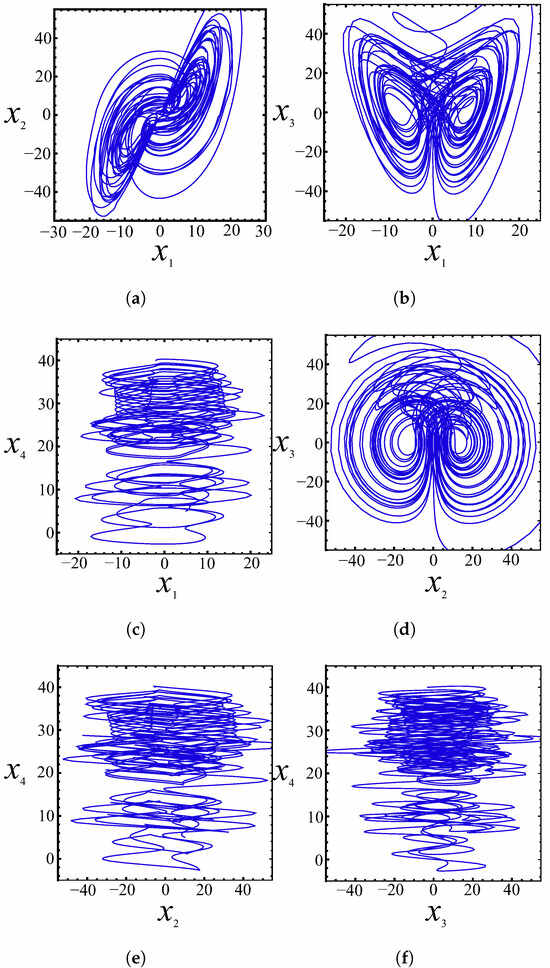
Figure 5.
Hidden attractors of the hyperchaotic system (3) for in various planes. (a) ; (b) ; (c) ; (d) ; (e) ; (f) .
3.5. Stability Analysis via the Lyapunov Function
The considered hyperchaotic system does not possess any equilibrium points, as the algebraic conditions for stationarity cannot be satisfied due to the nonlinear structure, particularly the non-smooth term in the first equation. In such systems, classical local linearization techniques become inapplicable, and stability analysis must rely on alternative global methods. A common approach involves the use of a Lyapunov function to investigate the boundedness and dissipativity of the system. Let us consider the following Lyapunov function:
which is a standard positive-definite energy-like function. Taking the time derivative along the trajectories of the system yields the following.
This expression is not sign-definite, but the presence of dominant negative quadratic terms and , together with a constant dissipative sink term , suggests that the energy function is dissipative on average. Although the remaining terms can be positive, they are linear and cannot offset the unbounded growth of the quadratic terms. We perform an upper bound estimation for the derivative of the Lyapunov function and show that it is bounded, which implies that the function itself remains bounded as well. We consider the absolute value of the derivative.
Assume that the trajectory is confined within a bounded region:
Then we obtain the following upper bound:
If the system starts in a region such that , we may take , which yields: . Therefore, the derivative of the Lyapunov function is bounded in magnitude by
Thus, the derivative is bounded and the Lyapunov function remains confined within a finite range. This supports the conclusion that the system is globally bounded and dissipative.
These theoretical findings are confirmed by numerical simulations (see Figure 6), where the Lyapunov function remains within finite bounds over a long time interval. This provides further evidence for the existence of a hidden attractor and supports the classification of the system as hyperchaotic, yet globally stable in the Lyapunov sense.
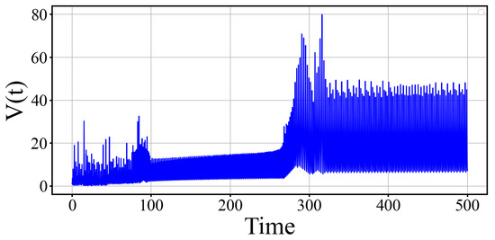
Figure 6.
Bounded evolution of the Lyapunov function , demonstrating dissipativity and global confinement of the system.
3.6. Sensitivity Analysis
In practical applications, understanding sensitivity limits becomes especially critical when modeling complex systems, ranging from climate models and biological populations to cryptographic algorithms and neural networks. The presence of two positive Lyapunov exponents in hyperchaotic systems significantly amplifies the sensitivity to initial conditions compared to conventional chaotic systems. This occurs because of an accelerated loss of predictability, as the forecasting time horizon diminishes much more rapidly. While for a system with one positive exponent the characteristic predictability time is approximately , for a hyperchaotic system with two exponents and the effective predictability time may be on the order of or even shorter, depending on the geometry of the phase space. This characteristic implies that infinitesimal perturbations in initial conditions can generate substantially divergent evolutionary pathways over time, making long-term forecasting fundamentally unreliable. Figure 7 illustrates the temporal evolution of the trajectories for the proposed hyperchaotic system (10) under two marginally different initial conditions. The trajectory corresponding to the nominal initial condition is depicted in blue, while the trajectory with the perturbed initial condition is shown in red. As evident in Figure 7, a marked divergence in the trajectory emerges after , demonstrating that the proposed system exhibits a marked sensitivity to the initial conditions.
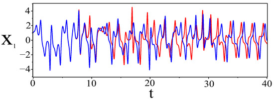
Figure 7.
This illustration demonstrates the sensitivity of the hyperchaotic system (10) to initial conditions. It is evident that the trajectories begin to diverge after .
3.7. Testing the Randomness of Chaotic Sequences
The randomness of chaotic sequences generated by the hyperchaotic system (10) with initial conditions (11) is evaluated using the NIST SP800-22 statistical test suite, implemented via a standard Python library.
Table 3 presents the results of all 15 core tests applied to a 10,000-bit sequence produced by system (10). According to the NIST criteria, a sequence passes a test if the corresponding p-value exceeds 0.01, indicating that the sequence exhibits sufficient randomness for that statistical property. If all tests are passed, the sequence is considered to possess good overall randomness characteristics [31].

Table 3.
Results of the NIST SP800-22 randomness tests for a 10,000-bit chaotic sequence.
3.8. Multistability and Offset Boosting Control
Multistability describes the phenomenon where two or more attractors coexist for the same set of system parameters but differ according to the initial conditions. The new hyperchaotic system (10) demonstrates this behavior, exhibiting coexisting attractors under varying initial conditions. Table 4 provides data for two different attractors obtained by solving system (10) with the same control parameters but different initial conditions. The behavior of these attractors, as detailed in Table 4, is visually depicted in Figure 8. To provide a more compelling illustration of multistability and the coexistence of attractors observed in the phase portraits of Figure 8, we employed the Poincaré section method. Among several sections tested, the plane with projection on the plane was found to be the most informative. This choice is justified by the fact that plays a crucial role in generating chaotic nonlinearity through the interaction term , as well as in the evolution equation for . Figure 9 shows the resulting Poincaré sections: the attractors corresponding to different initial conditions (listed in Table 4) are colored blue, while those generated from the same initial conditions are colored red. The clear separation of red and blue patterns highlights the coexistence of multiple attractors and demonstrates the pronounced sensitivity of the system to initial conditions.

Table 4.
The system (10) demonstrates multistability when using different ICs.
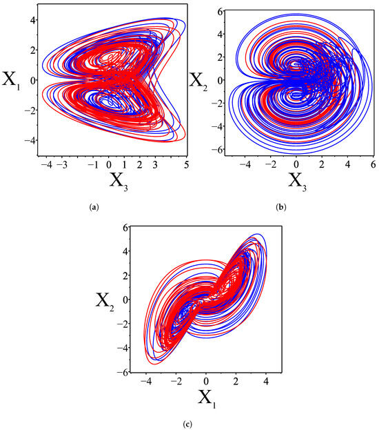
Figure 8.
Plots showing the multistability of two attractors in different phase planes for the initial conditions in Table 4. (a) ; (b) ; (c) .
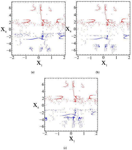
Figure 9.
Poincaré sections on showing coexistence of attractors: blue for initial conditions (a) , (b) , (c) ; red for .
Figure 9 shows the resulting Poincar’e sections: the attractors corresponding to different initial conditions (listed in Table 4) are colored blue, while those generated from the same initial conditions are colored red. The clear separation of red and blue patterns highlights the coexistence of multiple attractors and demonstrates the pronounced sensitivity of the system to initial conditions.
The offset boost control method proves to be a powerful tool for hyperchaotic systems, allowing attractors to be flexibly shifted in a desired direction by introducing an offset. This approach is particularly useful in engineering applications [32]. By adding a constant offset to specific system variables, chaotic signals can be manipulated across the phase space. In the equations of system (10), the state variable appears exclusively in the second equation, making it an ideal candidate for control. By replacing with , where k is a constant, we can directly influence this variable. As shown in Figure 10, for a positive value of , the attractor (green) moves in the negative direction, and for a negative value of , the attractor (red) moves in the positive direction. The attractor highlighted in blue corresponds to , which means that there is no change. The size of the attractor along the coordinate does not change for any constant value of k, as follows from the third equation of the system (10). However, along the coordinate , the attractor changes size. This is especially noticeable for the red attractor, since for negative k, the coordinate grows according to the second equation of the system (10). As demonstrated on the left side of Figure 10, adjusting the bias gain control k transitions the signal from bipolar to unipolar form. Furthermore, modifying k moves the attractor along the axis, as shown on the right side of Figure 10.
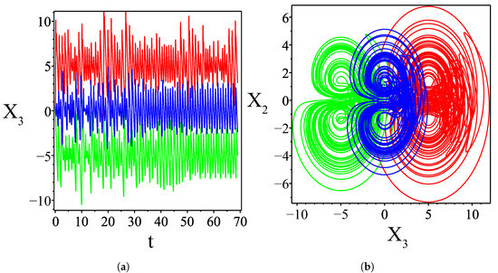
Figure 10.
The hyperchaotic system (3) for . (a) transition of the signal from bipolar to unipolar form as k is varied; (b) shift of the attractor along the axis as k is varied.
4. Electronic Circuit Implementation of the New Hyperchaotic System
In this section, we realize the theoretical model of the new hyperchaotic system (10) through the implementation of electronic circuits. By applying Kirchhoff’s laws, the electrical analog of system (10) is formulated as follows:
where is a stable DC voltage source to implement the constant (=9) in a system (10), are resistors , are voltage values, are capacitors and K is a scaling coefficient for the multiplier. We choose the normalized resistor as and the normalized capacitor as . Then the time constant is equal to s. We rescale the state variables of the system (18) as follows , , and . The Equation (18) can then be rewritten in a dimensionless form. By substituting , , and into (18) and comparing the numerical results with the output voltages of the system (10), the resistor values are determined as follows:
where
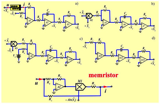
Figure 11.
Circuit modules implemented based on a system of equation (19): (a) , (b) , (c) , (d) and the memristor circuit module.
These circuits incorporate standard components, including resistors (R), capacitors (C), diodes – (1N4001), multipliers – (AD633), operational amplifiers – (TL084ACN), and a supply voltage of V. The constant 9 is achieved using a constant voltage source V. To implement the absolute value function , a standard electronic circuit [33] is used, as shown in Figure 12.
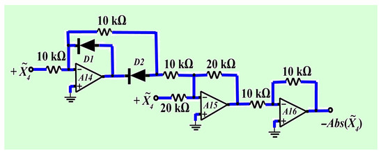
Figure 12.
Schematic diagram for the implementation of function .
The phase portraits in Figure 13 demonstrate a striking similarity between the Mathematica simulation results (Figure 5) and those obtained from Multisim (Figure 13).
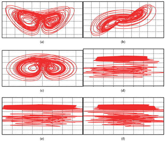
Figure 13.
Phase portraits of the new 4D hyperchaotic system as generated in Multisim oscilloscopes: (a) , (b) , (c) , (d) , (e) , (f) .
5. Control and Synchronization Mechanisms for a New Hyperchaotic System
Developing a new chaotic generator based on 4D nonlinear dynamical equations requires studying its synchronization capabilities to ensure practical application. This section explores the application of the adaptive control method [25,26,27,28] to synchronize two identical 4D hyperchaotic systems. Adaptive control of chaotic system synchronization provides robustness to parameter uncertainties and external disturbances, does not require precise knowledge of the master (or drive) system model, and enables effective synchronization even in high-dimensional and nonlinear systems. This makes the method particularly valuable for practical applications, including encryption, weak signal detection, and so on. The goal of complete synchronization is to use the master system’s output to control the slave (or response) system, ensuring that the slave system’s output asymptotically follows the master system’s output over time. Active feedback control is utilized when the system parameters are known and measurable, whereas adaptive feedback control is employed when the system parameters are uncertain or unknown.
5.1. Adaptive Control
This subsection introduces an adaptive controller to stabilize the novel 4D hyperchaotic system with unknown parameters. The novel controlled 4D chaotic system is expressed as follows:
where are the adaptive control inputs to be designed using estimates for the unknown parameters , respectively. The adaptive feedback control law is defined as follows:
The closed-loop control system is obtained by substituting (21) into (20), resulting in the following:
To simplify (22), the parameter estimation error is expressed as:
By incorporating (23), the closed-loop system (22) takes the following form:
Next, we introduce a Lyapunov function defined as:
which is a positive function of . Differentiating (25) concerning t, we obtain
From (26), the update law for the parameter estimates is derived as:
where on the symbol indicates the differentiation with respect to time t.
Theorem 1.
Proof.
Substituting the parameter update law (27) into (26), we obtain the time derivative of as
Then is a negative semidefinite function on . Integrating (28) from 0 to t, we get
where . Applying Barbalat’s lemma [34], it can be concluded that exponentially as for all initial conditions . This completes the proof.
We numerically solve systems (3) and (27) under the application of the adaptive control law (21). The parameter values for the 4D hyperchaotic system (3) are set as follows:
The control gains are chosen as
The initial values of the hyperchaotic system (20) are taken as
Also, as initial conditions for parameter estimates
□
Figure 14 illustrates the exponential convergence of the controlled states of the 4D hyperchaotic system (20).
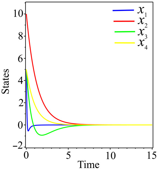
Figure 14.
Schematic diagram for the implementation of function .
5.2. Adaptive Synchronization
In this subsection, we consider the adaptive synchronization of two identical 4D systems with unknown system parameters. The system (3) serves as the drive system, while the following system is taken as the response (or slave) system:
Here, represent the signal variables of the slave system, and are the controllers designed to achieve global chaos synchronization between systems (3) and (30). The synchronization error between identical chaotic systems is defined as , for . The synchronization error dynamics are expressed as
The adaptive control law is formulated as follows.
where are positive constants that control the synchronization speed; , , , are estimates of unknown parameters , respectively. The parameter estimation errors are defined from (23). Substituting (32) into the error dynamics (31), we obtain
Now, consider the Lyapunov function defined by
Here is a quadratic positive definite function and differentiating it with respect to t, we find
We define the parameter update law as follows.
Theorem 2.
Proof.
According to the Lyapunov stability theory, it follows that if is a positive definite function and is a negative semidefinite function. Substituting the parameter update law (36) into (35), we obtain the time derivative of as:
Integrating (37) from 0 to t, we get
where . By also applying Barbalat’s lemma [34], we conclude that exponentially as for all initial conditions . This concludes the proof. The results of adaptive synchronization are validated using Maple software. For numerical simulations, the parameter values of the master system (3) and the slave system (30) are set to match the hyperchaotic case:
The gain constants are chosen as:
The initial conditions for the drive system (3) are as specified in (7). The initial conditions for the response system (30) are chosen as:
The initial values for the parameter estimates are given as:
□
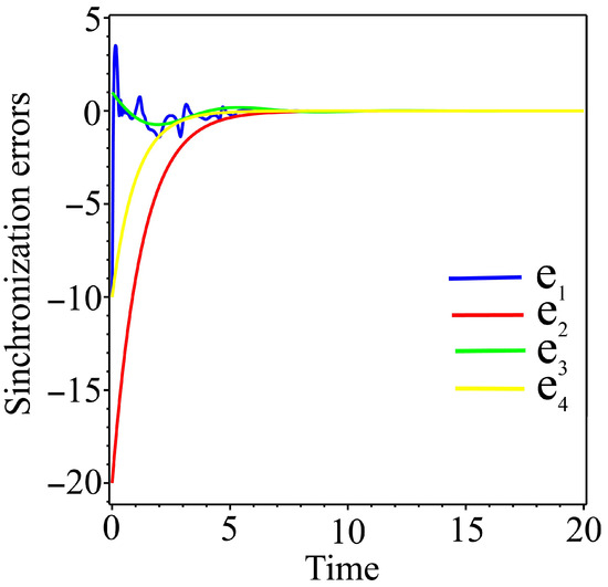
Figure 15.
Time-history of the synchronization errors.
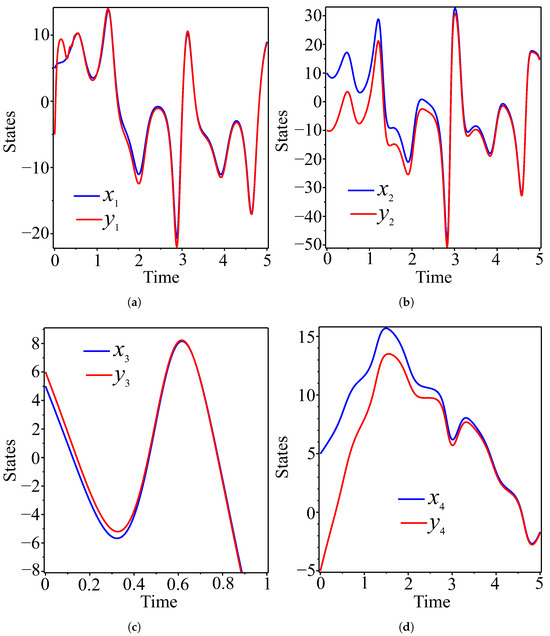
Figure 16.
Synchronized state variables of master (blue) and slave (red) systems. (a) ; (b) ; (c) ; (d) .
6. Adaptive Control Method for Chaotic Masking and Decoding Useful Signals
The hyperchaotic system (10) exhibits pronounced sensitivity to initial conditions (see Figure 6) and parameter variations, which makes it highly effective in masking chaotic signals. In this approach, the information signal is embedded in one of the state variables of the system, effectively concealing it within the chaotic dynamics. The receiver, lacking knowledge of the exact system parameters, employs adaptive synchronization to recover the system dynamics and extract the encrypted signal simultaneously.
We consider an adaptive control method for synchronizing two identical 4D hyperchaotic systems initialized with different initial conditions and uncertain or unknown system parameters. A sinusoidal signal is selected as the information signal, while the chaotic state variable serves as the carrier signal for the encryption of information. The encrypted signal is mathematically expressed as the superposition of the information and carrier signals: . Consequently, the transmission equations can be derived from (10) as follows:
In practice, the receiver observes only a highly fluctuating chaotically masked signal, from which it is impossible to extract without prior knowledge of the dynamics and parameters of the system. The chaotic nature of the carrier signal effectively conceals the information content, rendering conventional signal processing techniques ineffective.
Therefore, for successful signal decoding, the state variable in the receiver must be synchronized with the transmitter variable . Once synchronization is achieved, the information signal can be recovered as:
where represents the recovered information signal, is an encryption error. Consequently, the equations governing the receiving system are derived from (20) as
where . It is evident that as the error approaches zero, successful signal recovery becomes achievable. are rescaled adaptive control inputs (21) to be designed using estimates for unknown parameters , respectively.
To numerically verify secure communication, we utilized the nonlinear Equations (39) and (40) and applied the Runge–Kutta–Fehlberg (rkf45) method in the Maple computing environment. The initial conditions for the drive system (39) were set as follows:
and the response system was initialized with:
Figure 17 presents the simulation results for the secure communication scheme. The original information signal (Figure 17a) transforms into a chaotically masked state after encryption, as shown in Figure 17b, effectively concealing the content of the information and ensuring secure transmission. Following the decryption process, the information signal is successfully restored to its original form, as shown in Figure 17c. Figure 17d illustrates the waveform of the reconstruction error , which exhibits characteristics similar to the synchronization error observed in the adaptive control method discussed in the previous section (see Figure 16). In particular, the reconstruction error decreases exponentially and converges to zero after approximately s, indicating successful synchronization and signal recovery. The transient period corresponds to the time required for the adaptive controller to estimate the unknown system parameters and achieve synchronization between the transmitter and receiver dynamics.
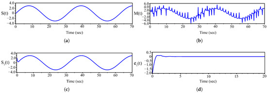
Figure 17.
(a) Information signal , (b) transmitted chaotic signal , (c) recovered signal , (d) error in the information signal .
These results demonstrate that the proposed adaptive control synchronization method effectively performs information encryption and decryption within acceptable error bounds, validating its potential for secure chaotic communication applications.
7. Application of Complete Synchronization of Hyperchaotic Systems to Detect Weak Signals
The application of chaotic synchronization methods for weak signal detection began with the foundational work of Pecora and Carroll [35], who demonstrated that specific subsystems of nonlinear chaotic systems can be synchronized by coupling them through standard signals [36]. Haykin and Li [37] advanced this field by presenting a novel method for detecting signals in ‘noise’, based on the assumption that the ‘noise’ is chaotic with at least one positive Lyapunov exponent, and employing neural networks for implementation [38]. Practical implementations were demonstrated in studies [39] using Chua’s circuit, where researchers developed a method to detect weak sinusoidal signals in intense noise using two synchronization systems to estimate different signal parameters [40]. An alternative approach [41] employing the Duffing oscillator revealed that this system exhibits high sensitivity to detect weak periodic signals while maintaining robustness against interference from signals at other carrier frequencies. In these seminal works [35,37,39,41], the theoretical and practical foundations for applying nonlinear dynamical systems to weak signal detection problems were established.
The weak signal detection mechanism is based on the fact that a weak external signal slightly disrupts the chaotic dynamics of the master system. While the slave system tries to synchronize with the master, this disturbance prevents perfect synchronization, resulting in a measurable synchronization error. By monitoring this error, in particular its amplitude and spectral characteristics, it becomes possible to detect and characterize the weak signal. We consider the detection of a weak periodic signal using two coupled hyperchaotic systems (10) in the master-slave configuration. The following set of nonlinear differential equations governs the master system:
where and define the amplitude and frequency of the weak periodic signal injected. The slave system receives the output of the master system through linear diffusive coupling:
where k is the coupling coefficient. The synchronization error remains small when , but increases significantly as soon as a weak signal is introduced. This property is exploited for signal detection, enabling the identification of low-amplitude signals through deviations from the synchronized regime.
7.1. Numerical Results
The system of master-slave differential Equations (43) and (44) was numerically integrated using the Runge–Kutta method with a fixed time step over the interval . Both systems are initialized with the same initial conditions:
The weak external signal applied to the master system was of the form:
Simulation results show that, in the absence of the signal , the slave system completely synchronizes with the master and all synchronization errors converge to zero, as shown in the upper part of Figure 18. However, with the weak signal active, a deviation from perfect synchronization becomes evident, as shown in the lower part of Figure 18. The presence of a weak signal results in an apparent deviation from complete synchronization, which facilitates its detection.
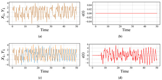
Figure 18.
Time evolution of the master variable (blue line) and the slave variable (yellow line), as well as synchronization errors . (a) the graphs when there is no signal ; (b) ; (c) the graphs for a weak input signal with , , and ; (d) synchronization error .
7.2. Filtering the Synchronization Error near Frequency
Figure 18 shows the evolution in time of the synchronization error . During an initial short time interval, complete synchronization is observed with , indicating that the slave system successfully tracks the master system. However, as time passes, chaotic desynchronization bursts appear, resulting in intermittent spikes in the error signal. To investigate whether a weak periodic signal is embedded in the error dynamics, numerical bandpass filtering was applied. The filtering results are presented in Figure 19. The error signal was filtered in a narrow frequency band centered on the known external frequency to isolate the corresponding harmonic component from the chaotic broadband background.
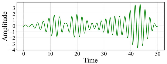
Figure 19.
Filtered component of the synchronization error near the frequency . The filtering reveals a quasi-sinusoidal signal, indicating the presence of the weak periodic forcing embedded in the chaotic dynamics.
Figure 20 shows the filtered synchronization error, where a quasi-sinusoidal component becomes visible.
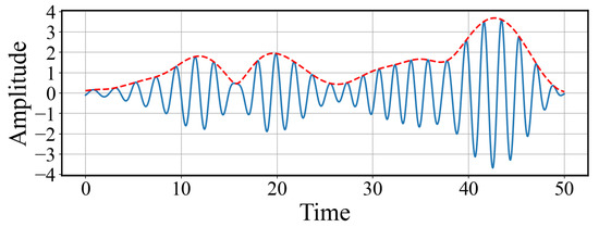
Figure 20.
Amplitude modulation of the filtered error signal. The red dashed line represents the envelope of the signal obtained using the Hilbert transform. The slowly varying amplitude indicates the influence of chaotic dynamics on the response to the weak periodic input.
To further analyze its temporal structure, the amplitude envelope was computed using the Hilbert transform, as shown in Figure 20. The red dashed curve represents the slowly varying envelope, which captures amplitude modulations induced by the chaotic background. This modulation illustrates how the weak periodic forcing interacts with the underlying chaotic dynamics, resulting in a non-uniform response.
This behavior is typical in synchronization-based signal detection and does not imply failure. In contrast, the emergence of a modulated sinusoidal component in the filtered error confirms the successful detection of the weak signal hidden within the chaotic system.
7.3. Spectral Detection of the Weak Signal
To assess the presence and extractability of the weak periodic signal, two spectral analyses were performed: one based on the raw synchronization error and the other on the bandpass-filtered version of this signal. Figure 21 presents the amplitude spectrum of the full error signal . The spectrum exhibits a broadband chaotic structure, characteristic of the underlying nonlinear dynamics. Despite this complexity, a distinct and narrow peak is observed at the driving frequency Hz, indicating that the weak periodic input leaves a detectable spectral trace even when embedded in chaotic fluctuations.
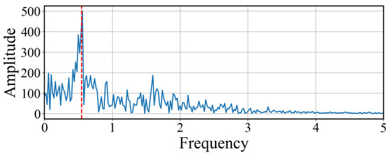
Figure 21.
Amplitude spectrum of the synchronization error signal . A sharp spectral peak appears at the expected frequency Hz (dashed red line), indicating the presence of the weak periodic signal against a broadband chaotic background.
In contrast, Figure 22 shows the spectrum of the error signal after narrowband filtering centered at . Here, the spectral energy is sharply concentrated in a narrow range around the expected frequency, while the chaotic background is strongly suppressed. This confirms that the weak periodic component has been effectively extracted from the broadband error dynamics.
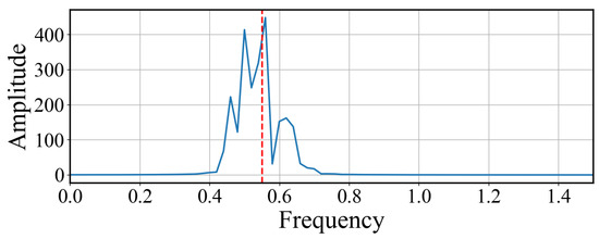
Figure 22.
Amplitude spectrum of the filtered synchronization error signal. The spectral energy is concentrated near the expected frequency Hz, indicating that the weak harmonic component has been successfully extracted from the chaotic background.
This comparison demonstrates the effectiveness of synchronization-based detection followed by frequency-selective filtering in identifying and isolating weak periodic signals buried in chaotic dynamics.
8. Practical Implementation of a 4D Memristor-Based Hyperchaotic System on Arduino UNO
This section demonstrates the practical feasibility of implementing a newly proposed four-dimensional memristive hyperchaotic system (10) on a widely available and inexpensive Arduino UNO microcontroller.
8.1. Chaotic Dynamic Based on Arduino-Generated Chaotic Sequences
To verify the feasibility of low-cost hardware for real-time nonlinear system simulation, system (10) was implemented on an Arduino UNO microcontroller using the explicit Euler method with time step and initial conditions (11). The experimental setup consisted of the Arduino Uno-based system connected to a computer, with the testing procedures documented in Figure 23.
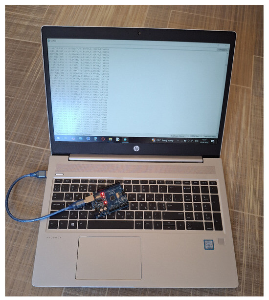
Figure 23.
Microcontroller-based experimental test platform.
The state variables were computed iteratively and transmitted data over UART (Universal Asynchronous Receiver/Transmitter) at 115,200 baud. Figure 24 presents a screenshot that shows the communication between the microcontroller and the computer.

Figure 24.
Screenshot of communication between the microcontroller and computer.
The resulting data stream was acquired and processed in MATLAB (R2017a), where phase portraits were reconstructed in projection planes , and , as shown in Figure 25.
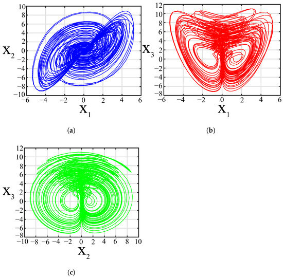
Figure 25.
Phase portraits of 4D memristor-based hyperchaotic system obtained from the microcontroller: (a) , (b) , (c) .
In particular, the trajectories obtained from the microcontroller closely matched those produced by symbolic-numerical integration in Mathematica (see Figure 5), as well as those generated in circuit-level simulation in Multisim (see Figure 12). This shows that even simple embedded systems can accurately capture and reproduce complex non-linear dynamics, enabling real-time analysis and validation of mathematical models through both software and hardware platforms.
8.2. Image Encryption and Decryption Using Arduino-Generated Chaotic Sequences
To demonstrate secure image processing using hardware-generated chaotic sequences, we developed a two-part implementation involving an Arduino UNO and MATLAB. The Arduino executes the numerical integration of the 4D chaotic system (10) using fourth-order functions.
The Runge–Kutta method (RK4) to generate a chaotic sequence in real time with initial conditions specified in (11). The chaotic data stream is transmitted via the serial port and is used in MATLAB to perform encryption and decryption of grayscale images. The encryption process includes two operations: a chaotic permutation of pixels and a bitwise XOR with the chaotic sequence. Decryption applies the inverse operations to recover the original image. The initial conditions for the system are set according to (11). The Arduino code (Algorithm 1) employs the Runge–Kutta 4th-order method for numerical integration, whereas the MATLAB code (Algorithm 2) performs image processing and visualization.
| Algorithm 1: Chaos generation on Arduino (see system (10), initial conditions (11)) |
Input: Initial state , step size h, iterations N Output: Chaotic bytes  |
| Algorithm 2: Image encryption and decryption in MATLAB |
Input: Grayscale image I, chaotic byte stream Output: Encrypted image E, decrypted image 1 Flatten I into vector 2 Receive chaotic sequence of same length 3 Generate permutation by sorting 4 Apply permutation: 5 Encrypt: 6 Decrypt: 7 Recover original order: 8 Reshape into image |
The simulation results using the grayscale images are shown in Figure 26. The perfect reconstruction quality is confirmed by the PSNR value of ∞ dB, indicating that there is no distortion between the original and decrypted images.

Figure 26.
Simulation results on Arduino UNO: chaotic sequence output and its application to image encryption and decryption. (a) original, encrypted, and decrypted image (photographer); (b) original, encrypted, and decrypted image (windmill).
9. Conclusions
In this paper, we introduced a novel four-dimensional memristor-based dynamical system by integrating an absolute memristor, as proposed by Bao [29], with the Munmuangsaen equations of five terms [13]. The proposed system satisfies the established criteria for generating hyperchaos: (a) it is dissipative, (b) it operates in a four-dimensional phase space, and (c) it incorporates three nonlinear terms. In particular, this hyperchaotic system comprises only seven terms and lacks equilibrium points, which may give rise to hidden attractors.
Characterized by two positive Lyapunov exponents, the system is classified as hyperchaotic, with a Kaplan–Yorke dimension () underscoring its high complexity. The bounded evolution of the Lyapunov function over extended simulations provides clear evidence of the dissipativity and global asymptotic stability of the constructed 4D hyperchaotic system. Numerical simulations reveal the phenomenon of multistability, resulting in the coexistence of hyperchaotic attractors under varying initial conditions. Furthermore, the system’s offset-boosting control behavior maintains constant Lyapunov exponent values, demonstrating that its hyperchaotic nature persists across different booster parameter settings.
The electronic circuit simulation of the proposed 4D system, implemented in Multisim 14, shows excellent agreement with the results obtained from Mathematica.
This study also presents new results for the application of the adaptive control method in synchronizing two identical 4D hyperchaotic systems with unknown parameters. The adaptive controllers were designed systematically using a feedback control strategy to ensure synchronization. The effectiveness of the proposed method was rigorously validated through Lyapunov stability theory. Numerical simulations demonstrated that all system state variables achieve synchronization, with synchronization errors converging to zero in a short time.
Using an adaptive control approach, a simple and effective scheme for chaotic masking and recovery of a harmonic signal was successfully demonstrated. The analysis confirms that complete synchronization of chaotic systems provides a practical approach for detecting weak periodic signals embedded in nonlinear dynamics. Injecting a weak signal into the master system disrupts synchronization, resulting in a measurable error in synchronization.
This sensitivity enables reliable identification of weak inputs, making the method suitable for a range of engineering applications, including sensor systems, covert communications, and signal monitoring in noisy environments.
The use of the Arduino UNO microcontroller demonstrates the practical feasibility of implementing real-time simulations of complex hyperchaotic systems on low-cost hardware. Moreover, its integration with MATLAB for image encryption and decryption confirms its potential in lightweight, hardware-based cryptographic applications.
Author Contributions
Conceptualization, M.I.K. and I.S.; methodology, M.I.K.; software, M.I.K.; validation, M.I.K. and I.S.; formal analysis, M.I.K.; investigation, M.I.K. and I.S.; resources, I.S.; data curation, M.I.K.; writing-original draft preparation, M.I.K. and I.S.; writing-review and editing, M.I.K. and I.S.; visualization, M.I.K. and I.S.; supervision, M.I.K. and I.S.; project administration, I.S. All authors have read and agreed to the published version of the manuscript.
Funding
This research received no external funding.
Data Availability Statement
The original contributions presented in this study are included in the article. Further inquiries can be directed to the corresponding author.
Acknowledgments
The authors gratefully acknowledge the anonymous reviewers for their valuable feedback, which helped improve the manuscript.
Conflicts of Interest
The authors declare no conflicts of interest.
References
- Hashemi, S.; Pourmina, M.A.; Mobayen, S.; Alagheband, M.R. Multiuser wireless speech encryption using synchronized chaotic systems. Int. J. Speech Technol. 2021, 24, 651–663. [Google Scholar] [CrossRef]
- Shahna, K.U. Novel chaos based cryptosystem using four-dimensional hyper chaotic map with efficient permutation and substitution techniques. Chaos Solitons Fractals 2023, 170, 113383. [Google Scholar] [CrossRef]
- Ponnambalam, M.; Ponnambalam, M.; Ghazalah, S.A.; Sambas, A. Hybrid inter woven scrambling with spiral shell 3D hyperchaotic diffusion for secure color image encryption. Nonlinear Dyn. 2025. [Google Scholar] [CrossRef]
- Ye, C.J.; Sharpe, Z.; Heng, H.H. Origins and consequences of chromosomal instability: From cellular adaptation to genome chaos-mediated system survival. Genes 2020, 11, 1162. [Google Scholar] [CrossRef] [PubMed]
- Lin, H.; Wang, C.; Cui, L.; Sun, Y.; Zhang, X.; Yao, W. Hyperchaotic memristive ring neural network and application in medical image encryption. Nonlinear Dyn. 2022, 110, 841–855. [Google Scholar] [CrossRef]
- Kozlovska, O.; Sadyrbaev, F.; Samuilik, I. A New 3D Chaotic Attractor in Gene Regulatory Network. Mathematics 2024, 12, 100. [Google Scholar] [CrossRef]
- Zhou, X.; Sun, K.; Wang, H.; Yao, Z. Coexisting hyperchaos and multistability in a discrete memristor-coupled bi-neuron model. Nonlinear Dyn. 2024, 112, 9547–9561. [Google Scholar] [CrossRef]
- Lorenz, E.N. Deterministic nonperiodic flow. J. Atmos. Sci. 1963, 20, 130–141. [Google Scholar] [CrossRef]
- Sprott, J.C. Simplest dissipative chaotic flow. Phys. Lett. 1997, 228, 271–274. [Google Scholar] [CrossRef]
- der Schrier, G.V.; Maas, L.R.M. The diffusionless Lorenz equations; Shil’nikov bifurcations and reduction to an explicit map. Phys. D Nonlinear Phenom. 2000, 141, 19–36. [Google Scholar] [CrossRef]
- Elwakil, A.S.; Ozoguz, S.; Kennedy, M.P. Creation of a complex butterfly attractor using a novel Lorenz-Type system. IEEE Trans. Circuits Syst. I Fundam. Theory Appl. 2002, 49, 527–530. [Google Scholar] [CrossRef]
- Toncharoen, C.; Srisuchinwong, B. A heart-sound-like chaotic attractor and its synchronization. In Proceedings of the 6th International Conference on Telecommunications and Information Technology (ECTI-CON 2009), Chonburi, Thailand, 6–9 May 2009; Volume 1, pp. 407–410. [Google Scholar] [CrossRef]
- Munmuangsaen, B.; Srisuchinwong, B. A new five-term simple chaotic attractor. Phys. D Phys. Lett. 2009, 373, 4038–4043. [Google Scholar] [CrossRef]
- Chang, P.H.; Kim, D. Introduction and synchronization of a five-term chaotic system with an absolute-value term. Nonlinear Dyn. 2013, 73, 311–323. [Google Scholar] [CrossRef]
- Tamba, V.K.; Pham, V.T.; Hoang, D.V.; Jafari, S.; Alsaadi, F.E.; Alsaadi, F.E. Dynamic system with no equilibrium and its chaos anti-synchronization. Automatika 2018, 59, 35–42. [Google Scholar] [CrossRef]
- Gokyildirim, A.; Kocamaz, U.E.; Uyaroglu, Y.; Calgan, H. A novel five-term 3D chaotic system with cubic nonlinearity and its microcontroller-based secure communication implementation. Int. J. Electron. Commun. 2023, 160, 154497. [Google Scholar] [CrossRef]
- Sprott, J.C. Elegant Automation; World Scientific: Singapore, 2023; 348p. [Google Scholar] [CrossRef]
- Chua, L.O. Memristor-the missing circuit element. IEEE Trans. Circuit Theory 1971, 18, 507–519. [Google Scholar] [CrossRef]
- Radwan, A.G.; Fouda, M.E. On the Mathematical Modeling of Memristor, Memcapacitor, and Meminductor; Springer: Cham, Switzerland, 2015. [Google Scholar] [CrossRef]
- Pham, V.T.; Volos, C.; Gambuzza, L.V. A memristive hyperchaotic system without equilibrium. Sci. World J. 2014, 2014, 368986. [Google Scholar] [CrossRef]
- Rajagopal, K.; Bayani, A.; Khalaf, A.J.M.; Namazi, H.; Jafari, S.; Pham, V.T. A no-equilibrium memristive system with four-wing hyperchaotic attractor. Int. J. Electron. Commun. (AEU) 2018, 95, 207–215. [Google Scholar] [CrossRef]
- Singh, P.P.; Roy, B.K.; Volos, C. Chapter 9—Memristor-based novel 4D chaotic system without equilibria. In Advances in Nonlinear Dynamics and Chaos (ANDC), Mem-Elements for Neuromorphic Circuits with Artificial Intelligence Applications; Volos, C., Pham, V.-T., Eds.; Academic Press: Cambridge, MA, USA, 2021; pp. 183–205. [Google Scholar] [CrossRef]
- Tamba, V.K.; Tagne, F.K.; Biamou, A.L.M.; Nkeing, M.C.; Takougang, A.N. Chapter 7—Hidden extreme multistability generated from a novel memristive two-scroll chaotic system. In Advances in Nonlinear Dynamics and Chaos (ANDC), Mem-Elements for Neuromorphic Circuits with Artificial Intelligence Applications; Volos, C., Pham, V.-T., Eds.; Academic Press: Cambridge, MA, USA, 2021; pp. 147–164. [Google Scholar] [CrossRef]
- Irfan, A. Simple Chaotic Jerk, Hyperjerk, and Hyperchaotic Hyperjerk Circuits and Systems: Families of Self-Excited and Hidden Attractors. Ph.D. Thesis, Thammasat University, Bangkok, Thailand, 2020. [Google Scholar]
- Zhang, H.; Zhang, W.; Zhao, Y.; Ji, M. Adaptive state observers for incrementally quadratic nonlinear systems with application to chaos synchronization. Circuits Syst. Signal Process. 2020, 39, 1290–1306. [Google Scholar] [CrossRef]
- Tohidi, S.; Yildiz, Y.; Kolmanovsky, I. Adaptive control allocation for constrained systems. Automatica 2020, 121, 109161. [Google Scholar] [CrossRef]
- Vaidyanathan, S.; Volos, C.K.; Pham, V.T. Hyperchaos, adaptive control and synchronization of a novel 5-D hyperchaotic system with three positive Lyapunov exponents and its SPICE implementation. Arch. Control Sci. 2014, 24, 409–446. [Google Scholar]
- Vaidyanathan, S.; Volos, C.K. Analysis and adaptive control of a novel 3-D conservative no-equilibrium chaotic system. Arch. Control Sci. 2015, 25, 333–353. [Google Scholar] [CrossRef]
- Liu, X.; Zhang, X.Y.; Li, P.; Yan, H. A new Lorentz chaotic system and its circuit implementation. In Proceedings of the 8th EAI International Conference on Green Energy and Networking, GreeNets 2021, Dalian, China, 6–7 June 2021. [Google Scholar]
- Silva, C.P. Shil’nikov’s theorem—A tutorial. IEEE Trans. Circuits Syst. 1993, 40, 675–682. [Google Scholar] [CrossRef]
- Pareschi, J.F.; Rovatti, R.; Setti, G. On statistical tests for randomness included in the NIST SP800-22 test suite and based on the binomial distribution. IEEE Trans. Inf. Forensics Secur. 2012, 7, 491–505. [Google Scholar] [CrossRef]
- Wen, J.; Feng, Y.; Tao, X.; Cao, Y. Dynamical Analysis of a New Chaotic System: Hidden Attractor, Coexisting-Attractors, Offset Boosting, and DSP Realization. IEEE Access 2021, 9, 167920–167927. [Google Scholar] [CrossRef]
- Sedra, A.S.; Smith, K.C. Microelectronics Circuits, 4th ed.; Oxford University Press: New York, NY, USA, 1998. [Google Scholar]
- Khalil, H.K. Nonlinear System; Prentice Hall: Upper Saddle River, NJ, USA, 2002. [Google Scholar]
- Pecora, L.M.; Carroll, T.L. Synchronization in chaotic systems. Phys. Rev. Lett. 1990, 64, 821–824. [Google Scholar] [CrossRef]
- Li, G.; Zhang, B. A Novel Weak Signal Detection Method via Chaotic Synchronization Using Chua’s Circuit. IEEE Trans. Ind. Electron. 2017, 64, 2255–2265. [Google Scholar] [CrossRef]
- Haykin, S.; Li, X.B. Detection of signals in chaos. Proc. IEEE 1995, 83, 95–122. [Google Scholar] [CrossRef]
- Dwivedi, A.; Mittal, A.K.; Dwivedi, S. Chaotic communication using Pecora Carroll complete replacement and parameter modulation without controller. In Proceedings of the 2014 Students Conference on Engineering and Systems, Allahabad, India, 28–30 May 2014; pp. 1–4. [Google Scholar] [CrossRef]
- Wang, G.; Chen, D.; Lin, J.; Chen, X. The application of chaotic oscillators to weak signal detection. IEEE Trans. Ind. Electron. 1999, 46, 440–444. [Google Scholar] [CrossRef]
- Pecora, L.M.; Carroll, T.L.; Johnson, G.A.; Mar, D.J.; Heagy, J.F. Fundamentals of synchronization in chaotic systems, concepts, and applications. Chaos 1997, 7, 520–543. [Google Scholar] [CrossRef]
- Li, Y.; Yang, B.J. Chaotic system for the detection of periodic signals under the background of strong noise. Chin. Sci. Bull. 2003, 48, 508–510. [Google Scholar] [CrossRef]
Disclaimer/Publisher’s Note: The statements, opinions and data contained in all publications are solely those of the individual author(s) and contributor(s) and not of MDPI and/or the editor(s). MDPI and/or the editor(s) disclaim responsibility for any injury to people or property resulting from any ideas, methods, instructions or products referred to in the content. |
© 2025 by the authors. Licensee MDPI, Basel, Switzerland. This article is an open access article distributed under the terms and conditions of the Creative Commons Attribution (CC BY) license (https://creativecommons.org/licenses/by/4.0/).