Article

Very Large Angular Oscillations (Up to 3π/4) of the Physical Pendulum—A Simple Trigonometric Analytical Solution

by
Joao C. Fernandes
Physics Department, Instituto Superior Técnico, Av. Rovisco Pais, 1049-001 Lisboa, Portugal
Mathematics 2025, 13(17), 2836; https://doi.org/10.3390/math13172836
Submission received: 1 August 2025 / Revised: 26 August 2025 / Accepted: 30 August 2025 / Published: 3 September 2025

Abstract

The oscillatory properties of pendular motion, along with the associated energetic conditions, are used to induce analytical functions capable of simultaneously describing the angular position and velocity. To describe the angular position of a generic pendulum, for very large amplitudes of oscillation, we used the numerical solutions obtained from the numerical resolution of the differential equation of motion. The solver software needed was built using the LabView 2019 platform, but any other ODE solver containing peak and valley detectors can be used. The fitting software and plots were performed with the ORIGIN 7.0 program, but also other equivalent programs can be used. For a non-damped pendulum, an analytical model is proposed, built from simple trigonometric functions, but containing the important physical information of the dependence between the period and amplitude of oscillation. The application of the proposed model, using the numerical solutions of the non-approximated differential equation of motion, shows very good agreement, less than 0.01%, for large amplitudes, up to 3π/4.

1. Introduction

When pendula motion is studied in university graduate courses large angle oscillations are usually omitted.
Two reasons contribute to that omission; the period is amplitude-dependent and there is a lack of simple periodic functions able to reproduce correctly the angular dislocation.
The period amplitude dependence problem can be removed because there is an analytical solution, a function involving the first kind complete elliptical integral that is well known by academics, with calculation nowadays simplified as it is included in several mathematical software packages used widely.
The second problem, a periodic function to describe θ t is more paradigmatic because the usual function cos ω t is inaccurate for large angle oscillations, even when the frequency amplitude dependence ω θ 0 is correctly introduced (Figure 1, Figure 2 and Figure 3).
For these reasons, most of the referenced authors, and we cite several [1,2,3,4,5,6,7,8,9,10,11,12,13], seek analytical solutions in the form of a sum of sinusoidal functions, truncating this sum when the error is acceptable.
What we propose in this article is different, a simple trigonometric analytical solution, of the type sin δ cos ω t sin δ for the angular deviation of a pendulum without damping, up to an initial angle of 135°.
We also showed that its derivative, the angular velocity, also satisfies the data obtained in the numerical solution of the oscillation ODE.
The letters introduced follow the usual nomenclature: θ t stands for angle deviation, θ 0 is the initial angle, and ω = 2 π T is the angular frequency (T is period, time between three consecutive zeros of the speed). It is assumed in all examples that the pendulum is released at the initial time t = 0 from angle θ 0 .
The results presented are valid for any physical pendulum of mass m, inertia moment I, and distance L from pivot to the center of mass. The natural frequency is therefore ω 0 2 = m g L I .
In the following section, we will focus our attention on the frictionless pendulum.
The traditional Model 1 is presented, which, as we already know, does not provide an adequate response, either for the amplitude or for the velocity, for large initial angles.
We then develop our proposed Model 2, which, as will be shown in Figure 1, Figure 2, Figure 3, Figure 4, Figure 5 and Figure 6, describes amplitude and velocity along the entire path with great accuracy. This section may be useful in teaching pendulum motion at engineering universities, without worrying about friction forces.
In Section 3, we will address the pendulum with friction, the damped pendulum. The introduction of friction forces in our pendulum requires special care with the solution of the new ODE. For this reason, we consider that Section 3 can be considered as an extra of the Appendix type. As such, it may only be of interest to those who wish to study pendulum situations with various friction forces.
In this article, we will introduce three types of frictional forces: constant, proportional to velocity, and proportional to the square of velocity. In a recent article [14], the author addresses this theme without concern for describing large initial angles.

2. The Undamped Pendulum

2.1. Differential Equations and Period

The fundamental equations governing motion and energy of a generic undamped physical pendulum are simpler to write:
I d 2 θ d t 2 = m g L sin θ d 2 θ d t 2 = ω 0 2 sin θ
1 2 I d θ d t 2 m g L cos θ = m g L d θ d t 2 = 2 ω 0 2 cos θ cos θ 0
The extrema of θ t are the nulls of velocity: d θ d t = 0 θ e x t r e m a = ± θ 0 .
The extrema of velocity are nulls of acceleration:
sin θ = 0 d θ d t e x t r e m a = 2 ω 0 sin θ 0 2
Notice that Equation (2) can be easily obtained by multiplying Equation (1) by d θ and integrating once.
To obtain information about the period, it is necessary to solve Equation (2) to time.
Assuming that the pendulum falls from the maximum angle,
d t = d θ ω 0 2 cos θ cos θ 0 t = θ 0 θ d θ ω 0 2 cos θ cos θ 0
Using transformation to the semi angles, Equation (4) writes
t = θ 0 θ d θ 2 ω 0 sin 2 θ 0 2 sin 2 θ 2
This integral can be again transformed, using sin θ 2 = sin θ 0 2 sin φ . Note that when θ is maximum φ = π 2 and when θ is minimum φ = π 2 . When θ is null φ = 0 . When it starts from the maximum,
t = π 2 φ d φ ω 0 1 sin 2 θ 0 2 sin 2 φ
The quarter period is reached when θ = 0 , that is φ = 0 ,
T 4 = 1 ω 0 0 π 2 d φ 1 sin 2 θ 0 2 sin 2 φ
This integral is the complete first order elliptic integral K sin 2 θ 0 2 ; π 2 , tabulated and found in mathematical packages as a predefined function. The expression for the period is
T = 4 ω 0 K sin 2 θ 0 2 ; π 2 = T 0 2 π K sin 2 θ 0 2
The ratio between frequencies will be widely used and is designated by ε θ 0 ,
ε θ 0 = ω ω 0 = T 0 T = π 2 K sin 2 θ 0 2

2.2. Solutions for Angle and Velocity

2.2.1. Model 1

Knowing the period we concentrate our attention into the periodic analytical function able to reproduce the angular dislocation. The simpler choice is the usual trigonometric cos ω t , that is, the exact solution for the common harmonic oscillator:
θ t = θ 0 cos ω θ 0 t d θ d t = ω θ 0 sin ω θ 0 t
This choice seems to be not accurate for large initial angles.
The comparison with the numerical results obtained from the solution of differential Equation (1), (Figure 1, Figure 2 and Figure 3), presents significant differences for large angles.
However, the worst problem comes from the velocity Equation (9), (Figure 4, Figure 5 and Figure 6).
This sinusoidal function predicts a maximum velocity d θ d t max = ω θ 0 and we know that maximum velocity should be, by expression (3), d θ d t max = 2 ω 0 sin θ 0 2 .
Equating the two, a condition is obtained: ω ω 0 = sin θ 0 2 θ 0 2 .
This ratio was calculated in the last section for a period and depends on the elliptical integral
ε θ 0 = ω ω 0 = π 2 K sin 2 θ 0 2 .
The two results are incompatible.
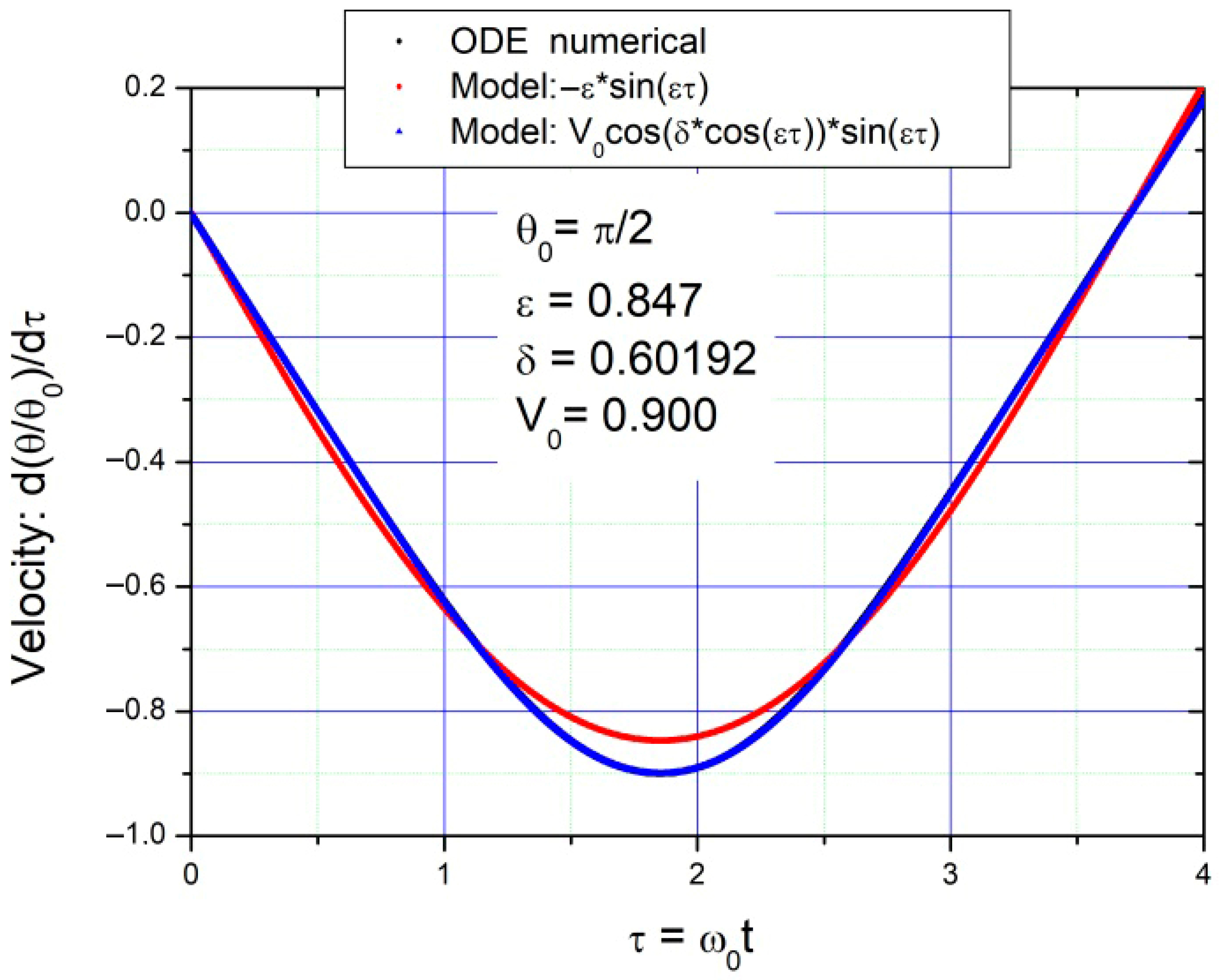
As an example, for θ 0 = π 2 sin θ 0 2 θ 0 2 = 0.9003 and ω ω 0 = ε θ 0 = 0.847 , the difference is obvious.

2.2.2. Model 2

We need a different function, whose derivative should lead to the right velocity amplitude:
θ t = θ 0 f u   with   u = cos ω t d θ d t = θ 0 ω d f d u sin ω t
with the conditions
f ± 1 = ± 1
and
d f d u u = 0 = ω 0 ω sin θ 0 2 θ 0 2
A good candidate is
f u = sin δ cos ω t sin δ = sin δ u sin δ
A parameter δ was introduced. This function always satisfies condition (11) for every δ.
Its derivative is as follows:
d f d u = δ cos δ u sin δ
To satisfy condition (12), Equation (14) imposes a definition of parameter δ:
d f d u u = 0 = δ sin δ = ω 0 ω sin θ 0 2 θ 0 2 = 1 ε sin θ 0 2 θ 0 2
Parameter δ θ 0 can be extracted from the knowledge of θ 0 and ε θ 0 ;
sin δ δ sin θ 0 2 θ 0 2 = π 2 K θ 0
The transcendent Equation (16) can be solved numerically, using for instance the Newton–Raphson method, to extract the solution δ θ 0 .
Now we have system (10) completely defined:
θ t = θ 0 sin δ cos ε ω 0 t sin δ d θ d t = 2 ω 0 sin θ 0 / 2 cos δ cos ε ω 0 t sin ε ω 0 t
The pendulum physical characteristics appear in these equations only in parameter ω 0 .
To obtain a system independent of these characteristics, it is enough to change from variable t to variable τ ( τ = ω 0 t ). Furthermore, to compare the different examples in this study, we used relative angular dislocation θ / θ 0 , instead of the absolute value. The system used, named Model 2, was
θ τ θ 0 = sin δ cos ε τ sin δ d θ / θ 0 d τ = sin θ 0 / 2 θ 0 / 2 cos δ cos ε τ sin ε τ
Parameter ε θ 0 is given by expression (8) and δ θ 0 is the solution of Equation (16).
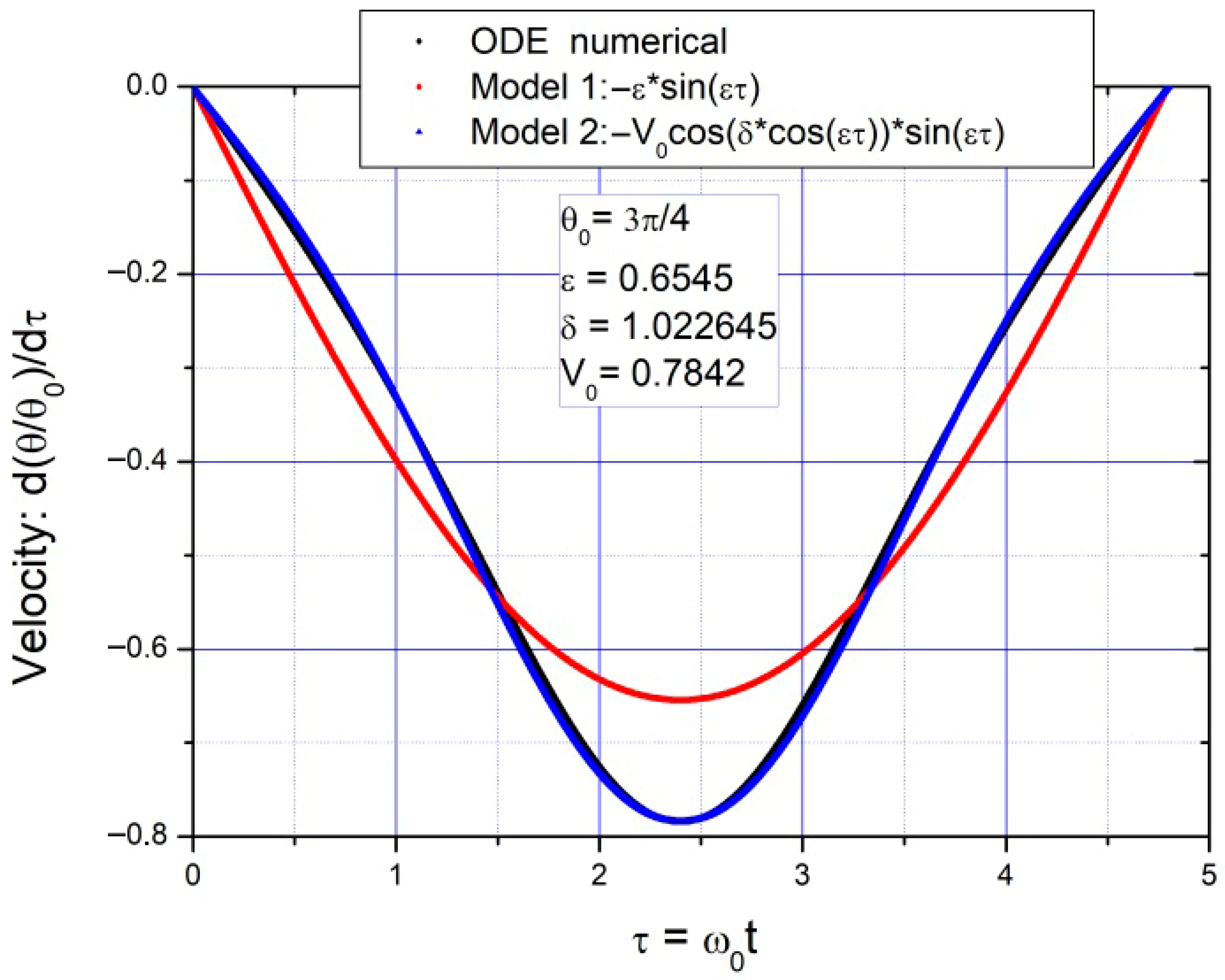
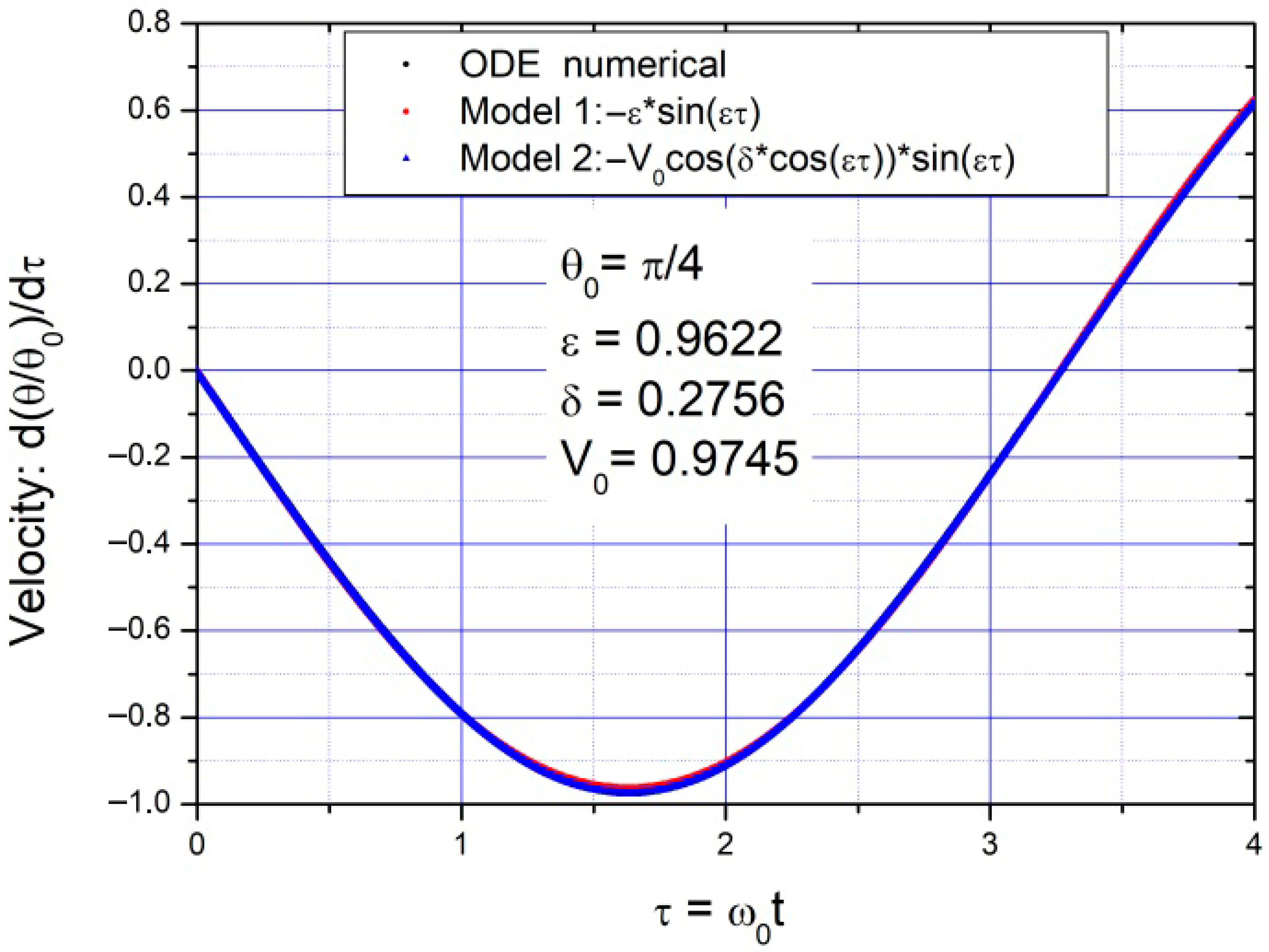
We chose three standard initial angles 3 π 4 ; π 2 ; π 4 to compare the results obtained by the numerical solution of the motion differential Equation (1), with Model 1 (system 9) and Model 2 (system 18).
In Figure 1, Figure 2 and Figure 3, the results for the three angles are presented and in Figure 4, Figure 5 and Figure 6 the respective velocities are presented.
The simpler Model 1 is not appropriate, but Model 2 adjusts very well the numeric data.
The simpler Model 1 begins to show a disagreement with the numerical solution, especially halfway, because the predicted minima differ from the numerical ODE solution. Model 2 adjusts very well all the way.
Both models describe well the evolution of the velocity during the initial half period, although Model 2 shows a better agreement.

2.3. Conclusions for the Undamped Pendulum

This work shows that the large angle oscillations of an undamped pendulum can be suitably characterized using a simple and univocal composed sinusoidal function. The introduction of an amplitude dependent parameter allows the correct angular description. The correct angular velocity is obtained by simple differentiation of the angular function.
We can conclude that, up to 130°, Model 2 is always much superior to the traditional model.
The exploration for higher angles begins to show divergences, and we would have to develop more complex analytical functions that are not the more didactic objective of this article.

3. The Damped Pendulum

Let us accept that the main forces of friction acting on our pendulum can be of three types: constant, proportional to velocity, and proportional to the square of velocity.
In a recent article [14], the author explains these three types of friction acting in pendular motion and modulating its extremes. The constant is of the Coulomb type, the one proportional to velocity is the traditional viscous, and the one proportional to the square of velocity is related to high speeds.
One of the fundamental reasons why Model 2 succeeds where Model 1 does not function is that the average value of the quantities, especially the velocity, is different in the two cases.
Now, with the different types of friction forces depending on speed, we will need to calculate these average values.
For this reason, we anticipate the calculation of these average values right away. We will see that the results will be important later for Equation (28).
The Expressions (19), (21), and (22) represent, respectively, the average values of speed, the square of speed, and the cube of speed for the pendulum:
θ ˙ ¯ = ω 0 θ 0 K θ 0                                           θ ˙ 2 ¯ = θ ˙ max 2 1 1 E θ 0 K θ 0 sin 2 θ 0 2                                           θ ˙ 3 ¯ = 2 ω 0 3 K θ 0 sin θ 0 θ 0 cos θ 0
Using the new differential equation of motion (23), we were able to derive differential Equation (30) for the angular amplitude. To obtain analytical solutions, it is preferable to transform it into a velocity, Equation (31).
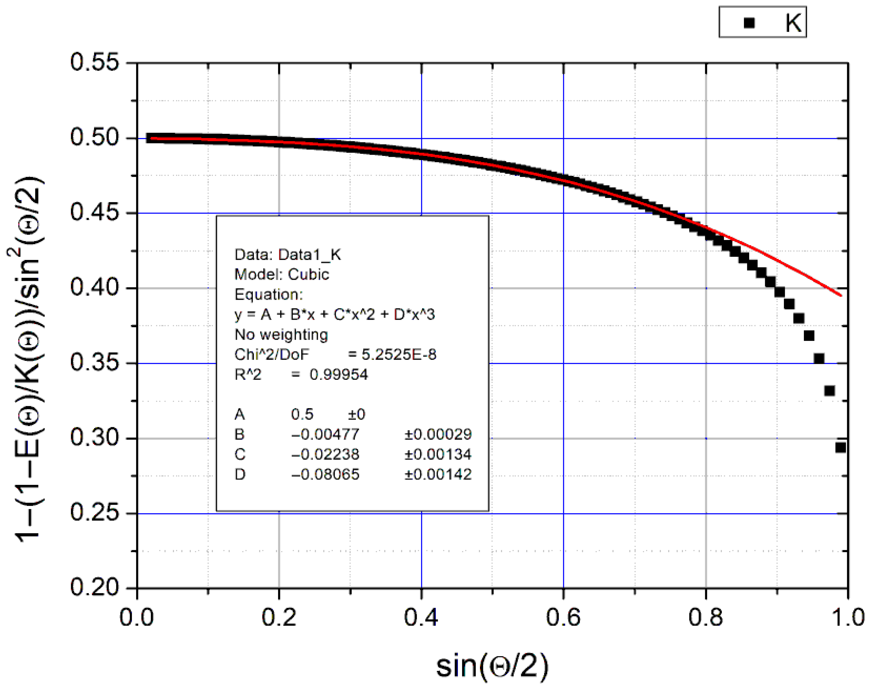
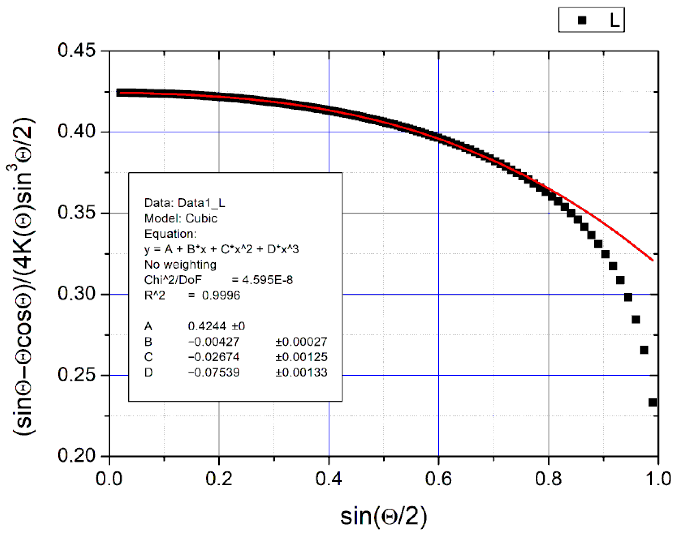
We found that there are three functions f μ , f λ , and f β that completely affect and dominate each of the friction coefficients. These three functions are calculated in Figure 7, Figure 8 and Figure 9, adjusting to the numerical data. It was found that, for angles up to 90°, each of the functions can be defined by a third-degree polynomial, thus obtaining a matrix (34).
Substituting into the initial Equation (31) we obtain an ODE (35) for the speed, linear of the 5th degree.
To achieve some practical results, we assume that the terms of the speed with a degree higher than quadratic can be neglected, and we obtain a much-simplified ODE (36), where there are only three constant coefficients: a, b, and c, which depend only on the friction coefficients expression (37).
In Section 4, we will verify Equation (36) with the numerical data from the solution of the equation using LabView software [15,16]. Three practical examples of different forces were made.
In the first case, the pendulum only contains the force of viscous friction and two different friction coefficients, λ = 0.008 in Figure 10 and λ = 0.08 in Figure 11.
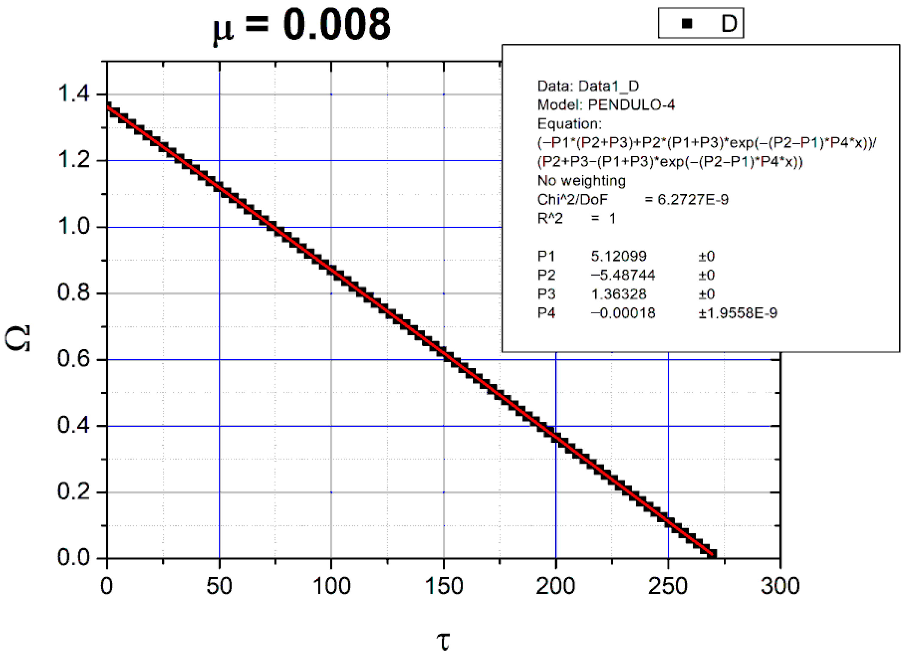
In the second example, the pendulum contains only the constant friction force and two different coefficients of friction, μ = 0.002 in Figure 12 and μ = 0.008 in Figure 13.
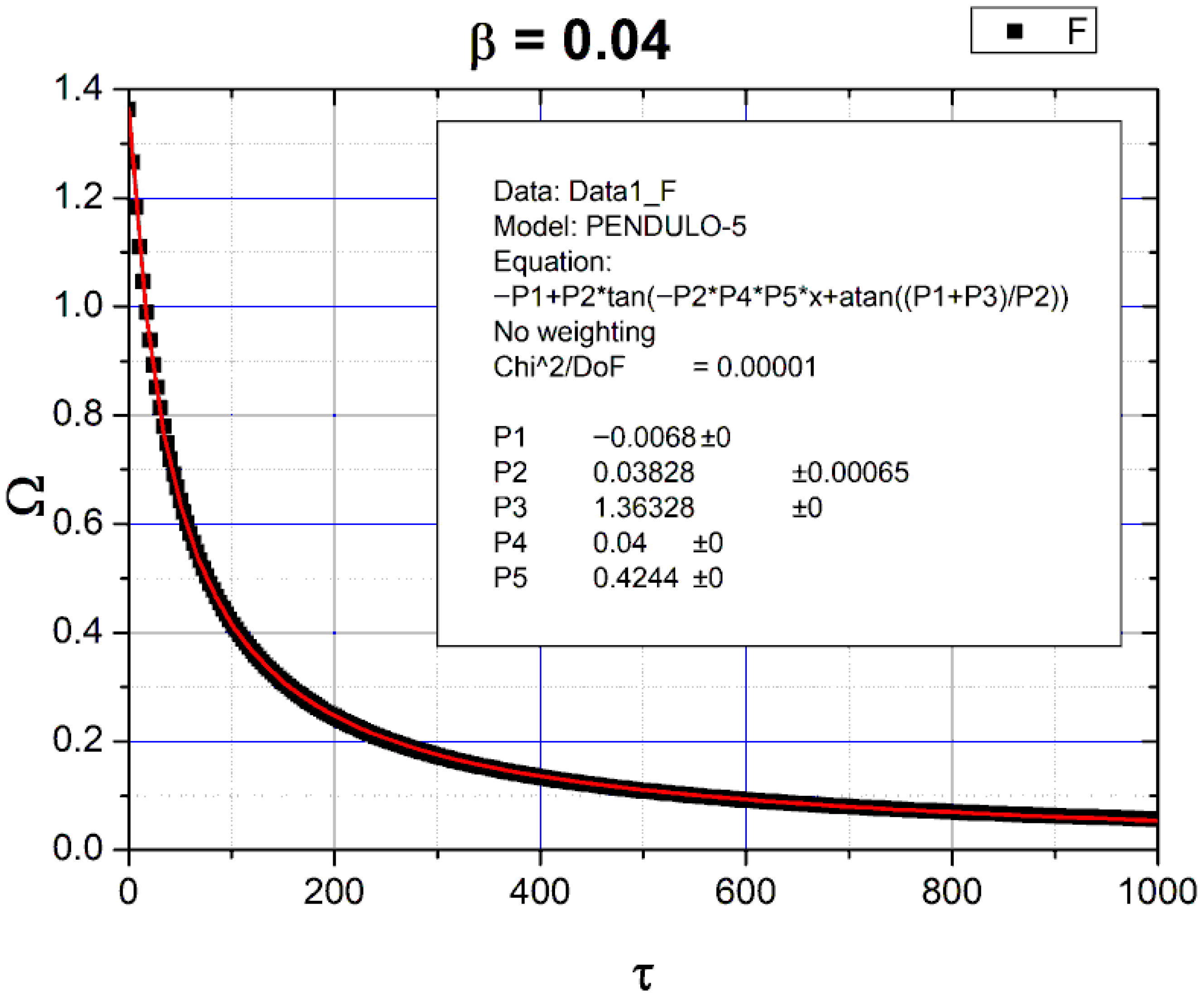
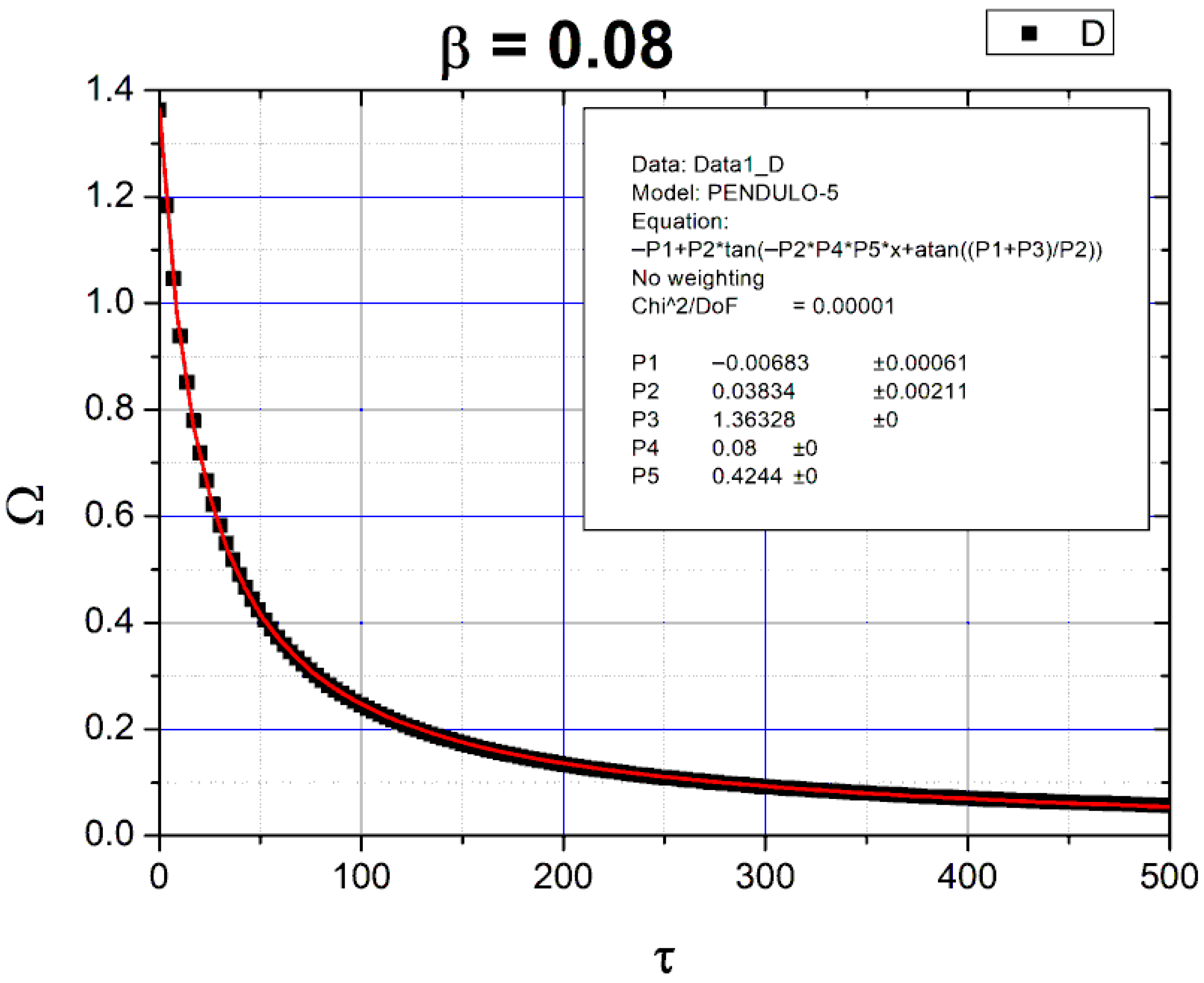
In the third example, the pendulum contains only the force of quadratic turbulent friction and three different friction coefficients; b = 0.04 in Figure 14, b = 0.08 in Figure 15, and b = 0.008 in Figure 16.

3.1. Average Values of Velocity

3.1.1. Half Period Velocity Average Value θ ˙ ¯

There are some important physical consequences of the period amplitude dependence found in (7). The average value of velocity in each half cycle depends not only on the extrema angle but also on the half period.
The harmonic oscillator has an average velocity 4 θ 0 T 0 = 2 ω 0 θ 0 π and the value for the pendulum is
θ ˙ ¯ = 4 θ 0 T 0 π 2 K θ 0 = ω 0 θ 0 K θ 0
Only for small values of amplitude they are similar. For instance, if
θ 0 = π 2 K sin 2 π 4 = 1.85407 ,
meaning that the pendulum average velocity is 15.3% lower than a linear oscillator.

3.1.2. Half Period Square Velocity Average Value θ ˙ ¯ 2

The square velocity given by (2) changes signal each half cycle;
d θ d t = ± 2 ω 0 sin 2 θ 2 sin 2 θ 0 2
To obtain the average value we integrate over half a period:
θ ˙ 2 ¯ = 0 T 2 d θ d t 2 d t T 2 = θ 0 θ 0 d θ d t d θ T 0 K θ 0 π = ω 0 2 K θ 0 θ 0 θ 0 sin 2 θ 2 sin 2 θ 0 2 d θ
Using, as before, sin θ 2 = sin θ 0 2 sin φ , we obtain
θ ˙ 2 ¯ = 4 ω 0 2 K θ 0 sin 2 θ 0 2 0 π 2 cos 2 φ 1 sin 2 θ 0 2 sin 2 φ d φ = 4 ω 0 2 K θ 0 0 π 2 cos 2 θ 0 2 1 sin 2 θ 0 2 sin 2 φ + 1 sin 2 θ 0 2 sin 2 φ d φ
The first integral gives the elliptic integral of first kind K sin 2 θ 0 2 and the second the elliptic integral of second kind E sin 2 θ 0 2 .
θ ˙ 2 ¯ = 4 ω 0 2 K θ 0 cos 2 θ 0 2 K θ 0 + E θ 0 = 4 ω 0 2 sin 2 θ 0 2 1 + E θ 0 K θ 0
Using the maximum velocity, the expression is
θ ˙ 2 ¯ = 4 ω 0 2 sin 2 θ 0 2 1 1 E θ 0 K θ 0 sin 2 θ 0 2 = θ ˙ max 2 1 1 E θ 0 K θ 0 sin 2 θ 0 2
The corrective term inside parentheses is a characteristic of pendulum motion.
For small amplitudes, the ratio of the two elliptic integrals is E θ 0 K θ 0 1 1 2 sin 2 θ 0 2 and this term is close to ½ the average value of the quadratic sinusoidal functions, characteristic of a linear oscillator.
In fact, for a linear oscillator, the calculation is simple:
θ ˙ 2 ¯ = 0 T 2 d θ d t 2 d t T 0 2 = θ 0 θ 0 d θ d t d θ T 0 2 = 2 ω 0 T 0 θ 0 θ 0 θ 0 2 θ 2 d θ = ω 0 2 θ 0 2 2

3.1.3. Half Period Cubic Velocity Average Value θ ˙ ¯ 3

To obtain the average value we integrate over half a period;
θ ˙ 3 ¯ = 0 T 2 d θ d t 3 d t T 2 = θ 0 θ 0 d θ d t 2 d θ T 0 K θ 0 π = ω 0 3 K θ 0 θ 0 θ 0 cos θ 0 + cos θ d θ
This is a direct integration:
θ ˙ 3 ¯ = 2 ω 0 3 K θ 0 sin θ 0 θ 0 cos θ 0
For small angles, sin θ 0 θ 0 θ 0 3 6 , cos θ 0 1 θ 0 2 2 and K ( θ 0 ) π 2 . The average value rests θ ˙ 3 ¯ 4 ω 0 3 θ 0 3 3 π = 4 3 π θ ˙ max 3 .
For a linear oscillator the calculation is
θ ˙ 3 ¯ = 0 T 2 d θ d t 3 d t T 0 2 = θ 0 θ 0 d θ d t 2 d θ T 0 2 = 2 ω 0 2 T 0 θ 0 θ 0 θ 0 2 θ 2 d θ = 4 ω 0 3 θ 0 3 3 π

3.2. Differential Equations and Amplitude

Fundamental equation governing motion of a generic damped physical pendulum is, instead of (1),
I d 2 θ d t 2 = m g L sin θ μ R L θ ˙ θ ˙ λ R L θ ˙ β R L θ ˙ θ ˙
Three types of generic torques are included. A constant torque associated to pivot rotation, a viscous torque due to solid fluid flow, and a quadratic term usually associated with turbulent flow. The coefficients used have index R because they are real force coefficients: [ μ R N λ R k g / s β R k g / m ] .
Dividing by inertia (I) we obtain the equation for acceleration:
d 2 θ d t 2 = ω 0 2 sin θ μ A θ ˙ θ ˙ λ A θ ˙ β A θ ˙ θ ˙   with   μ A = μ R L I λ A = λ R L I β A = β R L I
The coefficients used now have index A because they are acceleration coefficients.
This equation can be made independent of the proper frequency by changing time to phase time τ = ω 0 t :
d 2 θ d τ 2 = sin θ μ θ ˙ θ ˙ λ θ ˙ β θ ˙ θ ˙   with   [ μ = μ R m g λ = λ R m g ω 0 β = β R m g ω 0 2 ]
Now all differentiation is for τ and the coefficients have lost the index.
This is the equation that must be solved to obtain the angle deviation and the angular velocity.
To obtain the energy equation we multiply Equation (23) by d θ d t :
d d t 1 2 I d θ d t 2 + d d t 2 m g L sin 2 θ 2 = μ R + λ R d θ d t + β R d θ d t 2 L d θ d t
The left side represents the instant power and the right side contains the instant dissipated power.
As before, this equation can be made independent of the proper frequency by changing time to phase time τ = ω 0 t :
d d τ θ ˙ 2 + 4 sin 2 θ 2 = 2 μ θ ˙ + λ θ ˙ 2 + β R θ ˙ 3
This is the energy ODE equation that will be used simultaneously with Equation (24) to obtain angle, angular velocity, and total energy.
To obtain information about the amplitude function, it is important to follow the instants of null velocity from Equation (25). We will follow these points ( τ i θ e x t r e m a ) θ ˙ = 0 by using the amplitude function Θ τ i = θ e x t r e m a τ i θ ˙ = 0 . This function is the tail of the angular amplitude.
From energy in Equation (25) we obtain important information; the velocity amplitude and the angular amplitude are related through a simple function θ ˙ e x t r e m a = 2 sin Θ 2 .
Of course they do not occur at the same instant, but the continuous angular amplitude function Θ τ enables us to obtain the continuous velocity amplitude function Ω τ = 2 sin Θ τ 2 .
The total energy variation in each half period can be evaluated by integrating (25) between two successive instants of null velocity:
Δ 4 sin 2 Θ 2 = 2 τ i τ i + 1 μ θ ˙ + λ θ ˙ 2 + β R θ ˙ 3 d τ
The time interval is Δ τ = τ i + 1 τ i = ω 0 T Θ 2 = π T Θ T 0 .
This ratio was evaluated in (8) and allows a univocal expression for the time interval:
Δ τ = 2 K sin 2 Θ 2
The average power loss in each half cycle is therefore the ratio of (26) and (27):
Δ 4 sin 2 Θ 2 Δ τ = 2 τ i τ i + 1 μ θ ˙ + λ θ ˙ 2 + β θ ˙ 3 d τ Δ τ = 2 μ θ ˙ ¯ + λ θ ˙ 2 ¯ + β θ ˙ 3 ¯
The result shows that the average power loss in each half cycle is proportional to the velocity, square velocity, and cubic velocity, during that half cycle.
These average values were evaluated in Section 3.1.1, Section 3.1.2 and Section 3.1.3, Expressions (19), (21), and (22).
These expressions must be corrected because we change from time t to the phase time τ:
θ ˙ ¯ = Θ K Θ   ; θ ˙ 2 ¯ = 4 sin 2 Θ 2 1 1 E Θ K Θ sin 2 Θ 2   ; θ ˙ 3 ¯ = 2 K Θ sin Θ Θ cos Θ
If we assume that the average power loss in each half cycle can be substituted by the instant power, an equation for the angular amplitude is found:
d 4 sin 2 Θ 2 d τ = 2 sin Θ d Θ d τ = 2 μ Θ K Θ + 4 λ sin 2 Θ 2 1 + E Θ K Θ + 2 β sin Θ Θ cos Θ K Θ
To obtain analytical solutions of this equation it is necessary to find analytic expressions for the elliptic integrals.
Using velocity instead of angle we transform this equation into
d Ω d τ = μ Θ 2 K Θ sin Θ 2 + λ Ω 1 1 E Θ K Θ sin 2 Θ 2 + β Ω 2 sin Θ Θ cos Θ 4 K Θ sin 3 Θ 2
Analyzing individually the three functions affecting the three drag coefficients, we find
f μ = Θ 2 K Θ sin Θ 2
in Figure 7,
f λ = 1 1 E Θ K Θ sin 2 Θ 2
in Figure 8
f β = sin Θ Θ cos Θ 4 K Θ sin 3 Θ 2
in Figure 9.
We conclude that, apart from the very large angles, they could be adjusted using polynomials of sin Θ 2 .
A third-degree polynomial seems to be enough for angles as high as π 2 .
The results are presented in the same Figure 7, Figure 8 and Figure 9.
f μ = Θ 2 K Θ sin Θ 2 = 2 π + A 1 sin Θ 2 + A 2 sin 2 Θ 2 + A 3 sin 3 Θ 2 f λ = 1 1 E Θ K Θ sin 2 Θ 2 = 1 2 + B 1 sin Θ 2 + B 2 sin 2 Θ 2 + B 3 sin 3 Θ 2 f β = sin Θ Θ cos Θ 4 K Θ sin 3 Θ 2 = 4 3 π + C 1 sin Θ 2 + C 2 sin 2 Θ 2 + C 3 sin 3 Θ 2
The adjusting matrix found was
A 1 A 2 A 3 B 1 B 2 B 3 C 1 C 2 C 3 = 0.00459 0.01470 0.07630 0.00477 0.02238 0.08065 0.00427 0.02674 0.07539
The three functions can be written in terms of a velocity polynomial:
f μ = 2 π + A 1 2 Ω + A 2 4 Ω 2 + A 3 8 Ω 3 f λ = 1 2 + B 1 2 Ω + B 2 4 Ω 2 + B 3 8 Ω 3 f β = 4 3 π + C 1 2 Ω + C 2 4 Ω 2 + C 3 8 Ω 3
Notice that the independent terms are the same as those found for the linear oscillator.
Equation (31) can now be rewritten as a first order ODE function of Ω :
d Ω d τ = μ f μ + λ Ω f λ + β f β = 2 π μ A 1 2 μ + 1 2 λ Ω A 2 4 μ + B 1 2 λ + 4 3 π β Ω 2 A 3 8 μ + B 2 4 λ + C 1 2 β Ω 3 B 3 8 λ + C 2 4 β Ω 4 C 3 8 β Ω 5
To obtain analytical solutions we assume that the third degree and higher terms can be neglected.
This should be true for amplitudes lower than Θ < π 2 .
Equation (35) takes the form
d Ω a Ω 2 + b Ω + c = d τ
Coefficients a, b, and c depend only on the drag coefficients:
c = 2 π μ b = A 1 2 μ + 1 2 λ = 2.295 * 10 3 μ + 1 2 λ a = A 2 4 μ + B 1 2 λ + 4 3 π β = 3.675 * 10 3 μ 2.385 * 10 3 λ + 4 3 π β
The solution of (36) depends on the type, real or complex, of the second-degree polynomial roots.
When the discriminant is positive, b 2 > 4 a c , the two roots are real, and the decay is of an exponential type.
We call this case viscous oscillation.
When the discriminant is negative, b 2 < 4 a c , the two roots are complex, and the decay is of a tangent type.
We call this case turbulent type oscillation.

4. Results from Numerical Data

The coefficients obtained in Equation (35) must be tested using numeric data.
We do not know if the non-dominant terms represent univocally the best approach to the third order polynomial itself and the best choice when reduced to the second order.
In order to obtain the coefficients from numeric data we must solve the ODE containing one of the forces at a time, pick the oscillation extrema, and fit to the corresponding mathematical model.

4.1. Pendulum Acted on Only by the Viscous Drag Force

This is the most academic case but the analytical function available for amplitude decay is valid only for the very small angles.
From (34) the polynomial coefficients are
a = B 1 λ 2 b = λ 2 c = 0
The solution and predicted adjust parameters of function (35) are
Ω = Z 0 e λ 2 τ 1 B 1 Z 0 e λ 2 τ   where   Z 0 = Ω 0 1 + B 1 Ω 0
In order to obtain univocal parameter dependence we change Formula (30) to
Ω = Ω 0 e λ 2 τ 1 + B 1 Ω 0 1 e λ 2 τ   used   Θ 0 = 1.5
Figure 10 and Figure 11 contain numeric data and adjusting parameters for two cases of a pendulum dropped from an angle of 1.5 rad and acted on only by a viscous force with coefficients λ = 0.008 and λ = 0.08, respectively.
The velocity amplitude is very well described with the same parameter B1 = −0.036. This value is lower than the one predicted by our polynomial (B1 = −0.00477) indicating a wrong choice.
We conclude that the viscous force can be represented by the three-component vector:
a λ = 0.018 λ b λ = λ 2 c λ = 0

4.2. Pendulum Acted on Only by the Coulomb Constant Drag Force

This case is important to check the adjusting polynomial coefficients. From (33) and (34) the polynomial coefficients are
a = 0.0037 μ b = 0.0023 μ c = 2 π μ
The solution predicted is again of viscous type due to the presence of the negative coefficient a.
To adjust data we used a complete model designated by PENDULO-4:
Ω = P 1 P 2 + P 3 + P 2 P 1 + P 3 e P 2 P 1 P 4 τ P 2 + P 3 P 1 + P 3 e P 2 P 1 P 4 τ
The coefficients P1 and P2 are the real roots of the polynomial, P3 is the initial velocity, and P4 is the constant a.
P 1 = b Δ 2 a P 2 = b + Δ 2 a P 3 = Ω 0 P 4 = a a = P 4 b a = P 1 + P 2 c a = P 1 P 2
Figure 12 and Figure 13 contain numeric data and adjusting parameters for two cases of a pendulum dropped from an angle of 1.5 rad and acted on only by the constant drag force with coefficients μ = 0.002 and μ = 0.008, respectively.
We conclude that the Coulomb force can be represented by the three-component vector:
a μ = 0.02265 μ b μ = 0.0083 μ c μ = 2 π μ

4.3. Pendulum Acted on Only by the Turbulent Quadratic Drag Force

This is the third case we must solve, to check the adjusting polynomial coefficients. From (33) and (34) the polynomial coefficients are
a = 4 3 π β b = 0 c = 0
The solution predicted is of the turbulent type.
The polynomial a Ω 2 + b Ω + c has complex roots because Δ = b 2 4 a c < 0 .
The solution of Equation (36) is now of the tangent type
Ω = b 2 a + Δ 2 a tan Δ 2 + Z 0   where   tan Z 0 = 2 a Ω 0 + b Δ   and   Δ = 4 a c b 2
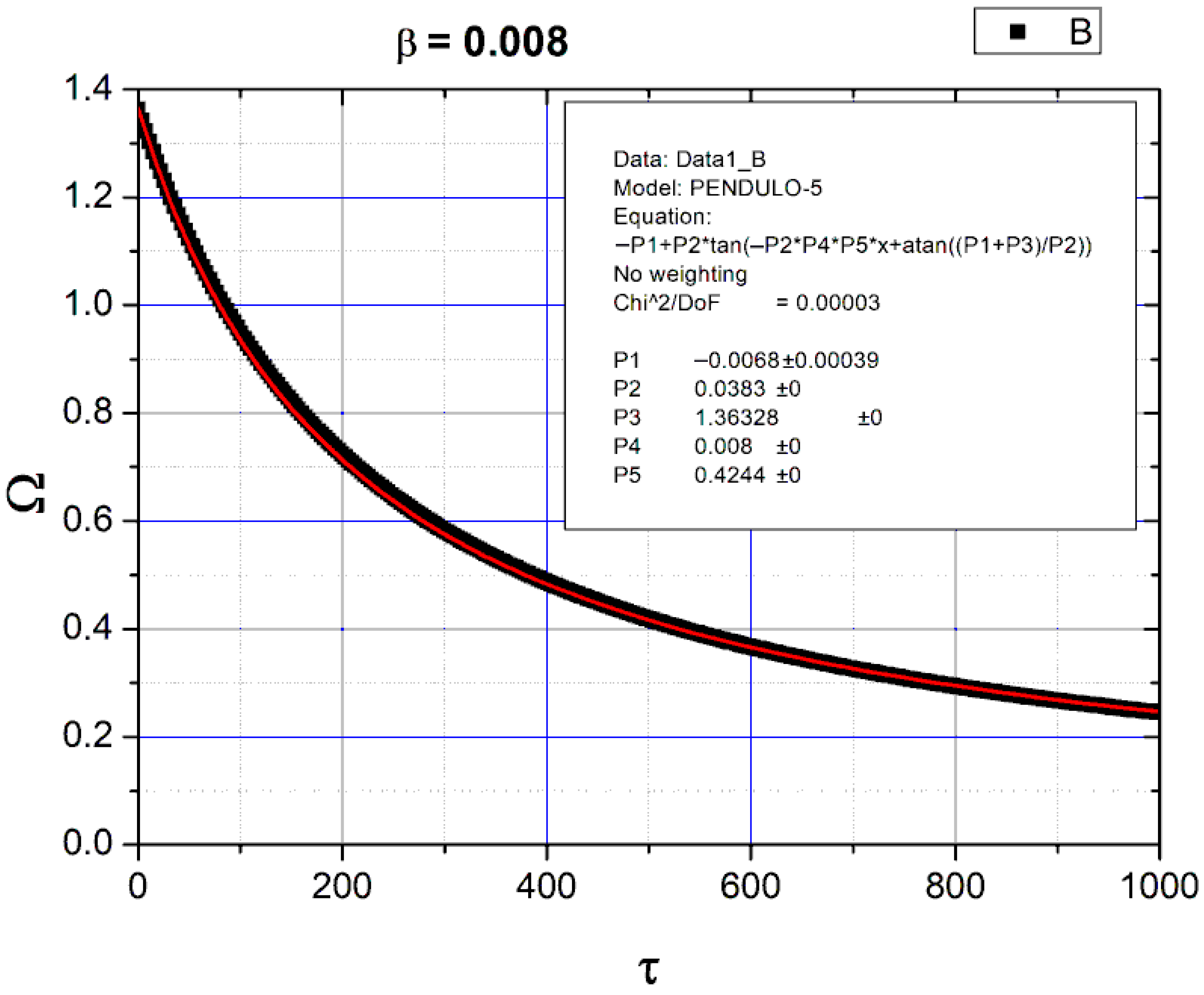
To adjust data we used a complete model designated by PENDULO-5 with five parameters:
Ω = P 1 + P 2 t g P 2 P 4 P 5 τ + a r c t g P 1 + P 3 P 2
The coefficient P3 is initial velocity, P4 is β, and P5 is β coefficient, expected to be 4 3 π .
P 1 = b 2 a P 2 = Δ 2 a P 3 = Ω 0 P 4 = β a = P 5 β b a = 2 P 1 c a = P 1 2 + P 2 2
Figure 14, Figure 15, and Figure 16 contain numeric data and adjusting parameters for three cases of a pendulum dropped from an angle of 1.5 rad and acted on only by a turbulent drag force with coefficients β = 0.04, 0.08, and 0.008, respectively.
We conclude that the turbulent force can be represented by the three-component vector:
a β = 4 3 π β b β = 0.0058 β c β = 0.00064 β
As expected, the b and c components are very small and can be neglected in usual calculations.

4.4. Conclusions for the Pendulum with Friction

The seven examples used in the last seven figures show that it is possible to univocally fit the obtained functions to the numerical data for angles much higher than those traditionally used in the approximation. sin ( θ ) approximately equal to θ .

Funding

This research received no external funding.

Data Availability Statement

The original contributions presented in this study are included in the article. Further inquiries can be directed to the corresponding author.

Conflicts of Interest

The authors declare no conflict of interest.

References

  1. Kidd, R.B.; Fogg, S.L. A simple formula for the large-angle pendulum period. Phys. Teach. 2002, 40, 81–83. [Google Scholar] [CrossRef]
  2. Parwani, R.R. An approximate expression for the large angle period of a simple pendulum. Eur. J. Phys. 2003, 25, 37. [Google Scholar] [CrossRef]
  3. Belendez, A.; Hernandez, A.; Marquez, A.; Beléndez, T.; Neipp, C. Analytical approximations for the period of a nonlinear pendulum. Eur. J. Phys. 2006, 27, 539–551. [Google Scholar] [CrossRef]
  4. Lima, F.M.S. Simple ‘log formulae’ for pendulum motion valid for any amplitude. Eur. J. Phys. 2008, 29, 1091–1098. [Google Scholar] [CrossRef]
  5. Beléndez, A.; Rodes, J.J.; Beléndez, T.; Hernández, A. Approximation for a large-angle simple pendulum period. Eur. J. Phys. 2009, 30, L25. [Google Scholar] [CrossRef]
  6. Johannessen, K. An approximate solution to the equation of motion for large-angle oscillations of the simple pendulum with initial velocity. Eur. J. Phys. 2010, 31, 511–518. [Google Scholar] [CrossRef]
  7. Butikov, E.I. Oscillations of a simple pendulum with extremely large amplitudes. Eur. J. Phys. 2012, 33, 1555–1563. [Google Scholar] [CrossRef]
  8. Benacka, J. Fast converging exact power series for the time and period of the simple pendulum. Eur. J. Phys. 2017, 38, 025004. [Google Scholar] [CrossRef]
  9. Lima, F.M.S. Simple but accurate periodic solutions for the nonlinear pendulum equation. Revis Bras. Ensino Física 2019, 41, e20180201–e20180202. [Google Scholar] [CrossRef]
  10. Abdulkareem, S.S.; Akgül, A.; Jalal, V.J.; Faraj, B.M.; Abdulla, O.G. Numerical solution for time period of simple pendulum with large angle. Therm. Sci. 2020, 24, 25–30. [Google Scholar] [CrossRef]
  11. Big-Alabo, A. Approximate periodic solution for the large-amplitude oscillations of a simple pendulum. Int. J. Mech. Eng. Educ. 2020, 48, 335–350. [Google Scholar] [CrossRef]
  12. Big-Alabo, A. Fifth-order AGM-formula for the period of a large-angle pendulum. Rev. Bras. Ensino Física 2023, 45, e20230014. [Google Scholar] [CrossRef]
  13. Erol, M.; Oğur, M. Teaching large angle pendulum via Arduino based STEM education material. Phys. Educ. IOP Publ. 2023, 58, 045001. [Google Scholar] [CrossRef]
  14. Fernandes, J.C. The Characterization of the Mechanical Harmonic Oscillator Extremum Envelope Shape According to Different Friction Types. Axioms 2025, 14, 554. [Google Scholar] [CrossRef]
  15. LabVIEWTM 2019 Is a Product from National Instruments. Available online: http://www.ni.com (accessed on 29 August 2025).
  16. ORIGINTM 7.0 Is a Product from Origin Lab—Data Analysis and Graphical Software. Available online: http://www.originlab.com (accessed on 29 August 2025).
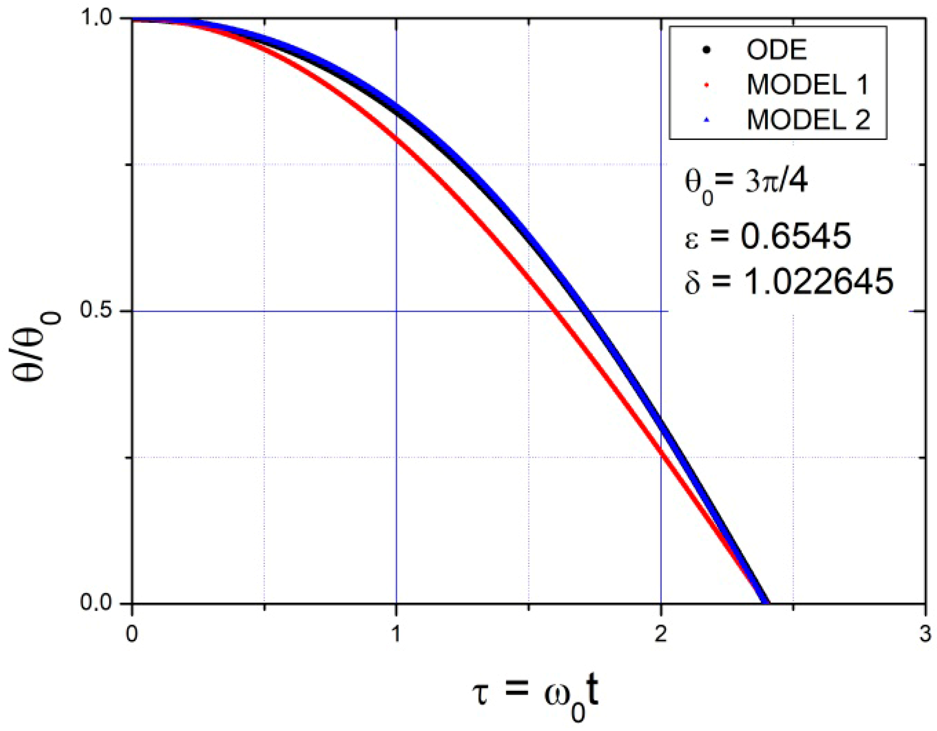
Figure 1. ODE are numerical data. Relative angle, for the initial quarter period of a pendulum dropping from an initial angle θ 0 = 3 π 4 .
Mathematics 13 02836 g001
Figure 2. ODE are numerical data. Relative angle, for the initial quarter period of a pendulum dropping from an initial angle θ 0 = π 2 .
Mathematics 13 02836 g002
Figure 3. ODE are numerical data. Both models describe very well the relative deviation during the initial quarter period of a pendulum dropping from an initial angle: θ 0 = π 4 .
Mathematics 13 02836 g003
Figure 4. ODE are numerical data. Velocity evolution, for the initial half period of a pendulum dropping from an initial angle θ 0 = 3 π 4 .
Mathematics 13 02836 g004
Figure 5. ODE are numerical data. Velocity evolution for the initial half period of a pendulum dropping from an initial angle θ 0 = π 2 .
Mathematics 13 02836 g005
Figure 6. ODE are numerical data. Velocity evolution for the initial half period of a pendulum dropping from an initial angle θ 0 = π 4 .
Mathematics 13 02836 g006
Figure 7. Function f μ and the adjusting third order polynomial.
Mathematics 13 02836 g007
Figure 8. Function f λ and the adjusting third order polynomial.
Mathematics 13 02836 g008
Figure 9. Function f β and the adjusting third order polynomial.
Mathematics 13 02836 g009
Figure 10. Pendulum dropped from 1.5 rad and acted on by a viscous force with coefficient λ = 0.008.
Mathematics 13 02836 g010
Figure 11. Pendulum dropped from 1.5 rad and acted on by a viscous force with coefficient λ = 0.08.
Mathematics 13 02836 g011
Figure 12. Pendulum acted on only by a Coulomb constant drag force with coefficient μ = 0.002 .
Mathematics 13 02836 g012
Figure 13. Pendulum acted on only by a Coulomb constant drag force with coefficient μ = 0.008 .
Mathematics 13 02836 g013
Figure 14. Pendulum acted on only by a turbulent quadratic drag force with β = 0.04.
Mathematics 13 02836 g014
Figure 15. Pendulum acted on only by a turbulent quadratic drag force with β = 0.08.
Mathematics 13 02836 g015
Figure 16. Pendulum acted on only by a turbulent quadratic drag force with β = 0.008.
Mathematics 13 02836 g016
Disclaimer/Publisher’s Note: The statements, opinions and data contained in all publications are solely those of the individual author(s) and contributor(s) and not of MDPI and/or the editor(s). MDPI and/or the editor(s) disclaim responsibility for any injury to people or property resulting from any ideas, methods, instructions or products referred to in the content.