Article

Safety Analysis of Subway Station Under Seepage Force Using a Continuous Velocity Field

1
Sinohydro Engineering Bureau 8 Co., Ltd., Changsha 410083, China
2
School of Civil Engineering, Central South University, Changsha 410075, China
*
Author to whom correspondence should be addressed.
Mathematics 2025, 13(15), 2541; https://doi.org/10.3390/math13152541
Submission received: 4 July 2025 / Revised: 31 July 2025 / Accepted: 5 August 2025 / Published: 7 August 2025

Abstract

Groundwater is an important factor for the stability of the subway station pit constructed in the offshore area. To reflect the effects of groundwater drawdown on the stability of the station pit, this work uses a surface settlement formula based on Rayleigh distribution to construct a continuous deformation velocity field based on Terzaghi’s mechanism, so as to derive a theoretical calculation method for the safety factor of the deep station pit anti-uplift considering the effect of seepage force. Taking the seepage force as an external load acting on the soil skeleton, a simplified calculation method is proposed to describe the variation in shear strength with depth. Substituting the external work rate induced by self-weight, surface surcharge, seepage force, and plastic shear energy into the energy equilibrium equation, an explicit expression of the safety factor of the station pit is obtained. According to the parameter study and engineering application analysis, the validity and applicability of the proposed procedure are discussed. The parameter study indicated that deep excavation pits are significantly affected by construction drawdown and seepage force; the presence of seepage, to some extent, reduces the anti-uplift stability of the station pit. The calculation method in this work helps to compensate for the shortcomings of existing methods and has a higher accuracy in predicting the safety and stability of station pits under seepage situations.

1. Introduction

The calculation of anti-uplift stability of deep station pits is a classic research topic in geotechnical engineering and plays an important role in ensuring the construction safety of subway stations. Currently, numerous methods have been developed to evaluate the stability of station pits, including finite element method (FEM) based on strength reduction techniques [1,2,3,4], the classic Terzaghi method, and the Prandtl method based on limit equilibrium theory [5,6]; and the multi-block rigid mechanism upper-bound method derived from bearing capacity theory [7,8,9].
The most widely used numerical methods for station pit stability assessment may be FEM. It provides a comprehensive framework to assess different aspects that affect the station pit stability and, therefore, leads to an accurate prediction. The elastoplastic finite element analysis implemented by Hashash and Whittle [1] revealed that the embedded depth and support conditions can significantly influence the failure models and the stability of the excavation base. Goh [2] and Faheem et al. [3] adopted the elastoplastic FEM with strength reduction technique to study the basal stability of excavations. Ukritchon et al. [9] adopted the numerical limit analysis method to investigate the stability of station pits, and predicted results show a good agreement with those by Goh [2] and Faheem et al. [3]. The results indicated that the station pit stability highly relies on the embedded depth and stiffness of the retaining wall. However, numerical methods also have intrinsic deficiencies, such as low computational efficiency induced by mesh density and model size, difficulty in selecting suitable constitutive models, which makes the reliability of the numerical simulation results require further discussion and verification in practical engineering.
Except for the numerical simulation method, theoretical analysis methods, such as the limit equilibrium method and the limit analysis method, play an important role in evaluating geotechnical stability problems. The limit equilibrium method is widely used in engineering practice. In the aspect of assessing the station pit stability, it mainly consists of the circular sliding method and the analysis method based on the bearing capacity model of the station. But it is not strict enough from the viewpoint of the theorem, as it analyzes the ultimate bearing capacity of soil through maximum resistance or moment calculations. Although computationally straightforward, it often fails to account for actual deformation patterns and soil mechanical properties. The limit analysis method, in virtue of its rigorous theorem and simple concept, has become the main analysis method for assessing geotechnical stability problems, including slope/retaining structure stability [10,11,12,13,14,15,16,17,18,19,20,21,22], tunnel face/roof stability [23,24,25,26,27,28,29,30,31,32], bearing capacity of foundation [33,34,35] and the anti-uplift stability of station pits [36,37,38,39,40,41].
In the aspect of stability analysis of station pits, Chang [36] extended the Prandtl failure mechanism from the bearing capacity foundation problem to the anti-uplift stability analysis of station pits. Faheem et al. [3] proposed Terzaghi and Prandtl mechanisms that consider the buried depth of hard soil layers and retaining walls. Based on this, Huang et al. [26] proposed a stricter Terzaghi and Prandtl mechanism. Considering the buried depth of the support structure, Huang et al. [39] and Du et al. [40] proposed a modified Prandtl mechanism. Although simplified mechanisms based on assumed geometry are computationally simple, there is still a certain gap compared to accurate numerical methods. Then, Huang et al. [8] adopted the upper bound method of block sets to construct the kinematically admissible velocity field for the anti-uplift stability problem of station pits, and the anti-uplift stability coefficient and failure surface characteristics of undrained clay station pits under various conditions were analyzed. Zhang et al. [41] extended this approach by accounting for pore pressure effects through seepage force work calculation along velocity discontinuity boundaries.
To address deformation discontinuity limitations, Osman and Bolton [42] proposed a mobilizable strength design method and established a continuous velocity field. The surface settlement formula is assumed to be a cosine function curve. Wang et al. [43] modified the continuous deformation velocity field to account for the surface settlement induced by the excavation. A Rayleigh distribution empirical surface deformation expression is adopted to describe the surface settlement. Both the groundwater seepage force and surface surcharge are taken into consideration. Considering that the conventional basal stability analysis methods cannot reasonably evaluate the lateral resistance afforded by the wall, Huang et al. [44] presented a new failure mechanism to evaluate the basal stability of excavations with embedded walls in undrained clay based on the upper bound theorem. The proposed mechanism consists of a rigid block and three shear zones, and the horizontal reinforcing effects of wall penetration below the excavation base are considered. Moreover, the elastic strain energy stored in the wall is incorporated in the upper bound calculation to increase the stability of excavation. However, the analysis process of this procedure is so complicated that it cannot be directly used in practical engineering.
Current research predominantly neglects the destabilizing effects of seepage forces. In sandy soils, excessive hydraulic gradients reduce effective stress and shear strength, potentially triggering piping erosion. For soft clayey soils, despite lower permeability, seepage force may induce quicksand conditions leading to basal failure. These studies demonstrate that refined upper-bound solutions depend fundamentally on appropriate failure mechanism construction and velocity field selection. Therefore, this study adopts a relatively simple continuous velocity field to account for excavation anti-uplift failure. The significant seepage pressure and surface surcharge are incorporated into the analysis. An engineering application is conducted to demonstrate the applicability of the proposed procedure.

2. Methodology

2.1. Upper Bound Theorem

The upper bound theorem, based on Drucker’s postulate and the principle of virtual work, indicates that for any kinematically admissible velocity field, namely a failure mechanism, the limit failure load determined by the work rate performed by external forces and the strain energy of the soil must not be less than the actual limit failure load. The relationship between work and energy can be expressed as the following formula:
S T i V i dS + A X i V i dA A σ i j ε i j dA
where ε i j denotes plastic strain field; σ i j denotes the stress field; V i is the kinematic admissible velocity field; T i is the surface force on boundary S; X i is the body force in the region A.
The effect of station pit dewatering is regarded as the formation of a certain seepage pressure between the inside and outside of the station pit. In the discontinuous velocity field mechanism of the multi-block failure mechanism, Zhang et al. [41] decomposed the work rate induced by the seepage force into two parts, namely
W u = A u d ε i j S u n i v i dS
where the first item in Equation (2) represents the work rate performed by volumetric strain; the second item corresponds to the work rate performed by the seepage force on the boundary S.
For a continuous deformation velocity field, the velocity discontinuity does not exist at the boundary of the kinematical field; therefore, the total work rate induced by the seepage force is merely the work rate performed on the microelements of the continuously deformation soil. Based on the assumption of an ideal plastic body, without considering the influence of volumetric strain, ε i j = 0 , the work performed by the seepage force is
W u = A f s n i v i dA
where f s is the seepage force; n i is the cosine of the angle between the direction of soil element seepage force and the direction of velocity.
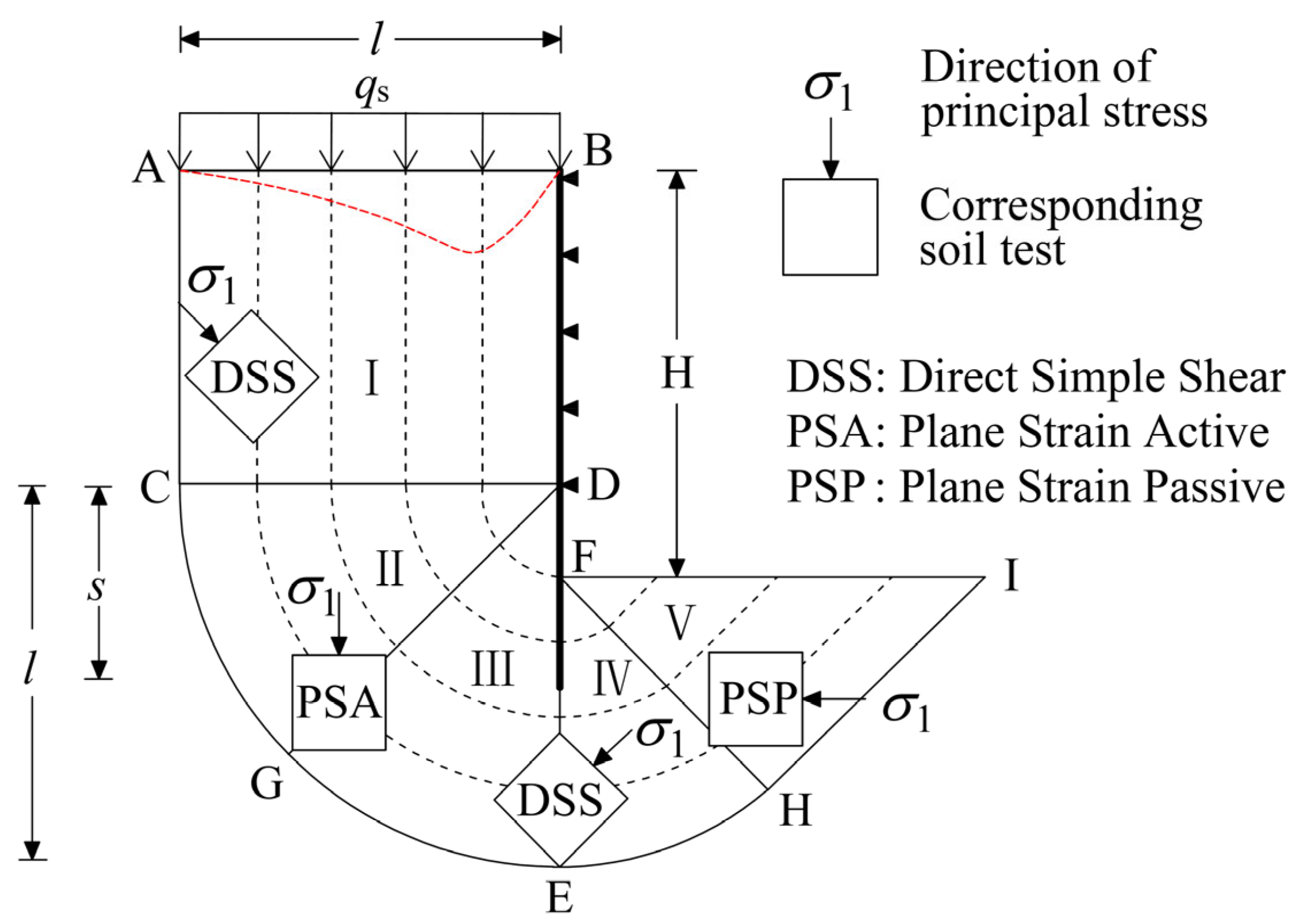
Because the retaining pile walls for deep excavation are usually designed in an impermeable form, a stable water level difference will form inside and outside the station pit after stable dewatering. The groundwater outside the station pit bypasses the bottom of the wall to form a stable seepage channel, and its seepage distribution is shown in Figure 1. Considering the seepage head loss, the water level difference Δh = Hw + h, the hydraulic gradient i = (Hw + h)/(Hw + 2s), and the seepage force fs = γwi under this hydraulic gradient. When the permeability of saturated cohesive soil is poor, the drainage process of the soil is hindered, and a certain amount of excess pore water pressure is formed. The calculation of the seepage generated by the excess pore water pressure can be obtained through practical measured values.

2.2. Continuous Deformation Field of the Station Pit

For multi-support excavation of deep station pits, there is a relationship between incremental displacement and surface settlement, as shown in Figure 2. Due to the complexity of deep excavation problems, it is still difficult to form a unified analytical form for the soil displacement field or velocity field caused by excavation. According to the existing theoretical research and statistical analyses, the settlement profile of station pits can be expressed in some commonly used functional forms, such as the cosine function form, the Rayleigh distribution form, and the variable Weibull distribution form. The empirical expression of these surface subsidence formulas (Equation (4)) is shown in Figure 1.
v = f x = δ m 1 2 1 cos 2 π x l δ m 4 x l exp 1 2 8 x 2 l 2 δ m β x l exp α x l exp α
Many investigations and statistics have shown that the settlement trough of station pits is closer to the Rayleigh distribution or the Weibull distribution. The deformation under this mechanism depends on the wavelength l. Wang et al. stated that the wavelength is affected by the embedded depth of the wall and the fixed end conditions, and the deformation influence range l is taken as
l = α s
in which s is the length from the bottom of the wall to the lowest internal support; α is the deformation parameter related to the softness and hardness of soils and the depth of embedment. If the wall is embedded into a stiff layer such that the wall tip is fixed, then α = 1 ; if the wall is short and is embedded into a soft layer, the wall deformation reaches the maximum at the tip of the wall, such that the wavelength can reach twice the wall length, and α = 2 ; for other cases where the wall is embedded into a medium stiff layer, the wavelength is 2 α 1 .
The orientation of the major principal stress direction within different shearing regions is presented in Figure 2. To facilitate the calculation of energies in limit analysis, the entire plastic deformation field is divided into five different regions. Zones I, III, and IV are the shearing region, the direction of the major principal stress inclines 45° with the horizontal direction. Zone II is an active region with the principal stress direction being vertical. Zone V is the passive zone with the principal stress direction being horizontal.
In a zone marked as DSS, the direction of the shearing is vertical or horizontal; thus, the ideal test on a vertical core is a direct simple shear test. In zones marked as PSA and PSP, the shearing happens at 45°. All plastic deformation fields in this work are continuously distributed. The deformation field of the station pit suffers from a uniformly distributed surface surcharge, qs.
Based on the Terzaghi mechanism, it is assumed that when the station pit undergoes uplift deformation, the bottom soil rotates around the lowest internal support, as shown in Figure 1. According to the surface settlement curve caused by the excavation of the station pit shown in the Rayleigh distribution form, the corresponding deformation mechanism of the station pit is determined, as shown in Figure 1. According to the Terzaghi mechanism, the deformation of the soil behind the retaining wall is transmitted along the flow field line direction. In the direction perpendicular to the “streamline”, the soil does not deform, and it is assumed that the soil inside the deformation mechanism undergoes uniform deformation, while the external soil does not deform. The velocity fields of each region are as follows:
The displacement increment in region ABCD is
v y = δ m 4 x l exp 1 2 8 x 2 l 2
where x is the horizontal distance from the wall to a random point.
The displacement increment in region CDE is
v θ = δ m 4 r l exp 1 2 8 r 2 l 2
where r is the radial distance from the center of the circular arc (D).
The displacement increment in region EFH is
v θ = δ m 4 r + h l exp 1 2 8 r + h 2 l 2
where r is the radial distance from the center of the circular arc (F), and h is the distance between the lowest support and the excavation level.
The displacement increment in region FIH is
v y = δ m 4 x + h l exp 1 2 8 x + h 2 l 2
where the x is the distance along the direction of FH between point F and the intersection with a plastic flow line. The engineering shear strains in the Cartesian coordinate system and polar coordinate system take the forms of
δ γ = v x y + v y x
and
δ γ = 1 r v r θ + v θ r v θ r
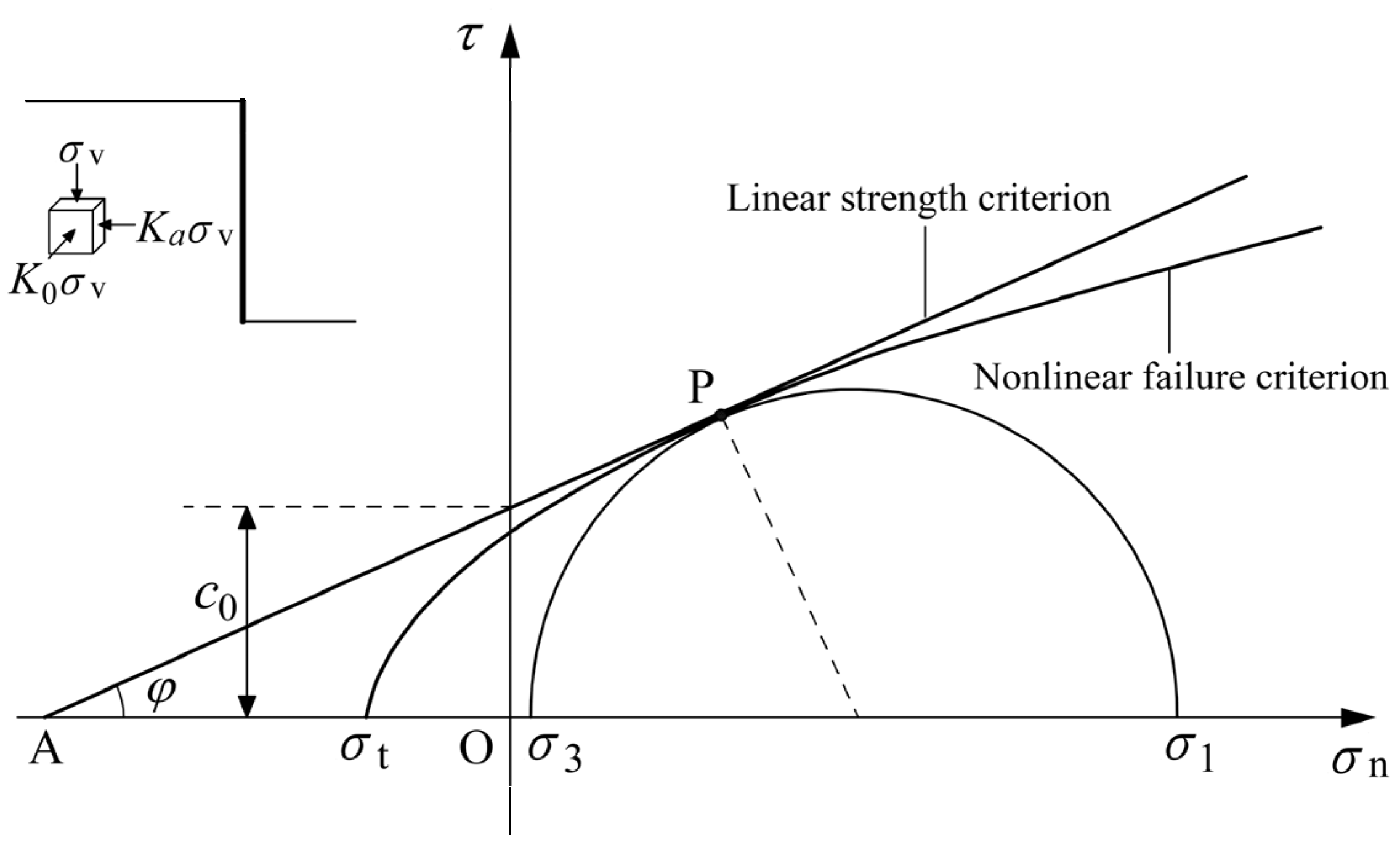
The shear strength of soils is assumed to obey the linear Mohr–Coulomb failure criterion, which is expressed as
τ = c 0 + σ n tan φ
Combining the principal stress form of the Mohr–Coulomb criterion, the shear strength can be expressed as
τ = c 0 + σ 1 + σ 3 2 σ 1 σ 3 2 sin φ tan φ
where σ 1 and σ 3 represent the major and minor principal stresses of the soils behind the retaining wall, they can be expressed as
σ 1 = γ z
σ 3 = K a γ z = tan 2 π 4 φ 2 γ z
where Ka is the active earth pressure coefficient, ∑γz is the self-weight stress, and the variation tendency with the depth is shown in Figure 1. Substituting Equations (14) and (15) into Equation (13), the shear strength of soils can be rewritten as
τ = c 0 + 1 + K a 2 1 K a 2 sin φ tan φ γ z
For sandy soil, ∑γz is taken as the vertical effective stress of the overlying soil; for cohesive soil, ∑γz is taken as the total vertical stress of the overlying soil (Figure 3).
Usually, the shear strength (c, tan φ) underwater should be reduced based on the strength above water, and the reduction ratio is taken as R according to the geotechnical test results. For sandy soil, ∑γz is taken as the vertical effective stress of the overlying soil; for cohesive soil, ∑γz is taken as the total vertical stress of the overlying soil. The shear strength can be expressed in the following form:
τ = c 0 + c 1 z
where c0 is cohesion and c1 is the increment of shear strength along with the depth.

3. Kinematic Analysis of the Station Pit

3.1. External Work Rate Calculation

For situations above the water level, only the gravity of soils and surface surcharge produces the work rate. For situations below the water level, the external forces include the self-gravity of soils, seepage force, and surface surcharge. Assuming the relevant soil parameters are as follows: material unit weight γm, natural unit weight γt, void ratio e, the saturated unit weight of the soil is γs = (γm + eγw)/(1 + e), and the floating unit weight γ’ = (γmγw)/(1 + e). For sandy soil, dewatering of the station pit may cause soil particle loss, which is macroscopically manifested as an increase in the soil’s void ratio.
The work rate induced by the self-gravity of soils can be calculated by the following double integral expression:
W γ = γ t 0 l 0 H H w h v y d x d y + γ s 0 l 0 H w v y d x d y + γ s 0 l r d r 0 π / 2 v θ cos θ d θ γ s 0 l h r d r 0 π / 4 v θ sin θ d θ γ s 0 l h 0 x v x sin π 4 d x d y
The work rate induced by the seepage force can be calculated by the following double integral expression:
W u = 0 l 0 H w v y f s d x d y + 0 l r d r 0 π / 2 v θ f s cos θ d θ + 0 l h r d r 0 π / 4 v θ f s sin θ d θ + 0 l h 0 x v x sin π 4 f s d x d y
The work rate induced by surface surcharge can be calculated by the following integral expression:
W q s = 0 l v y q s d x

3.2. Plastic Shear Energy Calculation

According to Equations (10) and (11), the increment of engineering shear strain in each region of the velocity field is
δ γ 1 = δ m 4 l 1 16 l 2 x 2 exp 1 2 8 l 2 x 2
δ γ 2 = δ m 64 l 3 r 2 exp 1 2 8 l 2 r 2
δ γ 3 = 4 δ m l h r 16 l 2 r + h 2 exp 1 2 8 l 2 r + h 2
δ γ 4 = δ m 4 l 1 16 l 2 x + h 2 exp 1 2 8 l 2 x + h 2
The plastic shear energy occurred in the region ABB’A’ of soils can be calculated by the following double integral expression:
E 1 = 0 l 0 H H w h δ γ 1 c 0 + c 1 y d x d y = 4 v m l c 0 H H w h + c 1 2 H H w h 2 0 l f 1 d x
where c0 = c, c1 = t.
The plastic shear energy that happened in region A′B′DC of soils can be calculated by the following double integral expression:
E 2 = 0 l 0 H w δ γ 1 c 0 + c 1 y + H H w h d x d y = 4 v m l c 0 H w 1 2 c 1 H w 2 + c 1 H h H w 0 l f 1 d x
where c0′ = R[k(γtγ)(HHwh) + c], c1′ = Rkγ.
The plastic shear energy that happened in region CDE of soils can be calculated by the following double integral expression:
E 3 = 0 l r d r 0 π / 2 δ γ 2 c 0 + c 1 r sin θ + H h d θ = 64 v m l 3 0 l r 3 π 2 c 0 + c 1 H h + c 1 r f 2 d r
The plastic shear energy that happened in region EFH of soils can be calculated by the following double integral expression:
E 4 = 0 l h r d r 0 π / 4 δ γ 3 c 0 + c 1 r cos θ + H d θ = 4 v m l 0 l h r π 4 c 0 + c 1 H + 2 2 c 1 r f 3 d r
The plastic shear energy that happened in region FGH of soils can be calculated by the following double integral expression:
E 5 = 0 l h 0 x δ γ 4 c 0 + c 1 x y sin π 4 + H d x d y = 4 v m l 0 l h c 0 + c 1 H x + 2 4 c 1 x 2 f 4 d x
where f 1 ~ f 4 are dimensionless functions, and take the form of
f 1 = exp 1 2 8 x 2 l 2 1 16 x 2 l 2
f 2 = exp 1 2 8 r 2 l 2
f 3 = h r + 16 h + r 2 l 2 exp 1 2 8 h + r 2 l 2
f 4 = exp 1 2 8 h + x 2 l 2 1 16 h + x 2 l 2
Substituting the external work rate in Equations (18)–(20) and plastic energy in Equations (25)–(29) into the energy equation of the upper bound method in Equation (1), the expression for the anti-uplift safety factor can be obtained as follows:
F S = E W γ + W u + W q s

4. Results and Discussion

4.1. Comparison

In order to validate the proposed procedure, the anti-uplift safety factor calculated by the proposed method is compared with the safety factors obtained from the Terzaghi mechanism, Prandtl mechanism, upper bound finite element method, and multi-block mechanism, based on the input parameters given in Table 1 and Table 2. The station pit stability problem studied in this work is based on cohesive-frictional soil materials; however, the existing solutions adopted for comparison are limited to clay. Therefore, the shear strength is merely provided by the cohesion of clay, and it is assumed that the shear strength varies linearly with depth. The underground water is not considered in the comparison.
It can be seen that the solution obtained by the present paper is similar to the solutions obtained from the upper bound finite element method and the multi-block upper mechanism, which verifies the feasibility of the proposed procedure in this paper. The solution obtained by the proposed method is smaller than the other two methods because the Rayleigh distribution function of the settlement curve of the soil behind the retaining wall is closer to the true settlement state of the soil. Therefore, it is more conservative to evaluate the anti-uplift stability of the station pit by the proposed calculation method. In general, the results agree well with the existing solution, and differences are within a reasonable range, which verifies the correctness of the calculation formula.

4.2. Parametric Studies

In order to investigate the influence of various factors, including surface surcharge qs, groundwater level H0, variation in void ratio Δe caused by construction drawdown, and wall length L on the anti-uplift stability of wide station pits, the factor of safety is calculated based on soil parameters: γ t = 18   kN / m 3 , γ s = 20   kN / m 3 , e = 0.5 , thus γ m = 25   kN / m 3 , c = 20   kPa , φ = 20 , and station pit geometry: H = 18   m , L = 26   m , s = 12   m , h = 4   m , q s = 20   kPa , H 0 = 2   m . In the process of parameter analysis, except for the parameters under study, the values of the rest of the parameters are taken as the above values.
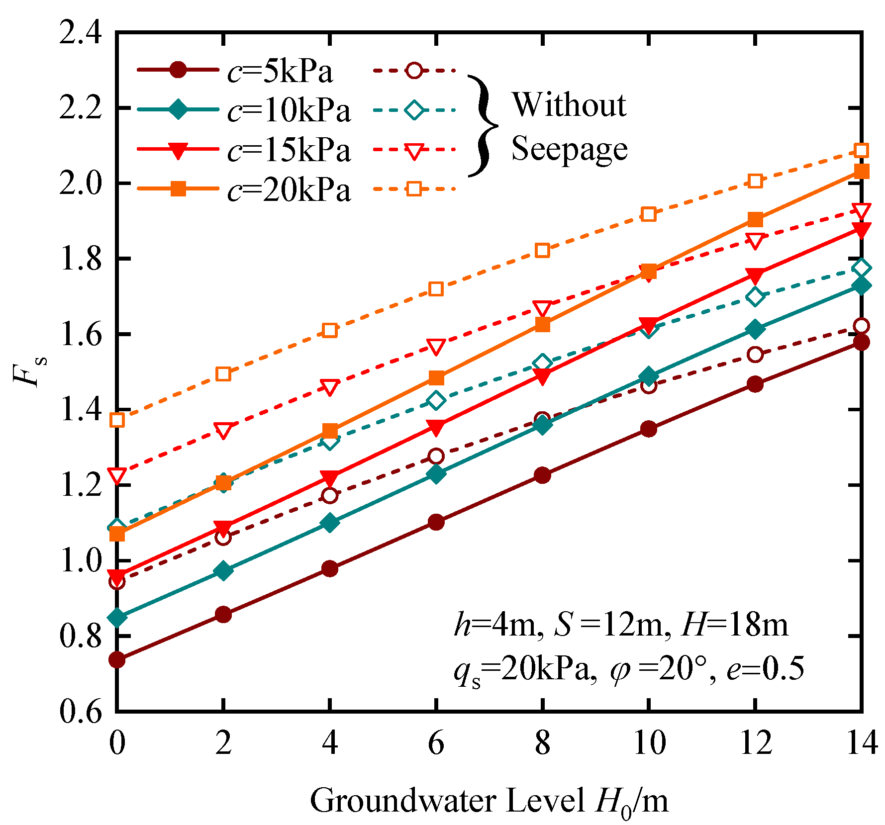
The groundwater is a critical factor that influences the stability of the station pit, especially in coastal areas where the groundwater level is very low. The water head difference inside and outside the station pit gradually increases as the station pit is excavated downwards towards the target depth. Therefore, the resultant seepage force acting on the soil skeleton will cause extra work in the permitted continuous velocity field. Figure 4 shows the influence of the buried depth of groundwater H0 on the factor of safety of the station pit under different cohesion. Note from Figure 4 that the anti-uplift factor of safety distinctly decreases with the decrease in buried depth of groundwater level outside the pit, which indicates that the groundwater has a significant influence on the factor of safety of the station pit. Moreover, the factor of safety calculated under seepage conditions is always smaller than that without seepage force. The factor of safety under a seepage situation gradually approaches the results without seepage as the groundwater level decreases.
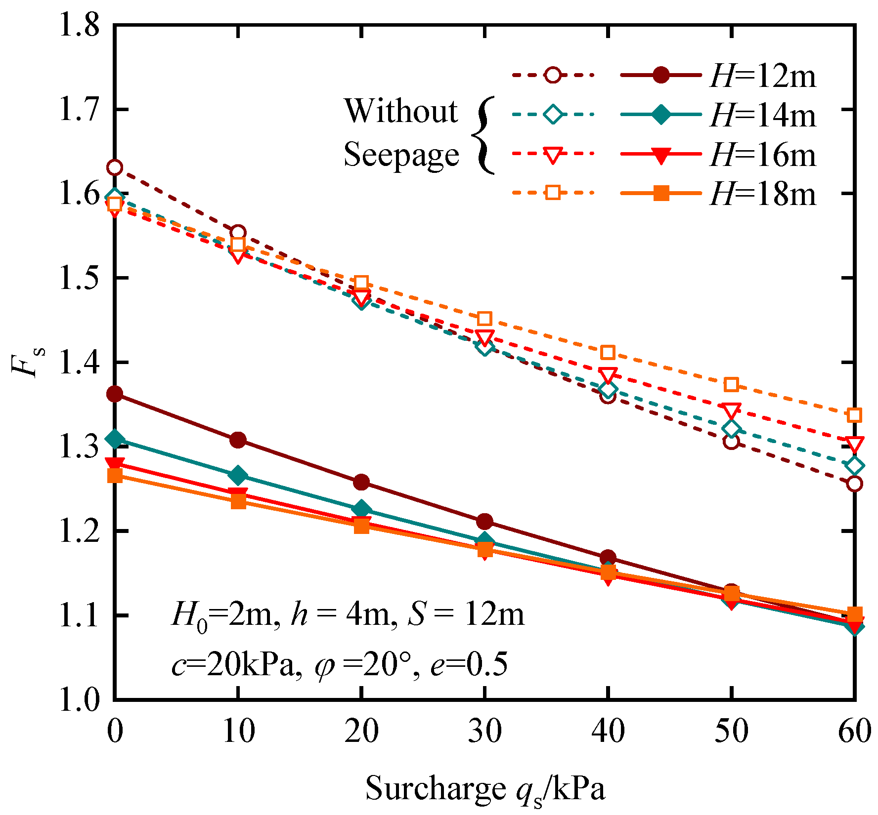
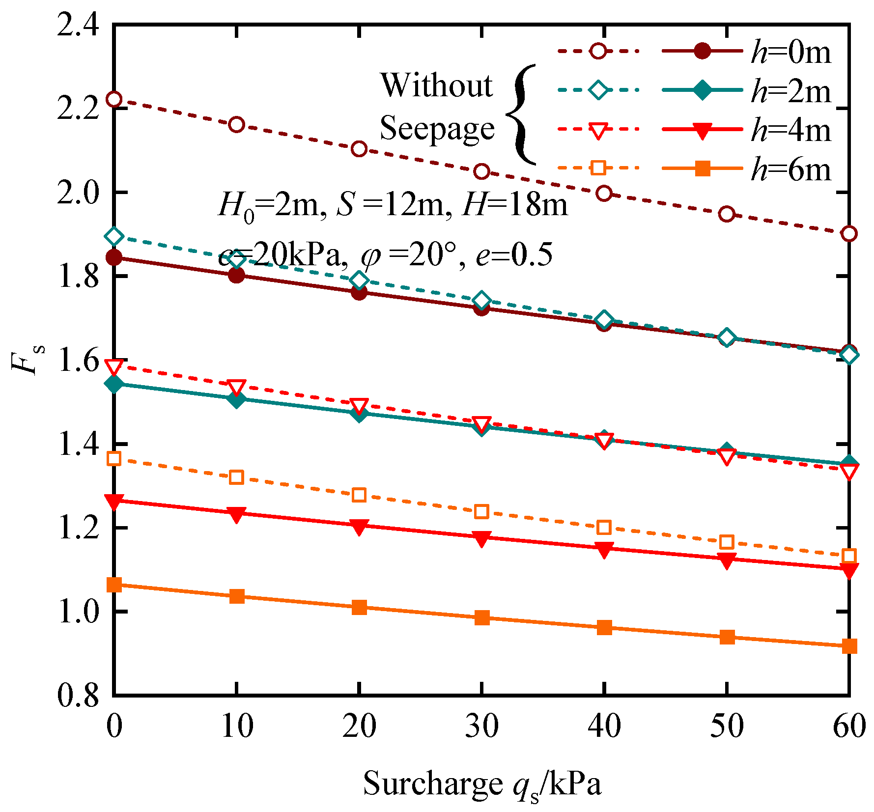
For the subway station pit, the surface surcharge usually exists. To investigate the influence of surcharge on the factor of safety, Figure 5 presents the variational trend of the factor of safety with surface surcharge under different excavation depths. It is expected that the surface surcharge has an adverse effect on the stability of the station pit, and the factor of safety decreases with an increase in surface surcharge in a linear form. Notably, the factor of safety calculated under no seepage situation is increased with the excavation depth; it is contrary to common sense that the deeper the excavation depth, the smaller the factor of safety. This is because the shear strength in Equation (16) is increased with the increase in the excavation depth, and the corresponding increment in the plastic energy is greater than the work rate performed by the external loading. When the seepage force is considered, the variational tendency is reversed, as shown in the solid lines.
Figure 6 illustrates the influence of surface surcharge and h (distance between the last support and excavation level) on the factor of safety. It can be found that the increase in distance h leads to an unsafe station pit when the excavation depth remains constant; moreover, the difference between the results calculated under the situation with and without seepage force is basically consistent. However, compared to the results in Figure 5, the factor of safety is more sensitive to the distance h than excavation depth H. Figure 7 investigates the influence of shear strength parameters, namely cohesion and the internal friction angle, on the stability of the station pit. It is noted that the station pit becomes stable as the shear strength parameters increase, which is consistent with common sense. The variational trend is nonlinear, with the gradient gradually decreasing as the internal friction angle increases. The influence of cohesion on the factor of safety is nearly linear. Moreover, the greater the internal friction angle, the greater the difference between the results calculated under the situation with and without seepage force.
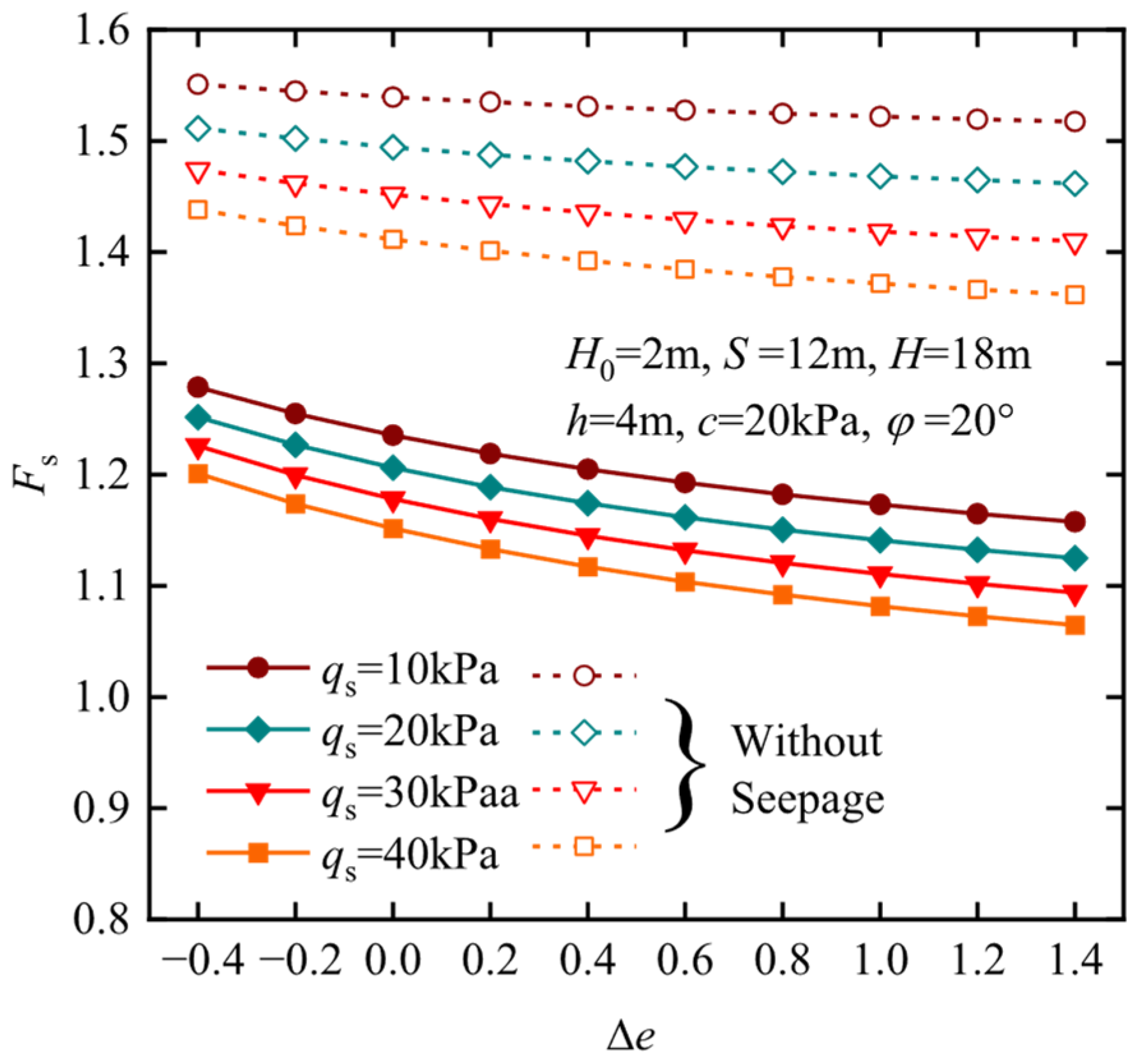
To reflect the influence of changes in the compactness of sandy soils, the average void ratio variation Δe can be used to quantitatively measure the process of changing particle composition, as shown in Figure 8. During the process of density change, the material density of the soil and the natural weight do not change, and the variation in void ratio only changes the soil parameters within the deformation influence range (the soil above water level is not affected), including the saturated weight, floating weight, and vertical effective stress of the soil. The variation in void ratio has a significant impact on the anti-uplift stability of station pits, and as the void ratio increases, the safety factor gradually decreases. In the case of seepage, the gradient of change in safety factor is higher than in the case without seepage force; however, the influence of surface surcharge on the factor of safety becomes more evident in the case of no seepage.
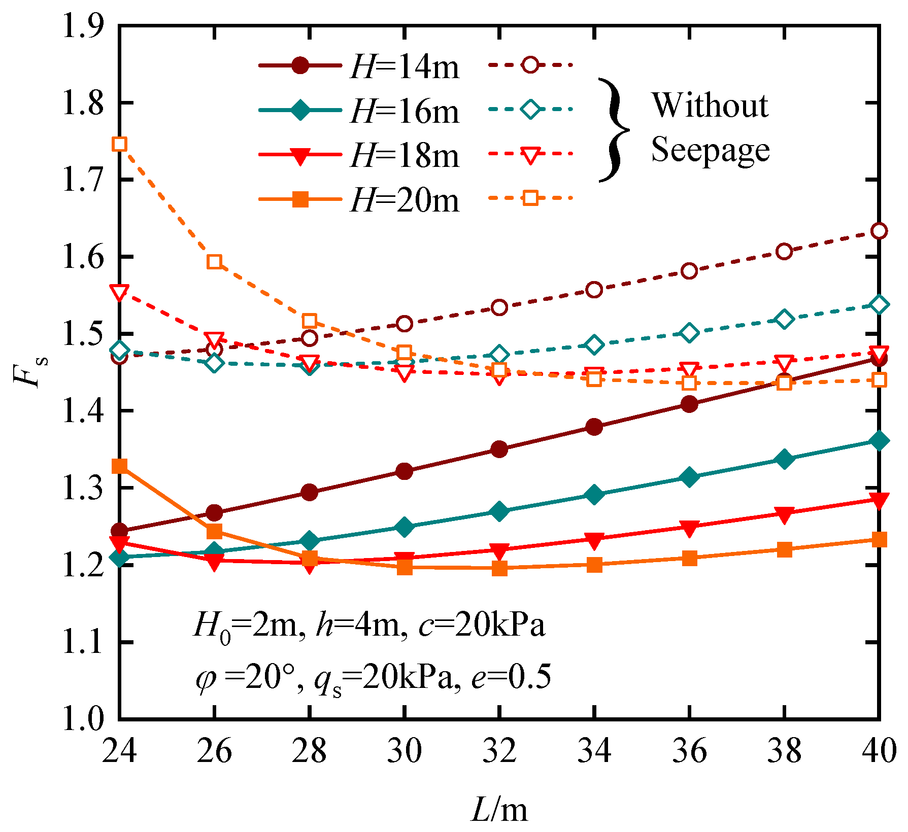
Assuming that the groundwater level remains constant and the wall is impermeable, Figure 9 shows the variation in the anti-uplift safety factor of the station pit with the length of the wall under excavation depths of 12 m, 14 m, 16 m, and 18 m. According to Figure 9, the anti-uplift safety factor varies in a nonlinear form with the length of the wall. When the excavation depth is small, the anti-uplift safety factor increases as the excavation depth of the station pit increases. Whereas, when the excavation depth is large, the safety factor firstly decreases and then increases as the wall length increases. This is because, although the excavation depth increases, the range of the velocity field l is reduced, resulting in an increase in safety factors. As the wall length increases, the range of the velocity field l is also increased accordingly, leading to a decrease in the safety factor, but as the wall length further increases, the safety factor transforms into an increasing tendency. Similarly, the same regularity as in the case of non-seepage conditions can be found.

4.3. Engineering Application

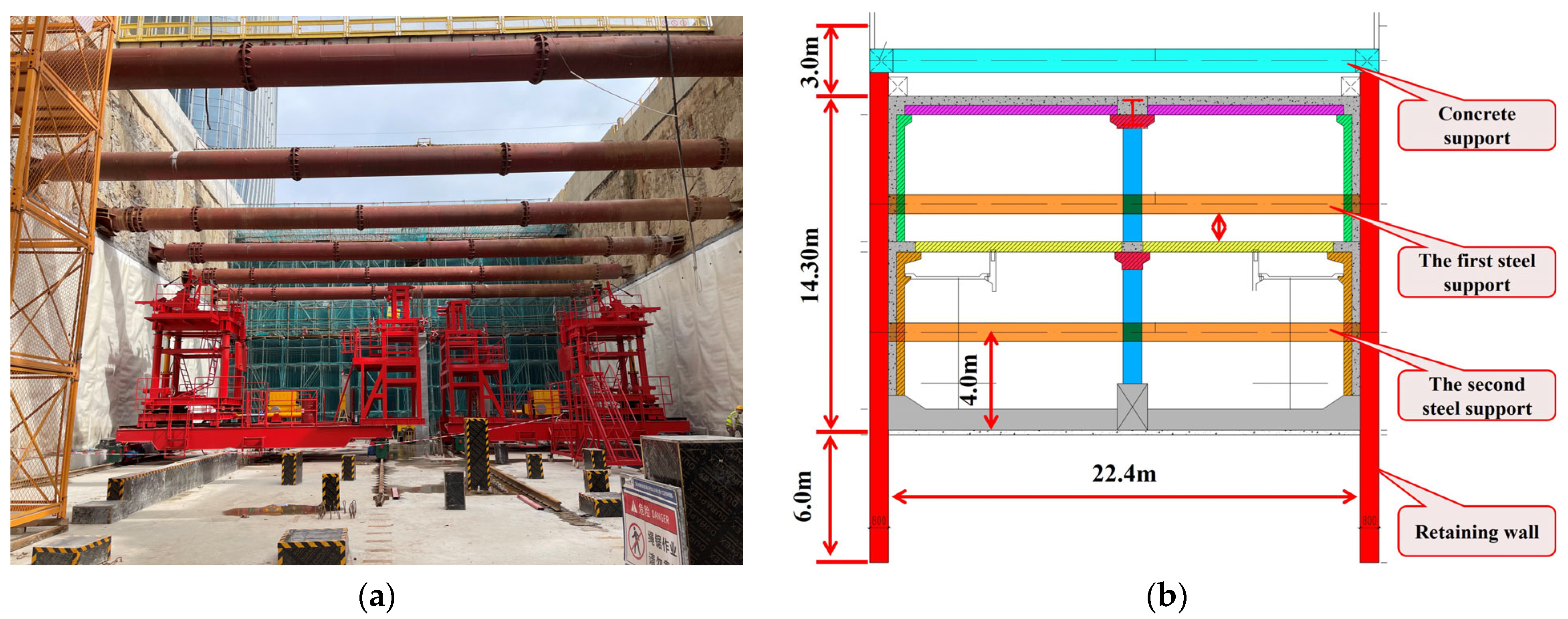
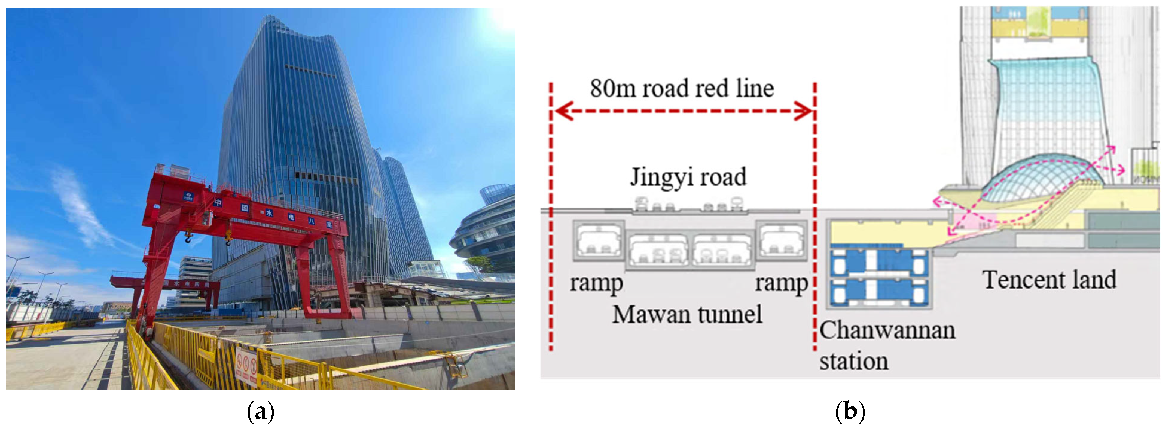
Based on the Shenzhen Metro Line 15 Chanwannan station project, this subsection applies the procedure proposed in this work to assess the stability of the station pit. The excavation depth of the foundation is H = 17.3 m, and three inner supports are exerted, including one concrete support and two steel supports. The specific geometry structure of the station pit is provided in Figure 10. According to the design, the wall length L = 23.3 m, embedded depth D = 6 m, and the distance between the second steel support and excavation level h = 4 m. Based on the survey report and test data, the depth of the groundwater level is about H0 = 1.0 m, which is very shallow since the subway station under construction is very close to the coast. The station is mainly located in the silty clay layer with shear strength parameters being c = 30 kPa, φ = 25°, void ratio being e = 0.8, and natural unit weight being γ = 19.5 kN/m3. The surface surcharge acting on the top of the station pit is very large because the Tencent Building is located less than 3 m east of the station, as shown in Figure 11. In addition, an extra construction load induced by the gantry crane should be considered. Therefore, the surface surcharge is taken as qs = 50 kPa.
The results calculated by the proposed procedure, considering seepage force, are Fs = 1.36, and the safety factor without the seepage force is Fs = 1.74, which means that the station pit under construction is stable and safe. The anti-uplift safety factors calculated using the Prandtl mechanism and the Terzaghi mechanism without considering seepage force are 1.45 and 1.69, respectively. The above comparison indicates that the anti-uplift safety and stability of the station pit are seriously reduced when the seepage force increases. The result obtained by the proposed continuous velocity field without considering the seepage force is close to the classic Terzaghi solution. The method proposed in this paper can better consider the influence of seepage.

5. Conclusions

This work selects a suitable surface settlement formula caused by deep excavation of station pits, constructs the continuous deformation velocity field, and derives the factor of safety of anti-uplift stability of station pits. The seepage situation is considered to gain more insight into the influence of variation in groundwater level and soil particle loss on the stability of the station pit. Through parameter analysis and engineering application, the following conclusions can be drawn:
(1)
The increase in seepage force caused by an increase in groundwater level and excess pore water pressure significantly reduces the anti-uplift stability of the station pit. Permeation pressure is an important factor influencing the stability of station pits.
(2)
The factors that affect the anti-uplift stability of the station pit include the following: seepage force (fs), soil shear strength (c and φ), embedded depth of retaining wall (D), and variation in soil particle (e). An increase in the embedding depth can increase the anti-uplift safety factor of the station pit when the excavation depth is small. When the excavation depth becomes larger, the anti-uplift safety factor might decrease due to the increase in the range of deformation influence.
(3)
The previous calculation methods ignore the influence of seepage force. This work attempts to extend the calculation method for the anti-uplift stability of deep station pits in geological formations that are sensitive to the influence of groundwater seepage pressure. Through engineering application and comparison, the predicted results of the proposed procedure without considering seepage are close to those of classic formulas, and considering seepage can better predict the stability of station pits.

Author Contributions

Methodology, Q.C.; Software, S.G.; Validation, Z.C.; Resources, D.Z.; Data curation, Q.C. and S.G.; Writing—original draft, Z.C.; Supervision, D.Z. All authors have read and agreed to the published version of the manuscript.

Funding

This work was supported by the project Research on Key Construction Technologies for Innovative Overlapped Subway Stations from Sinohydro Engineering Bureau 8 Co., Ltd.

Institutional Review Board Statement

Not applicable.

Informed Consent Statement

Not applicable.

Data Availability Statement

The data that support the findings of this study are available from the corresponding author upon reasonable request.

Conflicts of Interest

Author Zhufeng Cheng, Qiang Chen and Shuaifu Gu was employed by the Sinohydro Engineering Bureau 8 Co., Ltd. The remaining authors declare that the research was conducted in the absence of any commercial or financial relationships that could be construed as a potential conflict of interest.

Notations

A, Bnondimensional parameters δ m maximum of surface subsidence, m
ε i j plastic strain W γ work resulted from gravity, kJ
T i surface force on boundary S, kPa W u work resulted from u , kJ
σ i j stress tensor, kPa W q s work resulted from q s , kJ
V i kinematic admissible velocity field, m/s τ shear strength of soils, kPa
X i distributed load, kPa γ unit weight of soils, kN/m3
u pore water pressure, kPa δ γ 1 ~ δ γ 5 engineering shear strain
f s seepage force, kPa K a active earth pressure coefficient
H 0 distance between surface and water level, m φ internal friction angle, °
H excavation depth, m c 0 cohesion, kPa
h distance between last support to excavation level, m c 1 gradient of shear strength, kN/m3
H w H−h−H0, m q s surface surcharge, kPa
l influence range of excavation, m; k nondimensional parameter
s length from the bottom of the wall to the lowest internal support, m E 1 ~ E 5 plastic shear energy, kJ
α deformation parameter σ v vertical effective stress, kPa
v surface subsidence, m B foundation width, m
evoid ratio γ t effective weight of soils, kN/m3

References

  1. Hashash, Y.M.A.; Whittle, A.J. Ground movement prediction for deep excavations in soft clay. J. Geotech. Eng. 1996, 122, 474–486. [Google Scholar] [CrossRef]
  2. Goh, A.T.C. Assessment of basal stability for braced excavation systems using the finite element method. Comput. Geotech. 1990, 10, 325–338. [Google Scholar] [CrossRef]
  3. Faheem, H.; Cai, F.; Ugai, K.; Hagiwara, T. Two-dimensional base stability of excavations in soft soils using FEM. Comput. Geotech. 2003, 30, 141–163. [Google Scholar] [CrossRef]
  4. Sun, W.; Zhang, W.; Han, L. Determination of groundwater buoyancy reduction coefficient in clay: Model tests, numerical simulations and machine learning methods. Undergr. Space 2023, 13, 228–240. [Google Scholar] [CrossRef]
  5. Zhong, J.H.; Yang, X.L. Seismic stability of three-dimensional slopes considering the nonlinearity of soils. Soil Dyn. Earthq. Eng. 2021, 140, 106334. [Google Scholar] [CrossRef]
  6. Yang, X.L.; Wang, J.M. Ground movement prediction for tunnels using simplified procedure. Tunn. Undergr. Space Technol. 2011, 26, 462–471. [Google Scholar] [CrossRef]
  7. Qin, H.; Huang, M.; Ma, S. Multi-block upper bound method for basal heave stability analysis of braced excavations in clay. Chin. J. Rock Mech. Eng. 2010, 29, 73–81. [Google Scholar]
  8. Huang, M.; Yu, S. Upper bound analysis of basal stability in undrained clay based on block set mechanism. Chin. J. Geotech. Eng. 2012, 34, 1440–1447. [Google Scholar]
  9. Ukritchon, B.; Whittle, A.J.; Sloan, S.W. Undrained stability of braced excavations in clay. J. Geotech. Geoenviron. ASCE 2003, 129, 738–755. [Google Scholar] [CrossRef]
  10. Yang, X.L.; Li, L.; Yin, J.H. Seismic and static stability analysis for rock slopes by a kinematical approach. Geotechnique 2004, 54, 543–549. [Google Scholar] [CrossRef]
  11. Li, Z.W.; Yang, X.L.; Li, T.Z. Static and seismic stability assessment of 3D slopes with cracks. Eng. Geol. 2020, 265, 105450. [Google Scholar] [CrossRef]
  12. Zhang, Z.L.; Yang, X.L. Unified solution of safety factors for three-dimensional compound slopes considering local and global instability. Comput. Geotech. 2023, 155, 105227. [Google Scholar] [CrossRef]
  13. Zhang, Z.L.; Yang, X.L. Pseudodynamic analysis of three-dimensional fissured slopes reinforced with piles. Int. J. Geomech. 2022, 23, 04022315. [Google Scholar] [CrossRef]
  14. Li, Z.W.; Yang, X.L. Three-dimensional active earth pressure under transient unsaturated flow conditions. Comput. Geotech. 2020, 123, 103559. [Google Scholar] [CrossRef]
  15. Li, Z.W.; Yang, X.L. Active earth pressure for soils with tension cracks under steady unsaturated flow conditions. Can. Geotech. J. 2018, 55, 1850–1859. [Google Scholar] [CrossRef]
  16. Zhang, Z.L.; Zhu, J.Q.; Yang, X.L. Three-dimensional active earth pressures for unsaturated backfills with cracks considering steady seepage. Int. J. Geomech. 2023, 23, 04022270. [Google Scholar] [CrossRef]
  17. Zhang, Z.L.; Li, Z.W.; Dias, D. Seismic stability of cracked rock slopes based on physics-informed neural networks. Int. J. Rock Mech. Min. 2025, 192, 106147. [Google Scholar] [CrossRef]
  18. Liu, S.; Wang, L.; Zhang, W.; Sun, W.; Fu, J.; Xiao, T.; Dai, Z. A physics-informed data-driven model for landslide susceptibility assessment in the Three Gorges Reservoir area. Geosci. Front. 2023, 14, 101621. [Google Scholar] [CrossRef]
  19. Li, Z.W.; Yang, X.L. Stability of 3D slope under steady unsaturated flow condition. Eng. Geol. 2018, 242, 150–159. [Google Scholar] [CrossRef]
  20. Li, T.Z.; Gong, W.P.; Tang, H.M.; Zhang, L.M. A meshed kinematical approach for 3D slope stability analysis. Int. J. Numer. Anal. Methods Geomech. 2022, 46, 2913–2930. [Google Scholar] [CrossRef]
  21. Yang, X.L.; Huang, F. Collapse mechanism of shallow tunnel based on nonlinear Hoek–Brown failure criterion. Tunn. Undergr. Space Technol. 2011, 26, 686–691. [Google Scholar] [CrossRef]
  22. Li, T.Z.; Pan, Q.; Dias, D. Active learning relevant vector machine for reliability analysis. Appl. Math. Model. 2021, 89, 381–399. [Google Scholar] [CrossRef]
  23. Zhong, J.; Yang, X.; Chian, S.; Chen, H.; Hou, C. Revisiting the face stability of rock tunnels in the Hoek–Brown strength criterion with tension cutoff. Int. J. Numer. Anal. Methods Geomech. 2024, 48, 2061–2084. [Google Scholar] [CrossRef]
  24. Li, T.Z.; Yang, X.L. New approach for face stability assessment of tunnels driven in nonuniform soils. Comput. Geotech. 2020, 121, 103412. [Google Scholar] [CrossRef]
  25. Xu, S.; Liu, J.; Yang, X.L. Pseudo-dynamic analysis of a 3D tunnel face in inclined weak strata. Undergr. Space 2023, 12, 156–166. [Google Scholar] [CrossRef]
  26. Xie, Y.; Zhou, D.; Liao, H.; Zhu, J. Failure Mode of Tunnel Face Under Transient Unsaturated Seepage with Temperature Influence. Mathematics 2025, 13, 1311. [Google Scholar] [CrossRef]
  27. Sun, W.; Liu, H.; Zhang, W.; Liu, S.; Gao, X. Investigation on overburden thickness considering face and anti-floating stability of shallow shield tunnel. Comput. Geotech. 2023, 160, 105562. [Google Scholar] [CrossRef]
  28. Zhong, J.H.; Hou, C.T.; Yang, X.L. Three-dimensional face stability analysis of rock tunnels excavated in Hoek-Brown media with a novel multi-cone mechanism. Comput. Geotech. 2023, 154, 105158. [Google Scholar] [CrossRef]
  29. Zhong, J.H.; Yang, X.L. Kinematic analysis of the three-dimensional stability for tunnel faces by pseudodynamic approach. Comput. Geotech. 2020, 128, 103802. [Google Scholar] [CrossRef]
  30. Yi, C.; Senent, S.; Jimenez, R. Effect of advance drainage on tunnel face stability using limit analysis and numerical simulations. Tunn. Undergr. Space Technol. 2019, 93, 103105. [Google Scholar] [CrossRef]
  31. Li, T.Z.; Dias, D.; Li, Z.W. Failure potential of a circular tunnel face under steady-state unsaturated flow condition. Comput. Geotech. 2020, 117, 103231. [Google Scholar] [CrossRef]
  32. Mollon, G.; Dias, D.; Soubra, A.H. Face stability analysis of circular tunnels driven by a pressurized shield. J. Geotech. Geoenviron. 2009, 136, 215–229. [Google Scholar] [CrossRef]
  33. Xu, S.; Zhou, D. An Analytical Framework for Assessing the Unsaturated Bearing Capacity of Strip Footings under Transient Infiltration. Mathematics 2023, 11, 3480. [Google Scholar] [CrossRef]
  34. Liu, J.; Xu, S.; Yang, X.L. Modified pseudo dynamic bearing capacity of strip footing on rock masses. Comput. Geotech. 2022, 150, 104897. [Google Scholar] [CrossRef]
  35. Yang, X.L.; Yin, J.H. Upper bound solution for ultimate bearing capacity with a modified Hoek–Brown failure criterion. Int. J. Rock Mech. Min. 2005, 42, 550–560. [Google Scholar] [CrossRef]
  36. Chang, M.F. Basal stability analysis of braced cuts in clay. J. Geotech. Geoenviron. 2000, 126, 276–279. [Google Scholar] [CrossRef]
  37. Zhang, W.G.; Goh, A.T.C.; Goh, K.H.; Chew, O.Y.S.; Zhou, D.; Zhang, R. Performance of braced excavation in residual soil with groundwater drawdown. Undergr. Space 2018, 3, 150–165. [Google Scholar] [CrossRef]
  38. Huang, M.; Yu, S.; Qin, H. Upper bound method for basal stability analysis of braced excavations in K0-consolidated clays. China Civ. Eng. J. 2011, 44, 101–108. [Google Scholar] [CrossRef]
  39. Huang, M.; Du, Z.; Song, C. Effects of inserted depth of wall penetration on basal stability of foundation pits in clay. Chin. J. Geotech. Eng. 2011, 33, 1097–1103. [Google Scholar]
  40. Du, Z.; Huang, M. Analysis for basal stability of braced excavation in nonhomogeneous and anisotropic clay. Rock Soil Mech. 2013, 34, 455–467. [Google Scholar] [CrossRef]
  41. Zhang, F.; Li, J.; Tang, Y. Basal-heave Stability of Excavations Considering Groundwater Level and Pore Water Pressure Fluctuations by Upper Bound Method. Rock Soil Mech. 2011, 12, 3653–3659. [Google Scholar] [CrossRef]
  42. Osman, A.S.; Bolton, M.D. Ground movement predictions for braced excavations in undrained clay. J. Geotech. Geoenviron. 2006, 132, 465–477. [Google Scholar] [CrossRef]
  43. Wang, M.; Zeng, Z.; Jiang, Y.; Liu, D. Upper Limit Analysis of Continuous Deformation Field Infiltration Force on Anti-uplift Instability of Foundation Pit. J. Railw. Eng. Soc. 2019, 36, 12–18. [Google Scholar]
  44. Huang, M.; Tang, Z.; Yuan, J. Basal stability analysis of braced excavations with embedded walls in undrained clay using the upper bound theorem. Tunn. Undergr. Space Technol. 2018, 79, 231–241. [Google Scholar] [CrossRef]
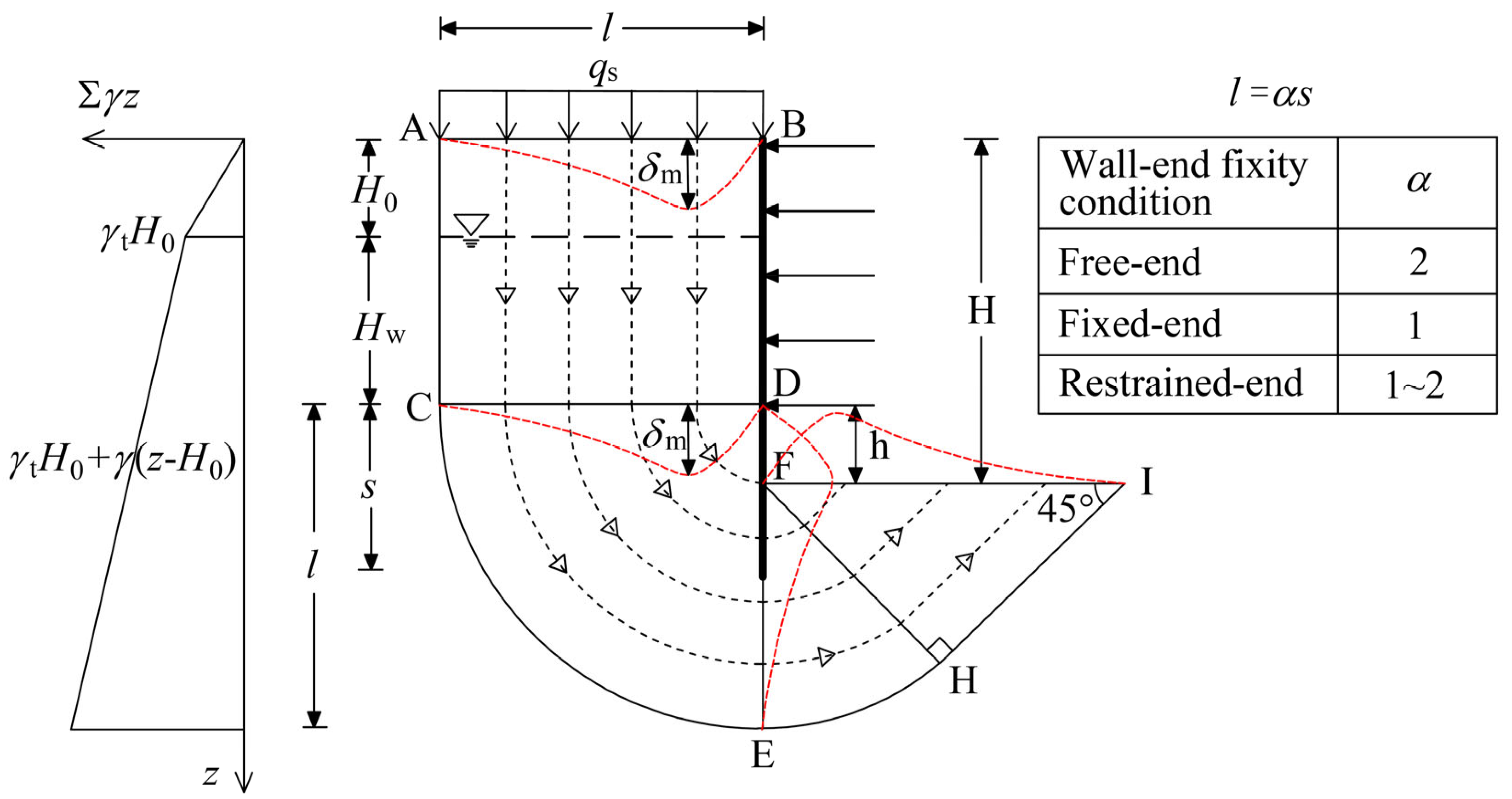
Figure 1. Plastic deformation mechanism of the station pit.
Mathematics 13 02541 g001
Figure 2. Rotation of principal stress direction.
Mathematics 13 02541 g002
Figure 3. Linear Mohr–Coulomb failure criterion and stress state.
Mathematics 13 02541 g003
Figure 4. Influence of the buried depth of groundwater level H0 and cohesion c on the factor of safety of the station pit.
Mathematics 13 02541 g004
Figure 5. Influence of surface surcharge qs and excavation depth H on the factor of safety of the station pit.
Mathematics 13 02541 g005
Figure 6. Influence of surface surcharge qs and h (distance between the last inner support and the excavation level) on the factor of safety of the station pit.
Mathematics 13 02541 g006
Figure 7. Influence of shear strength parameters on the factor of safety of the station pit.
Mathematics 13 02541 g007
Figure 8. Influence of void ratio and surface surcharge on the stability of the station pit.
Mathematics 13 02541 g008
Figure 9. Influence of wall length and excavation depth on the stability of the station pit.
Mathematics 13 02541 g009
Figure 10. Station pit (a) inner sight of the excavation site; (b) geometry and internal support layout.
Mathematics 13 02541 g010
Figure 11. Surrounding surface conditions of Chanwannan station: (a) photo of the excavation site; (b) schematic diagram of station pit cross-section.
Mathematics 13 02541 g011
Table 1. Foundation geometry and soil parameters.
Foundation WidthB40 m
Soil unit weightγ18 kN/m3
Internal friction angleφ
Undrained strength ratiocu/σv0.33
Distance of last support to excavation levelh2.5 m
Vertical effective stressσv(8.19z + 24.5) kPa
Table 2. Comparison of the proposed method with the existing solutions.
H/ms/mFactor of Safety, Fs
Terzaghi MechanismPrandtl MechanismUpper-Bound Finite Element Multi-Block MechanismThis Work
10.05.01.691.721.211.221.58
15.07.51.451.481.231.291.62
22.520.01.661.691.111.621.55
Disclaimer/Publisher’s Note: The statements, opinions and data contained in all publications are solely those of the individual author(s) and contributor(s) and not of MDPI and/or the editor(s). MDPI and/or the editor(s) disclaim responsibility for any injury to people or property resulting from any ideas, methods, instructions or products referred to in the content.