Article

Reinforcement Learning for Bipedal Jumping: Integrating Actuator Limits and Coupled Tendon Dynamics

by
Yudi Zhu
1,2,
Xisheng Jiang
1,2,
Xiaohang Ma
3,
Jun Tang
2,
Qingdu Li
1,2,3,* and
Jianwei Zhang
4
1
School of Optoelectronic Information and Computer Engineering, University of Shanghai for Science and Technology, Shanghai 200093, China
2
Institute of Machine Intelligence, University of Shanghai for Science and Technology, Shanghai 200093, China
3
Zhongyu Embodied AI Laboratory, Zhengzhou 450000, China
4
Department of Informatics, University of Hamburg, 20146 Hamburg, Germany
*
Author to whom correspondence should be addressed.
Mathematics 2025, 13(15), 2466; https://doi.org/10.3390/math13152466
Submission received: 30 June 2025 / Revised: 21 July 2025 / Accepted: 30 July 2025 / Published: 31 July 2025

Abstract

In high-dynamic bipedal locomotion control, robotic systems are often constrained by motor torque limitations, particularly during explosive tasks such as jumping. One of the key challenges in reinforcement learning lies in bridging the sim-to-real gap, which mainly stems from both inaccuracies in simulation models and the limitations of motor torque output, ultimately leading to the failure of deploying learned policies in real-world systems. Traditional RL methods usually focus on peak torque limits but ignore that motor torque changes with speed. By only limiting peak torque, they prevent the torque from adjusting dynamically based on velocity, which can reduce the system’s efficiency and performance in high-speed tasks. To address these issues, this paper proposes a reinforcement learning jump-control framework tailored for tendon-driven bipedal robots, which integrates dynamic torque boundary constraints and torque error-compensation modeling. First, we developed a torque transmission coefficient model based on the tendon-driven mechanism, taking into account tendon elasticity and motor-control errors, which significantly improves the modeling accuracy. Building on this, we derived a dynamic joint torque limit that adapts to joint velocity, and designed a torque-aware reward function within the reinforcement learning environment, aimed at encouraging the policy to implicitly learn and comply with physical constraints during training, effectively bridging the gap between simulation and real-world performance. Hardware experimental results demonstrate that the proposed method effectively satisfies actuator safety limits while achieving more efficient and stable jumping behavior. This work provides a general and scalable modeling and control framework for learning high-dynamic bipedal motion under complex physical constraints.

1. Introduction

In recent years, reinforcement learning (RL) has achieved remarkable success in high-dynamic motion-control tasks for robots, particularly demonstrating excellent policy-optimization capabilities in complex actions such as bipedal walking, running, and jumping [1,2]. However, despite their strong performance in simulation environments, these methods still face significant challenges when deployed on real hardware [3,4]. The core issue lies in the persistent “sim-to-real” gap, which manifests primarily in two aspects. First, the physical limitations of real-world actuators, including peak torque and instantaneous power constraints, are frequently oversimplified or neglected during training. Many RL-based approaches still rely on static and uniform torque limits, failing to account for the speed-dependent characteristics of power, thereby increasing the risk of motor overload or failure during actual execution [3,5]. Second, complex nonlinear features such as tendon-driven transmission, joint coupling, and elastic deformations are rarely modeled explicitly, resulting in control policies that fail to generalize to real-world systems [6,7].
To address the aforementioned challenges, numerous studies have proposed solutions from different perspectives. For instance, Rajeswaran et al. [8] introduced a residual RL framework based on expert demonstrations to construct more stable and efficient policies. Peng et al. [9] enhanced policy robustness by applying large-scale domain randomization. Yu et al. [10] and Xie et al. [11] improved simulation fidelity through system identification and online model adaptation, respectively. Haarnoja et al. [12] proposed the Soft Actor–Critic (SAC) algorithm, which achieved impressive performance in terms of sample efficiency and policy stability. However, these methods commonly overlook a critical issue: the lack of systematic modeling of actuator physical boundaries and complex structural characteristics. This omission leads to policies that are unaware of physical feasibility constraints during training, making them prone to generating infeasible actions in high-power, non-periodic tasks such as jumping.
Specifically, in the context of jumping control, several studies have attempted to develop high-performance policies within RL frameworks. For example, Bellegarda et al. [13] incorporated a power-clipping mechanism during execution to enhance real-world deployability. Zhang et al. [14] proposed a goal-guided and phase-based training framework to improve convergence efficiency, but their reward function failed to guide the policy to recognize actuator limits during training, which may result in unsafe actions during deployment. Atanassov et al. [15] utilized curriculum learning to achieve robust jumping behaviors. However, these approaches generally lack an integration of dynamic torque boundaries into the training process, limiting the policy’s ability to perceive and respond to motor states in real time. In addition, methods such as the PSTO framework proposed by Zhu et al. [16] and the DDPG-based gait optimization for CyberDog by Yan et al. [17], although effective in improving energy efficiency for low-dynamic tasks, rely heavily on periodic and stable motion patterns and thus struggle to generalize to explosive, high-power tasks like jumping. More importantly, many existing studies use reward functions that primarily focus on task performance but fail to explicitly model the actuator’s torque or power constraints [18]. As a result, the policies are unable to effectively learn and adapt to the actual physical boundaries of the actuators during training, significantly limiting their robustness and safety in real-world deployment [19]. In summary, while existing methods have alleviated parts of the sim-to-real gap to a certain extent, most have not systematically incorporated actuator physical limits and structural characteristics into the policy-learning process, making them inadequate for deployment in high-power tasks involving complex drive systems.
To address these limitations, this paper presents a physically consistent RL framework for tendon-driven bipedal robot jumping control. We introduce a linear transmission mapping from joint space to motor space to accurately model torque coupling caused by tendon-driven mechanisms. On this basis, we derive a speed-dependent dynamic joint torque boundary that reflects real actuator torque constraints and integrate it into the reward function to guide the policy toward physically feasible actions during training. To further narrow the sim-to-real gap, the model also incorporates tendon elasticity deviation and motor tracking errors to better approximate real-world conditions. The overall control framework proposed in this study is illustrated in Figure 1. The main contributions are summarized as follows:
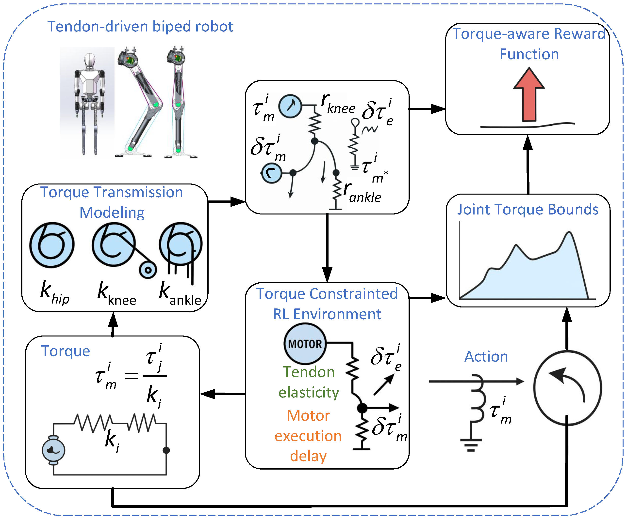
  • Torque Error-Compensation Modeling: By incorporating the effects of tendon elasticity and motor actuation delay, a dynamically adjustable joint torque safety boundary is derived as a function of joint velocity. This significantly enhances the simulation model’s fidelity and stability in approximating the real-world system;
  • Torque Transmission Modeling: A linear mapping model from joint space to motor space is constructed to account for the characteristics of tendon-driven bipedal robots. By defining the pulley radii of the hip, knee, and ankle joints, the model systematically captures the torque coupling effects introduced by the tendon-driven mechanism, laying a solid foundation for high-precision control;
  • Physically Consistent RL Framework: In the RL training process, this study integrates a dynamic torque boundary constraint into the reward function, guiding the policy to learn and comply with velocity-dependent torque limits. This approach allows the policy to implicitly adjust its outputs, ensuring efficient jumping while respecting the physical constraints of the actuators.
All experiments were conducted on our self-developed experimental platform. The results show that the proposed method generates stable and feasible control policies within actuator safety limits, effectively optimizing jumping performance and significantly enhancing the deployability and control quality of the policy. This work provides a theoretically sound and practically viable framework for applying RL to high-dynamic robotic tasks, laying a solid foundation for future policy design that integrates physical consistency.

2. Materials and Methods

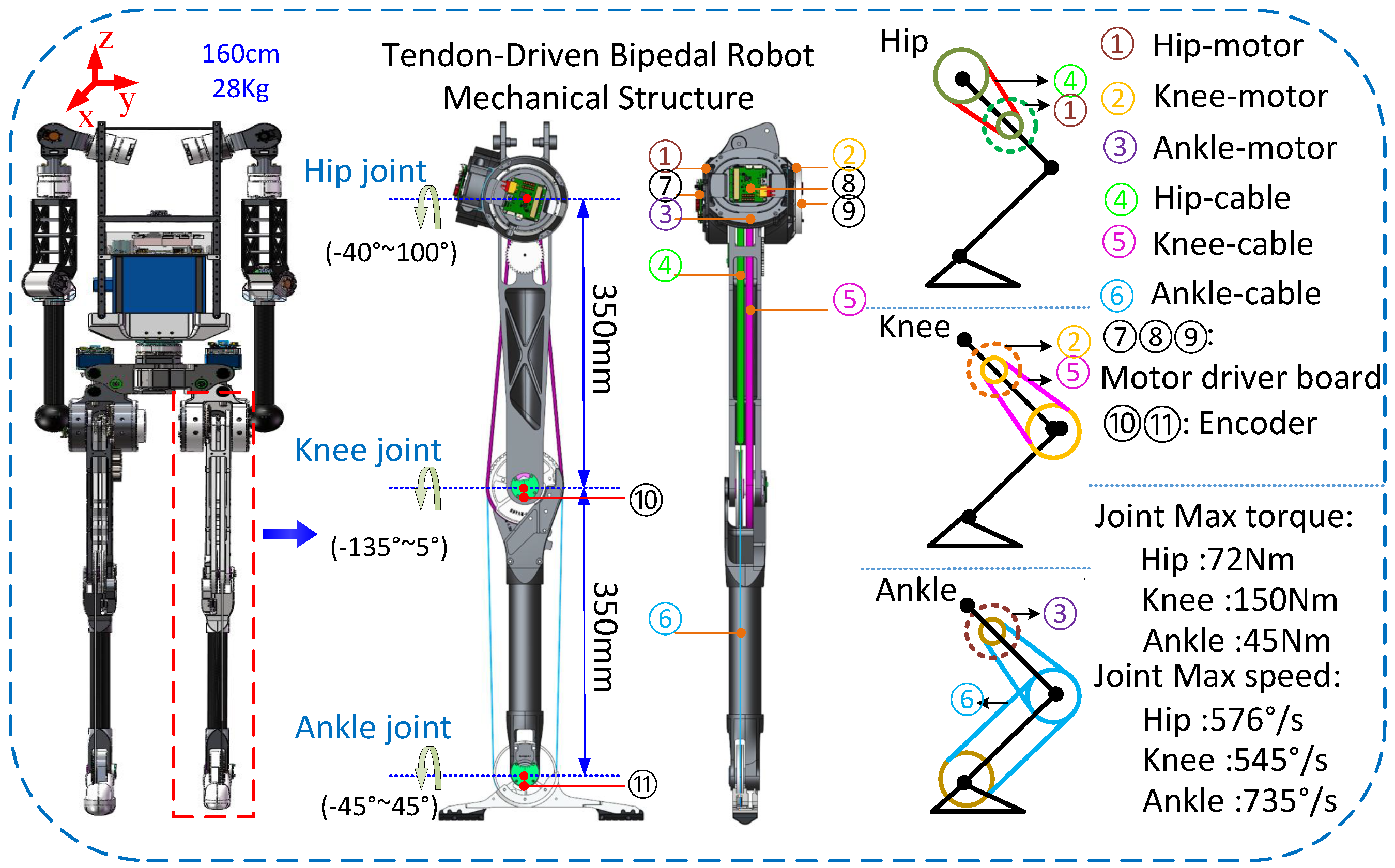
2.1. Mechanism Description for Robot

2.1.1. Overall Structural Design of the Robot

The bipedal robot platform used is illustrated in Figure 2. The robot stands 1.6 m tall, weighs approximately 28 kg, and has a total of 28 degrees of freedom (DOFs), 10 of which are allocated to the legs. Each leg has 5 DOFs, including 3 at the hip (pitch, abduction/adduction, and rotation), 1 at the knee (pitch), and 1 at the ankle (pitch). To enhance mobility and significantly reduce the load and inertia of distal limbs, tendon-driven mechanisms are employed at the robot’s key joints. This actuation method offers distinct advantages, including lightweight transmission, superior force control, and fast dynamic response. Owing to these features, tendon-driven mechanisms have been widely applied in robotics and bio-inspired manipulators. In scenarios where low mass, high compliance, and a high torque-to-weight ratio are essential, a tendon-driven mechanism enables agile, safe, and efficient motion control [20,21]. High-torque DC motors combined with tendon-driven systems are centrally mounted near the center of mass (COM) on both sides, and their output is transmitted to the knee and ankle joints via lightweight high-strength cables. This design reduces the structural mass of a single leg to below 3.6 kg.
The tendon-driven mechanism offers advantages such as compact structure, fast response, and high transmission efficiency, making it a critical foundation for achieving highly dynamic motions such as jumping [22]. The entire tendon-driven mechanism uses 1.5 mm diameter high-strength cables as the transmission medium, offering excellent tensile strength and fatigue resistance. From a mechanical perspective, a bi-directional winding configuration is employed along with a built-in tension adjustment mechanism, which effectively prevents cable slack and backlash. This ensures stable torque transmission and enables low-backlash joint control performance. The entire control system runs on a Linux-based real-time platform, with each joint equipped with an absolute encoder and operating under a unified position control mode. This setup ensures both precise joint control and robust real-time performance under complex task conditions.

2.1.2. Two-Stage Rope Drive System for the Knee Joint

The knee joint is actuated using a two-stage tendon-driven transmission with a remotely mounted motor, as shown in Figure 2. The knee motor is positioned at the upper thigh, and its torque is transmitted via a cable that passes through a guiding pulley and connects to an output pulley mounted on the knee joint. The torque transmission ratio is defined as:
k knee = r j knee r m knee
τ j knee = k knee · τ m knee
where r j knee and r m knee are the radii of the output and input pulleys, respectively, and τ j knee and τ m knee are the corresponding torques of the knee joint and motor. This configuration enables high torque output at the joint while significantly reducing the mass and inertia of the lower leg.

2.1.3. Knee and Ankle Combined Three-Stage Rope Drive System

To further reduce distal limb mass and improve actuation efficiency, this study proposes a novel three-stage coupled tendon-driven mechanism for the knee and ankle joints. Through a cascaded pulley transmission structure, a single motor can simultaneously drive both joints, forming a compact and efficient power transmission path. Specifically, the motor output is first transmitted to the knee-joint output pulley via the first-stage cable. The knee-joint output pulley is then connected to the ankle joint via a second-stage cable. Finally, a third-stage mechanism transfers the torque from the ankle pulley to the foot, completing the three-stage actuation loop. The overall torque transmission ratio of this system is given by:
k ankle = r j knee · r j ankle r m knee · r m ankle
τ j ankle = k ankle · τ m ankle
where r m ankle and r j ankle denote the radii of the motor pulley and the pulley of the ankle joint, respectively. This three-stage tendon-driven mechanism significantly reduces the load at the distal end by remotely locating the motor, thus improving joint responsiveness and landing compliance. Meanwhile, it features a compact structure, high transmission efficiency, and strong torque amplification capability, making it a key design to enable efficient and stable jumping control.

2.2. Torque Constraint Modeling

In the bipedal robot studied in this study, the leg adopts a hybrid tendon-driven mechanism. The transmission characteristics between joints are influenced by the radii of the pulley and the number of transmission stages. Unlike rigid direct-drive systems, tendon-driven joints transmit torque through multistage pulley systems, resulting in different torque transmission ratios between the motor and each joint. Taking the hip, knee, and ankle joints as examples:
  • The hip joint is directly actuated by the motor, with a torque transmission ratio of k hip = 1 ;
  • The knee joint is driven via a two-stage tendon-driven mechanism, with a ratio of k knee = r j knee r m knee ;
  • The ankle joint is driven through a three-stage tendon-driven mechanism, with a ratio of k ankle = r j knee · r j ankle r m knee · r m ankle ;
These ratios k i must be precisely considered in torque-constrained modeling, as well as in the formulation and solution of torque-constrained dynamics problems.

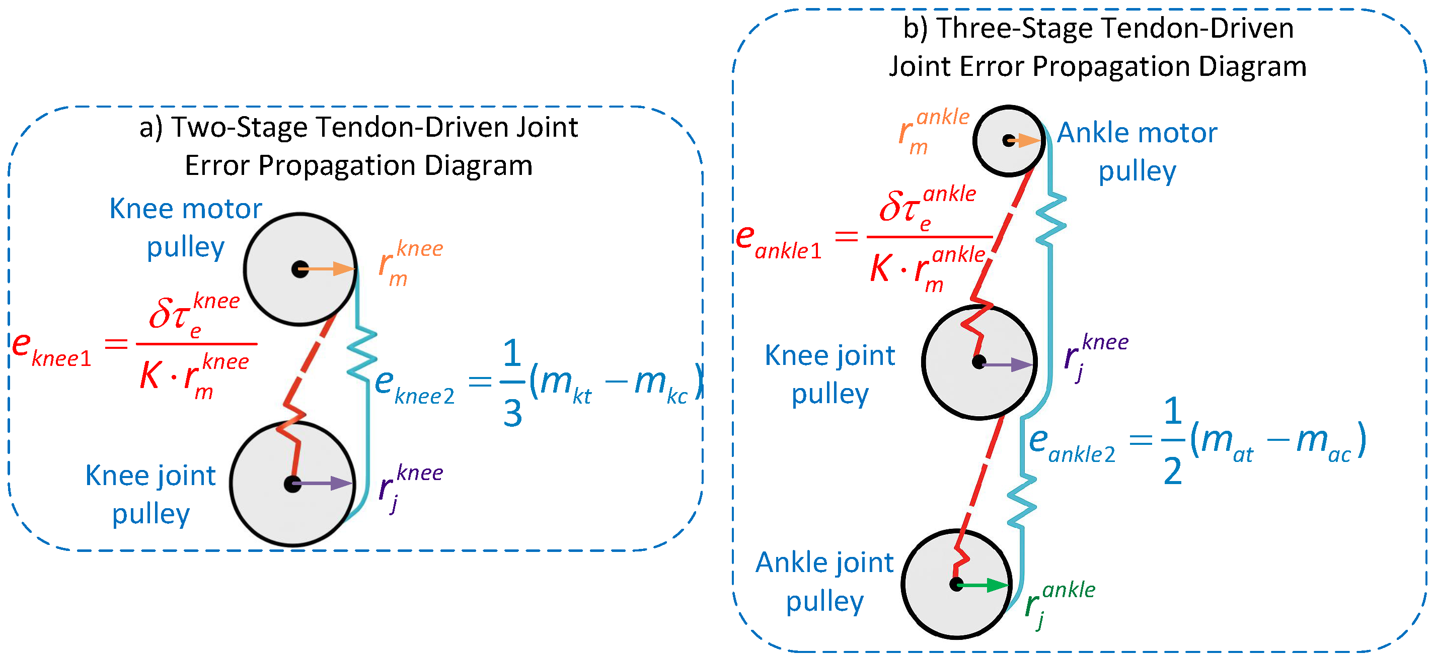
2.2.1. Leg Modeling Driven by Mixed Tendons

To accurately model the dynamic response characteristics of tendon-driven systems, this work systematically analyzes the torque deviations caused by tendon-driven elasticity and motor-control lag. A corresponding error-modeling framework is developed for both the knee and ankle joints to characterize their motion discrepancies.
(1)
Knee-joint two-stage tendon-driven error modeling.
The knee-joint motor is mounted at the upper thigh and drives the knee-joint output pulley through a single-stage cable transmission, forming a single-input–single-output structure. In this configuration, the elastic deformation of the cable causes a mismatch between the motor output and the actual knee-joint position, resulting in an angular deviation denoted as Δ j kc . This deviation is converted into torque error through the relationship between deformation and angular displacement. According to the tendon-driven dynamic model, the torque error between the knee-joint motor side and joint side is given by:
τ m knee = k p m kt m kc k d m ˙ kc = K · Δ m kc · r m knee 2 τ j knee = k p j kt j kc k d j ˙ kc = K · Δ j kc · r m knee · r j knee
where m kt and j kt represent the target positions of the knee-joint motor and joint, respectively; m kc and j kc denote their current positions. k p is the proportional gain, k d is the derivative gain. r motor and r knee are the radii of the motor pulley and knee-joint pulley, respectively, and K represents the tendon stiffness coefficient, which is 650 N/mm.
(2)
Ankle-joint three-stage tendon error modeling.
The control signal for the ankle joint must pass through a three-stage cascade mechanism, consisting of the knee output pulley and ankle input pulley, to reach the ankle joint. As a result, the total error originates from both the knee transmission segment and the ankle segment itself, forming a multi-stage compounded error system. The resulting torque error can be decomposed into the following two parts:
The torque error caused by elastic deformation between the ankle joint motor and the knee output pulley (denoted as τ mak );
The torque error caused by elastic deformation during transmission from the knee output pulley to the ankle joint (denoted as τ jka ).
The total torque error at the ankle joint τ j ankle is obtained by summing the above two components:
τ mak = k p m at m kc k d m ˙ kc = K · Δ j kc · r m knee · r j knee
Because the radii of the knee-joint motor and the ankle-joint motor are the same, we can get:
τ mak = k p m at m k c k d m ˙ kc = K · Δ j kc · r m ankle · r j knee
τ jka = k p j at j ac k d j ˙ ac = K · Δ j ac · r m ankle · r j ankle
τ j ankle = τ mak + τ jka = K · r j ankle · r j knee · Δ j kc + r j ankle · Δ j ac
Here, k p is the proportional gain, k d is the derivative gain. Δ j kc and Δ j ac represent angular position deviations propagated from the knee and ankle segments.

2.2.2. Modeling of Leg-Joint Error Compensation in Hybrid Tendon-Driven Mechanism

In a hybrid tendon-driven mechanism, due to the elastic deformation of cables and motor-control delays in the transmission path, significant discrepancies often arise between the motor target position and the actual joint output. To improve the motion-control accuracy of the knee and ankle joints in bipedal robots, this section analyzes and models the such errors.
The joint position error in a hybrid tendon-driven mechanism mainly consists of two components: the motor execution error and the elastic deformation error of the tendon. As shown in Figure 3, the error of the knee joint, denoted by e k , can be expressed as:
e knee = j kt j kc = e knee 1 + e knee 2
Here, e knee 1 represents the error caused by tendon elasticity, and e knee 2 denotes the deviation between the motor target and its current state. The coefficient 1 3 corresponds to a gear reduction ratio of 3:1 in the knee-joint drive system, used to map the motor-side position to the output side. The expressions are as follows:
e knee 1 = 1 3 m kc j kc
e knee 2 = 1 3 ( m kt m kc )
The error model for the ankle joint is similar to that of the knee. The coefficient 1 2 corresponds to a gear reduction ratio of 2:1 in the ankle-joint drive system, used to map the motor-side position to the output side. The total error e ankle is expressed as:
e ankle = j at j ac = e ankle 1 + e ankle 2
where
e ankle 1 = 1 2 m ac j ac + e knee 1
e ankle 2 = 1 2 ( m at m ac )
This error-modeling approach not only clarifies the structural sources of drive-system errors but also significantly enhances the stability and accuracy of joint control without increasing sensor cost.

2.3. Torque Constraint Modeling

In tendon-driven bipedal robots, actuators are constrained not only by their maximum torque limits during motion but also by their power output capabilities [23]. Compared to regular locomotion tasks, jumping demands rapid energy bursts, imposing stricter requirements on actuator power output [24]. Therefore, explicitly introducing torque constraints into the control formulation improves both the physical realism and stability of RL strategies.
For each joint i { hip , knee , ankle } , the motor power is defined as [25]:
P m i = τ m i · θ ˙ m i
where
  • τ m i is the motor output torque at joint i;
  • θ ˙ m i is the angular velocity of the motor;
  • P limit i is the maximum allowable power of the motor, as constrained by peak limits.
In a tendon-driven mechanism, motor torque is transmitted to joint torque via tendons and pulleys, yielding the following relation:
τ j i = k i · τ m i , θ ˙ m i = 1 k i · q ˙ j i
Here:
  • τ j i : actual output torque at joint i;
  • q ˙ j i : joint velocity;
  • k i : torque amplification factor for joint i, determined by pulley radii.
Substituting Equation (17) into the power definition yields the relationship between motor power and joint torque:
P m i = τ j i · q ˙ j i k i 2
Thus, under torque constraint, the theoretical upper bound of the joint torque becomes:
τ j i P limit i · k i 2 q ˙ j i + ε
where ε > 0 is a small positive constant to avoid division by zero. In Equation (19), a small positive constant ε is introduced to prevent division by zero when the joint velocity approaches zero. In this study, ε is set to 0.05 based on empirical observations to ensure numerical stability during policy training. Sensitivity analysis showed that values of ε in the range of 0.01 to 0.1 have minimal influence on torque limit behavior at moderate to high joint velocities, while providing stable bounds during near-zero velocities. This prevents the torque boundary from diverging and ensures consistent policy-learning dynamics across varying joint speeds.
In practice, due to elastic deformation in tendons and control delay in motors, there exists a deviation between target and actual torque. We therefore introduce the total torque error term ( i { knee , ankle } ):
δ τ i = δ τ e i + δ τ m i
The error terms can be computed using the motor encoders and the tension model. Applying Hooke’s law to relate tendon tension with elastic deformation yields [26]:
δ τ e i = K · e i 1 · r m i 2
The knee joint adopts a two-stage tendon-driven mechanism. Specifically, a section of cable connects the motor to the knee-joint pulley via a guide wheel, forming a single-input–single-output structure. When the cable is subjected to load, it experiences a slight elongation, resulting in a deviation between the actual output angle of the knee joint and the target angle, denoted as e knee 1 . This deviation leads to a torque error. The parameter K in Equation (22) denotes the tendon elasticity coefficient, which characterizes the relationship between cable deformation and torque loss. In our formulation, K is determined based on the mechanical specifications provided by the tendon manufacturer (e.g., stiffness per unit length under load). Specifically, we use a value of K = 650 N/mm, which corresponds to the elastic compliance observed in our tendon material under typical loading conditions.
δ τ e knee = K · e knee 1 · r m knee 2
The ankle joint is actuated by the ankle motor through a three-stage tendon-driven mechanism, where tendons connect the knee-joint output pulley and the ankle-joint input pulley. In this configuration, two segments of elastic tendons undergo elongation, and the resulting force is ultimately transmitted to the ankle joint.
δ τ e ankle = K · ( e knee 1 · r m knee 2 + e ankle 1 · r m ankle 2 )
δ τ m i = k p e i 2 k d m ˙ ic
The motor error is modeled as a proportion of the target torque. In our tendon-driven platform, the control signal sent to the motor is subject to execution latency and mechanical backlash. Based on the manufacturer specifications and internal calibration tests of our actuator system, we observed a tracking delay and attenuation corresponding to 5–10% deviation from the commanded torque across dynamic motions. Therefore, we introduced a conservative attenuation factor λ to approximate the torque-reduction effect. The damping term λ in Equation (25), reflecting residual motor-tracking error and dynamic delay, was empirically selected within the range [0.05, 0.1], after multiple hardware tests. Incorporating this factor during training improves the robustness of the learned policy, especially in real-world deployment where ideal motor responses are rarely achieved.
δ τ m i = λ i · τ m i , λ i [ 0.05 , 0.1 ]
Through the above modeling, the total error for each joint is obtained as:
Knee joint:
δ τ knee = K · e knee 1 · r m knee 2 + λ knee · τ m knee
Ankle joint:
δ τ ankle = K · ( e knee 1 · r m knee 2 + e ankle 1 · r m ankle 2 ) + λ ankle · τ m ankle
Combining the above, we define the maximum safe joint torque under torque constraint as:
τ j safe , i = P limit i · k i 2 q ˙ j i + ε k i · δ τ i

2.4. Reinforcement Learning Framework

To achieve efficient autonomous control of bipedal robot jumping, this study builds a RL training environment based on the isaacgym platform and proposes a physics-consistent control framework that explicitly incorporates torque boundaries and tendon-driven coupling constraints [27]. Compared to conventional policy-optimization methods that focus solely on trajectory performance, this work systematically integrates two key factors—actuator safety and structural coupling characteristics—into the reward function design, as shown in Figure 4.

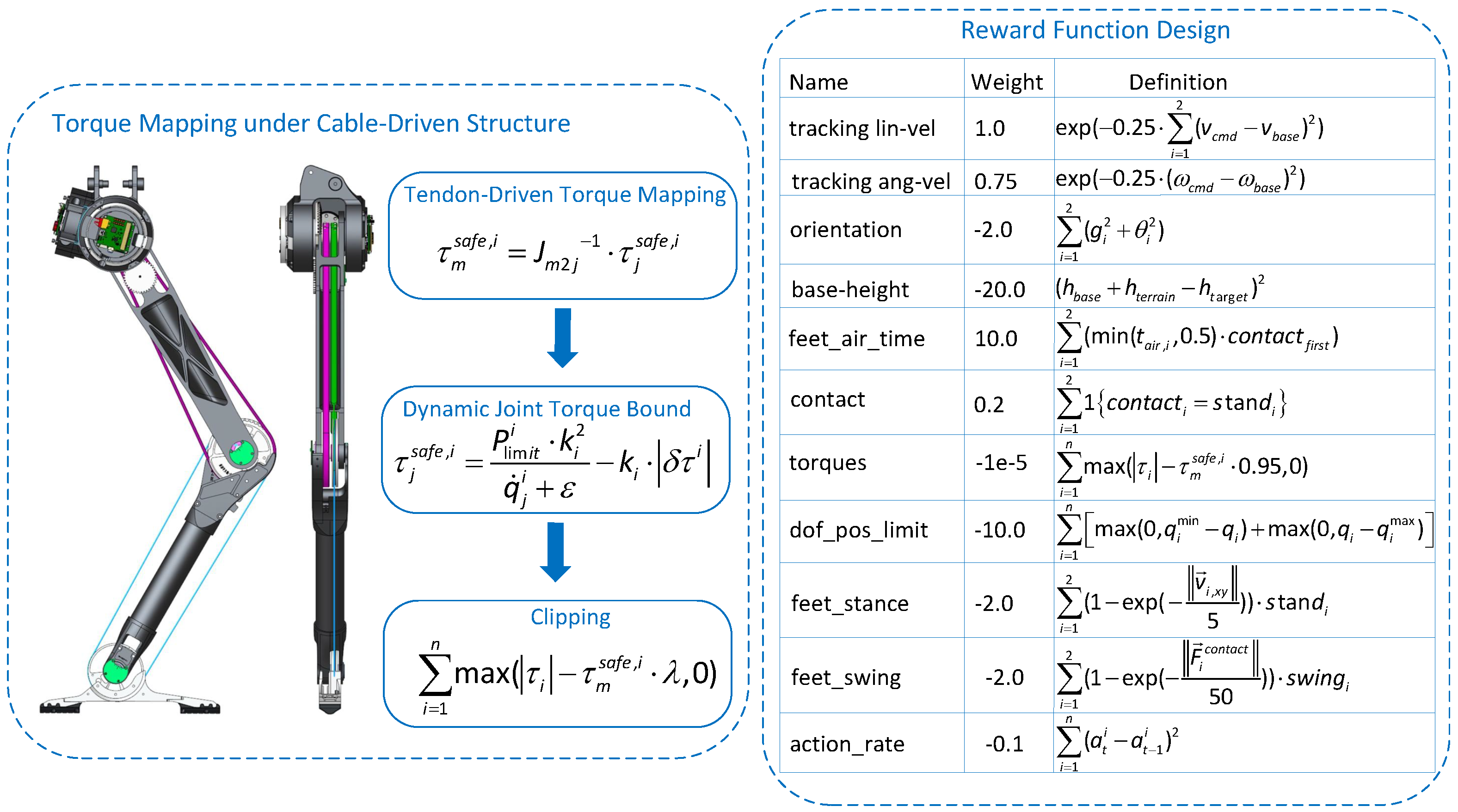
2.4.1. Torque Mapping in Tendon-Driven Mechanism

The leg actuation structure adopted in this work employs serial tendon routing to drive multiple joints, resulting in a significant coupling effect between motor output torque and the actual torque experienced at each joint. This coupling effect interferes with torque transmission between joints, often resulting in poor multi-joint coordination. To quantitatively characterize this structural influence, we establish a linear mapping from motor torques to joint-space torques. This formulation effectively improves coordination among joints during the jumping process, ensuring smoother and more stable motion. The mapping is defined as follows:
J m 2 j = 1.0 0.0 0.0 0.384 0.5 0.5 0.0 0.74 0.74
Each row of the matrix represents a linear combination of the torques from the three motors that contributes to the torque of a specific joint (hip, knee, and ankle). This coupling structure maps the desired joint-space torques τ j to the motor-space torques τ m , meaning that the control of a single joint will simultaneously affect the torque output of other joints. As a result, it increases the complexity of generating an effective control strategy.

2.4.2. Velocity-Dependent Torque Limit Modeling in Joint Space

In this study, although tendon elasticity inherently exhibits nonlinear characteristics, we adopt a linear mapping approach to simplify the coupling effects within the tendon-driven system. This simplification enables more efficient multi-joint control in reinforcement learning. To further address control errors caused by tendon elasticity, we incorporate a dynamic torque boundary model and an error-compensation mechanism, ensuring that nonlinear effects are adequately considered throughout the training process. The proposed dynamic torque boundary model is parameterized based on the motor’s torque-speed characteristics, effectively capturing the motor’s instantaneous output capability under varying rotational velocities. Specifically, the model adaptively adjusts the allowable joint torque according to the joint velocity, thereby dynamically constraining joint outputs. This enhances the controller’s ability to adapt to motor performance variations, particularly under highly dynamic tasks.
In high-power jumping tasks, joint velocities often exhibit rapid and abrupt variations. To prevent motor overload under such conditions, we construct a velocity-dependent dynamic torque limit model in joint space, denoted as τ j safe , i . This model is parameterized based on the motor’s torque-speed characteristics, capturing its real-time torque capacity at varying speeds. Specifically, the motor’s torque output is influenced by the joint velocity, which in turn dynamically adjusts the allowable torque at each joint. This mechanism enables the system to flexibly accommodate motor performance variations during highly dynamic movements. By modeling the nonlinear coupling between joint velocity, motor power, and torque constraints, the proposed approach significantly enhances the physical feasibility of the learned policy and improves actuator safety.
To make this constraint directly applicable in RL training, we perform an inverse mapping to convert it into motor-space limits:
τ m safe , i = J m 2 j 1 · τ j safe , i
Subsequently, after the policy network outputs the actions (i.e., target motor torques), a clipping operation is applied to constrain the actions within the aforementioned limits, thereby ensuring the physical feasibility of the policy output.

2.4.3. Reward Function Design

In this study, torque constraints and physical consistency principles are seamlessly integrated into the design of the RL reward function. The overall reward is formulated as a weighted sum of multiple sub-terms, covering aspects such as task accomplishment, posture and motion stability, energy consumption, and actuator safety [28]. Building upon classic control rewards—such as linear and angular velocity tracking, posture stabilization, and foot coordination—we introduce several torque-related terms that penalize actions exceeding dynamic torque limits. These additions significantly enhance the deployability of the learned policy on real-world robotic systems.
The weights in the reward function (as shown in Figure 4) were manually selected through iterative trial-and-error experiments. Specifically, the term base-height (with a weight of −20.0) directly incentivizes jumping height, while other components such as torques ( 1 × 10 5 ), dof_pos_limit (−10.0), and feet_stance/feet_swing (−2.0 each) enforce actuator safety and proper contact patterns. The weighting scheme was manually tuned to ensure that the agent prioritizes achieving sufficient vertical lift while respecting the physical feasibility of motion and contact dynamics. Larger penalties are assigned to violating joint limits and undesired contact states to avoid physically unrealistic behaviors. To evaluate the effectiveness of the reward structure in balancing task objectives and physical constraints, we performed ablation studies by removing key penalty terms. When the torques term was removed, the learned policy frequently generated torque commands exceeding actuator safety limits, risking hardware damage. Omitting the dof_pos_limit term led to joint overextension and unrealistic postures. Additionally, removing feet_stance and feet_swing terms caused asymmetric landings and unstable COM trajectories. In contrast, the full reward structure yielded stable and symmetric jumping with compliant joint behavior, demonstrating a well-balanced optimization between performance and physical feasibility.
When the output torque of the policy exceeds the soft power limit, the torque reward function applies a linear penalty, encouraging the policy to remain within the safe operating range while still meeting task requirements, as shown in Equation (31).
τ torque _ limits = i = 1 n max | τ i | τ m safe , i · λ , 0 , λ = 0.95
To facilitate reproducibility, we summarize key training configurations as follows. The policy and value networks adopt a 3-layer MLP structure with hidden layer sizes [256, 256, 128] and ReLU activation. We use the Proximal Policy Optimization (PPO) algorithm implemented with the Adam optimizer. The learning rate is set to 3 × 10 4 for both actor and critic networks, with a batch size of 64 and a discount factor γ = 0.99 . Each policy is trained for 3000 iterations with 4096 environment steps per iteration, totaling approximately 12 million steps. Training converges within 1.5 million steps, as monitored by reward plateaus and stable policy entropy. Model training and evaluation were conducted using Isaac Gym with GPU acceleration.
This work is the first to systematically incorporate tendon-driven mechanisms and torque-bound dynamic coupling modeling into a reinforcement learning (RL) framework. The proposed method integrates these effects into the reward function in a fully differentiable manner. By explicitly accounting for torque errors and coupling effects during training, the learned policy eliminates the need for online adaptation during deployment. Through dynamic adjustment within the RL process, the model can effectively accommodate actuator limitations in real-world tasks, thereby ensuring both system stability and control efficiency. This approach not only significantly improves the physical feasibility of the learned jumping policy and enhances actuator safety, but also provides a generalizable solution for controlling robots with complex actuation mechanisms.

3. Results

To systematically verify the effectiveness and practicality of the proposed RL jump-control framework, this paper focuses on two core innovations: tendon-driven coupling structure modeling and dynamic power boundary control. These innovations were tested on a self-developed physical robot, and key experiments were designed. Each experiment specifically evaluates the impact of different control elements on the strategy’s performance and physical feasibility, thus forming a closed-loop from theoretical hypothesis to practical effect validation.

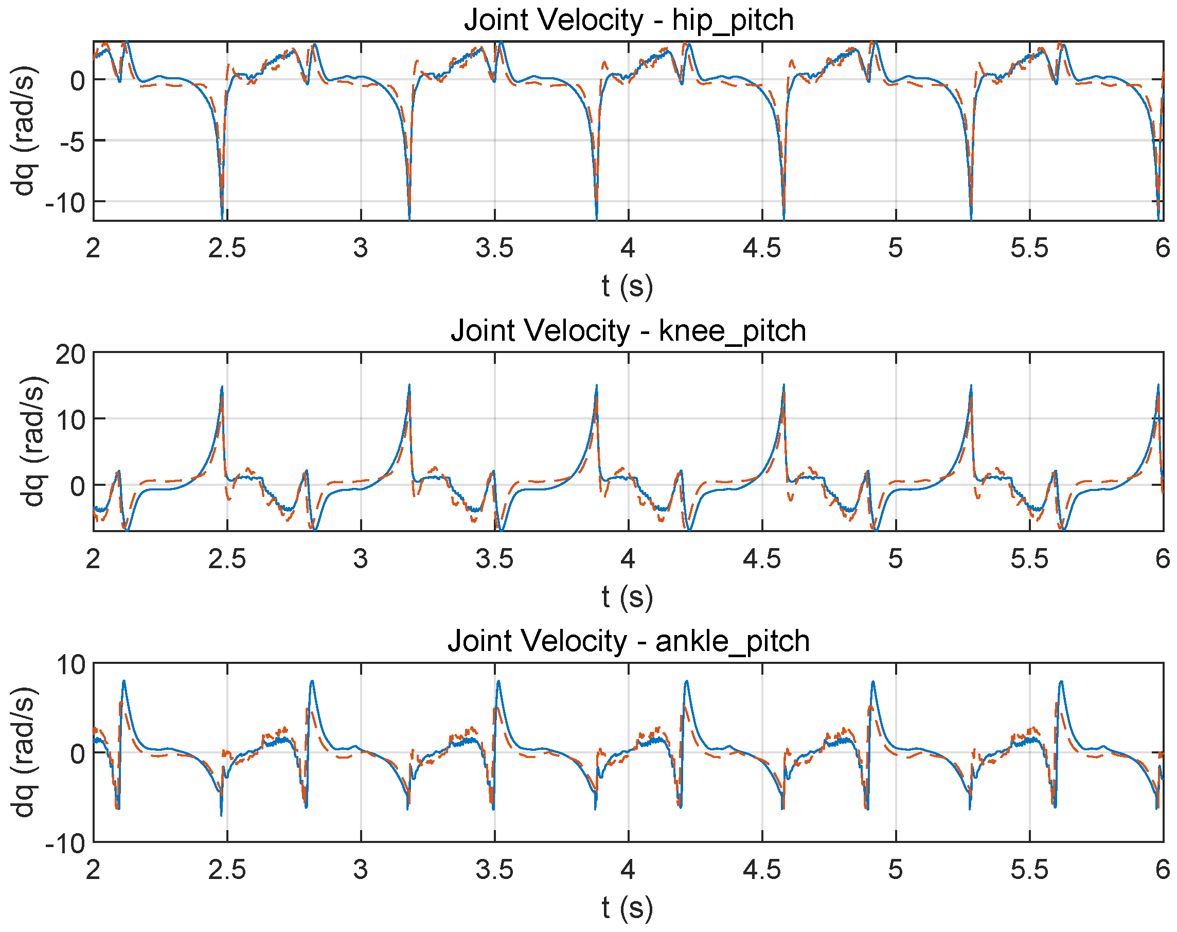
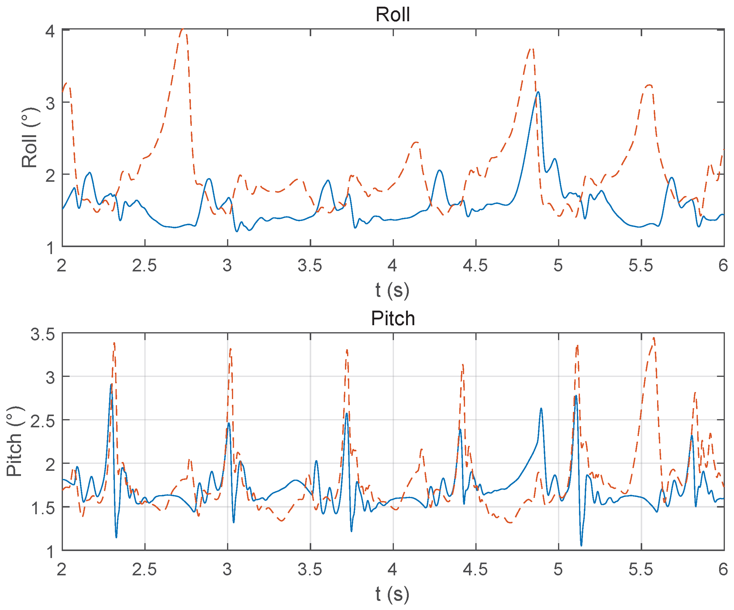
3.1. Torque Coupling Modeling Impact

In this experiment, we aim to investigate whether incorporating torque errors induced by the tendon-driven structure and modeling the motor–joint coupling can significantly enhance multi-joint coordination and jumping stability in RL. Specifically, the coupling effects between tendons, motors, and joints play a critical role in controlling high-dynamic tasks such as jumping in bipedal robots. Without adequate modeling of these interactions, joint-level control imbalances may arise, impairing the efficiency and stability of jumping behaviors. To this end, we design a comparative study between two control strategies: (1) direct joint torque control without modeling tendon-induced torque errors and motor–joint coupling; and (2) a control strategy that explicitly models both the torque errors and the coupling relationships during learning. Both strategies adopt the proposed velocity-dependent dynamic torque limiting. We evaluate performance across several key metrics, including joint torque variation, joint position trajectories, joint velocities, jump symmetry, foot height, and COM height. These indicators comprehensively reflect differences in jumping performance and physical feasibility across control strategies.
Experimental results are presented in Figure 5, Figure 6, Figure 7, Figure 8 and Figure 9, where the blue solid lines represent the performance of the strategy with coupling and torque error modeling, while the orange dashed lines correspond to the baseline without such modeling. The comparison reveals that incorporating physical coupling modeling significantly improves control performance. The proposed approach enables more accurate joint trajectory tracking, smoother velocity profiles, reduced torque overshoot, enhanced postural stability, and consistently higher jump heights. These findings strongly validate the effectiveness of embedding low-level physical modeling into the RL framework, providing a robust foundation for the stable and practical deployment of control policies in complex, high-dynamic robotic tasks.

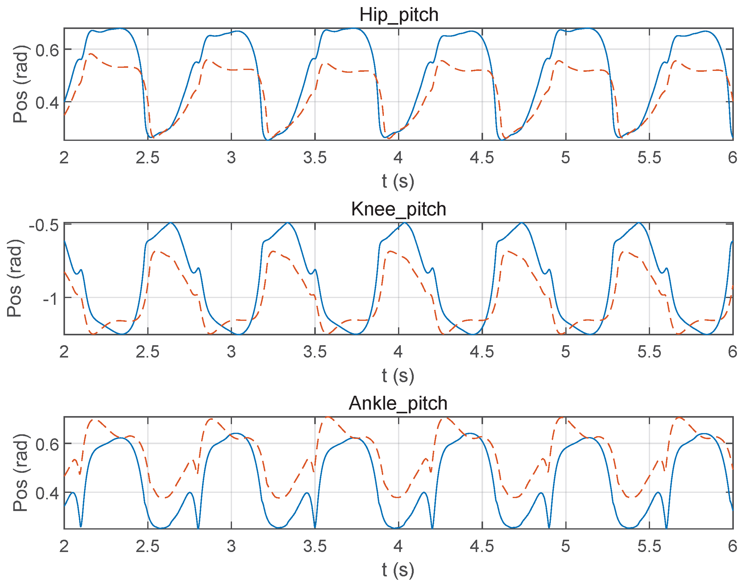
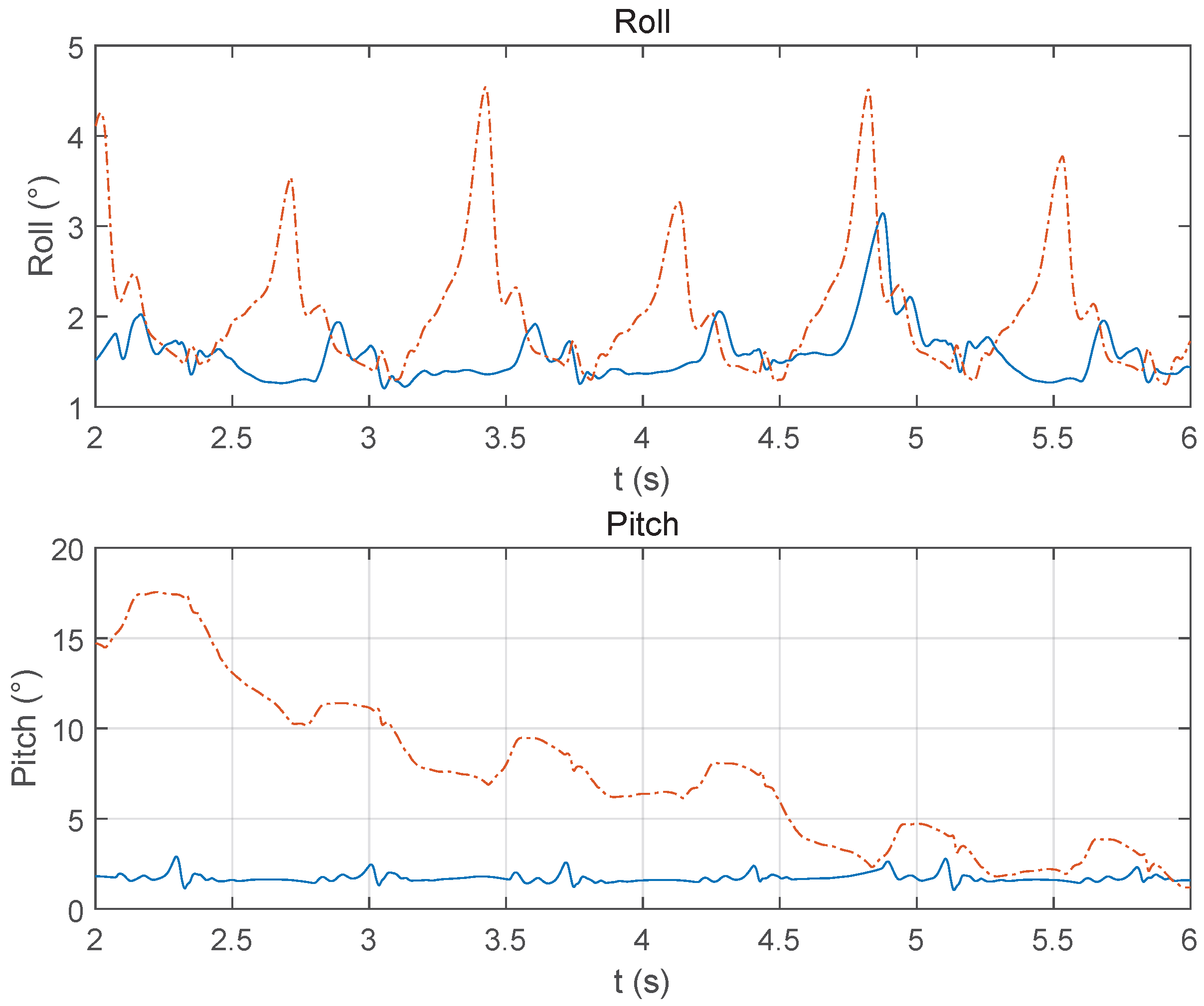
3.2. Dynamic Torque Limit vs. Static Limit

To verify whether the proposed velocity-dependent dynamic power limit strategy offers better actuator protection compared to traditional static constraints while maintaining or even enhancing jumping performance. This study designs a comparative experiment—dynamic torque limit vs. static limit. Three control strategies are tested: (1) Static limit, which imposes fixed torque bounds on joint outputs; and (2) ours, which constructs a dynamic torque bound based on joint velocity and maps it to motor space for action clipping. Evaluation metrics include the proportion of torque outputs exceeding safe bounds and the maximum instantaneous joint power during jumping. This experiment aims to assess whether the dynamic boundary can adaptively adjust with respect to joint speed, thereby ensuring actuator safety without compromising—if not improving—the control performance and stability of dynamic jumping.
The proposed RL control strategy, based on dynamic torque boundary constraints and error-compensation modeling, demonstrates superior performance in comparative experiments. Specifically, the method maintains jump amplitude while effectively regulating joint torque output, thereby reducing the risk of system overload and enhancing both control stability and physical feasibility of the policy. The experimental results are shown in Figure 10, Figure 11, Figure 12, Figure 13 and Figure 14, where the blue solid lines represent the control performance achieved using the proposed method with dynamic torque limiting, while the orange dashed lines correspond to the baseline strategy employing fixed peak torque limits. Experimental results show that, compared to traditional static constraint strategies, the proposed approach achieves better performance in terms of jump height, control smoothness, actuator safety, and postural stability. This provides a reliable solution for deploying RL strategies in high-dynamic tasks.

4. Discussion

This paper presents a RL framework for jumping control that incorporates physical consistency constraints, addressing the challenges posed by actuator torque limitations and structural complexity in tendon-driven bipedal robots performing highly dynamic jumping tasks. By constructing a linear mapping model from joint space to motor space, deriving a dynamic torque boundary expression, and designing a power-aware reward function, the proposed approach significantly enhances the physical feasibility and deployability of learned control policies.
Compared with most existing RL studies, the primary distinction of this work lies in its systematic integration of actuator constraints and structural characteristics into the policy-learning process. In previous works, such as Kumar et al. [29] and Gehring et al. [30], improvements were made in policy generalization and trajectory tracking through fast adaptation modules and optimized control strategies. However, these methods generally did not model actuator torque or power constraints during training, making their policies vulnerable to producing infeasible actions in highly dynamic, non-periodic tasks like jumping. Similarly, while Kim et al. [31] considered power constraints or employed model-guided mechanisms at the policy execution stage to improve stability, most approaches still lacked systematic modeling of actuator limitations during training, leading to control outputs that violate physical feasibility under high-power conditions, thus undermining deployment safety and reliability. In contrast, this work embeds a differentiable motor torque-speed constraint directly into the learning process, enabling the policy to implicitly comply with real-system limitations while optimizing performance, thereby avoiding the need for post hoc clipping or corrections at deployment time.
Moreover, by introducing a torque error-compensation mechanism, the proposed framework significantly improves the fidelity of the simulation environment in approximating real hardware behavior, further mitigating the sim-to-real gap. Hardware experiments demonstrate that the learned policy not only achieves greater jumping height and enhanced stability, but also ensures that the actuators consistently operate within safe power ranges throughout the task, validating the engineering applicability of this approach in high-dynamic scenarios.
While our proposed framework demonstrates promising performance in tendon-driven bipedal jumping, several limitations remain to be addressed. First, the torque transmission model assumes ideal pulley behavior and omits mechanical non-idealities such as friction, hysteresis, and backlash, which may impact performance during prolonged use. Extending the model to include these effects could improve simulation realism and actuator safety. Second, our dynamic torque boundary is primarily defined as a function of joint velocity. However, in practice, actuator limitations are also influenced by factors such as temperature, current saturation, and mechanical wear. Incorporating these variables could enhance long-term robustness. Third, although our framework improves sim-to-real transfer, it has not yet been tested under unpredictable environmental conditions, such as varying terrain or external disturbances. Real-world deployment under such conditions will be a focus of future work. Fourth, our current analysis focuses only on the lower limb joints; integrating full-body dynamics, such as trunk and arm motion, could further improve jump efficiency and stability. Fifth, while the framework is tailored for tendon-driven robots, its modular structure allows for adaptation to other robotic systems by recalibrating the torque mapping and constraint models. Lastly, we acknowledge the absence of quantitative comparisons with prior RL frameworks. Although we qualitatively position our approach relative to existing work (e.g., torque modeling, safety handling), future studies will aim to provide direct metric-based comparisons when compatible baselines are available.
In summary, this work provides a theoretically sound and practically viable solution for deploying RL-based controllers in high-power, structurally complex robotic systems. Although the framework proposed in this study is specifically designed for the jumping task, its foundation in physical consistency and modular structure makes it readily extensible to other high-dynamic behaviors such as running and fall recovery. The dynamic torque boundary model is derived from general actuator power constraints and depends primarily on joint velocity and motor characteristics, which are also critical in other explosive tasks. Similarly, the tendon-driven torque coupling model, while tailored to the current hardware, provides a structured formulation that can be transferred to other tasks where multi-joint coordination is critical. In future work, we plan to validate the applicability of our method to these additional behaviors, further demonstrating its generalizability across dynamic scenarios. For non-tendon-driven systems, such as those using rigid gear transmissions or direct-drive actuators, the torque transmission model must be adapted or simplified to reflect the system’s kinematic and actuation properties. While the tendon-specific coupling structure may no longer be present, similar inter-joint dynamics—due to mechanical constraints or payload interactions—can still be captured through appropriately designed Jacobian-like mappings. The power-aware boundary and reward formulation, however, remains applicable, as actuator safety limits and velocity-dependent torque constraints are fundamental across most robotic systems.

5. Conclusions

This paper addresses the challenges of actuator constraints and structural complexity in high-power bipedal jumping control by proposing a RL framework integrated with physical consistency constraints. The method systematically incorporates joint torque coupling modeling for tendon-driven mechanism and a velocity-dependent dynamic torque boundary mechanism into the policy training process, effectively enhancing the physical feasibility and deployment reliability of the learned control strategy. By establishing a linear mapping from joint space to motor space, the proposed approach accurately captures the torque coupling effects inherent in tendon-driven mechanism, resolving the difficulties of multi-joint coordination. At the same time, a dynamically adjustable torque boundary model based on joint velocity is constructed to reflect actuator power limitations, and is embedded into the reward function. This enables the learning policy to implicitly perceive and respect physical constraints during training. Real-world experimental results demonstrate that the proposed method ensures actuator safety and achieves stable and feasible jumping performance without the need for online adaptation, highlighting its practical deployability. In conclusion, the proposed control framework lays a solid foundation for the practical deployment of RL in high-dynamic bipedal robots and opens up new research directions and technical pathways for control strategy design under complex actuation structures.

Author Contributions

Conceptualization, Y.Z. and Q.L.; methodology, Y.Z., Q.L. and X.M.; software, Y.Z., X.J. and X.M.; validation, Y.Z., J.T. and X.J.; formal analysis, Y.Z.; investigation, X.M. and Q.L.; resources, J.Z. and Q.L.; data curation, Y.Z.; writing—original draft preparation, Y.Z.; writing—review and editing, Y.Z.; visualization, Y.Z.; supervision, Q.L.; project administration, J.Z.; funding acquisition, J.Z. and Q.L. All authors have read and agreed to the published version of the manuscript.

Funding

This research received no external funding.

Data Availability Statement

The original contributions presented in this study are included in the article. Further inquiries can be directed to the corresponding author.

Conflicts of Interest

The authors declare no conflicts of interest.

References

  1. Peng, X.B.; Coumans, E.; Zhang, T.; Lee, T.W.; Tan, J.; Levine, S. Learning agile robotic locomotion skills by imitating animals. arXiv 2020, arXiv:2004.00784. [Google Scholar]
  2. Miki, T.; Lee, J.; Hwangbo, J.; Wellhausen, L.; Koltun, V.; Hutter, M. Learning robust perceptive locomotion for quadrupedal robots in the wild. Sci. Robot. 2022, 7, eabk2822. [Google Scholar] [CrossRef]
  3. Hwangbo, J.; Lee, J.; Dosovitskiy, A.; Bellicoso, D.; Tsounis, V.; Koltun, V.; Hutter, M. Learning agile and dynamic motor skills for legged robots. Sci. Robot. 2019, 4, eaau5872. [Google Scholar] [CrossRef]
  4. Li, Z.; Peng, X.B.; Abbeel, P.; Levine, S.; Berseth, G.; Sreenath, K. Robust and versatile bipedal jumping control through multi-task reinforcement learning. arXiv 2023, arXiv:2302.09450. [Google Scholar]
  5. Xiong, X.; Ames, A.D. Bipedal Hopping: Reduced-Order Model Embedding via Optimization-Based Control. In Proceedings of the 2018 IEEE/RSJ International Conference on Intelligent Robots and Systems (IROS), Madrid, Spain, 1–5 October 2018; pp. 3821–3828. [Google Scholar] [CrossRef]
  6. Lee, J.; Hwangbo, J.; Wellhausen, L.; Koltun, V.; Hutter, M. Learning quadrupedal locomotion over challenging terrain. Sci. Robot. 2020, 5, eabc5986. [Google Scholar] [CrossRef] [PubMed]
  7. Florence, P.; Lynch, C.; Zeng, A.; Ramirez, O.A.; Wahid, A.; Downs, L.; Wong, A.; Lee, J.; Mordatch, I.; Tompson, J. Implicit behavioral cloning. In Proceedings of the Conference on Robot Learning, Auckland, New Zealand, 14–18 December 2022; pp. 158–168. [Google Scholar]
  8. Rajeswaran, A.; Kumar, V.; Gupta, A.; Vezzani, G.; Schulman, J.; Todorov, E.; Levine, S. Learning Complex Dexterous Manipulation with Deep Reinforcement Learning and Demonstrations. In Proceedings of the 14th Conference on Robotics: Science and Systems XIV, Pittsburgh, PA, USA, 26–30 June 2018. [Google Scholar]
  9. Peng, X.B.; Andrychowicz, M.; Zaremba, W.; Abbeel, P. Sim-to-Real Transfer of Robotic Control with Dynamics Randomization. In Proceedings of the 2018 IEEE International Conference on Robotics and Automation (ICRA), Brisbane, Australia, 21–25 May 2018; pp. 3803–3810. [Google Scholar] [CrossRef]
  10. Yu, T.; Quillen, D.; He, Z.; Julian, R.; Narayan, A.; Shively, H.; Bellathur, A.; Hausman, K.; Finn, C.; Levine, S. Meta-World: A Benchmark and Evaluation for Multi-Task and Meta Reinforcement Learning. arXiv 2021, arXiv:1910.10897. [Google Scholar]
  11. Xie, A.; Singh, A.; Levine, S.; Abbeel, P. Dynamics-Aware Embedding for Meta-Reinforcement Learning. In Proceedings of the 37th International Conference on Machine Learning, Virtual, 13–18 July 2020; Volume 119, pp. 10534–10544. [Google Scholar]
  12. Haarnoja, T.; Zhou, A.; Abbeel, P.; Levine, S. Soft Actor-Critic: Off-Policy Maximum Entropy Deep Reinforcement Learning with a Stochastic Actor. arXiv 2018, arXiv:1801.01290. [Google Scholar]
  13. Bellegarda, G.; Nguyen, C.; Nguyen, Q. Robust quadruped jumping via deep reinforcement learning. Robot. Auton. Syst. 2024, 182, 104799. [Google Scholar] [CrossRef]
  14. Zhang, C.; Zou, W.; Cheng, N.; Zhang, S. Towards Jumping Skill Learning by Target-guided Policy Optimization for Quadruped Robots. Mach. Intell. Res. 2024, 21, 1162–1177. [Google Scholar] [CrossRef]
  15. Atanassov, V.; Ding, J.; Kober, J.; Havoutis, I.; Santina, C. Curriculum-Based Reinforcement Learning for Quadrupedal Jumping: A Reference-free Design. arXiv 2024, arXiv:2401.16337. [Google Scholar] [CrossRef]
  16. Zhu, W.; Rosendo, A. PSTO: Learning energy-efficient locomotion for quadruped robots. Machines 2022, 10, 185. [Google Scholar] [CrossRef]
  17. Yan, Z.; Ji, H.; Chang, Q. Energy consumption minimization of quadruped robot based on reinforcement learning of DDPG algorithm. Actuators 2024, 13, 18. [Google Scholar] [CrossRef]
  18. Chen, Z.; Hou, Y.; Huang, R.; Cheng, Q. Neural network compensator-based robust iterative learning control scheme for mobile robots nonlinear systems with disturbances and uncertain parameters. Appl. Math. Comput. 2024, 469, 128549. [Google Scholar] [CrossRef]
  19. Luo, R.; Hu, Z.; Liu, M.; Du, L.; Bao, S.; Yuan, J. Adaptive Neural Computed Torque Control for Robot Joints With Asymmetric Friction Model. IEEE Robot. Autom. Lett. 2025, 10, 732–739. [Google Scholar] [CrossRef]
  20. Zhang, Y.; Zhang, W.; Yang, J.; Pu, W. Bioinspired soft robotic fingers with sequential motion based on tendon-driven mechanisms. Soft Robot. 2022, 9, 531–541. [Google Scholar] [CrossRef]
  21. Choi, J.; Lee, D.Y.; Eo, J.H.; Park, Y.J.; Cho, K.J. Tendon-driven jamming mechanism for configurable variable stiffness. Soft Robot. 2021, 8, 109–118. [Google Scholar] [CrossRef]
  22. Tang, J.; Mou, H.; Hou, Y.; Zhu, Y.; Liu, J.; Zhang, J. A Low-Inertia and High-Stiffness Cable-Driven Biped Robot: Design, Modeling, and Control. Mathematics 2024, 12, 559. [Google Scholar] [CrossRef]
  23. Ko, D.; Kim, J.; Chung, W.K. Ensuring Joint Constraints of Torque-Controlled Robot Manipulators under Bounded Jerk. In Proceedings of the 2024 IEEE/RSJ International Conference on Intelligent Robots and Systems (IROS), Abu Dhabi, United Arab Emirates, 14–18 October 2024; pp. 11954–11961. [Google Scholar]
  24. Liu, X.; Sun, Y.; Wen, S.; Cao, K.; Qi, Q.; Zhang, X.; Shen, H.; Chen, G.; Xu, J.; Ji, A. Development of wheel-legged biped robots: A review. J. Bionic Eng. 2024, 21, 607–634. [Google Scholar] [CrossRef]
  25. Dahl, R.A. The concept of power. Behav. Sci. 1957, 2, 201–215. [Google Scholar] [CrossRef]
  26. Thompson, J.O. Hooke’s law. Science 1926, 64, 298–299. [Google Scholar] [CrossRef]
  27. Kaelbling, L.P.; Littman, M.L.; Moore, A.W. Reinforcement learning: A survey. J. Artif. Intell. Res. 1996, 4, 237–285. [Google Scholar] [CrossRef]
  28. Szepesvári, C. Algorithms for Reinforcement Learning; Springer Nature: Cham, Switzerland, 2022. [Google Scholar]
  29. Kumar, A.; Fu, K.; Večerík, M.; Handa, A.; Bai, Y.C.; Zhang, J.T.; Kalakrishnan, M.; Levine, S. RMA: Rapid Motor Adaptation for Legged Robots. In Proceedings of the Robotics: Science and Systems (RSS), Virtual, 12–16 July 2021. [Google Scholar]
  30. Gehring, C.; Coros, S.; Hwangbo, J.; Siegwart, R.; Hutter, M. Practice makes perfect: Learning to balance in a day. In Proceedings of the International Conference on Intelligent Robots and Systems (IROS), Daejeon, Republic of Korea, 9–14 October 2016; pp. 2639–2644. [Google Scholar]
  31. Kim, S.; Lee, J.; Hwangbo, J.; Hutter, M. Domain randomization and curriculum learning for robust locomotion policies. In Proceedings of the Conference on Robot Learning, London, UK, 8–11 November 2021; pp. 164–180. [Google Scholar]
Figure 1. A RL-based control framework for jumping of hybrid tendon-driven bipedal robots. This figure illustrates a RL framework for controlling the jumping motion of a hybrid tendon-driven bipedal robot. The framework explicitly incorporates motor torque constraints and joint torque error-compensation mechanisms. Through torque transmission modeling, error estimation, joint torque boundary computation, and reward function design, it establishes a control pipeline with strong physical feasibility and high jumping stability.
Mathematics 13 02466 g001
Figure 2. Robot-leg structure diagram, which includes the range of motion of the hip, knee, and ankle joints, as well as the drive mode and maximum torque speed parameters of each motor in the joint. The serial number and component correspond by color.
Mathematics 13 02466 g002
Figure 3. This figure illustrates the error-propagation mechanism in the hybrid tendon-driven mechanism for both the knee and ankle joints. It consists of two parts: the left section shows the knee joint’s error-propagation process, where output errors result from both motor position deviations and tendon elastic deformations; the right section depicts the ankle joint’s error propagation, further revealing how the motor’s driving force is transmitted through the knee pulley to the ankle pulley in a multi-stage drive system, and how errors accumulate and propagate along this path. Key structural parameters, error terms, and their corresponding equations are annotated, providing a clear visual representation of the error sources and propagation paths within the system.
Mathematics 13 02466 g003
Figure 4. The overall process of the RL reward function is illustrated. First, a torque coupling mapping under the tendon-driven mechanism is established. Then, a dynamic joint torque bound related to joint velocity is constructed and mapped to the motor space. Finally, a clipping mechanism is applied to constrain the action output, and corresponding penalty terms are incorporated into the reward function, thereby improving the physical feasibility and actuator safety of the learned policy.
Mathematics 13 02466 g004
Figure 5. Comparison of joint motion trajectories. This figure shows the joint motion trajectories of the hip, knee, and ankle joints under two control methods. It can be seen that the joint trajectories controlled by torque errors and the motor–joint coupling relationship are smoother, indicating higher coordination and stability. This verifies that the strategy of incorporating coupling modeling and torque errors helps improve multi-joint coordination control and jumping stability.
Mathematics 13 02466 g005
Figure 6. Comparison of joint velocity. This figure shows the joint velocities (dq) of the hip, knee, and ankle joints over time under two control methods. The comparison shows that the joint velocities controlled with torque errors and coupling modeling are slightly higher, indicating a higher speed response during the control process.
Mathematics 13 02466 g006
Figure 7. Comparison of joint torque. Joint torque trajectories for hip, knee, and ankle pitch joints. The proposed method effectively reduces torque overshoots and better respects physical constraints, enhancing actuator safety and policy robustness.
Mathematics 13 02466 g007
Figure 8. Comparison of roll and pitch angles during jumping. The proposed method results in smaller posture deviations, confirming better stabilization and enhanced resistance to disturbances.
Mathematics 13 02466 g008
Figure 9. Comparison of robot COM height and feet height. This figure shows the changes in the robot’s COM height and feet height over time under two control methods. The comparison demonstrates that incorporating coupling modeling and torque error-compensation results in higher COM peaks and more consistent foot clearance, confirming enhanced jumping power and improved motion repeatability.
Mathematics 13 02466 g009
Figure 10. Three-joint position trajectories (hip, knee, ankle) during continuous jumping. The proposed method (blue solid line) produces higher joint mobility and smoother motion cycles than the static-limit baseline (red dashed line), enabling stronger and more coordinated jumping behavior.
Mathematics 13 02466 g010
Figure 11. Joint velocity profiles for hip, knee, and ankle joints. Compared to the baseline, the proposed strategy achieves sharper yet more consistent velocity peaks with less jitter, reflecting precise control over joint dynamics and effective suppression of oscillations.
Mathematics 13 02466 g011
Figure 12. Joint torque outputs under different control strategies. The proposed method keeps torque within motor-safe bounds throughout the motion, avoiding the clipping and overshoot issues seen in static-limit control, thereby ensuring actuator safety and torque compliance.
Mathematics 13 02466 g012
Figure 13. Body orientation in roll and pitch during jumping. The proposed controller effectively stabilizes robot posture, especially during landing, with significantly reduced oscillation amplitudes, ensuring improved robustness and balance.
Mathematics 13 02466 g013
Figure 14. Vertical trajectories of COM and feet during jumping. The proposed method enables greater jump height and consistent ground clearance, confirming enhanced jump power and repeatability across motion cycles.
Mathematics 13 02466 g014
Disclaimer/Publisher’s Note: The statements, opinions and data contained in all publications are solely those of the individual author(s) and contributor(s) and not of MDPI and/or the editor(s). MDPI and/or the editor(s) disclaim responsibility for any injury to people or property resulting from any ideas, methods, instructions or products referred to in the content.

