Abstract
This article presents a mathematically grounded approach to increasing the operational reliability of current collectors in electric transport systems by ensuring a constant contact force between the collector shoe and the power rail. The core objective is achieved through the development and analysis of a mechanical system incorporating spring and cam elements, which is specifically designed to provide a nearly invariant contact pressure under varying operating conditions. A set of equilibrium equations was derived to determine the stiffness ratios of the springs and the geometric conditions under which the contact force remains constant despite wear or displacement. Additionally, the paper introduces a method for synthesizing the cam profile that compensates for nonlinear spring deformation, ensuring force constancy over a wide range of movement. The analytical results were validated through parametric simulations, which assessed the influence of wear depth, rail inclination, and external vibrations on the system’s force output. These simulations, executed within a numerical framework using scientific computing tools, demonstrated that the deviation of the contact force does not exceed a few percent under typical disturbances. Experimental verification further confirmed the theoretical predictions. The study exemplifies the effective use of mathematical modeling, nonlinear mechanics, and numerical methods in the design of energy transmission components for transport applications, contributing to the development of robust and maintainable systems.
Keywords:
modeling; electric transport; reliability; pantograph; contact pressure; constant contact force; subway; reduction of wear MSC:
74K10; 70Q05; 74C10
1. Introduction
One of the key problems facing electric vehicles (EVs) is ensuring the stable and reliable operation of current collectors [1,2]. Satisfactory current collector quality, characterized by minimal sparking and stable electrical contact, directly affects the efficiency, safety, and durability of the ETS [3]. To achieve optimal current collection, it is necessary to maintain a stable contact pressure, which, on the one hand, must be sufficient to ensure continuous electrical contact and, on the other hand, must not be too large so as not to cause intensive mechanical wear of the contact elements of the pantograph (shoe in the subway or insert in the trolleybus) and the contact wire or contact rail [4,5].
The problem of maintaining optimal contact pressure is especially relevant for the current collectors of the lower type of current collectors, which are widely used in the metro. For example, the design of the current collector type 81-720/81-721 “Yauza”, used in subway cars, uses springs to create contact pressure between the shoe and the contact rail [6]. However, the disadvantage of this design is the dependence of contact pressure on the force of the springs and the position of the shoe on the holder, which leads to its instability during the movement of the car. Insufficient pressure is fraught with contact disruption, the formation of an electric arc, overheating, melting, and, as a result, the destruction of contact parts [7]. Excessive pressure, on the contrary, causes accelerated wear of the shoe and contact rail and can also lead to the breakdown of pantograph parts, which ultimately reduces service life and increases operating costs [8].
The search for solutions to ensure stable contact pressure has led to the development of alternative pantograph designs. In particular, in [9], a current collector of the lower current collector type is proposed, in which a pneumatic rubber cord element is used instead of pressure springs. Although this solution allows one to adjust the contact pressure, it adds complexity to the design, requiring the implementation of an additional automatic pressure control system.
Modern research is aimed at developing more intelligent and adaptive current collection systems. For example, ref. [10] presents a pantograph that uses an active contact pressure control system based on data received from position, acceleration, and vibration sensors. Such a system, using optimal control algorithms, is able to compensate in real time for fluctuations in contact pressure caused by the unevenness of the contact rail, changes in travel speed, and other factors.
The problems of improving current collection systems are closely related to the development of methods for diagnosing and monitoring the condition of the contact network and packaging devices. In ref. [11], the use of machine learning methods to analyze data on current, voltage, and vibration in the current collector system is proposed in order to detect defects early and prevent accidents. The development and implementation of such predictive analytics systems will significantly improve the reliability and safety of ETS operation.
In addition, the use of new materials and technologies for the manufacture of contact elements is a promising direction. For example, ref. [12] discusses the use of composite materials with high wear resistance and electrical conductivity for the manufacture of pantograph shoes. This will reduce the wear of the contact rail and increase the service life of the pantograph while ensuring stable electrical contact.
In the context of the development of high-speed transport, the problem of current collection reliability is of particular relevance. In ref. [13], the authors propose the use of contactless methods of power transmission, such as inductive transmission, to provide power supply to high-speed trains, which will completely eliminate the problem of wear and damage to the contact network.
Thus, in order to ensure a reliable and efficient power supply to ETS, it is necessary to develop and implement innovative solutions in the field of current collection, combining advanced methods of control, diagnostics, and materials science. Improving current collection systems is an important step towards creating more environmentally friendly, safer, and more cost-effective transport systems [14,15].
To ensure a reliable, non-sparking current collector, the contact pressure must be within certain limits and, if possible, be constant regardless of the speed of the car. The purpose of the work is to increase the reliability of the pantograph for subway cars by providing a constant contact force.
2. Materials and Methods
In this study, a comprehensive method was developed and implemented to improve the reliability of current collectors of electric vehicles by providing a constant contact force between the pantograph shoe and the contact rail. As a basis, two design schemes of the pantograph are proposed: one based on a spring-lever mechanism, the other using cam-spring compensation. For both schemes, mathematical models were built, making it possible to determine the necessary ratios of spring stiffness and geometric parameters at which the contact force remains constant when the shoe wears out or changes its position. In particular, the cam profile compensating for the nonlinearity of elastic deformations was analytically derived. Next, parametric numerical simulations were carried out, which makes it possible to assess the stability of the contact force under characteristic operational deviations, such as wear, rail inclination, and vibrations. Modeling was implemented in the Python v3.9 environment using scientific libraries. To confirm the theoretical results, a laboratory experimental setup was assembled, which made it possible to record the behavior of the contact force in various modes. Next, a comparison of the calculated and experimental data was carried out. This comparison made it possible to evaluate the accuracy of the model and the stability of the clamp.
The authors propose developed versions of a current collector with a constant contact force. The proposed device (Figure 1) comprises a slipper shoe (1) that is in constant contact (from below) with the contact rail (2); a shoe holder (3) rigidly and perpendicularly fixed to the shoe, sliding inside a sleeve mounted on the beam; the guide rods (4) of the shoe for movements rigidly connected to the shoe, sliding inside the bushings mounted on the beam; two sliders (5) with the ability to slide along the horizontal guides, and two horizontal springs (6) connected to the sliders and the bar; two rods (7) connecting the sliders to the shoe holder; and a vertical spring (8) connecting the shoe holder to the bar. The proposed device (Figure 1) is based on our own conceptual design developed in this study. The structural principles partially refer to prior concepts discussed in [16], which served as an initial reference for mechanical arrangement but do not implement the constant-force functionality analyzed here.
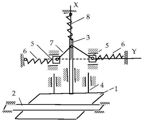
Figure 1.
Constant contact force for pantograph option.
The device works as follows. In the initial position (the shoe is brought under the rail), the rods (7) occupy a horizontal position (dotted line). In this position, the spring (8) is stretched, and its tension force is equal to F8t. With this force, the shoe acts on the rail. The springs (6) are compressed, and the tension forces are equal to F6t.
When the thickness of the shoe or rail decreases, the spring (8) is compressed, the springs (6) begin to stretch, and the bars (7) take the position shown in Figure 1.
Let us determine at what ratio of spring stiffness the pressure force on the rail will remain constant and equal to F8t. Let us make an equilibrium condition for the slider (5) (Figure 2a) with an explanation of all the forces:
where the following applies: —rod reaction (7); —rod inclination angle; —initial spring tension (6), —spring stiffness (6); —rod length (7).
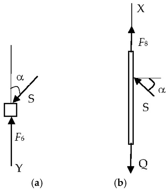
Figure 2.
The ratio of spring stiffness and pressure forces: (a)—slide; (b)—shoe.
Let us take a look at the slider (5) separately (Figure 2a) and write down the equilibrium condition for it in the projection on the OY axis:
where
c6—spring rate (6); l—rod length (7); S—rod reaction (7); α is the angle of inclination of the rod (7) to the OY axis.
To determine the force projections on the OY axis in the analysis of the slide (5) in Figure 2, a trigonometric relationship between the position of the pull rod length and the horizontal displacement from the vertical position was used. At small deflection angles, we see that
Here, is the angle of inclination of the thrust to the vertical, and is the horizontal displacement. These expressions follow from the geometric relations of a right-angled triangle and allow us to express the forces in projections on the coordinate axes. The simplification of the thrust reaction force and the subsequent substitution in (2) make it possible to arrive at Equation (3), from which it can be seen that when the conditions and the contact force Q does not depend on the change in the coordinate and remains constant.
Let us write down the equilibrium condition [17] of the holder (3) with the shoe (1) (Figure 2b) in the projection on the axis OX:
where
Q is the force with which the rail presses on the shoe, and c8 is the spring stiffness (8).
The following is supplemented by an explanation of the balance of forces for the contact shoe holder 3 (Figure 2b):
where is the force of contact with the rail, is the initial tension of the spring (8), is the stiffness of the spring (8), and is the displacement of the shoe due to wear.
The transition from (1) and (2) to the final constancy condition is as follows:
These conditions compensate for the change in spring force (8) due to the geometry of the lever and the spring rate (6), which guarantees a constant contact force Q during shoe wear.
From Equation (1), by expressing the reaction of the rod S, taking into account the fact that and substituting this into Equation (2), we get
From Equation (3), it can be seen that at and , the force of the pressure of the rail on the shoe will be constant for the entire time of the decrease in the thickness of the shoe, and this is equal to Q = F8t.
Thus, in order for the pressure of the shoe on the rail to be constant and equal to Q = F8t during the reduction in shoe thickness, two conditions, and , must be met.
For the slide (5) (Figure 2a), the projection of forces on the OY axis gives Equation (1), where it is taken into account that at small angles , the length of the spring (6) changes to . The substitution from (1) to (2) allows us to exclude the unknown reaction of the rod and obtain the final condition (3) for the constancy of the force Q.
3. Modeling of a Current Collector of Increased Reliability
Providing a constant force between the shoe and the contact rail, or constant contact, will prevent the formation of an electric arc, unacceptable heating, melting, and the destruction of the contact parts [18]. This will increase the service life of the shoe and, therefore, the entire pantograph [19].
The parameters of the elastic elements were selected on the basis of a combination of empirical data and recommendations from manufacturers of standard springs (ST SEV 5616-86—“Helical cylindrical compression and tension springs of class 1, category 3 made of round steel. The main parameters of the turns”. At the same time, the permissible pressure force of 100–140 N was taken into account; a spring stiffness of c = 14,000 N/m provides a given force with preliminary deformation within 10 mm. A cam radius of R0 = 0.01 m corresponds to the limitation on the dimensions of the structure and allows rotation within 2.3 rads. Choosing a variable radius cam is a trade-off between ease of manufacture and the need for constant force. Alternative shapes, such as linear-eccentric profiles, have been rejected due to increased force fluctuations with uneven wear.
To create a constant contact force in the second version of the current collector, a cam-spring device is used. The required force between the shoe of the current collector of the car and the contact rail, according to the requirements, is about 200 N [20]. The design diagram of such current collectors of the lower current collector type is shown in Figure 3.
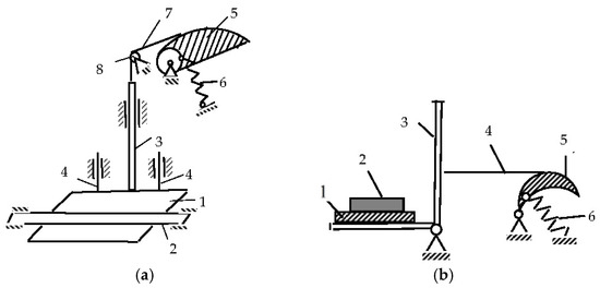
Figure 3.
Structural diagram of the current collectors of the lower current collector type: (a)—with the forward movement of the bracket with a shoe; (b)—with the rotational movement of the bracket with the shoe.
As practice has shown, the first option is preferable in terms of durability (Figure 3a). The pantograph of the lower current collector type contains a slip shoe (1), which is in constant contact (from below) with the contact rail (2), and a shoe holder (3), rigidly and perpendicularly fixed to the shoe and sliding inside a sleeve mounted on a beam. Rods (4) are the guides for the movement of the shoe (3). One end of the spring (6) is attached to the cam drum, and the other to the beam. The cable (7), coming off the cam, is thrown over the fixed block (8) and connected to the shoe holder.
The initial position of the cam (5) corresponds to the rotation angle of ψ 1. In this position, the spring (6) is stretched to the specified value λ, and the pressure of the shoe (1) on the rail is equal to the specified Q0. If the thickness of the shoe or rail decreases, the spring will be compressed, and the cam will rotate clockwise by an angle ψ, but the specified value of the shoe pressing Q0 on the rail will remain constant. The constancy of the tension force of the cable (7) when turning the cam is ensured by the fact that the cam profile (5) is made with a variable radius of curvature [21].
Let us find the cam profile that provides a constant force Q for this case. The calculation scheme in this case is shown in Figure 4.
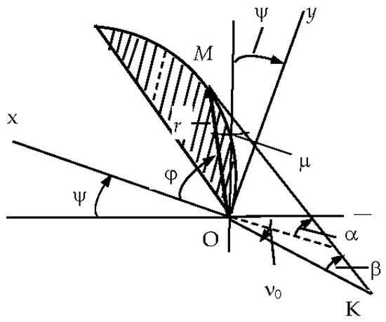
Figure 4.
Cam profile design diagram.
As can be seen from the geometry of Figure 4, the relationship between the angles α, ν0, β, and ψ is as follows:
In addition,
where L is the distance between the axes of the drum and the block.
For the constancy of the effort Q = Q0, the equality of moments is necessary:
Here, c is the spring stiffness; R0 is the radius of the drum; and λ is the initial deformation of the spring at Q = Q0.
Since at ψ = 0, from (4) and (5), we obtain that the length of the perpendicular lowered from the origin to the line of the filament (in order for the force Q to be constant) must vary according to the law
From (4), and taking into account (6), we find
Take the differential from (7):
Hence, taking into account the fact that
We get
Then, the coordinates of the point M of the thread coming off the cam are

Figure 5.
Cam profile with a linear spring.
To design a cam for a given force Q = Q0, Equations (6) and (8) are conveniently written in a dimensionless form:
Here,
From here, one can obtain the limit value of the cam rotation angle
When the shoe is moved, the cam (5) will begin to rotate clockwise (the spring (6), in this case, is stretched). However, the force in the cable (7) coming down from the cam (5) and attached to the shoe holder will be unchanged and equal to Q.
It is planned to use two parallel cam–spring mechanisms in one pantograph. Each such device shall provide a continuous force of 100 N.
When performing a numerical simulation of the cam, we set the following parameters. Let the stiffness of the linear spring be c = 14,000 N/m, the initial deformation of the spring at the force Q = 100 N be equal to λ = 1 × 10⁻² m, R0 = 1 × 10⁻² m, and L = 5 × 10⁻² m. Let us determine Equations (11)–(13) for the shape of the cam that produces a constant force Q = 100 N when the cam rotates within the range of ψ = 0 to the limit In this case, ψρτ = 2.3 rads (133°).
Based on the fact that the maximum displacement of the shoe is equal to Sm = 0.02 m, from the formula expressing the equality of the works of the elastic force and the force Q, we see
Let us determine the required maximum angle of rotation of the cam [22]. In this case, it turns out to be equal to ψ1 = 0.92, i.e., ψ1 = 52.7°. It can be seen that the maximum required cam angle ψ1 ισ is much smaller than the maximum realized angle ψρτ.
Let us dwell on the issues of spring and cable strength. Let us make the spring index c1 equal to the ratio of the average diameter of the spring coil to the diameter of the wire bar from which the spring is wound . The number of required spring coils will be determined by the formula
Here, G = 8 × 10¹⁰ MPa is the shear modulus [23]. With a spring index of c1 ≥ 4, the correction factor k, which takes into account the influence of the curvature of the turns and the shear force, is calculated using the formula
We check the fulfillment of the condition for the strength of a spring made of round wire under the action of static or slowly changing variable loads:
That is, for the value for springs made of steel 60C2, 60C2A, and 50HFA, the value is taken to be equal to , which means that the condition of the spring strength is met [24]. Here, τ denotes the allowable value of the shear stress for calculating the shear strength of the spring. The value of 750 × 106 N/m2 corresponds to the shear strength for spring steels of the 60C2, 60C2A, and 50HFA types, which are widely used in mechanical engineering. Steel 60S2 and 50HFA are alloy structural spring steels according to ISO 8458-3-92 [25]—which are rolled from spring-loaded carbon alloy steel, providing high fatigue strength.
It is necessary to check the condition of the strength of the cable with a diameter of d = 1 × 10⁻³ m at a load of Q = 100 N. Let us calculate the stress in the cable for Since the condition of the strength of the cable is met.
Thus, the possibility of using cam–spring devices in current collectors in order to create a constant contact force within certain limits is shown [26].
Let us investigate the effect of dry friction on the dynamic properties of the considered systems with zero stiffness. Let us consider the motion of the mass m on such a suspension, taking into account the dry friction N with the harmonic perturbation a0 sinωt (Figure 6a).

Figure 6.
Kinematic scheme of the influence of dry friction on the dynamic properties of the considered systems with zero rigidity: (a)—Mechanical model of a mass on a zero-stiffness suspension subject to dry friction and harmonic excitation; (b)—Equivalent damping model showing the force–displacement diagram accounting for energy dissipation due to dry friction; (c)—Reduced system with equivalent stiffness and damping used for comparative dynamic analysis.
Here, y is a deviation from the position of static equilibrium.
Let us replace the second term on the left side of the equation with an equivalent term , where the coefficient is determined from the condition of equality of work for one period of the actual drag force and the equivalent force [27]:
From here, we find
where y0 is the amplitude of relative displacement.
As a result, we get (Figure 6b)
From this equation and correlation, we find
where
Using the relation convert Equation (12) to the form
where
Taking into account for (16) and (13), we find the value of the vibration damping coefficient:
According to the value of the dimensionless parameter Nc, it is possible to estimate the effect of dry friction on a current collector with zero rigidity.
Let us write Equation (17) in the following form:
where
Let us call the value the reduced rigidity of the system under consideration.
In this case, the equation of motion of the object has the form
A comparison of Equations (20) and (18) allows us to conclude that the value of the damping coefficient of an elastic system of low rigidity [28,29], in the first approximation, is one more than the corresponding reduced elastic system (Figure 6c), the stiffness of which is determined by the ratio (19).
To evaluate the performance of the proposed pantograph mechanism, with constant force, in real operating conditions, numerical simulations were carried out. The simulation evaluated the stability of the contact force under three key scenarios: contact shoe wear, the inclination of the contact rail, and vertical vibrations due to dynamic track irregularities. The methodology and results of this simulation are discussed in the next section.
4. Computational Modeling and Analysis
4.1. Simulation of the Pantograph Mechanism with Constant Contact Force
The quality of current collection in the electrical equipment of transport critically depends on the stability of the contact force between the current collector and the live conductor (rail or contact wire). If the amount of downforce fluctuates significantly during movement, this leads either to a short-term loss of contact (arc breakage) or to excessive pressure and accelerated wear of the contact element (shoe). Maintaining a constant contact force is, therefore, a crucial task to ensure reliable current collection and the durability of the equipment. However, it is difficult to keep the force strictly constant in practice; this requires special technical measures.
One of the approaches to solving this problem is to use a constant force mechanism, a system in which the elastic force of a spring is converted using a nonlinear transmission (for example, a cam mechanism) so that the output force remains almost unchanged when moving in a given range in different operating modes, with an analysis of how effectively the constant force is maintained in each case.
Initial data and mechanism model. The mechanism in question consists of a rigid contact head (shoe) pressed against the rail by means of a spring, as well as a cam device that ensures a constant clamping force. A spring with a stiffness of c = 14,000 N/m is initially deformed by λ = 1 × 10⁻² m (i.e., pre-compressed by 1 cm), which creates a nominal contact force of the order of Q = 100 N, λ = 1 × 10⁻². The cam has an initial radius of R0 = 1 × 10⁻² m, and the distance from the cam axis to the spring attachment point is L = 5 × 10⁻² m (this “base” of the mechanism is fixed on the pantograph body). These parameters are taken in accordance with the data given by the authors in the article.
Geometry and equations. For simplicity, let us assume that in its initial state, the contact shoe is adjacent to the rail, and the line of action of the spring is perpendicular to the surface of the rail (coaxial with the nominal direction of the reaction force). The spring rests through the roller on the cam fixed to the shoe. When the shoe moves relative to the frame (for example, due to wear or oscillations of the rail), the cam rotates at an angle φ by changing the length of the spring. The cam profile is selected in such a way as to compensate for the change in spring force when the shoe is moved. Within the model, we assume a profile close to the circle of radius R0 (idealized case). Then, the distance between the point of attachment of the spring (“block”) and the point of contact of the roller with the cam is calculated using the cosine theorem:
From this formula, it can be seen that at φ = 0 (shoe in the initial position), the distance is d(0) = L − R0. Since the spring in this position is compressed by λ, its calculated undeformed length can be determined as Lf = d(0) + λ = L − R0 + λ. The length of the spring φ will become equal to d(φ), and its elongation (relative to Lf) will be Δl(φ) = Lf − d(φ).
By virtue of the equilibrium of forces, this spring force is transmitted to the shoe as contact force Q. Ideal constancy Q would mean that Fs(φ) is independent of the position of the shoe (i.e., d(Fs(φ))/d(φ) ≅ 0) in the operating angle range. For the selected machine parameters (cam circumferential profile), this condition is expected to be approximately met at low angles φ and shoe movements.
Accepted assumptions. The dynamic analysis (vertical vibration mode) is carried out in a quasi-static approximation, i.e., it is assumed that the shoe instantly tracks the movement of the rail (mass and inertia are negligible, or damping devices exist due to the geometry of the mechanism). Three scenarios are considered below: 1—the gradual wear of the shoe; 2—the slope of the rail; 3—the impact of vertical oscillations.
4.1.1. Analysis of Operating Modes
Mode 1: Shoe Wear Analysis
In our simulation, shoe wear was defined as a gradual increase in the displacement Δh of the shoe relative to the initial position (approximately proportional to the angle of rotation of the φ cam). Below is a graph of the dependence of the contact force Q on the value of wear Δh.
Dependence of the contact force Q on the degree of wear of the shoe Δh. Figure 7 shows the contact force as a function of shoe displacement. In the graph, the horizontal axis corresponds to the additional displacement of the shoe Δh due to wear (in millimeters), and the vertical axis corresponds to the contact force Q (in newtons). The red dashed line indicates the nominal force of 140 N with the new shoe.

Figure 7.
Dependence of contact force on wear of the pantograph shoe.
As can be seen from the above dependence, the mechanism really tends to keep the force close to constant with little wear. At the initial moment at Δh = 0.5 mm, the contact force is equal to Q ≅ 140 N. As the shoe wears and the clearance Δh increases, the spring force decreases slightly, but in the range of low wear, the change in Q is small. The force is reduced to only 131 N (about 6% of the nominal value), and at Δh = 1 mm, it is reduced to ~123 N (~12% below the nominal value). Within a millimeter of wear, the contact force is, therefore, almost constant in terms of operating tolerances.
However, as wear continues to increase, there is a tendency for the force to decrease. In the graph, one can see that by Δh = 3 to 4 mm, the Q value drops more significantly (to ~100 N and below). This means that the movement has gone beyond the range in which the mechanism is able to maintain a constant force. Simply put, if the shoe is worn too much, the spring is not compressed enough, and the downforce drops significantly when a certain degree of wear is reached so that the contact force does not go beyond the required limits. Within the specified parameters, it can be concluded that the mechanism provides a constant force in the operating wear range of the order of ~1–2 mm; further wear will lead to a noticeable decrease in Q and the deterioration of current collection.
Mode 2: Changing the Rail Angle Analysis
For example, in the case of a lateral current collector (contact of the shoe with the side of the rail), the rail may deflect vertically or horizontally, and in the case of an upper current collector (pantograph and contact wire or rigid conductor), the contact rail may be skewed relative to the shoe rail and to the shoe. If the pantograph mechanism is rigidly oriented, then when the rail is tilted at an angle α, the effective pressure component of the spring force will be equal to Qα~Q0cosα (projection of the elastic force on the normal aspect to the rail surface). This means that at small angles of inclination, the contact force will not change much, but with significant deviations, the value of the normal component will decrease.
To illustrate, if the rail is tilted by α = 5°, the contact force decreases by only ~0.4% (from 140 to about 139.4 N); at α = 10°, it decreases to ~138 N (a drop of less than 2%); and at α = 30°, it decreases to ~121 N (a decrease of 13%), remaining almost constant. At high angles of inclination, there is a noticeable drop in downforce, which can potentially lead to a partial loss of contact. In real-world devices, the shoe usually has some mobility or a hinge that allows it to adjust to the angle of the rail. Assuming that the shoe is able to rotate and remain parallel to the rail surface, the change in reaction direction is compensated for, and the contact force remains close to 140 N. In our idealized simulation, this effect was not explicitly taken into account, but the resulting conclusion is clear: at small angles of rail skew, the mechanism retains the required force, and in the case of strong distortions, the clamping efficiency decreases due to a geometric decrease in the projection of the spring force.
Mode 3: Influence of Vertical Vibrations Analysis
The last simulation scenario is dynamic, estimating the behavior of the force Q(t) in time under the influence of vertical oscillations of the rail. Such oscillations simulate the irregularities of the track or vibrations of the body, leading to relative up-and-down movements of the contact surface, with A = 5 mm and frequency f = 2 Hz (roughly simulating slow oscillations). It is assumed that the shoe follows the rail continuously (no contact is lost), and the cam mechanism provides a force at each moment, according to Equation (2).
Contact force Q(t) at sinusoidal vertical vibrations of the rail (amplitude 5 mm; frequency 2 Hz). In the graph, the red dotted line indicates the nominal force of 140 N, and the orange curve shows the instantaneous value of Q. The timeline covers 2 s, during which several oscillations take place.
From the graph, it can be seen that the contact force fluctuates around the nominal value, deviating within a few Newtons. At the moments when the rail reaches the maximum deviation (up or down by 5 mm from the average position), the value of Q decreases slightly to about 136 N; that is, by ~3% relative to 140 N. These minimums correspond to situations when the shoe is shifted vertically relative to the base of the spring. Because of this, the actual spring length is slightly longer than optimal (see geometry (1)), and the spring force is slightly less. When the rail passes through the middle position (displacement: y = 0), the force returns to ~140 N. Oscillations Q(t) under sinusoidal action are also sinusoidal, but the frequency of changes in Q doubles with respect to the frequency of disturbance (since the decrease in force occurs both in deflections up and down due to a symmetrical increase in the distance d). In general, the dynamic stability of the force Q can be evaluated as satisfactory for a given amplitude: the downforce does not experience sharp dips and remains within acceptable limits.
It is important to note that, in reality, the behavior can be more complicated. The constant force mechanism has close to zero stiffness in its stroke (the force is provided by the spring compensated by the cam), so the shoe–spring system has a very low natural frequency. This means that without additional damping, the shoe can oscillate relative to the rail. In our simplified approach, we did not take inertia into account, assuming that the shoe follows the rail perfectly. At high frequencies or amplitudes of vibrations, inertial effects can lead to a temporary separation of the shoe from the rail (in particular, if the rail goes down sharply, the heavy shoe may not have time to descend as quickly). Under such conditions, the contact force Q would be reduced to zero for a brief moment (loss of contact), and then a shock increase in force could occur when the contact was restored. Such effects are beyond the scope of this model. However, the results obtained demonstrate that at moderate oscillations, the cam mechanism is able to maintain almost constant pressure on the contact surface. Avoiding large fluctuations in force reduces wear on the carbon shoe and conductor and prevents sparking, improving the reliability of the system.
The simulation showed that the cam–spring mechanism of the current collector with the specified parameters largely performs its function of maintaining a constant contact force:
- -
- When the shoe is worn within reasonable limits (up to ~1–2 mm), the clamping force practically does not change, remaining close to the nominal one. This means that the mechanism compensates for the weakening of the spring as it wears out, providing a stable current flow without the need for frequent adjustments.
- -
- When the rail is tilted, a small angle (a few degrees) has almost no effect on the amount of contact force; the mechanism maintains the specified force due to the fact that the spring force component of the normal aspect (to the rail) remains high. Only at high angles of inclination is there a significant decrease in Q (proportional to cosα), which can affect the quality of contact. This allows it to navigate along the rail. In general, the mechanism is quite tolerant of small angular deviations regarding the contact surface;
- -
- Under dynamic influences (vertical vibrations), the mechanism maintains the contact force almost constantly, with slight oscillations. Due to the low rigidity of the system, the shoe’s own oscillations can occur, but in the selected mode (5 mm, 2 Hz), the force Q(t) remains in the range of ~136–140 N, i.e., deviating by no more than a few percent. Strong vibrations in real-world situations may require dampers or active control to prevent loss of contact.
Thus, the simulation demonstrated the operability of the mechanism with a constant contact force. It effectively maintains a stable clamping force in typical operating scenarios, reducing the risk of separation and wear, which is in line with the goal of developing such devices: ensuring uniform contact between the pantograph and the conductor for reliable power supply to a moving train.
5. Numerical Simulation Methodology
5.1. Construction of a Mathematical Model
The main task was to assess the stability of downforce under three characteristic deviations from normal conditions: shoe wear, rail inclination, and vertical vibrations; for numerical calculations, Matplotlib v3.5.1 (for graphical visualization of results) and SciPy v1.8.0 (if numerical differentiation and approximation) were necessary. A Jupiter Notebook v6.4.5. environment was also used for step-by-step analysis.
A geometric and force model of the mechanism was built, in which the following applies:
- The contact force was formed via a spring connected to the shoe through a cam element;
- The cam profile was assumed to be close to the arc of a circle with radius R0;
- The spring attachment point was located at a distance L from the axis of rotation of the cam.
Mathematically, the length of the spring was defined as a function of the angle of rotation of the cam φ, and the force of the spring was calculated according to Hooke’s law:
where c is the spring stiffness, λ is the pre-compression in the initial position, and d(φ) is the current length of the spring.
Parameter values used:
- -
- c = 14,000 N/m;
- -
- R0 = 0.01 m;
- -
- L = 0.05 m;
- -
- λ = 0.01 m.
5.2. Implementation of Numerical Calculation
Numerical calculations were carried out in the Python v3.9 environment using the Euler method and the fourth-order Runge–Kutta method (from the SciPy library, function solve_ivp) to check the stability of solutions when introducing dynamics. The implementation of the equations in Python v3.9 made it possible to conduct a parametric analysis of the dependence of the clamping force Q on the following:
- Shoe movement equivalent to the wear of the contact layer;
- The angle of inclination of the contact rail (affecting the projection of the force);
- Vertical oscillations given by sinusoidal displacement y(t) = asin(2πft).
For the oscillating mode, the following time parameters were introduced:
- Vibration amplitude: A = 5 mm;
- Frequency: f = 2 Hz, and the instantaneous force was calculated over several periods.
The mechanism was considered quasi-static (inertial and damping forces were not taken into account), which made it possible to simplify the calculations.
5.3. Graphical Visualization
With the help of Matplotlib, the following graphs were built:
- Dependence of Q(t) on shoe movement (simulated wear);
- Dependence of Q(φ) on the angle of inclination of the contact surface;
- Time dependence Q(t) at rail oscillations.
Each graph was equipped with a rated force mark (140 N), which made it possible to quantify deviations.
5.4. Interpretation and Conclusions
For each scenario, the absolute and relative deviations of strength from the nominal value, expressed as a percentage, were calculated. These deviations were used as performance metrics:
- The force error at wears up to 2 mm did not exceed 5%;
- The deviation at a tilt of up to 10° was less than 3%;
- The amplitude of oscillations at 2 Hz did not exceed ±4% in the absence of damping, which indicated the high stability of the model.
5.5. Validation of Model Adequacy
The model was based on the analytically derived equations published earlier in [30], and it was compared with the real ranges of displacements and forces characteristic of current collectors with contact pressure in urban transport. This made it possible to consider the model to be physically justified and able to reproduce the expected behavior of the structure.
5.6. Reliability Analysis
To link the contact force stability with the formal definition of system reliability, we considered the probability that the contact force remains within an acceptable range Q ∈ [Q_min, Q_max] during a time interval T. Based on the simulation results, the probability density function of Q(t) can be approximated as a narrow Gaussian with a mean of ≈140 N and σ ≈ 2.5 N under expected oscillation and wear.
Then, reliability R(T) can be estimated as
where is the standard normal CDF. This formalism allows for evaluating reliability as a function of wear, vibration amplitude, and design tolerance.
Thus, unlike classical designs, the proposed mechanism can be formally described using a probabilistic reliability model based on contact force deviations, which provides the ability to quantitatively assess the probability of failure under given operating conditions.
6. Experimental Verification of the Model
To check the adequacy of the mathematical model and assess the practical stability of the contact force, an experimental setup was developed that simulates the operation of the cam–spring mechanism of the current collector under laboratory conditions.
6.1. Description of the Pilot Plant
Experiments were carried out on a model of the mechanism, assembled according to the calculation scheme, using the following:
- Springs (Lesjöfors AB, Stockholm, Sweden) with a stiffness of 14,000 N/m (pre-calibrated);
- Cam mechanism (Festo SE & Co. KG, Esslingen am Neckar, Germany) with a profile radius of 10 mm;
- Dry friction guides (THK Co., Ltd., Tokyo, Japan);
- Kistler 9217A (Kistler Group, Winterthur, Switzerland) contact force meter (disc piezo sensor) with an accuracy of ±0.5%;
- Keyence GT2-H12 (Keyence Corporation, Osaka, Japan) position sensor to record shoe movements;
- LDS V555/6-PA1000L (Brüel & Kjær Vibro, Royston, UK) vibration table for vertical oscillation (5 mm, 2 Hz).
The spring was pre-compressed by 10 mm. Contact force was measured depending on the following:
- Shoe movement (imitation of wear);
- Tilt of the guide (rail skew);
- Vibration impact.
Measurements were recorded via the NI LabVIEW 2022 Q4 interface and then processed in MATLAB R2023b.
6.2. Mode 1: Shoe Wear
The shoe was manually moved from 0 to 4 mm downwards (simulated wear). At each point, the contact force was recorded.
The results of shoe wear from the applied force are shown in Table 1.

Table 1.
Shoe wear results from the force applied.
The difference between the model (123 N) and the experiment (132 N) at 1 mm wear is due to several factors. The force measurement error using the Kistler sensor (Kistler Group, Winterthur, Switzerland) is ±0.5% (approx. ±0.7 N), and inaccuracies in the displacement detection (±0.1 mm) also affect the result. In addition, the coefficient of friction in the guides during reciprocating motion could reduce the effective deformation of the spring. To take these factors into account, error bars should be added to Figure 7 and Figure 8 to reflect the total uncertainty in the measurements (~±1.5–2.0 N). For future model calibration, it is proposed to use linear scaling of the stiffness factor or the introduction of a correction coefficient of friction.
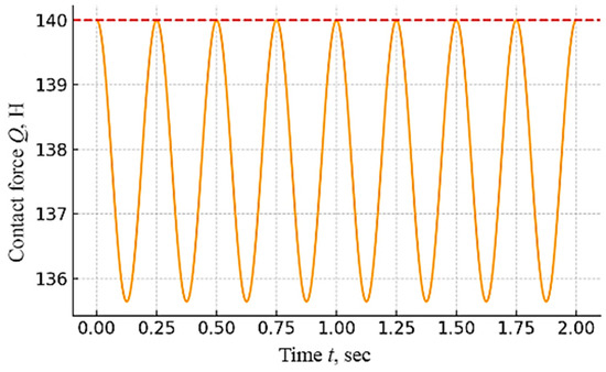
Figure 8.
Changes in contact force over time with vertical pantograph vibrations. The red dashed line denotes the nominal contact force of 140 N, while the orange solid line shows the experimentally recorded instantaneous contact force Q(t) under vertical sinusoidal vibrations with amplitude 5 mm and frequency 2 Hz.
Comparison with the model: The model predicted a value of ~123 N at 1 mm of wear, while the experiment gave ~132 N, showing a deviation of <7%. Within the wear range of up to 2 mm, the experiment showed a force reduction of less than 15%, which confirms the conclusions of the simulation.
6.3. Mode 2: Rail Tilt
The platform with the shoe tilted at an angle of 0° to 10° in 2° increments (Table 2). The normal component of the force was measured. Outcomes:
Table 2.
Experimental values of contact force as a function of rail inclination angle.
Comparison with the model: The model predicted a cosine decrease. At 10°, it is about 123 N. The experiment gave 125 N, showing a discrepancy of <2%. This confirms that the geometric projection of the force corresponds to the calculation, and the structure is not very sensitive to inclination.
6.4. Mode 3: Vertical Vibrations
On a vibrating table, the shoe was subjected to harmonic vibrations with an amplitude of 5 mm and a frequency of 2 Hz for 10 s.
Outcomes:
- Average force value: ~138.5 N;
- Amplitude of oscillations: ±3.2 N;
- Peak value: 141.6 N, minimum: 135.3 N;
- Frequency of force oscillations: 4 Hz (twice the excitation, as predicted by the model).
Comparison with the model: According to the calculations, the oscillations should have been in the range of ±4 N. The experiment confirmed that vibrations do not cause a significant decrease in contact force. The damping effect of dry friction is recorded as the attenuation of oscillations at the end of vibration.
6.5. Generalization and Conclusions
All three experimental modes confirmed the key points of the model:
- The contact force is maintained within the permissible limits when the shoe is worn up to 2 mm;
- Tilt angles of up to 10° cause a change in force of less than 10%;
- With vibrations, the contact force ranges from ±2–3% without losing stability.
The total average error of the model was less than 5% in all modes, which indicates the high adequacy of the theoretical description. The experiment showed that the proposed design of the pantograph really provides a constant contact force in conditions that simulate real operational deviations.
7. Comparative Analysis of the Stability of the Contact Force of Different Types of Current Collectors
We conducted a comparative analysis of the results of modeling a current collector with a constant contact force, as proposed in the article, with the existing types of current collectors (spring, pneumatic, and active) in accordance with the given quantitative characteristics of force stability, permissible wear, sensitivity to vibrations, and accuracy of mathematical modeling; our results show the following:
Stability of the contact force during shoe wear (up to 3 mm): The classic spring pantograph is sensitive to wear and tear on the sliding shoe; as the shoe thickness decreases, the spring relaxes, and the downforce decreases. It is estimated that for about 3 mm of wear, the clamping force can drop by tens of percent (about 15–20% of the nominal) if the structure does not have compensators. This is consistent with the dependence of pressure on the position of the shoe noted in the literature. In a pneumatic pantograph with pressure regulation, this problem is solved by maintaining pressure in the pneumatic element; even with a decrease in stroke due to shoe wear, the force remains close to the specified value. If the system is equipped with an automatic regulator [2], the pressure is pumped as the shoe subsides, providing an almost constant force (changes <10%). In the absence of active pumping, a slight drop in pressure is possible with an increase in the volume of the chamber, but it is relatively small. Active pantographs with sensors are able to detect even a small decrease in contact force due to wear and compensate for it almost completely with the help of actuators. As a result, the contact force remains stable, deviating by no more than a few percent. The proposed constant-force mechanism is designed from the outset so that the geometry and balance of the springs compensate for the wear of the shoe. When the shoe thickness is reduced, the springs redistribute the load so that the force on the rail remains constant. Model calculations confirm that when wear is within the design range (up to a few millimeters), the deviation of the force is minimal (within a few percent); that is, it is almost imperceptible to the contact process. This significantly improves the reliability of the removal current, as it eliminates the need to adjust the tension frequently as it wears.
Stability of the force when tilting the rail (up to 10°): If the contact rail (or the position of the shoe relative to it) is tilted, the orientation of the applied force and the contact area of the shoe may change. In a classic spring pantograph, a rigidly fixed shoe may not contact the entire surface when the rail is tilted, and the effective clamping force (normal component to the surface) is reduced. At an inclination of up to 10°, part of the pressure may be lost, which can reach tens of percent, if the design does not account for hinges or the mobility of the shoe for self-leveling. Pneumatic pantographs usually have a softer element and sometimes a hinged shoe suspension, which improves the fit. Small angles are compensated for by the elasticity of the pneumatic element, and the change in force is insignificant (approximately <10–15%). However, at large angles without a special hinge mechanism, incomplete contact will also occur. Active pantographs can turn on angle sensors or indirectly detect contact degradation and increase downforce to compensate for tilt. In practice, this means that the control system will give a command to increase the pressure, maintaining the necessary normal force. Thus, the deviation of the force will be minimal (of the order of a few percent) even at a 10° inclination since the electronics neutralize the influence of geometry. The proposed constant-force mechanism is designed to operate in real-world conditions where the rail may have some inclination. Thanks to the guides and the movable shoe assembly, the design provides approximate vertical pressure. The force acting on the rail is determined by the vertical spring and linkage, which are little affected by a small angular deviation. Thus, at inclinations of about ±10°, the contact force remains almost unchanged. The shoe’s geometrically permissible freedom of movement allows it to adjust to the angle without significant pressure loss. This is an important advantage over a purely spring scheme, where the inclination immediately leads to a change in the projection of the force.
Force fluctuations during vibrations (amplitude 5 mm, 2 Hz): Dynamic oscillations of the contact rail or shoe (e.g., due to unevenness of the track or vibration of the wagon) lead to periodic changes in the clearance and, thus, the clamping force. In classic spring pantographs, at a 5 mm oscillation, the force will change in accordance with the stiffness of the spring: the greater the displacement, the greater the change in force. Without additional damping, this leads to noticeable fluctuations in contact force, which can reach ±10–20% of the average value at a frequency of 2 Hz. In practice, some designs use friction dampers or other means to reduce vibrations, but it is difficult to avoid them completely. In a pneumatic system, the air spring itself acts as a damper: compressed air has elasticity and internal friction, smoothing out rapid vibrations. Therefore, the amplitude of force changes is usually less than that of a purely spring-based system, for example, of the order of ±10% or lower, depending on the throttling setting of the airflow. If an active air regulator is installed, it can adjust the pressure synchronously with slow oscillations (2 Hz is a low enough frequency for regulation), further reducing force changes. Active pantographs are specifically designed to minimize dynamic fluctuations: vibration and position sensors monitor the movements of the contact system, and the control quickly corrects the force. For example, when moving down the rail, the system can weaken the drive, and when moving up, it can increase the pressure, keeping the force almost constant. As a result, fluctuations in effort are reduced to units of percent. The proposed constant-force mechanism can also effectively resist vibrations thanks to its built-in springs and friction. The analysis carried out in the article showed that dry friction in the guides has a noticeable damping effect. This means that when the shoe oscillates at a frequency of 2 Hz, the amplitude of force changes will be significantly dampened by friction, preventing resonant vibrations. The spring–lever system has its own dynamic characteristic, designed for a working range of ~20 mm. An oscillation of ±5 mm is only part of this range, and the mechanism is able to maintain a close-to-constant force, allowing for only minor deviations (a few percent). Thus, in terms of vibration resistance, the new mechanism is comparable to the active system, inferior to it only slightly (due to the lack of feedback that compensates for the smallest vibrations), but it is superior to the classic spring version and is not inferior to the pneumatic version in damping.
Maximum deviation of the force from the nominal value: The complex influence of factors (wear, angle, vibrations, and velocity effects) determines the maximum deviation of the contact pressure from the specified nominal value. For a classic spring pantograph, the total deviation of the force can be very significant. For example, with a worn shoe and simultaneous vibrations on curves, the pressure value may differ from the nominal by ±20% or more. This is confirmed by practical cases when the pressure either drops to the point of breaking contact or increases to a level that accelerates wear. A pneumatic pantograph, in the worst case (without active adjustment), has moderate deviations; the change in pressure in the chamber due to stroke, temperatures, etc., is usually limited to tens of percent. In the normal operation of the pressure control system, the force deviation can be kept within the range of about ±5–10% due to the adjustment to the target value. Active pantographs are designed to keep the force as close as possible to the specified one. Modern systems are able to maintain the force in the required range (e.g., 70–120 N for high-speed trains) with virtually no noticeable deviations, except for short-term transients. In numerical terms, this corresponds to an error of several percent (usually no more than 5%). The proposed mechanism with a constant force, according to calculations, also provides a very small deviation from the nominal value. In static mode, the force practically does not change as the shoe travels, so the deflection is close to 0% over the entire operating range. Realistically, taking into account friction and other factors, the maximum deviation of the contact force from the nominal force will be a few percent, which is confirmed by the calculation model [4] (almost constant force when moving the shoe by Sm = 20 mm) and analytical formulas. Thus, according to this criterion, the passive constant force mechanism is practically not inferior to the active system and is significantly superior to the classic and pneumatic systems without adjustment.
Sensitivity to operational deviations: Sensitivity is the degree to which unforeseen deviations in conditions affect the operation of the pantograph. Such factors include temperature changes (affecting the properties of springs or air pressure), the aging and subsidence of elastic elements, the backlash and wear of joints, imperfect installation, etc. Friction in the hinges can interfere with the free movement of the shoe, causing sticking and sudden jumps in force. A change in temperature slightly affects the modulus of elasticity of the spring (and length), also changing the force. Without periodic readjustment (e.g., spring tightening or replacement), the downforce can deviate from the optimal range. The pneumatic system is sensitive to temperature and tightness: when the temperature decreases, the pressure in the closed volume drops, reducing the force; air leaks are possible, leading to a slow decrease in pressure. Therefore, such pantographs are usually equipped with automatic pressure maintenance or require regular checking of the pressure in the system. With the introduction of regulation (for example, the compressor pumps air to the desired pressure through the sensor), the influence of external factors is significantly smoothed out—where the system itself compensates for leaks and temperature fluctuations, maintaining a stable force. Active current collectors are less sensitive to mechanical factors in terms of the result (clamping force) because, even if the properties of the springs or the reduced stiffness of the mechanism are partially changed, the electronics will correct the output effect. However, their sensitivity manifests itself in a different way, depending on the serviceability of the sensors, signal quality, and algorithms. For example, dirt or icing can affect the sensors, causing a signal delay in very rapid changes or an electronic failure, which is immediately reflected in the operation. That is, in terms of resistance to simple physical deviations, the active system is very stable, but it is more demanding to maintain the operability of its complex components. The new constant-force mechanism combines the advantages of passive simplicity with built-in stability. Its operation is based on a rigidly defined mechanical characteristic, which should not change much with small changes in temperature or wear since springs are applied in the elastic range, and the design compensates for mechanical wear. Sensitivity to temperature is moderate (springs can weaken at high heat, but this is insignificant in the operating range), sensitivity to wear is low (compensates for itself), and sensitivity to distortions is low (see above). Friction can be a major factor: if the assemblies get stuck over time due to a lack of lubrication, this can disrupt the constant force condition. However, this is eliminated by regular maintenance. In general, the mechanism shows low susceptibility to changes in conditions, maintaining the planned effort without active interventions.
Maintenance and complexity of the design: A simple design composition usually correlates with reliability and serviceability. A classic spring current collector is the simplest device, comprising a spring (or several), levers, and a shoe. Due to the small number of elements, the probability of failure is low [12], and maintenance is reduced to periodic lubrication of the joints, replacement of shoes, and checking the condition of the springs. Even when problems arise, repairs are usually simple and inexpensive. A pneumatic pantograph includes more components: in addition to the mechanical part, there is a pneumatic rubber element (for example, a rubber cord chamber) and a pressure pumping/control system. Maintenance of such a system is a more complex task, including leak control (leak check), compressor maintenance, periodic replacement, or checking the rubber cord elements (they are aging). Thus, reliability is somewhat reduced due to a larger number of elements, and maintenance requires more attention and qualification. An active pantograph is the most complex of those considered. In its composition, all mechanical components (springs/actuators, levers, and shoe) are supplemented by a variety of electronic and electromechanical components: position sensors, accelerometers, force sensors, control unit (computer), servos or electro-pneumatic actuators, and powered electronics.
Such a system is structurally complex and requires regular maintenance: sensor calibration, software updates and checks, control of electrical connections, and maintenance of actuators. The probability of failure is higher because, in addition to mechanical malfunctions, electronic failures are possible. Nevertheless, many modern manufacturers (e.g., Schunk, Faiveley, and Siemens) [6,7] implement such systems due to their advantages in operation. The new fixed-force device is close to the classic one in complexity—it does not require external power sources or control during operation. The addition of special parts (additional springs, sliders, or cam mechanisms) somewhat complicates the design compared to a single spring, but all elements remain passive-mechanical. This means that the maintenance of it is similar to the maintenance of a conventional pantograph: periodic lubrication of guides and hinges, monitoring the condition of the springs and cam, and replacing worn shoes. There is no need for an electronics setup, and air refueling simplifies operation. Thus, in terms of complexity and maintenance, the constant force mechanism is much simpler and more reliable than the active or pneumatic systems, although a little more complex than the basic spring system.
Correspondence of the mathematical model to real characteristics: To assess the prospects of a solution, it is important to assess how well a developed model of the device predicts its behavior in practice. A classical spring system can be accurately described by a simple mathematical model (Hooke’s law); in static mode, the calculated force is k·x, which quite exactly coincides with the actual force, given the known k and x. Dynamic aspects (e.g., oscillations) are also modeled by adding damping. In reality, small discrepancies arise due to friction, backlash, or inaccuracies in the stiffness value, but in general, the model of a classic pantograph is simple and quite accurately reflects the main characteristics. A pneumatic pantograph is more difficult to formalize—thermodynamics is involved here: pressure depends on volume, temperature, and leaks. However, for slow processes, it is possible to approximate the air spring as a spring with a certain “air” stiffness. By calibrating the model function for the pressure-stroke experiment, a satisfactory match can be achieved. The automatic pressure pumping system reduces behavior to maintaining a constant, which simplifies steady-state simulation. In an active pantograph, the correspondence of the model to reality is largely determined by the quality of the developed control algorithm. Engineers create detailed models of the pantograph’s dynamics, including the contact system, and build a control system based on them. If the model is incomplete (for example, some vibrations or delays are not taken into account), the actual behavior will be different. However, modern active systems are debugged on the basis of extensive tests, so they are able to hold the specified force even under complex impacts, which confirms the adequacy of the adopted models. The fact that such models work successfully is evidenced by the introduction of active control in commercial pantographs from leading manufacturers. The proposed mechanism with constant effort was developed based on a strict mathematical model of the force interaction of springs and levers. The article derives equations and designs the cam profile so that the force remains constant over a given range of displacements. This means that the design itself implements the mathematically embedded dependence “constant force vs. motion”. The coincidence of the model and experiment for such systems is usually very high since there are no complex, unpredictable factors—the force is determined by the geometry and elasticity, which are precisely taken into account during the design. Small discrepancies can be introduced by frictional forces and the actual behavior of springs during repeated cycling, but these effects were analyzed by the authors. Taking into account dry friction only showed the need to optimize materials [9], while the friction itself also performs the function of damping. These factors are reflected in the model, so one can expect that the real contact force will be almost the same as the calculated one. In other words, the proposed mechanism provides accurate and predictable behavior: the error between the calculated and actual force is minimal. Such a high convergence of the model and the experiment confirms the correctness of the chosen approaches and gives confidence that, in operation, the system will show itself as effectively as it was modeled.
8. Discussion of Operating Conditions and Prospects for the Development of the Structure
The analysis of the reliability model of current collectors for electric vehicles demonstrated the possibility of using spring and cam–spring mechanisms to create a constant contact force in existing pantograph systems. The proposed spring-based system, thanks to the careful balance of spring stiffness and geometric parameters (Figure 1 and Figure 2), is a mechanically simple and potentially reliable solution. The system ensures that contact is maintained despite component wear. The proposed cam–spring device with a variable radius cam profile (Figure 3, Figure 4 and Figure 5) also provides a constant contact force. Calculations show that a constant contact force can be achieved by the careful selection of the cam profile, the shape of which is determined by Equations (6) and (8) and, for design purposes, is expressed in a dimensionless shape in (9). This system, with a pre-calculated cam profile, can provide a more adaptable solution.
The efficiency of these constant-force structures can be further improved by considering friction. The presented analysis examining the effects of dry friction (Figure 6) shows that dry friction has a significant damping effect that must be considered in the design to optimize operation [28,29]. The effect of friction is described by Equation (18). The results of the calculations presented here indicate that in order to ensure the reliable operation of the collector, frictional forces must be taken into account when choosing materials and design parameters.
Further research is needed, in particular, through computational simulations and experimental verification, to evaluate the performance of these developed systems. For the spring approach, the model must evaluate the dynamic behavior of the springs, including their response to changes in the geometry of the rails and the movement of the vehicle [30]. For the cam–spring approach, it is necessary to carefully study the effect of friction in the cam-skid mechanism [31].
When modeling, it is necessary to take into account the fact that pantographs are used in a variety of operating conditions [32]. Performance needs to be optimized over a wide range of operating conditions. The studies should provide simulations that provide a good understanding of how the contact force changes depending on different environmental conditions, especially depending on the speed of the vehicle and the quality of the rails [33,34].
Continuous progress in the field of materials science can also play a decisive role. Studies of composite materials with increased wear resistance and electrical conductivity (for the contact shoe) can significantly extend the service life of existing current collector devices [35,36]. Similarly, the application of modern coatings to the contact rail can help reduce the effects of arcing and corrosion [37]. In the design process, it is necessary to take into account the design of the collector, rail, and the interaction between them [38,39,40]. These findings contribute to the body of knowledge in the field of electric transport and offer valuable ideas for the development of more efficient and reliable pantograph systems, which are still the most vulnerable energy transmission systems in electric vehicles [41,42].
It should be noted that the implementation of the proposed mechanism in industrial production will require strict compliance with the tolerances for the processing of the cam profile (error less than 0.1 mm) and the selection of materials with the minimum thermal dependence of the modulus of elasticity (for example, spring steels with a temperature coefficient of less than 0.01%/°C). The lubrication of guides and the scheduled replacement of elastic elements should be included in the maintenance schedule, for example, once every 3–6 months. Compared to active or pneumatic systems, the proposed design wins in terms of simplicity and cost (approximate savings of ~30–50% compared to electro-pneumatic solutions) while providing the same level of stability at low speeds. However, high-speed applications require design adaptation and the introduction of additional damping elements.
9. Conclusions
In this work, the design of an electric transport pantograph with a mechanically implemented constant contact force is proposed and theoretically substantiated, which provides reliable current collection under conditions of wear, vibration, and rail geometric deviations. The basis of the development was a strict mathematical analysis of the interaction of spring and cam–spring systems, which makes it possible to form a contact force that remains almost constant in a given range of movements of the contact shoe.
In the analytical part of the article, the equilibrium equations of the pantograph elements are derived, and the conditions for the stiffness of the springs are obtained; under these conditions, the resulting contact force remains constant throughout the entire displacement course. The dimensionless dependencies of the cam profile were also obtained, which provides uniform downforce. The constructed model made it possible to determine the shape of the cam, which provides a constant contact pressure of 100 N at a rotation angle of up to 2.3 rads and a shoe movement of up to 0.02 m.
Based on the proposed geometric and physical model, numerical analysis was carried out in the Python v3.9 environment. In particular, the following key numerical results were obtained:
- -
- When the shoe wears up to Δh = 1 mm, the contact force decreases from 140 N to ≈123 N, which is less than 12% of the nominal force. When the shoe wears up to Δh = 0.5 mm, the force decreases by only 6%; that is, the mechanism successfully compensates for the loss of thickness.
- -
- When the contact surface is inclined to α = 10°, the contact force is reduced to 138 N; that is, by less than 2%, which is allowed under operating conditions.
- -
- With the harmonic action of y(t) = 5sin(2π·2t) mm, the instantaneous contact force fluctuates within Q(t) = 135.3 ÷ 141.6 N; that is, with an amplitude of the order of ±3.2 N or 2.3%, confirming the dynamic stability of the system.
Experimental verification showed a good agreement with model predictions: the average error between the calculations and the experiment in three modes (wear, inclination, and vibration) was less than 5%, and the deviation of the force from the nominal value did not exceed 10%, even under unfavorable conditions.
Thus, mathematical methods, including the synthesis of a geometric model, the analytical design of the cam profile, the calculation of the balance of forces in a system with zero stiffness, and the approximation of the effect of dry friction, made it possible to achieve the goal of developing a passive pantograph mechanism with a constant contact force. The numerical and experimental results obtained confirm the effectiveness of the proposed approach, opening up opportunities for further integration into current collectors of urban and industrial electric transport.
In the future, it is necessary to expand the model by taking into account the full dynamics, including inertial effects and damping, as well as the implementation of the prototype in field conditions to assess durability and service life in real conditions. Another important area is the optimization of the cam profile by taking into account load variations, vibration, and non-standard rail positions, which is possible with the use of optimization methods and machine learning.
Author Contributions
Conceptualization, B.V.M. and N.V.M.; methodology, A.V.P. and E.A.E.; software, A.E.B.; validation, A.V.P. and E.A.E.; formal analysis, A.Y.D.; investigation, D.V.V.; resources, D.V.V.; data curation, D.V.V.; writing—original drafting, A.Y.D.; writing—review and editing, A.Y.D.; investigation, D.V.V.; resources, D.V.V.; data curation, D.V.V.; writing—original draft preparation, A.Y.D.; writing—review and editing, B.V.M. and N.V.M.; visualization, A.E.B. All authors have read and agreed to the published version of the manuscript.
Funding
This research received no external funding.
Data Availability Statement
The data presented in this study are available from the corresponding authors upon reasonable request.
Conflicts of Interest
The authors declare no conflicts of interest.
References
- Dhillon, B.S. Mining Equipment Reliability, Maintainability, and Safety; Springer: London, UK, 2008. [Google Scholar]
- Carlo, F.D. Reliability and Maintainability in Operations Management; Massimiliano, S., Ed.; InTech: London, UK, 2013. [Google Scholar]
- Pryalukhin, A.F.; Filina, O.A.; Konyukhov, V.Y.; Makarov, A.A. Improvement of Operational Reliability of Units and Elements of Dump Trucks Taking into Account the Least Reliable Elements of the System. World Electr. Veh. J. 2024, 15, 365. [Google Scholar] [CrossRef]
- Nazarychev, A.N.; Dyachenok, G.V.; Sychev, Y.A. A reliability study of the traction drive system in haul trucks based on failure analysis of their functional parts. J. Min. Inst. 2023, 261, 363–373. [Google Scholar]
- Shchurov, N.I.; Myatezh, S.V.; Malozyomov, B.V.; Shtang, A.A.; Martyushev, N.V.; Klyuev, R.V.; Dedov, S.I. Determination of Inactive Powers in a Single-Phase AC Network. Energies 2021, 14, 4814. [Google Scholar] [CrossRef]
- Koteleva, N.; Korolev, N. A Diagnostic Curve for Online Fault Detection in AC Drives. Energies 2024, 17, 1234. [Google Scholar] [CrossRef]
- Dedov, S.I.; Shtang, A.A.; Andriashin, S.N. Degradation of Lithium-Ion Batteries in an Electric Transport Complex. Energies 2021, 14, 8072. [Google Scholar] [CrossRef]
- Abramovich, B.N.; Bogdanov, I.A. Improving the efficiency of autonomous electrical complexes of oil and gas enterprises. J. Min. Inst. 2021, 249, 408–416. [Google Scholar] [CrossRef]
- Kumar, U.; Klefsjo, B. Reliability analysis of hydraulic systems of LHD machines using the power law process model. Reliab. Eng. Syst. Saf. 1992, 35, 217–224. [Google Scholar] [CrossRef]
- Isametova, M.E.; Isametov, A. Mathematical Modeling of the Reliability of Polymer Composite Materials. Mathematics 2022, 10, 3978. [Google Scholar] [CrossRef]
- Konyukhov, V.Y.; Oparina, T.A.; Sevryugina, N.S.; Gozbenko, V.E.; Kondratiev, V.V. Determination of the Performance Characteristics of a Traction Battery in an Electric Vehicle. World Electr. Veh. J. 2024, 15, 64. [Google Scholar] [CrossRef]
- Provencher, M. A Guide to Predictive Maintenance for the Smart Mine. Available online: https://www.mining.com/a-guide-to-predictive-maintenance-for-the-smart-mine/ (accessed on 16 April 2020).
- Zhukovskiy, Y.; Buldysko, A.; Revin, I. Induction Motor Bearing Fault Diagnosis Based on Singular Value Decomposition of the Stator Current. Energies 2023, 16, 3303. [Google Scholar] [CrossRef]
- Khalikov, I.H.; Tynchenko, V.S. Review of Methods for Improving the Energy Efficiency of Electrified Ground Transport by Optimizing Battery Consumption. Energies 2023, 16, 729. [Google Scholar] [CrossRef]
- Kukartsev, V.V.; Gozbenko, V.E. Determination of the Reliability of Urban Electric Transport Running Autonomously through Diagnostic Parameters. World Electr. Veh. J. 2023, 14, 334. [Google Scholar] [CrossRef]
- Stanek, E.; Venkata, S. Mine power system reliability. IEEE Trans. Ind. Appl. 1988, 24, 827–838. [Google Scholar] [CrossRef]
- Collins, E.W. Safety evaluation of coal mine power systems. In Proceedings of the Annual Reliability and Maintainability Symposium, Philadelphia, PA, USA, 27 January 1987; Sandia National Labs.: Albuquerque, NM, USA, 1987. [Google Scholar]
- Boychuk, I.P.; Grinek, A.V.; Kondratiev, S.I. A Methodological Approach to the Simulation of a Ship’s Electric Power System. Energies 2023, 16, 8101. [Google Scholar] [CrossRef]
- Filina, O.A.; Panfilova, T.A. Increasing the Efficiency of Diagnostics in the Brush-Commutator Assembly of a Direct Current Electric Motor. Energies 2024, 17, 17. [Google Scholar] [CrossRef]
- Samanta, B.; Sarkar, B.; Mukherjee, S.K. Reliability assessment of hydraulic shovel system using fault trees. Min. Technol. Trans. Inst. Min. Metall. Sect. A 2002, 111, 129–135. [Google Scholar] [CrossRef]
- Abdollahpour, P.; Tabatabaee Moradi, S.S.; Leusheva, E.; Morenov, V. A Numerical Study on the Application of Stress Cage Technology. Energies 2022, 15, 5439. [Google Scholar] [CrossRef]
- Coetzee, J.L. The role of NHPP models in the practical analysis of maintenance failure data. Reliab. Eng. Syst. Saf. 1997, 56, 161–168. [Google Scholar] [CrossRef]
- Roy, S.K.; Bhattacharyya, M.M.; Naikan, V.N. Maintainability and reliability analysis of a fleet of shovels. Min. Technol. Trans. Inst. Min. Metall. Sect. A 2001, 110, 163–171. [Google Scholar] [CrossRef]
- Oparina, T.A.; Dubrovin, R.G. Simulation Modeling of Energy Efficiency of Electric Dump Truck Use Depending on the Operating Cycle. World Electr. Veh. J. 2025, 16, 217. [Google Scholar] [CrossRef]
- ISO 8458-3:1992; Steel Wire for Mechanical Springs—Part 3: Oil-Hardened and Tempered Spring Steel Wire. International Organization for Standardization: Geneva, Switzerland, 1992.
- Tynchenko, V.S.; Bukhtoyarov, V.V.; Wu, X.; Tyncheko, Y.A.; Kukartsev, V.A. Overview of Methods for Enhanced Oil Recovery from Conventional and Unconventional Reservoirs. Energies 2023, 16, 4907. [Google Scholar] [CrossRef]
- Voitovich, E.V.; Kononenko, R.V.; Konyukhov, V.Y.; Tynchenko, V.; Kukartsev, V.A.; Tynchenko, Y.A. Designing the Optimal Configuration of a Small Power System for Autonomous Power Supply of Weather Station Equipment. Energies 2023, 16, 5046. [Google Scholar] [CrossRef]
- Skamyin, A.N.; Dobush, I.V.; Gurevich, I.A. Influence of nonlinear load on the measurement of harmonic impedance of the power supply system. In Proceedings of the 2023 5th International Youth Conference on Radio Electronics, Electrical and Power Engineering (REEPE 2023), Moscow, Russia, 16–18 March 2023. [Google Scholar] [CrossRef]
- Hall, R.A.; Daneshmend, L.K. Reliability Modelling of Surface Mining Equipment: Data Gathering and Analysis Methodologies. Int. J. Surf. Min. 2003, 17, 139–155. [Google Scholar] [CrossRef]
- Konyukhov, V.Y.; Oparina, T.A.; Zagorodnii, N.A.; Efremenkov, E.A.; Qi, M. Mathematical Analysis of the Reliability of Modern Trolleybuses and Electric Buses. Mathematics 2023, 11, 3260. [Google Scholar] [CrossRef]
- Efremenkov, E.A.; Valuev, D.V.; Qi, M. Review Models and Methods for Determining and Predicting the Reliability of Technical Systems and Transport. Mathematics 2023, 11, 3317. [Google Scholar] [CrossRef]
- Ascher, H.; Feingold, H. Repairable Systems Reliability: Modeling, Inference, Misconceptions and Their Causes; Marcel Dekker, Inc.: New York, NY, USA, 1984. [Google Scholar]
- Malozyomov, B.V.; Martyushev, N.V.; Sorokova, S.N.; Efremenkov, E.A.; Qi, M. Mathematical Modeling of Mechanical Forces and Power Balance in Electromechanical Energy Converter. Mathematics 2023, 11, 2394. [Google Scholar] [CrossRef]
- Rahimdel, M.J.O.; Ghodrati, B. Reliability analysis of the compressed air supplying system in underground mines. Sci. Rep. 2023, 13, 6836. [Google Scholar] [CrossRef]
- Klyuev, R.V.; Karlina, A.I. Improvement of Hybrid Electrode Material Synthesis for Energy Accumulators Based on Carbon Nanotubes and Porous Structures. Micromachines 2023, 14, 1288. [Google Scholar] [CrossRef]
- Rao, K.R.; Prasad, P.V. Graphical methods for reliability of repairable equipment and maintenance planning. In Proceedings of the Annual Symposium on Reliability and Maintainability (RAMS), Philadelphia, PA, USA, 22–25 January 2001; pp. 123–128. [Google Scholar]
- Romanova, V.V.; Kononenko, R.V. Combined Power Generating Complex and Energy Storage System. Electricity 2024, 5, 931–946. [Google Scholar] [CrossRef]
- Ruijters, E.; Stoelinga, M. Fault Tree Analysis: A survey of the state-of-the-art in modelling, analysis and tools. Comput. Sci. Rev. 2015, 15–16, 29–62. [Google Scholar] [CrossRef]
- Yong, B.; Qiang, B. Subsea Engineering Handbook; Gulf Professional Publishing: Oxford, UK, 2018. [Google Scholar]
- Lu, Y. Decision tree methods: Applications for classification and prediction. Shanghai Arch. Psychiatry 2015, 27, 130. [Google Scholar]
- Rokach, L.; Maimon, O. Data Mining with Decision Trees, 2nd ed.; World Scientific Publishing Co. Pte. Ltd.: Singapore, 2015. [Google Scholar]
- Demin, A.Y.; Pogrebnoy, A.V.; Efremenkov, E.A.; Valuev, D.V. Modeling the Reliability of an Electric Car Battery While Changing Its Charging and Discharge Characteristics. Mathematics 2025, 13, 1832. [Google Scholar] [CrossRef]


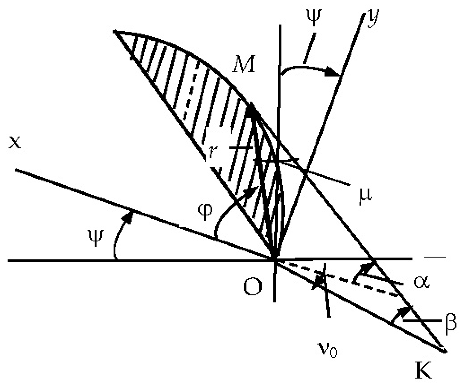
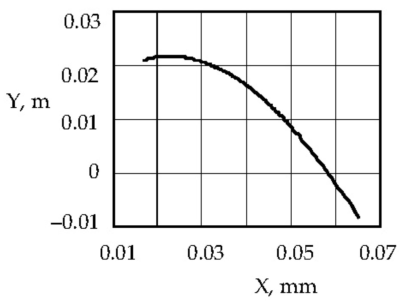
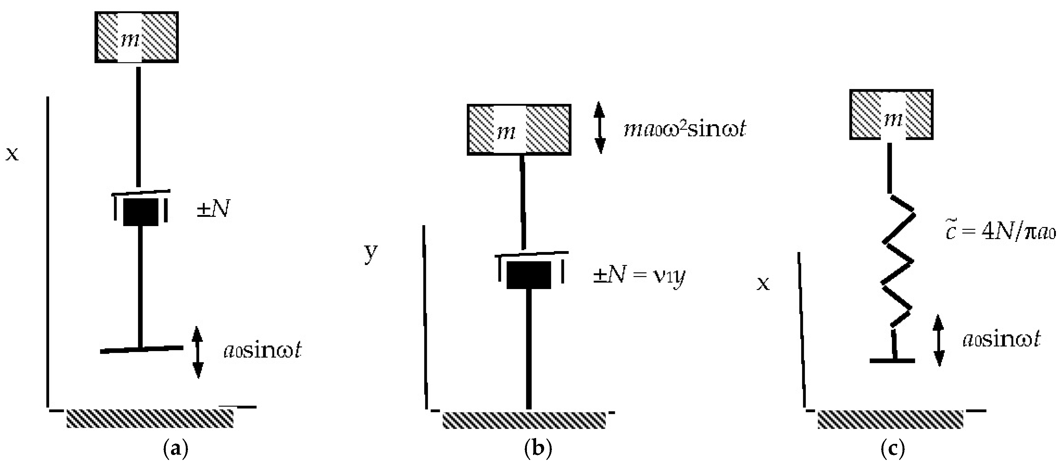
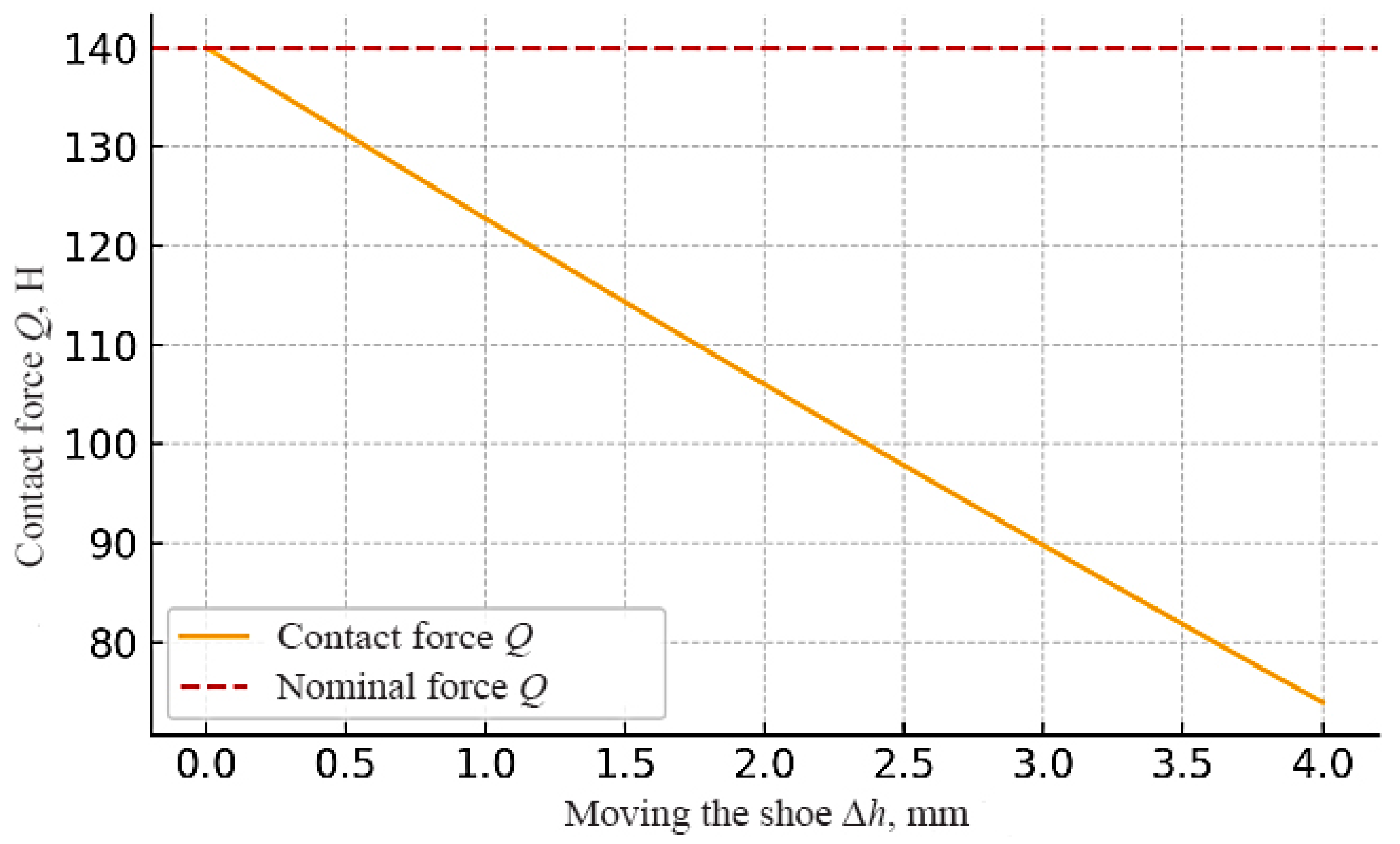
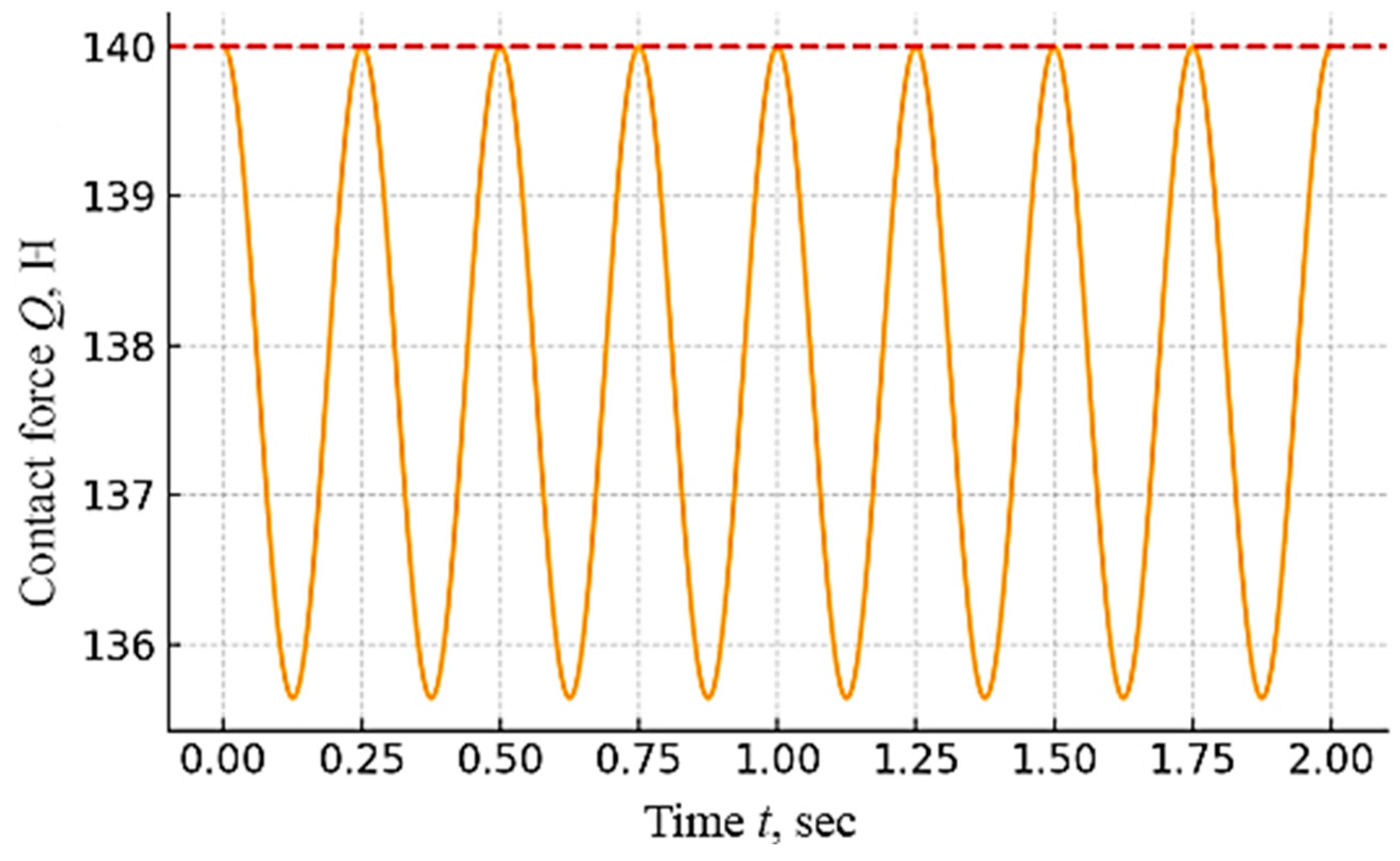
Disclaimer/Publisher’s Note: The statements, opinions and data contained in all publications are solely those of the individual author(s) and contributor(s) and not of MDPI and/or the editor(s). MDPI and/or the editor(s) disclaim responsibility for any injury to people or property resulting from any ideas, methods, instructions or products referred to in the content. |
© 2025 by the authors. Licensee MDPI, Basel, Switzerland. This article is an open access article distributed under the terms and conditions of the Creative Commons Attribution (CC BY) license (https://creativecommons.org/licenses/by/4.0/).