Article

The Solution Method for Ultra-Fine Group Slowing-Down Equations Applicable to Stochastic Media

1
College of Nuclear Science and Technology, Naval University of Engineering, Wuhan 430033, China
2
College of Electrical Engineering, Naval University of Engineering, Wuhan 430033, China
3
Laboratory for Advanced Nuclear Energy Theory and Applications, Zhejiang Institute of Modern Physics, Department of Physics, Zhejiang University, Hangzhou 310027, China
*
Authors to whom correspondence should be addressed.
Mathematics 2025, 13(11), 1857; https://doi.org/10.3390/math13111857
Submission received: 13 April 2025 / Revised: 26 May 2025 / Accepted: 30 May 2025 / Published: 2 June 2025
(This article belongs to the Section C: Mathematical Analysis)

Abstract

:
This study presents an innovative solution method for ultra-fine group slowing-down equations tailored to stochastic media with double heterogeneity (DH), focusing on advanced nuclear fuels such as fully ceramic microencapsulated (FCM) fuel and Mixed Oxide (MOX) fuel. Addressing the limitations of conventional resonance calculation methods in handling DH effects, the proposed UFGSP method (the ultra-fine group slowing-down method with the Sanchez–Pomraning method) integrates the Sanchez–Pomraning technique with the ultra-fine group transport theory to resolve spatially dependent resonance cross-sections in both matrix and particle phases. The method employs high-fidelity geometric modeling, iterative cross-section homogenization, and flux reconstruction to capture neutron self-shielding effects in stochastically distributed media. Validation across seven FCM fuel cases, four poison particle configurations (BISO/QUADRISO, Bi/Tri-structural Isotropic), and four plutonium spot problems demonstrated exceptional accuracy, with maximum deviations in effective multiplication factor keff and resonance cross-sections remaining within ±138 pcm and ±2.4%, respectively. Key innovations include the ability to resolve radial flux distributions within TRISO particles and address resonance interference in MOX fuel matrices. The results confirm that the UFGSP method significantly enhances computational precision for DH problems, offering a robust tool for next-generation reactor design and safety analysis.

1. Introduction

As a low-carbon, clean, and high-energy-density baseload energy source, nuclear power is playing an irreplaceable strategic role in addressing global climate change and achieving carbon neutrality goals. According to the 2024 Energy Outlook Report [1] by the International Atomic Energy Agency (IAEA), nuclear power generation accounts for 10.2% of the global electricity supply, with this proportion reaching 20–50% in advanced nuclear energy countries. As the mainstream reactor type in current nuclear power plants, the pressurized water reactor (PWR) employs light water as both a moderator and a coolant. The accuracy of its core physics modeling directly impacts critical aspects such as core design optimization, operational strategy formulation, and safety margin evaluation [2].
In the field of reactor physics analysis, traditional deterministic methods, which are based on diffusion theory or transport theory for mathematical modeling, face significant challenges when dealing with strongly doubly heterogeneous media [3]. Particularly with the advancement of Generation IV nuclear energy system development, the engineering application of advanced fuel forms such as fully ceramic micro-encapsulated fuel (FCM) and Mixed Oxide fuel (MOX) has introduced pronounced double heterogeneity (DH) effects that pose severe challenges to conventional analysis methods. This DH effect arises from the heterogeneous distribution characteristics at different spatial scales within the fuel elements: in FCM fuel, Tri-structural Isotropic (TRISO) fuel particles with diameters of approximately 0.8–1.0 mm are randomly dispersed in a graphite matrix, whereas in MOX fuel, plutonium-rich spots formed during the manufacturing process exhibit random spherical distributions at sub-millimeter scales [4].
From the perspective of neutron physics, this doubly heterogeneous structure affects core performance in three key aspects: First, in the resonance absorption region (0.1 eV–10 keV), the spatial self-shielding effect of fuel particles causes traditional homogenization methods to overestimate the effective resonance integral. Second, during neutron transport, the interface effects between randomly distributed fuel phases and matrix phases induce localized perturbations in neutron flux. Finally, at the core power distribution level, microscopic heterogeneity may lead to power peaking factors (PPFs) exceeding safety limits due to neutron spectrum hardening effects [5].
The U.S. Nuclear Regulatory Commission (NRC) explicitly states in the NUREG-0800 Standard Review Plan that for DH fuel assemblies, validated high-fidelity modeling methods must be employed for safety analysis [6]. Among these challenges, effectively treating resonance cross-sections has become a key research difficulty. To overcome the limitations of traditional methods, the international academic community is currently advancing research along two main technical pathways:
(1) Developing multi-scale coupling algorithms based on the Monte Carlo method, which involve constructing high-resolution geometric models at the fuel particle scale while incorporating variance reduction techniques to improve computational efficiency [7].
(2) Enhancing deterministic methods by refining ultra-fine group slowing-down equation solutions and developing equivalent homogenization methods suitable for stochastic media [8].
For example, the APOLLO3 code developed by the French Alternative Energies and Atomic Energy Commission (CEA) employs a self-shielding correction model based on the subgroup method, converting the random distribution of TRISO particles into a probability density function for statistical treatment [9]. Meanwhile, the MC2-3 code developed by the Argonne National Laboratory (ANL) in the U.S. achieves efficient coupling between the Monte Carlo methods and multi-group transport equations [10].
Currently, deterministic neutron transport equation solvers remain the mainstream approach for reactor physics numerical simulations. Therefore, it is essential to develop neutron transport equation-solving methods suitable for randomly distributed media under doubly heterogeneous conditions.
To address this issue, Bende et al. [11] proposed the Dancoff method in 1999. This method first derives the neutron first-flight collision probability and transmission probability to calculate the probability of a neutron escaping from one fuel particle to another. Based on this escape probability, the average Dancoff factor is computed, which is then used to correct the cross-sections. However, the derivation of the Dancoff method was based on a non-coated fuel particle model for High-Temperature Gas-cooled Reactors (HTGRs), making it unsuitable for the multi-layered spherical structure of fully ceramic micro-encapsulated (FCM) fuel. Ji et al. [12] improved the Dancoff method by proposing an average Dancoff factor calculation method based on a double-sphere model. By incorporating the chord length method to account for the multi-layered spherical structure, they extended the Dancoff method to TRISO particle calculations. Kim et al. [13] introduced a method using the average Dancoff factor to correct the background cross-section under double heterogeneity (DH) conditions and then inversely derived the effective resonance cross-section using resonance integral tables. However, due to the complexity of Dancoff factor calculations and the numerous approximations involved, this approach introduces additional biases. William [14,15] and She et al. [16] proposed the disadvantage factor method, initially applied to HTGRs. The core idea of this method is to simplify the doubly heterogeneous system into a conventional singly heterogeneous rod lattice problem, allowing the direct use of traditional resonance calculation methods to determine effective cross-sections. He [17] and Yin et al. [18] combined the disadvantage factor method with subgroup methods and ultra-fine group methods, applying it to FCM fuel resonance cross-section calculations. By homogenizing TRISO particles and matrix materials into a 1D model to compute the defect factor, this approach can be effectively integrated with traditional resonance calculation methods. However, it struggles to accurately resolve the fine spatial distribution of resonance cross-sections and neutron flux inside fuel particles.
Sanchez and Pomraning [19] proposed the Sanchez–Pomraning method to handle doubly heterogeneous geometries, which can be coupled with conventional transport methods such as the Method of Characteristics (MOC) [20]. This method iteratively computes the equivalent total cross-sections and source terms for each layer of the particle and the matrix material, and then defines an update equation to correct the angular flux exiting the particle. After obtaining the matrix flux, the flux reconstruction method is used to recover the flux distribution inside each layer of the particle. The Sanchez–Pomraning method laid the foundation for solving subgroup fixed-source equations under double heterogeneity. Pogosbekyan et al. [21] applied this method to subgroup resonance calculations. However, resonance interference effects under double heterogeneity are more complex, and the background iteration method suffers from low accuracy. Since calculating interference factors under double heterogeneity is extremely challenging, traditional subgroup resonance interference methods fail to accurately account for these effects.
Currently, the most precise method for handling resonance interference is the ultra-fine group method [22]. Its fundamental approach involves extremely fine energy group division in the resonance energy range to avoid intra-group resonance peak treatment. Within each fine energy group, a simplified neutron transport equation (also called the neutron slowing-down equation) is established. The neutron flux distribution is then computed top-down for each energy group and flat source region, yielding a problem-dependent ultra-fine group neutron spectrum to achieve accurate resonance self-shielding treatment. The ultra-fine group method originated from Kier’s [23] approach of calculating two-region cell resonance integrals in fine energy groups. Building on this, the first practical ultra-fine group code, RABBLE [11], was developed. Since then, the ultra-fine group method has been widely applied in neutronics codes [24,25,26]. However, due to the need to solve the slowing-down equation in ultra-fine (or continuous-energy) groups, the computational cost is high. Codes like PEACO [13] significantly improve computational efficiency by precomputing collision probability interpolation tables, but their geometric modeling capability is limited. Alternatively, MOC-based fixed-source calculations can enhance geometric flexibility [27,28], though at the cost of reduced computational efficiency compared to PEACO-like methods. Recent work by Hassan Dana Mazraeh et al. [29] demonstrated the potential of hybrid methods like GEPINNs (grammatical evolution and physics-informed neural networks) for solving complex differential equations, such as the Lane–Emden equation. While the UFGSP method focuses on deterministic transport, the future integration of AI techniques could further accelerate resonance calculations or optimize geometric modeling.
Therefore, it is necessary to investigate slowing-down equation solvers for stochastic media based on ultra-fine group methods. Theoretical innovations in neutron transport for randomly distributed media and the development of corresponding computational tools have become some of the most pressing challenges in reactor physics. The scientific value of this research lies not only in advancing fundamental neutron transport theory but also in its significant engineering implications for next-generation nuclear fuel development, reactor safety analysis, and improving the economic competitiveness of nuclear energy systems.

2. Materials and Methods

2.1. Ultra-Fine Group Slowing-Down Equation

The energy range of the resolved resonance region typically spans 1 eV to 10 keV. Since fission neutrons have energies significantly higher than 10 keV, it can be assumed that no fission neutrons are generated within this energy range. Additionally, neutrons below 10 keV hardly undergo inelastic scattering, meaning the scattering source term can be simplified to account only for isotropic elastic scattering, while up-scattering can be neglected. Therefore, isotropic scattering is valid in the resolved resonance region (0.1 eV–10 keV) where elastic scattering dominates. This simplification reduces angular flux coupling without sacrificing accuracy for DH systems. Under these conditions, the neutron slowing-down equation can be expressed in the following form [30,31]:
Ω ϕ r , u , Ω + Σ t r , u ϕ r , u = u ln 1 / α u Σ s r , u ϕ r , u 1 α e u u d u
where α = [(A − 1)/(A + 1)]2, A represents the atomic mass of the target nuclide, E represents the neutron energy, u is the lethargy calculated as u = ln(E0/E), and E0 = 10 MeV. The boundary conditions in this work were set to be the reflective boundary condition.
If there is more than one nuclide in region k, Equation (1) could be rewritten as follows:
Ω ϕ r , u , Ω + i Σ i , t k r , u ϕ r , u = Q r , u
Q r , u = i u Δ i u Σ i , s k r , u ϕ r , u 1 1 α e u u d u
where Q is the neutron source item; Σ i , x k represents the macroscopic cross-section for the i-th nuclide and reaction type x; Δ denotes the maximum logarithmic energy decrement that nuclide i can attain; and 1 − α is the maximum energy fraction that nuclide i may lose in a single collision.
By solving the slowing-down equations sequentially from the highest energy downward based on continuous-energy point cross-sections, the continuous neutron scalar flux can be obtained. Subsequently, using Equation (4), the within-group effective self-shielded cross-sections in multigroup format can be derived.
σ x , G = Δ u G σ x u ϕ u d u Δ u G ϕ u d u
where G is the group index, σx represents the microscopic cross-section for reaction type x, and ϕ is the neutron scalar flux.
When applying the above conclusions to practical resonance calculations, for a system containing multiple resonant and non-resonant materials, we first spatially discretize the system into multiple mesh regions. Within each mesh region, the source term is assumed to be uniform. Subsequently, the resonance energy range is subdivided into extremely fine energy groups, termed ultra-fine groups. To ensure that neutrons undergo only one collision within the energy range covered by a single ultra-fine group, the energy width of each ultra-fine group is set much smaller than the maximum logarithmic energy decrement (Δ) attainable by neutrons after a single collision with the heaviest nuclide in the system. Under these conditions, the scattering source in ultra-fine group g within a mesh region can be formulated as follows:
Q g = j = 1 J n = 1 L j P n j Σ s , g n j ϕ g n Δ u f
where Pnj is defined as the probability of neutrons scattering from group n to g after interacting with material j. Lj denotes the maximum number of energy groups that a neutron may traverse after a single collision with material j. Σ s , g n j represents the macroscopic scattering cross-section of group gn, and ϕ is the neutron scalar flux.
Since the number of reachable energy groups after neutron scattering is extremely large, directly solving Equation (5) would be computationally prohibitive. Therefore, a reformulation is necessary. First, considering Pnj, the probability that a neutron’s energy decreases from u′ to u after scattering can be expressed as follows:
P u u = 1 1 α e u u
where u − ∆ ≤ u′ ≤ u.
The probability that neutrons pass through n ultra-fine groups after scattering is as follows:
P n Δ u f = 1 1 α u 0 u 0 + Δ u f d u u 0 n Δ u f u 0 n 1 Δ u f d u e u u
Substituting Equation (6) into Equation (7), we can obtain the following:
P n Δ u f = 1 1 α 1 e Δ u f 2 e n 1 Δ u f
From Equation (8), the following rule can be derived:
P n Δ u f = 1 1 α 1 e Δ u f 2 e n 1 Δ u f
P n = e Δ u f P n 1
Substituting Equations (9) and (10) into Equation (5), we obtain the following:
Q g = P 1 Σ g 1 ϕ g 1 + [ P 2 Σ g 2 ϕ g 2 + P 3 Σ g 3 ϕ g 3 + + P L Σ g L + 1 ϕ g L + 1 + P L Σ g L ϕ g L + P L + 1 Σ g L 1 ϕ g L 1 ] P L + 1 Σ g L 1 ϕ g L 1
According to Equation (9), it can be seen that the term in parentheses in Equation (11) is Q g 1 e Δ u f , where Q g 1 represents the scattering source term of the (g − 1)th ultra-fine group. Thus, the recursive relationship for the ultra-fine group scattering source term can be obtained:
Q g = Q g 1 e Δ u f + P 1 Σ g 1 ϕ g 1 P L + 1 Σ g L 1 ϕ g L 1 e Δ u f
For the recursive relationship in Equation (11), the first step is to calculate the scattering source of the leading ultra-fine group. The moderation neutrons in the leading ultra-fine group originate from the energy range above the resonance calculation region. In this higher energy range, the cross-sections vary relatively smoothly with energy. Therefore, the cross-sections of nuclides in this energy range can be approximated as constants, and the flux distribution within this region is assumed to follow the 1/E law. Based on Equation (5), the scattering source of the leading ultra-fine group can then be computed. Once the scattering source of the leading ultra-fine group is obtained, the neutron flux in this group can be determined through a single-group fixed-source calculation. The resulting neutron flux is then used to compute the scattering source for the next energy group. By iterating this process sequentially, a fine-resolution energy spectrum across the entire ultra-fine group range can be derived, ultimately enabling the computation of the resonance self-shielded cross-sections for a specific resonance group.
The accuracy of the fixed-source calculations directly affects the precision of the resonance self-shielded cross-sections. In this work, the Method of Characteristics was coupled to perform the intra-group fixed-source calculations for ultra-fine groups. The Method of Characteristics (MOC) transforms the neutron transport equation into equations along characteristic lines at specific angular directions using mathematical techniques. This approach simultaneously handles spatial and angular variables, enabling the treatment of arbitrary geometries. The modular MOC approach primarily refers to the characteristic line generation methodology. This method generates characteristic lines on a modular basis, ensuring that lines in adjacent modules are seamlessly connected end-to-end.

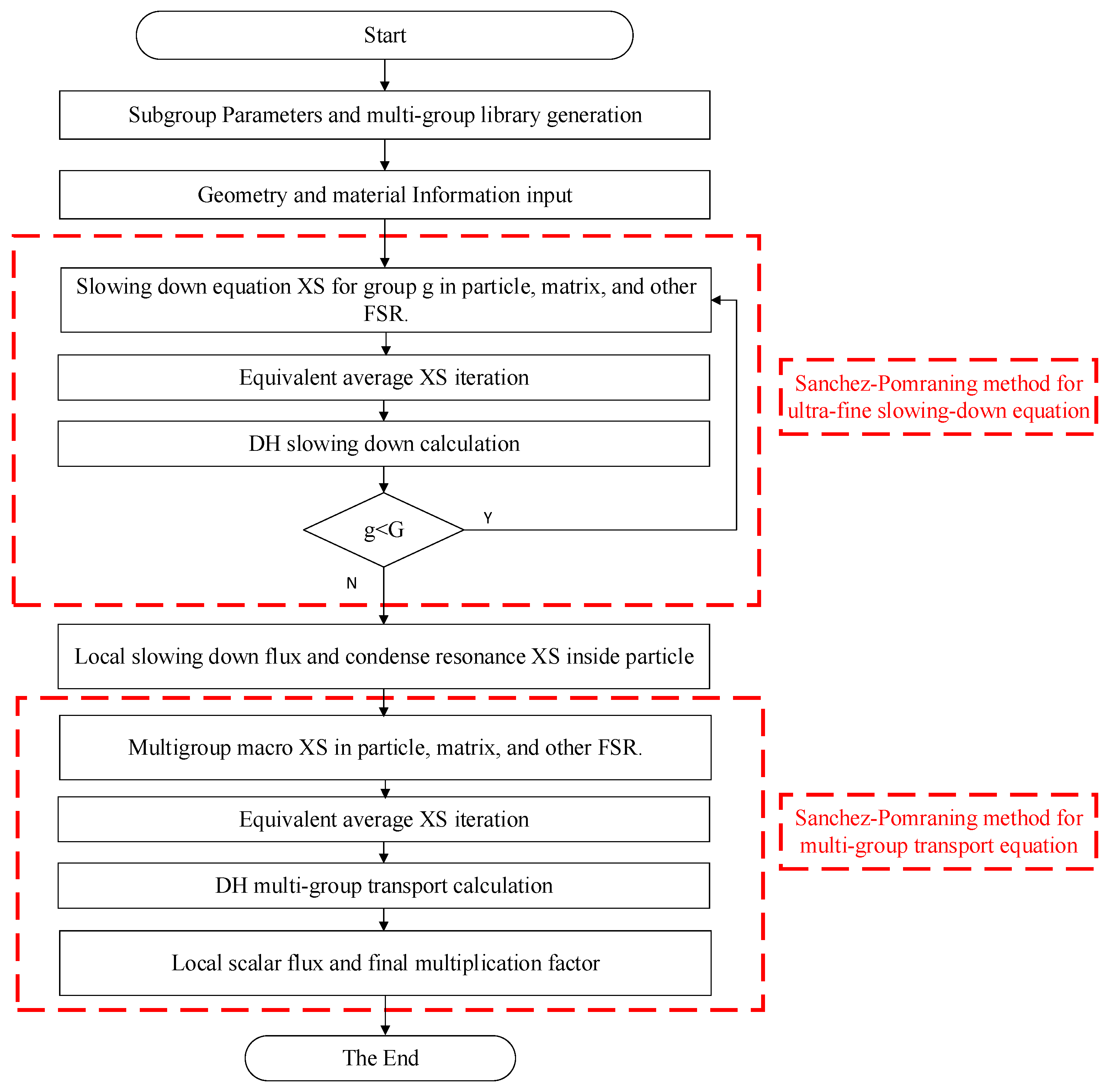
2.2. Stochastic Medium Ultra-Fine Group Equations Based on the Sanchez–Pomraning Method

In traditional pressurized water reactor (PWR) problems, only the heterogeneity arising from rod-and-lattice structures exists. However, for accident-tolerant fuels (ATFs) such as fully ceramic micro-encapsulated (FCM) fuel, the fuel particles are distributed within a silicon carbide (SiC) matrix inside the fuel rod. As shown in Figure 1, the random distribution of fuel particles introduces a second layer of heterogeneity into core neutronics calculations. Additionally, for MOX fuel, due to manufacturing limitations, plutonium isotopes in the fuel rod form spherical agglomerations, where PuO2 particles are dispersed within a UO2 matrix, also creating a dual heterogeneity phenomenon. Since the precise coordinates of the particles are difficult to determine, resonance calculations under double heterogeneity conditions cannot be performed directly. To address this, international approaches such as the volume-weighting method, the Dancoff factor method, and the disadvantage factor method have been proposed. These methods fundamentally aim to compute equivalent models by homogenizing fuel particles and the matrix, thereby converting the dual heterogeneity problem into a conventional single-heterogeneity problem, which is then solved using standard resonance and transport methods. A common limitation of these methods is their inability to resolve the fine spatial distributions of cross-sections and flux within individual particles, as they only provide homogenized resonance cross-sections for the mixed material. In recent years, the Sanchez–Pomraning method has been increasingly applied to MOC transport calculations for dual heterogeneity. This method iteratively updates effective cross-sections, computes the matrix flux using governing equations, and then reconstructs the detailed flux distribution inside the particles based on the matrix flux. The subgroup method exhibits intrinsic compatibility with transport solvers, making the Sanchez–Pomraning method equally applicable to subgroup resonance calculations. This section proposes a Sanchez–Pomraning-based ultrafine group equation solution framework. First, the traditional MOC method is enhanced using the Sanchez–Pomraning approach to enable transport calculations in dual-heterogeneity geometries. Subsequently, this improved method is applied to both ultrafine group equations and multigroup transport equations, achieving refined calculations for dual-heterogeneity problems.

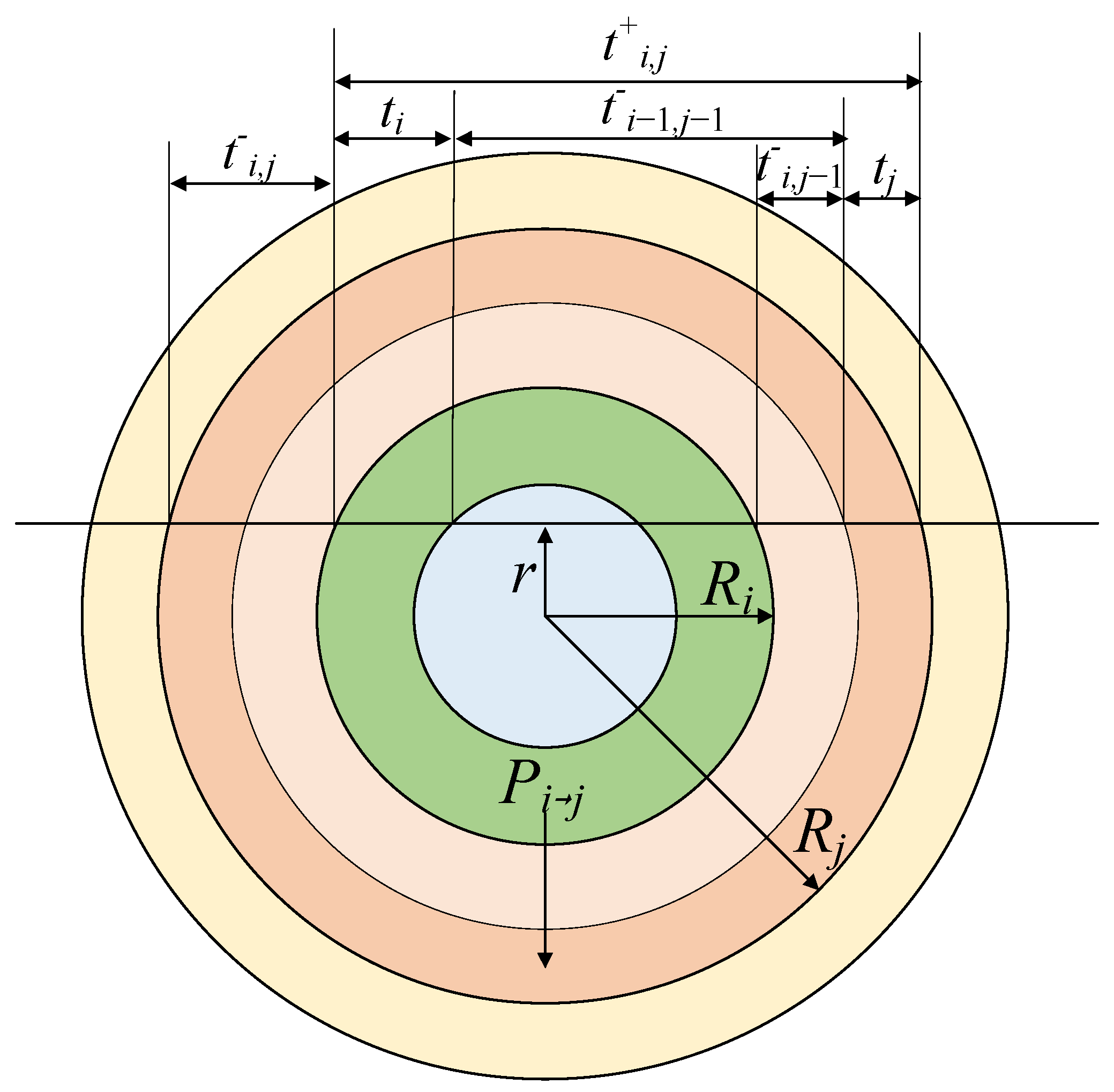
2.2.1. Sanchez–Pomraning Iteration

Due to the difficulty in determining the coordinates of randomly distributed fuel particles, the conventional Method of Characteristics (MOC) cannot perform characteristic line scanning for fuel particles within the flat source region. Therefore, it is necessary to first homogenize the total cross-sections of each layer of the particles and the matrix. Unlike the conventional volume-weighted method, the Sanchez–Pomraning method iteratively calculates the equivalent total cross-section of the flat source region based on the probability of neutrons escaping from each layer of the fuel particles, and calculates the equivalent source term through the equivalent total cross-section and the double heterogeneity asymptotic flux. During the characteristic line scanning process, the renormalization factor is calculated through the update equation, and then the outgoing flux of the flat source region is corrected. The flux in the flat source region that converges iteratively through this process is the flux of the FCM fuel rod matrix, and the flux of each layer of the fuel particles can be calculated according to the reconstruction formula [32,33,34].
The trajectory of neutrons within the fuel particle is illustrated in Figure 2. Here, Pij represents the probability that a neutron located in the i-th spherical shell moves to the j-th shell and undergoes its first collision, while Ei denotes the probability that a neutron in the i-th spherical shell escapes the fuel particle without any collision. R is the radius of the spherical layer, and the length of each segment t can be directly determined based on geometric relationships. For an infinitely thin spherical layer dr at a distance r from the center of the sphere, Pdrj can be calculated using Equation (13):
P d r j = 2 π r d r Σ i V i e t i 1 , j 1 + + e t i , j 1 + 1 e t i 2
where Σi and Vi are the macro total cross section and the volume of region I, respectively.
In Equation (13), integrating over dr from 0 to Ri yields the value of Pij. Since different spherical shells of the fuel particle have distinct material cross-sections, the integration must be performed segment-wise across the respective shells. The final expression for Pij is given by Equation (13), and the numerical integration can be solved using the Gauss–Seidel method.
P i j = 2 π Σ i V i k = 1 i R k 1 R k r d r e t i 1 , j 1 + + e t i , j 1 + 1 e t i 2
Similar to Pij, the probability Pii that a neutron undergoes a collision within its current fuel layer can be calculated using Equation (15):
P i i = 2 π Σ i V i k = 1 i R k 1 R k r d r e t i 1 , i 1 + 1 e t i 2 + 2 τ i + e t i 1
Based on the reciprocity relation (14), the reverse collision probability Pji can be derived inversely using Equation (13).
V i Σ i P i j = V j Σ j P j i
The escape probability of neutrons from the i-th layer can be calculated using Equation (17) after obtaining the inter-layer collision probabilities.
E i = 1 j = 1 N P i j
where N is the layer number of the fuel particle.
The transport calculation requires the iterative solution of the equivalent total cross-section for the flat-source region, as given by Equation (18):
Σ t n + 1 = Σ t , m + 1 p m h = 1 H i = 1 I p h i Σ t , h i Σ t n E ^ h i
where the subscript h represents particles; m represents the matrix; pm and phi denote the volume fractions of the matrix and the i-th fuel layer of the h-th fuel particle, respectively; E ^ is the reduced escape probability; and Σ t n + 1 is clarified as the equivalent total cross-section at iteration n.
The calculation process of E ^ is similarly based on Equations (15)–(17), where the total cross-section value is taken as Σt,hi minus Σ n ( t ) . Starting from Equation (18), Σ n ( t ) is first initialized to 0, followed by the iterative computation of Σ ( n + 1 ) t until convergence is achieved. Using the converged equivalent total cross-section Σt, the equivalent source term can then be calculated via Equation (19):
q = Σ t ϕ a s
where ϕas denotes the asymptotic flux. Under doubly heterogeneous conditions, its calculation formula is given by Equation (20):
ϕ a s = q m + 1 p m h = 1 H i = 1 I p h i q h i E h i / Σ ˜ t
where Σ ˜ t is obtained by Equation (21):
Σ ˜ t = Σ t , m + 1 p m h = 1 H i = 1 I p h i Σ t , h i E h i
qm and qhi are defined as the actual source terms for the matrix and each layer of the fuel particle, respectively. For energy group g, their calculation methods are given by Equation (22):
q g = g G Σ h i , s , g g ϕ h i , g + 1 k e f f χ g g G v Σ h i , f , g ϕ h i , g Particle g G Σ m , s , g g ϕ m , g + 1 k e f f χ g g G v Σ m , f , g ϕ m , g Matrix
where ϕm and ϕhi denote the actual fluxes in the matrix and each layer of the fuel particle, respectively.
The update equation is calculated based on collision probabilities and escape probabilities, as shown in Equation (23):
ϕ o u t x = 0 L d y S h Q h y + ϕ i n , h x y f h y e Σ h y Particle ϕ o u t , m 0 e Σ m + 1 / l m ¯ x + 0 x d y S m + ϕ i n , m x y / l m e Σ m + 1 / l m ¯ y Matrix
where Q represents the cumulative chord length distribution function, f denotes the probability cumulative function, S is the source term, and l stands for the chord length.

2.2.2. MOC Integration Based on Sanchez–Pomraning Method

The Sanchez–Pomraning method simplifies Equation (23) through a boundary layer assumption, introducing a renormalized factor rc to correct the outgoing neutron angular flux ϕout in the Method of Characteristics (MOC) flat-source regions, which is shown in Equation (24):
ϕ o u t = ϕ i n + r c 1 e Σ t L ϕ a s ϕ i n
For flat-source regions containing fuel particles, rc can be calculated using Equation (24). For regions without fuel particles (such as the moderator or cladding), rc takes a value of 1, in which case Equation (24) becomes identical to the conventional MOC outgoing angular flux calculation formula. Under doubly heterogeneous conditions, the flux obtained through Equation (24) correction represents the actual matrix flux ϕm.
r c = p m + h = 1 H i = 1 I p h i E ^ h i
After obtaining the matrix flux, the flux for each layer of the fuel particles can then be calculated using Equation (26):
ϕ h i = E ^ h i ϕ m + E h i E ^ h i ϕ a s + 1 V h i Σ h i , t i = 1 I V h i q h i P h , i j
This study presents an enhanced ultra-fine group (UFG) approach incorporating modifications derived from the Sanchez–Pomraning (SP) technique, hereafter referred to as the UFGSP method. The removal cross-section formulation employed in the ultra-fine group slowing-down equations maintains consistency with Equation (18). By integrating Equations (12) and (22), we derived the comprehensive source terms for both particulate and matrix components within the ultra-fine group framework, as presented in Equation (27).
q g = Q h i , g 1 e Δ u g 1 + n N f h i , 1 , n Σ h i , n , s , g 1 φ h i , g 1 n N f h i , L , n Σ h i , n , s , g L 1 φ h i , g L 1 e Δ u g L 1 P a r t i c l e Q m , g 1 e Δ u g 1 + n N f m , 1 , n Σ m , n , s , g 1 φ m , g 1 n N f m , L , n Σ m , n , s , g L 1 φ m , g L 1 e Δ u g L 1 M a t r i x
The computational procedure initiates with fast group flux determination using asymptotic flux values, followed by sequential resonance group flux calculations. The condensed effective resonance parameters for the predefined group structure are shown in Equation (28).
σ x = g r = 1 G r σ x , g r ϕ g r g r = 1 G r ϕ g r
where x represents the reaction channel type, and Gr denotes the number of ultra-fine groups corresponding to the current resonance energy interval in the multi-group structure.
The overall calculating process of the UFGSP method is shown in Figure 3. Notably, the method requires just two applications of the Sanchez–Pomraning technique: first for doubly heterogeneous slowing-down equations and subsequently for multi-group transport solutions [35,36,37].

3. Numerical Validation

In this section, various fully ceramic micro-encapsulated (FCM) fuel problems with different packing fractions and geometric configurations were selected for validation. Additionally, calculations and analyses were performed on issues involving poison particles and plutonium spots in traditional MOX fuels to verify the capability of the resonance module in the UFGSP code for handling doubly heterogeneous problems. The referenced data were generated by the Monte Carlo code OpenMC [37], which serves as the reference solution. The OpenMC calculations explicitly model stochastic particle distributions and employ continuous-energy nuclear data libraries. The computer information for numerical validation is AMD Ryzen7 4800 H 2.90 GHz.

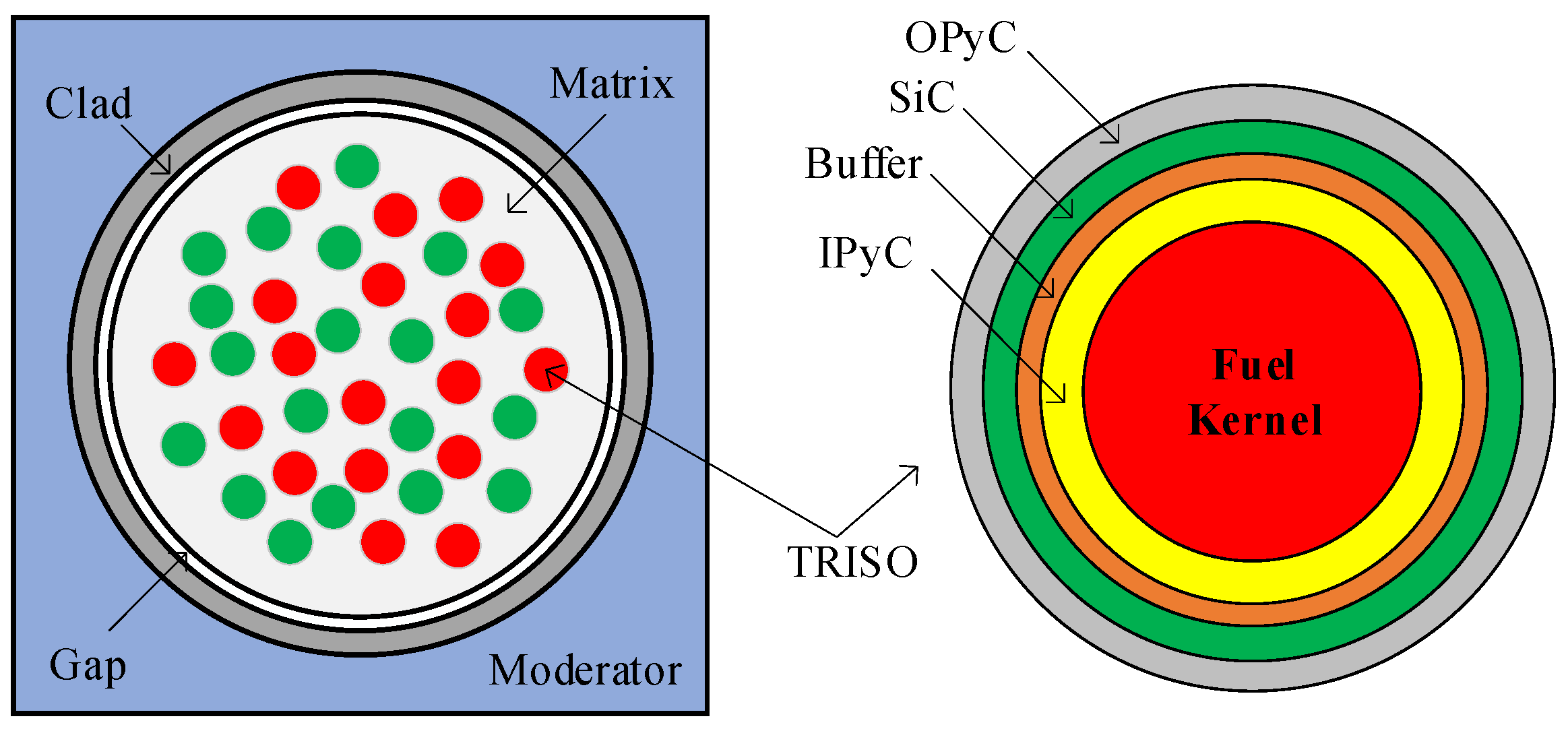
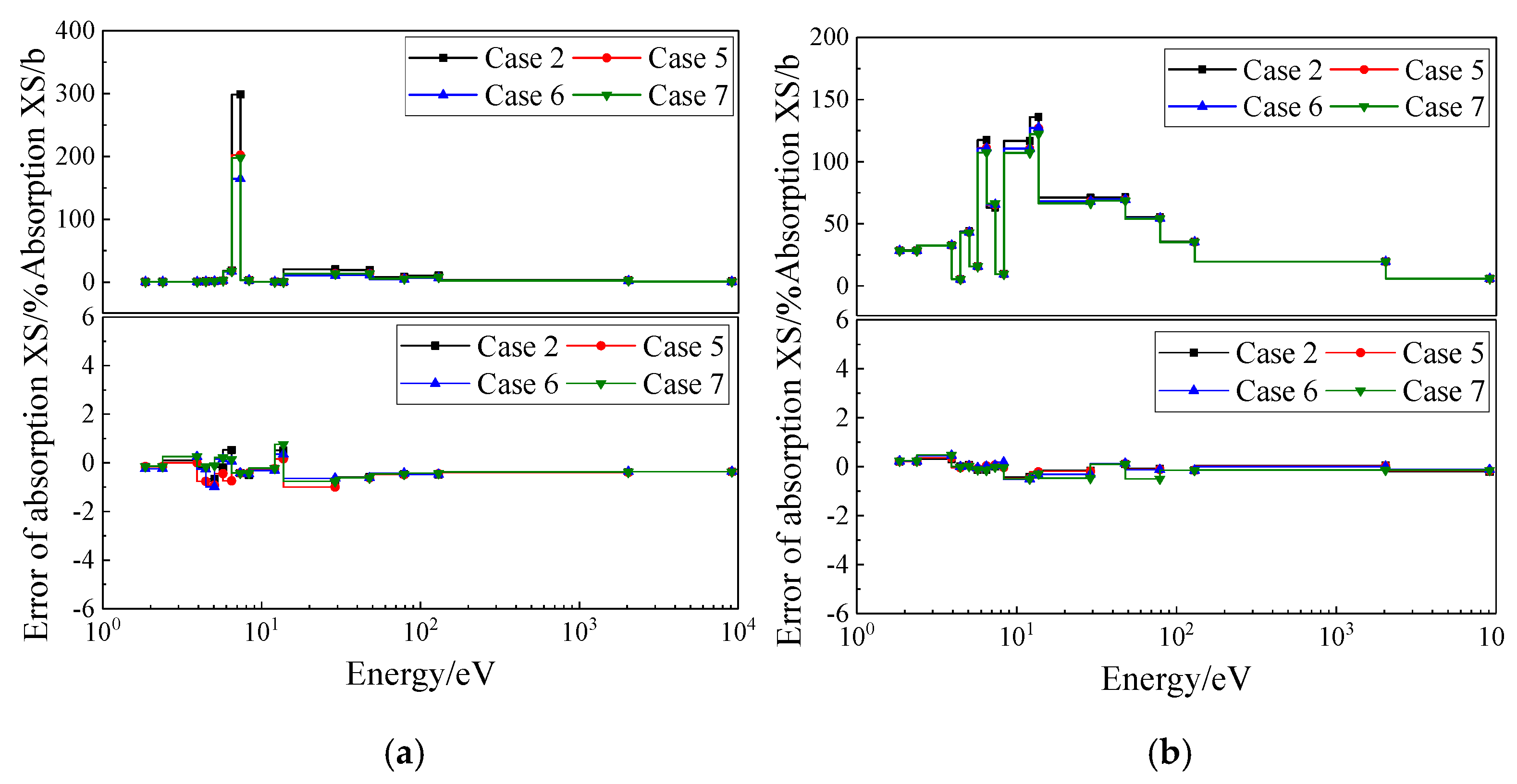
3.1. Typical FCM Fuel Problem

The basic structure of the FCM fuel is illustrated in Figure 1. The fuel kernel of the TRISO particles consists of UC fuel with an enrichment of 17.8 wt%, and the matrix material is SiC. The geometric configurations are listed in Table 1, and the material nuclide density information is provided in reference [38,39]. This section selects seven typical FCM fuel test cases. The first five cases have particle packing fractions of 1%, 10%, 20%, 30%, and 40%, respectively, with TRISO particles of Geometry A. The sixth and seventh cases correspond to Geometry B and Geometry C, both with a packing fraction of 30%. The computational parameters of the MOC are set as follows: 16 azimuthal angles and three polar angles per octant, a ray-spacing of 0.01 cm, and a system temperature of 300 K. The reference solutions are provided by the Monte Carlo code OpenMC [37], where the calculations employ randomly packed particles and an explicit modeling approach.
Table 2 presents the basic information and effective multiplication factor keff results for different test cases. The computational accuracy is high across all packing fractions, with a maximum absolute deviation of 64 pcm. Taking Cases 2, 5, 6, and 7 as examples, Figure 4 shows the computational deviations of the absorption cross-sections for 235U and 238U in this series of problems. Test cases with lower packing fractions exhibit higher dilution levels and larger background cross-sections, resulting in relatively larger resonance cross-sections, whereas cases with higher packing fractions show smaller resonance cross-sections. The UFGSP method can accurately compute this phenomenon. For the 40% packing fraction case, the computational deviations for both 235U and 238U cross-sections remain within ±1%, demonstrating high accuracy. For the 10% packing fraction case, the deviation in the 238U cross-section increases, reaching relative deviations of 1.35% and 1.49% in the energy ranges of 13.71–29.02 eV and 78.89–130.07 eV, respectively. Since the resonance cross-sections in these energy ranges are relatively small, their impact on reaction rates is minor. Since the calculating time of different computational devices is different, the MOC iteration number was compared instead in this work, which is shown in Table 2. It can be seen that the iteration number is decreased with the packing fraction. However, it is still similar to the conventional method since the key calculating formula of the MOC process, which accounts for the greatest time cost of the whole calculating process, remains the same. In this way, although the iterative cross-section homogenization increases runtime compared to conventional MOC, the transport process is still efficient for typical calculations. Cases 6 and 7, which feature different geometric dimensions, also achieve high accuracy in resonance cross-section calculations, with most deviations staying within ±1% and the maximum deviation remaining around 1%. Table 3 summarizes the maximum (MAX), average (AVG), and root-mean-square (RMS) deviations in resonance cross-section calculations for different test cases, all of which exhibit high computational precision.
Taking Case 6 as an example, Figure 5 presents the radial distribution of the 238U absorption cross-section within the fuel kernel of TRISO particles. Similar to the spatial self-shielding effect observed in fuel rods, the fuel kernel also exhibits neutron shielding. Neutron reactions primarily concentrate near the surface of the fuel kernel, while the resonance cross-section in the inner region shows an increasing trend along the radial direction. The calculation of radial distribution is crucial for subsequent burnup analysis. However, traditional doubly heterogeneous resonance methods, such as the defect factor method or the Dancoff method, cannot resolve the internal resonance cross-section distribution within the fuel kernel. The UFGSP method, based on the Sanchez–Pomraning method, enables the precise computation of the radial cross-section distribution in the fuel kernel. As shown in Figure 5, the computational deviations for the three resonant energy groups remain below ±1%, demonstrating high accuracy.

3.2. Burnable Poison and Pu Spot Problem

This section validates two special doubly heterogeneous problems: FCM fuel containing poison particles and the plutonium spot issue in conventional PWRs, as shown in Figure 6. For the poison particle problem, QUADRISO particles are conventional TRISO particles with an additional layer of burnable poison coated outside the fuel kernel, while BISO particles replace the TRISO fuel kernel entirely with a burnable poison kernel. The plutonium spot problem refers to the phenomenon where PuO2 particles are randomly dispersed as spherical inclusions within UO2 fuel rods in MOX fuel, where traditional methods typically homogenize the plutonium spots with the fuel matrix, whereas the UFGSP method can directly perform doubly heterogeneous calculations for plutonium spots. The MOC computational parameters for this series of problems are set with 16 azimuthal angles and three polar angles per octant, a ray spacing of 0.01 cm, and a system temperature of 300 K, with reference solutions provided by the Monte Carlo code OpenMC.

3.2.1. Poison Problems

The dimensions and material types of the QUADRISO and BISO particles selected in this section are shown in Table 4, with the poison materials including both B4C and Gd2O3. The specific nuclide number densities are provided in references [37,38]. Four test cases were designed for this study: the first two cases involve fuel rods containing QUADRISO particles with a packing fraction of 30%, using B4C and Gd2O3 as the poison materials, respectively. The latter two cases feature BISO particles, where the fuel rods contain 33.8% TRISO particles and 10.8% BISO particles. The TRISO particle types are identical to those listed in Table 1, with the burnable poisons being B4C and Gd2O3, respectively.
Figure 7a presents the computational deviations of 238U absorption cross sections in the fuel kernels for all four test cases, with maximum deviations remaining within ±1%, demonstrating high computational accuracy. Figure 7b shows the absorption cross-section deviations for 155Gd and 157Gd in the two Gd2O3 test cases. Compared with 238U, the maximum deviations for Gd cross-sections are slightly larger due to more pronounced flux depression within Gd-containing particles. Table 5 summarizes the cross-section calculation results for both B4C and Gd2O3 poison problems, showing overall high computational accuracy. Table 6 presents the keff for all four poison test cases. For B4C cases and the Gd2O3 BISO case, keff deviations remain within ±100 pcm. The deviation increases to 138 pcm for the Gd2O3 QUADRISO case, which features relatively small keff values and is rarely encountered in practical PWR applications.

3.2.2. Pu Spot Problem

In the plutonium spot problem, the matrix material is UO2 while the fuel particles are uncoated PuO2 [40,41]. Compared with FCM fuel problems, the main challenge of plutonium spot problems lies in the fact that the fuel rod matrix itself exhibits strong resonance effects, which conventional doubly heterogeneous resonance calculation methods cannot simultaneously handle for both the matrix and fuel particles. For the test cases in this section, the matrix consists of UO2 with 0.16 wt% enrichment, while the particles are PuO2 with 1.5 wt% enrichment. The plutonium spots have a radius of 100 μm with packing fractions of 0.5%, 1%, 1.5%, and 2%, respectively. Detailed material nuclide compositions and geometric information are provided in reference [42].
Taking the plutonium spot problems with 1% or 2% packing fractions as examples, Figure 8a presents the calculation deviations of 238U absorption cross-sections in the UO2 matrix for these two cases. Although the packing fraction of plutonium spots is extremely small, the strong resonance interference effects of Pu isotopes significantly influence the 238U resonance cross-sections. As the packing fraction increases, the dilution effect on 238U intensifies, leading to larger resonance cross-section values. The matrix resonance cross-section calculations for different cases demonstrate high accuracy, with deviations for most energy groups remaining within ±1%. Figure 8b shows the calculation deviation distributions of 239Pu and 241Pu absorption cross-sections in the 1% packing fraction plutonium spots. Both Pu isotopes exhibit strong resonance peaks, with 241Pu showing particularly intense resonance peaks below 10 eV. The UFGSP method accurately describes the resonance peak distributions of 239Pu and 241Pu, with calculation deviations near resonance peaks all within ±1%. The maximum deviations across the entire energy range are −1.24% and −1.42%, respectively. Table 7 summarizes the overall resonance cross-section calculation deviations for the plutonium spot problems, showing high accuracy for both UO2 matrix and PuO2 fuel particle resonance cross-section calculations. Table 8 presents the effective multiplication factor calculation deviations for the plutonium spot problems, with absolute deviations for all cases remaining within ±100 pcm.

4. Discussion

The UFGSP method advances deterministic neutron transport by addressing two critical challenges in DH systems: spatial self-shielding in stochastic media and resonance interference between matrix and particle phases. Traditional approaches, such as the Dancoff factor or defect factor methods, rely on homogenization techniques that fail to resolve intra-particle flux gradients or matrix–particle resonance coupling. In contrast, the UFGSP method leverages the Sanchez–Pomraning iterative framework to decouple particle and matrix transport, enabling the precise calculation of equivalent cross-sections and angular flux corrections. However, computational costs remain a concern. While MOC-based angular discretization improves geometric flexibility, iterative cross-section homogenization and flux reconstruction increase the runtime compared to conventional MOCs. Overall, the main advantages over other existing methods and the potential future work are shown below.

4.1. Theoretical Advantages of UFGSP

(1) Spatial Resolution: Unlike homogenization-based methods (e.g., the Dancoff factor), the UFGSP method resolves radial flux gradients within TRISO particles.
(2) Resonance Interference Handling: The iterative Sanchez–Pomraning framework accounts for matrix–particle resonance coupling, addressing limitations of subgroup methods.
(3) Geometric Flexibility: MOC integration enables the treatment of irregular geometries (e.g., BISO/QUADRISO particles).
(4) Accuracy: Validated deviations in keff and cross-sections surpass traditional methods.

4.2. Computational Trade-Offs

The UFGSP method reduces approximations in DH treatments (e.g., no Dancoff factor fitting), but iterative cross-section homogenization increases the runtime compared to conventional MOCs. However, the UFGSP method achieves comparable accuracy to Monte Carlo (OpenMC) with 102–103 computational hours (minutes level compared to hours level).

4.3. Limitations and Future Work

The potential error may result from the iterative Sanchez–Pomraning method introducing truncation errors, which are mitigated by convergence criteria. Ultra-fine group discretization (0.01 eV resolution) minimizes intra-group resonance averaging errors. The UFGSP method currently assumes spherical fuel particles. Non-spherical geometries (e.g., cylindrical or irregular shapes) require modifications to the collision probability model. Furthermore, the method assumes isotropic scattering, limiting its direct applicability to highly anisotropic media (e.g., fast reactors). Future work could explore acceleration techniques, such as machine learning-aided collision probability precomputation or adaptive energy group condensation. Moreover, extending the UFGSP method to support generalized geometries via machine learning-aided collision probability precomputation and incorporating angular-dependent scattering kernels could be explored.

5. Conclusions

This study successfully developed and validated the UFGSP method, a high-precision solver for ultra-fine group slowing-down equations in doubly heterogeneous media. By integrating the Sanchez–Pomraning technique with MOC-based ultra-fine group slowing-down equations, the method overcame the limitations of traditional homogenization approaches, enabling the detailed resolution of resonance cross-sections in both stochastic particle distributions and matrix materials. Key achievements include the following:
(1) The accurate modeling of radial flux gradients within TRISO particles, critical for predicting power peaking and burnup effects.
(2) The high-fidelity treatment of complex geometries, including BISO/QUADRISO poison particles and PuO2 spots, with keff deviations consistently below 138 pcm.
(3) The demonstrated applicability to advanced fuel types, supporting the design and safety analysis of Generation IV reactors.
The method provides a practical tool for reactor physicists to address DH challenges in accident-tolerant fuels, MOX assemblies, and other advanced nuclear systems. Future extensions to multi-physics coupling and transient analysis could further solidify its role in next-generation reactor innovation.

Author Contributions

Conceptualization, S.L. and L.L.; methodology, Y.Z. and Q.Z.; software, L.L.; validation and formal analysis, S.L.; All authors participated in the writing, review, and editing processes. Supervision, Q.C. and Y.Z. All authors have read and agreed to the published version of the manuscript.

Funding

This work was supported by the following sources: the Natural Science Foundation of Hubei province (No. 2023AFB341), the National Natural Science Foundation of China (No. 12305198), and the China Postdoctoral Science Foundation (Posdoc No. 48884).

Data Availability Statement

The original contributions presented in this study are included in the article. Further inquiries can be directed to the corresponding author.

Conflicts of Interest

The authors declare no conflicts of interest.

References

  1. International Energy Agency. World Energy Outlook 2024; OECD Publishing: Paris, France, 2024. [Google Scholar]
  2. Pioro, I. Handbook of Generation-IV Nuclear Reactors. J. Nucl. Eng. Radiat. Sci. 2017, 3, 026501. [Google Scholar] [CrossRef]
  3. Yamamoto, A.; Endo, T. Application of Neutron Current Method for Dancoff Factor Estimation of Fuel Particles in Double-Heterogeneous Fuel. J. Nucl. Sci. Technol. 2023, 61, 354–362. [Google Scholar] [CrossRef]
  4. Lou, L.; Chai, X.; Yao, D.; Peng, X.; Li, M.; Chen, L.; Yu, Y.; Wang, L. Hybrid Reactivity-Equivalent Physical Transformation Method on Double-Heterogeneous System Containing Dispersed Fuel Particles and Burnable Poison Particles. J. Nucl. Eng. Radiat. Sci. 2022, 8, 9. [Google Scholar] [CrossRef]
  5. Dubey, J.N.; Gupta, J.; Shaikh, I.H. TRISO Fuel Volume Fraction and Homogeneity: A Nondestructive Characterization. Nucl. Sci. Tech. 2019, 30, 41. [Google Scholar]
  6. Ankrum, A.R.; Bohlander, K.L.; Gilbert, E.R.; Pawlowski, R.A.; Spiesman, J.B.; Nuclear Regulatory Commission. Comparisons of ANSI Standards Cited in the NRC Standard Review Plan, NUREG-0800 and Related Documents. In Office of Scientific & Technical Information Technical Reports; Nuclear Regulatory Commission: Washington, DC, USA, 1995; pp. 1–117. [Google Scholar]
  7. Wang, J.; Li, Z.; Ding, M. Study of the Neutronic and Thermal Coupling Effect on VHTR Fuel Pebble Using OpenMC and OpenFOAM. Ann. Nucl. Energy 2023, 183, 109643. [Google Scholar] [CrossRef]
  8. Li, S.; Zhang, Z.; Zhang, Q.; Zhao, Q. Improvements of Subgroup Method Based on Fine Group Slowing-Down Calculation for Resonance Self-Shielding Treatment. Ann. Nucl. Energy 2020, 136, 106992. [Google Scholar] [CrossRef]
  9. Coissieux, T.; Politello, J.; Vaglio-Gaudard, C.; Ammar, K. Development of a 3D APOLLO3 Neutron Deterministic Calculation Scheme for the CABRI Experimental Reactor. Nucl. Sci. Eng. 2023, 197, 1717–1732. [Google Scholar] [CrossRef]
  10. Park, H.; Jeon, B.; Yang, W.; Smith, M.; Lee, C.; Lell, R. Verification and Validation Tests of Gamma Library of MC2-3 for Coupled Neutron and Gamma Heating Calculation. Ann. Nucl. Energy 2020, 146, 107609. [Google Scholar] [CrossRef]
  11. Bende, E.E.; Hogenbirk, A.H.; Kloosterman, J.L.; van Dam, H. Analytical Calculation of the Average Dancoff Factor for a Fuel Kernel in a Pebble Bed High-Temperature Reactor. Nucl. Sci. Eng. 1999, 133, 343–356. [Google Scholar] [CrossRef]
  12. Ji, W.; Liang, C.; Pusateri, E.N. Analytical Dancoff Factor Evaluations for Reactor Designs Loaded with TRISO Particle Fuel. Ann. Nucl. Energy 2014, 63, 665–673. [Google Scholar] [CrossRef]
  13. Kim, H.; Choi, S.; Park, M.; Lee, D.; Lee, H.C. Extension of Double Heterogeneity Treatment Method for Coated TRISO Fuel Particles. Ann. Nucl. Energy 2017, 99, 124–135. [Google Scholar] [CrossRef]
  14. Williams, M.L.; Choi, S.; Lee, D. A New Equivalence Theory Method for Treating Doubly Heterogeneous Fuel-I: Theory. Nucl. Sci. Eng. 2015, 180, 30–40. [Google Scholar] [CrossRef]
  15. Choi, S.; Kong, C.; Lee, D.; Williams, M.L. A New Equivalence Theory Method for Treating Doubly Heterogeneous Fuel-II: Verifications. Nucl. Sci. Eng. 2015, 180, 41–57. [Google Scholar] [CrossRef]
  16. She, D.; Liu, Z.; Shi, L. An Equivalent Homogenization Method for Treating the Stochastic Media. Nucl. Sci. Eng. 2017, 185, 351–360. [Google Scholar] [CrossRef]
  17. He, Q.; Yin, W.; Liu, Z.; Zu, T.; Cao, L.; Wu, H. Extension of the Subgroup Method for Self-Shielding Calculation of Fully Ceramic Micro-Encapsulated Fuel. Ann. Nucl. Energy 2020, 140, 107136. [Google Scholar] [CrossRef]
  18. Yin, W.; Zu, T.; He, Q.; Cao, L. Multigroup Effective Cross Section Calculation Method for Fully Ceramic Micro-Encapsulated Fuel. Ann. Nucl. Energy 2019, 125, 26–37. [Google Scholar] [CrossRef]
  19. Sanchez, R.; Pomraning, G.C. A Statistical Analysis of the Double Heterogeneity Problem. Ann. Nucl. Energy 1991, 18, 371–395. [Google Scholar] [CrossRef]
  20. Sanchez, R. Renormalized Treatment of the Double Heterogeneity with the Method of Characteristics. In Proceedings of the PHYSOR 2004: International Conference on the Physics of Reactors, Chicago, IL, USA, 25–29 April 2004. [Google Scholar]
  21. Pogosbekyan, L.; Kim, G.Y.; Kim, K.S.; Cho, J.Y.; Joo, H.G. Resolution of Double Heterogeneity in Direct Transport Calculation Employing Subgroup Method and Method of Characteristics. In Proceedings of the PHYSOR 2008: International Conference on the Physics of Reactors, Interlaken, Switzerland, 14–19 September 2008. [Google Scholar]
  22. Kondo, R.; Endo, T.; Yamamoto, A.; Takeda, S.; Koike, H.; Yamaji, K.; Ieyama, K.; Sato, D. A Resonance Calculation Method Using Energy Expansion Based on a Reduced Order Model: Use of Ultra-Fine Groups Spectrum Calculation and Application to Heterogeneous Geometry. In Proceedings of the PHYSOR 2020: International Conference on the Physics of Reactors, Cambridge, UK, 29 March–2 April 2020. [Google Scholar]
  23. Sugimura, N.; Yamamoto, A. Resonance Treatment Based on Ultra-fine-group Spectrum Calculation in the AEGIS Code. J. Nucl. Sci. Technol. 2007, 44, 958–966. [Google Scholar] [CrossRef]
  24. Ishiguro, Y.; Takano, H. PEACO: A Code for Calculation of Group Constant of Resonance Energy Region in Heterogeneous Systems. In JAERI Report; Japan Atomic Energy Research Institute: Ibaraki, Japan, 1971. [Google Scholar]
  25. Askew, J.; Fayers, F.; Kemshell, P. General Description of The Lattice Code WIMS. J. Br. Nucl. Energy Soc. 1966, 5, 564–585. [Google Scholar]
  26. Liu, Y. A Full Core Resonance Self-Shielding Method Accounting for Temperature-Dependent Fuel Subregions and Resonance Interference. Ph.D. Thesis, University of Michigan, Ann Arbor, MN, USA, 2015. [Google Scholar]
  27. Kondo, R.; Endo, T.; Yamamoto, A.; Takeda, S.; Koike, H.; Yamaji, K.; Sato, D. A New Resonance Calculation Method Using Energy Expansion Based on a Reduced Order Model. Nucl. Sci. Eng. 2021, 195, 694–716. [Google Scholar] [CrossRef]
  28. Rao, J.; Peng, X.; Yu, Y.; Li, Q.; Wang, K. A New Pin-Resolved Ultra-Fine-Group Method Based on Global-Local Resonance Treatment Framework. Ann. Nucl. Energy 2022, 170, 108954. [Google Scholar] [CrossRef]
  29. Mazraeh, H.D.; Parand, K. GEPINN: An innovative hybrid method for a symbolic solution to the Lane–Emden type equation based on grammatical evolution and physics-informed neural networks. Astron. Comput. 2024, 48, 100846. [Google Scholar] [CrossRef]
  30. Kim, K.S.; Hong, S.G. The Method of Characteristics Applied to Solving Slowing Down Equation to Estimate the Self-Shielded Resonance Cross Sections with an Explicit Geometrical Effect. Ann. Nucl. Energy 2011, 38, 438–446. [Google Scholar] [CrossRef]
  31. Zhang, Q.; Shuai, Q.; Zhao, Q.; Liang, L.; Wu, H.; Cao, L. Improvements on the Method of Ultra-Fine-Group Slowing-Down Solution Coupled with Method of Characteristics on Irregular Geometries. Ann. Nucl. Energy 2020, 136, 107017. [Google Scholar] [CrossRef]
  32. Zhang, Y.; Zhang, Q.; Li, S.; Liang, Y.; Lou, L.; Wang, X.; Zhao, Q.; Zhang, Z. Evaluation of Burnup Calculation for Double-Heterogeneity System Based on Sanchez-MOC Framework in LWR. Ann. Nucl. Energy 2020, 147, 107668. [Google Scholar] [CrossRef]
  33. Liang, Y.; Zhang, Q.; Liang, L.; Zhang, J.; Li, S.; Zhao, Q. Evaluation of the MOC Based on the Sanchez-Pomraning Method for Double Heterogeneity System. Ann. Nucl. Energy 2020, 151, 107922. [Google Scholar] [CrossRef]
  34. Qin, S.; Zhang, Q.; Feng, X.; Liang, Y. Feasibility Analysis of the Sanchez-Pomraning Method to Treat the Particle Size Distribution in Particle-Dispersed Fuel. Nucl. Eng. Des. 2024, 428, 113537. [Google Scholar] [CrossRef]
  35. Li, S.; Zhang, Q.; Zhang, Z.; Zhao, Q.; Liang, L.; Liang, Y.; Zhang, J.; Lou, L. Evaluation of Improved Subgroup Resonance Treatment Based on Sanchez-Pomraning Method for Double Heterogeneity in PWR. Ann. Nucl. Energy 2020, 143, 107491. [Google Scholar] [CrossRef]
  36. Qin, S.; Zhang, Q.; Wang, K.; Huang, D.; Li, S.; Liang, Y. Research on Application of Heterogeneous Resonance Integral for Double Heterogeneous System. Ann. Nucl. Energy 2025, 212, 111051. [Google Scholar] [CrossRef]
  37. Romano, P.K.; Forget, B. The OpenMC Monte Carlo Particle Transport Code. Ann. Nucl. Energy 2013, 51, 274–281. [Google Scholar] [CrossRef]
  38. Awan, M.Q.; Cao, L.; Wu, H. Neutronic Design and Evaluation of a PWR Fuel Assembly with Accident Tolerant-Fully Ceramic Micro-Encapsulated (AT-FCM) Fuel. Nucl. Eng. Des. 2017, 319, 126–139. [Google Scholar] [CrossRef]
  39. Liang, Y.; Zhang, Q.; Li, S.; Liang, L.; Wang, X.; Zhao, Q.; Lou, L. Investigation of the Chord Length Markovian Probability Distribution for Self-Shielding Treatment on Double Heterogeneity Problem. Ann. Nucl. Energy 2020, 146, 107658. [Google Scholar] [CrossRef]
  40. Kim, K.S.; Hu, J.; Gentry, C.A. Embedded Self-Shielding Method Applied to Doubly Heterogeneous Fully Ceramic Micro-Encapsulated Fuels. In Proceedings of the PHYSOR 2016: International Conference on the Physics of Reactors, Sun Valley, ID, USA, 1–5 May 2016. [Google Scholar]
  41. Yamamoto, T.; Sakai, T.; Iwahashi, D. Effect of Pu-Rich Agglomerates in MOX Fuel on Reactivity Analysis of Light Water Reactor MOX Core Physics Experiments. J. Nucl. Sci. Technol. 2018, 55, 438–449. [Google Scholar] [CrossRef]
  42. Yamamoto, A.; Ikehara, T.; Ito, T.; Saji, E. Benchmark Problem Suite for Reactor Physics Study of LWR Next Generation Fuels. J. Nucl. Sci. Technol. 2002, 39, 900–912. [Google Scholar] [CrossRef]
Figure 1. Geometry structure of FCM fuel pin.
Mathematics 13 01857 g001
Figure 2. The optical path for neutrons inside a particle.
Mathematics 13 01857 g002
Figure 3. The calculating scheme of ultra-fine group slowing equation coupled with the Sanchez–Pomraning method.
Mathematics 13 01857 g003
Figure 4. Relative deviation of absorption cross section for FCM problems: (a) 235U; (b) 238U.
Mathematics 13 01857 g004
Figure 5. Radial distribution of relative deviation of absorption cross section for 238U in problem 6.
Mathematics 13 01857 g005
Figure 6. Structural configuration of poison and Pu spot problems: (a) poison particle; (b) Pu spot.
Mathematics 13 01857 g006
Figure 7. Relative deviation of absorption cross section for poison problems: (a) 238U; (b) 155Gd and 157Gd.
Mathematics 13 01857 g007
Figure 8. Relative deviation of absorption cross section for Pu spot problems: (a) 238U; (b) 239Pu and 241Pu.
Mathematics 13 01857 g008
Table 1. Geometry information of FCM cell and fuel particle.
Cell InformationTRISO Particle Information
RegionMaterialRadius or Half Length/cmRegionMaterialRadius A
/cm
Radius B
/cm
Raidus C
/cm
MatrixSiC\Fuel kernel UC0.02500.04400.0824
Fuel pinFCM0.6252Buffer12C0.03400.05980.1120
Gap4He0.6337IPyC12C0.03800.06680.1255
CladSS3040.6907SiCSiC0.04150.07300.1368
ModeratorWater0.8250OPyC12C0.04550.08000.1500
Table 2. Calculating results of keff for different FCM fuel problems.
CasePacking FractionRadius TypekeffCalculating Error/pcmMOC Iteration Number
ReferenceUFGSP
11%Type A0.263610.2642564254
210%Radius A1.181181.18059−59244
320%Radius A1.446691.4468920180
430%Radius A1.553561.5538529135
540%Radius A1.606401.6065414117
630%Radius B1.548371.54789−48121
730%Radius C1.540611.54049−12129
Table 3. Calculating results of resonance cross section for different FCM fuel problems.
XS TypeParameterCase 1Case 2Case 3Case 4Case 5Case 6Case 7
238U abMAX−0.82%1.49%1.13%0.69%1.05%1.54%−1.04%
AVG0.68%0.01%0.28%0.50%0.12%0.84%0.78%
RMS0.35%0.25%0.61%0.16%0.17%0.37%0.25%
235U abMAX1.98%0.96%1.55%1.96%0.77%1.21%0.39%
AVG0.67%0.02%0.16%0.58%0.65%0.97%0.71%
RMS0.29%0.35%0.68%0.45%0.36%0.71%1.08%
235U nfMAX0.52%1.05%1.14%1.36%0.97%1.63%1.41%
AVG0.62%0.81%0.10%0.53%0.62%0.85%0.40%
RMS0.22%0.36%0.64%0.42%0.60%0.41%0.37%
Table 4. Geometry information of QUADRISO and BISO problem.
QUADRISOBISO
RegionMaterialRadius of Half Length/cmRegionMaterialRadius/cm
Fuel kernelUC0.0242Burnable poisonB4C/Gd2O30.0090
Burnable poisonB4C/Gd2O30.0250
Buffer12C0.0340Buffer12C0.0340
IPyC12C0.0380IPyC12C0.0380
SiCSiC0.0415SiCSiC0.0415
OPyC12C0.0455OPyC12C0.0455
Table 5. Calculating results of resonance cross section of poison problems.
Poison TypeAbsorption XSB4C ProblemsGd2O3 Problems
238U235U238U235U155Gd157Gd
QUADRISOMAX−1.40%1.91%1.81%1.60%1.13%1.88%
AVG−0.09%0.40%0.43%−0.85%0.50%−0.40%
RMS0.52%0.62%0.24%0.64%0.52%0.56%
BISOMAX1.37%1.55%−1.12%1.34%−0.96%2.09%
AVG0.45%−0.28%−0.06%0.49%0.38%0.34%
RMS0.65%0.61%0.94%0.71%0.56%0.48%
Table 6. Calculating results of keff for poison problems.
CasePoison TypePoison Particle TypekeffCalculating Error/pcm
ReferenceUFGSP
1B4CQUADRISO0.665150.66610 95
2B4CBISO1.372741.37258−16
3Gd2O3QUADRISO0.256740.25812138
4Gd2O3BISO1.207851.2081227
Table 7. Calculating results of resonance cross section of Pu spot problems.
Pu ProblemsAbsorption XSUO2 MatrixPu Spot
238U235U239Pu240Pu241Pu242Pu
Case 2MAX−2.18%1.17%−1.24%2.00%−1.42%−1.49%
AVG−0.64%0.07%−0.35%−0.19%−0.27%−0.30%
RMS0.91%0.68%0.58%0.77%0.59%0.73%
Case 4MAX−2.40%1.18%−1.25%2.27%−1.84%−1.47%
AVG−0.69%0.05%−0.38%−0.14%−0.33%−0.19%
RMS0.99%0.69%0.57%0.89%0.67%0.93%
Table 8. Calculating results of keff for Pu spots problems with different packing fractions.
CasePu Spot Packing FractionkeffCalculating Error
/pcm
ReferenceUFGSP
10.5%0.960510.95994−57
21.0%1.155571.15504−53
31.5%1.246761.24668−8
42.0%1.297031.2974239
Disclaimer/Publisher’s Note: The statements, opinions and data contained in all publications are solely those of the individual author(s) and contributor(s) and not of MDPI and/or the editor(s). MDPI and/or the editor(s) disclaim responsibility for any injury to people or property resulting from any ideas, methods, instructions or products referred to in the content.

