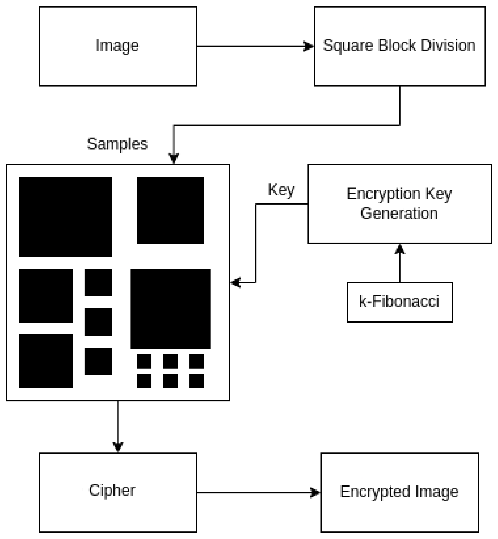
The basic steps of the proposed SBD-Fibonacci algorithm for image encryption are the following: (1) Square Block Division (SBD). The input image is divided into non-overlapping square blocks of varying sizes (
Section 4.1). (2) Optimization using Lagrange Four-Square Theorem. To minimize the number of vulnerable small blocks (
or
), the Lagrange Four-Square theorem is applied. This technique merges multiple small blocks into larger, more secure blocks (
Section 4.2). (3) Master Key Generation: A master key consisting of a list of randomly generated integer values is created providing the basis for the construction of encryption keys for all individual blocks (
Section 4.3). (4) Encryption Key Construction. This step is applied to each square block. Specifically, if the block size is greater than 2 × 2, a generalized Fibonacci matrix is generated and modified using the master key. Otherwise, a simple multiplication with a master key element is applied (
Section 4.3). (5) Block-wise Encryption. Each block is encrypted individually using its corresponding key matrix (
Section 4.3). (6) Cipher Image Assembly. The encrypted blocks are recombined to form the final encrypted image (
Section 4.3).
4.1. Square Block Division (SBD)
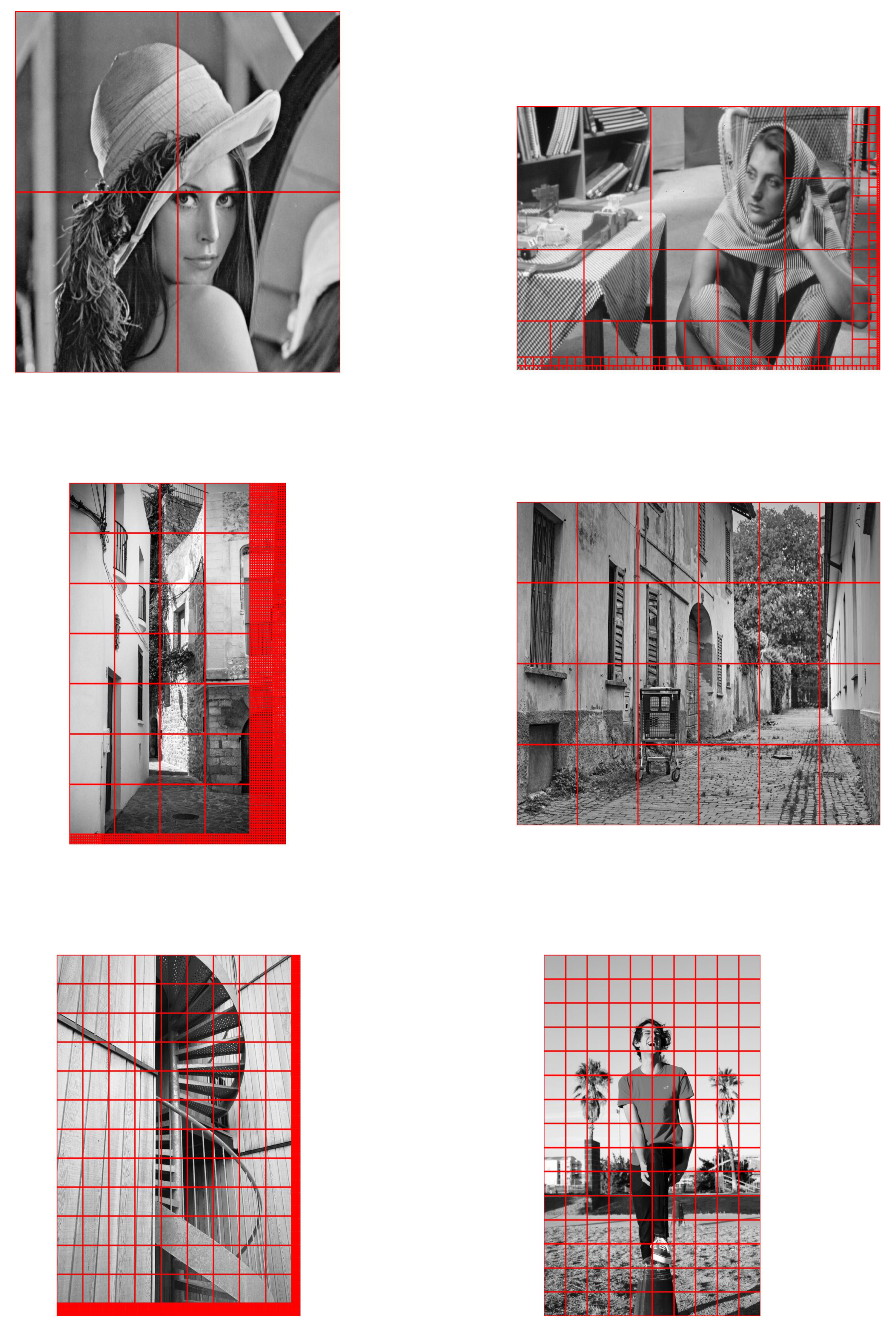
In this subsection, we present a novel division scheme that divides the entire image into square blocks of different sizes, which will also be called samples. To the best of our knowledge, this is the first time such an approach has been presented and also applied in image cryptography. Algorithm 1 demonstrates the division process of the SBD-Fibonacci algorithm in a top-down approach.
| Algorithm 1 Square Block Division Algorithm |
| Input:
|
| Output: list of square blocks, |
- 1:
, - 2:
- 3:
for to 1 do - 4:
, - 5:
- 6:
for to m step x do - 7:
for to n step x do - 8:
createBlock(i,j,x) - 9:
end for - 10:
end for - 11:
if then - 12:
for to step x do - 13:
for to n step x do - 14:
createBlock(i,j,x) - 15:
end for - 16:
end for - 17:
for to m step x do - 18:
for to step x do - 19:
createBlock(i,j,x) - 20:
end for - 21:
end for - 22:
end if - 23:
end for - 24:
return
|
The algorithm requires four inputs. The variables
m and
n represent the total number of rows and columns of the image, respectively. The division is performed iteratively (lines 3–23), starting with large sample sizes and gradually reducing the sample sizes based on the next two input parameters: the base size
b and the number of divisions
p. At each iteration, the algorithm attempts to fit as many square blocks of size
as possible within the remaining undivided areas. This ensures the efficient handling of large images with varying dimensions. To select the optimal values of
b and
p for a given image, an optimization process is employed and presented in
Section 5. The goal is to minimize the number of single-pixel or very small blocks, as they may pose vulnerabilities in the encryption strength. The optimization is based on a heuristic that analyzes how different choices of
b and
p impact the fragmentation of the image, seeking combinations that reduce the number of isolated pixels. The outer for loop (line 3) is executed
p times and in each iteration, one or more square blocks of size
are generated with
,
, starting with
blocks and gradually reducing to
. After the division process, the maximum size of the blocks will be
, while the minimum size will be
(if any). Note that not all iterations will result in square blocks, as the current block size,
, may exceed the remaining dimensions of the undivided image.
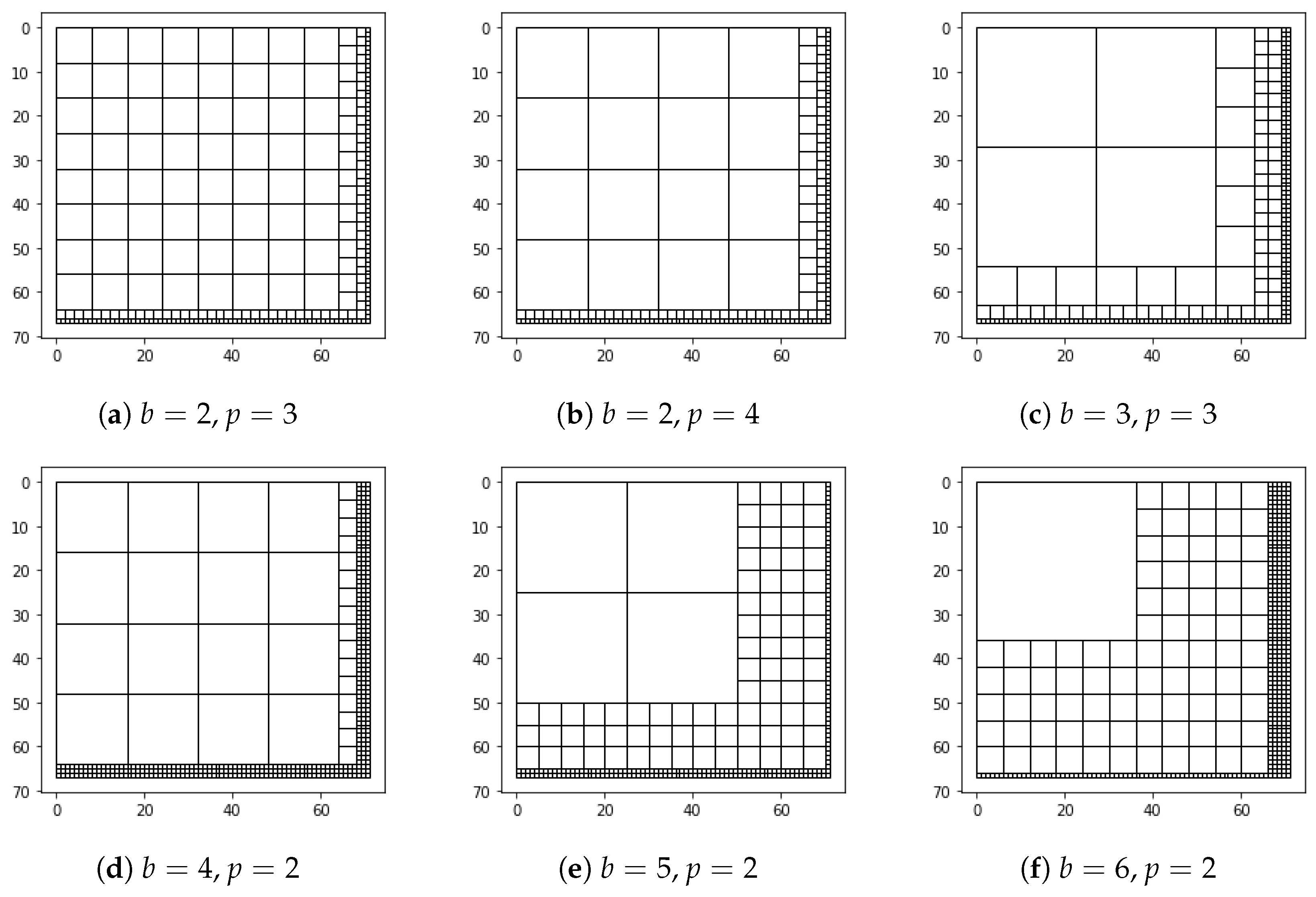
In
Figure 2, we use a
sample image to illustrate different scenarios of square block division when varying
b and
p values.
Table 2 displays the total number and size of the square blocks generated for each combination. Note that these small image dimensions of prime numbers are employed solely for demonstration purposes. In more practical scenarios, image dimensions are larger and more efficient, and
b and
p values need to be selected in a way that prevents the formulation of numerous instances of
blocks. Therefore, the optimization process described in
Section 5 is initially performed to determine the best combination of
b and
p. These optimized values are then used as inputs in SBD.
Variables and represent the maximum row and column value encountered during each division step, respectively. They are updated within the algorithm when a new division iteration is initiated (line 4). These variables play an important role in the proposed algorithm as they are used to keep track of the current maximum row and column offsets from the previous square block division. As a result, the subsequent iterations of the algorithm will only focus on the remaining undivided parts of the image, eliminating redundant checks on the previously divided sections. This optimization leads to significant gains in the overall execution runtime of the algorithm.
The purpose of the inner loops is to perform the necessary divisions in the image (lines 6–10, 12–16, and 17–21). Their operation is similar, however by varying their ranges and step sizes, different parts of the same image are considered for division. In the first iteration of the outer loop both
and
are set to zero and the inner nested loop (lines 6–10) iterates over the entire image with a step size of
x. In this way, the image is divided into
blocks, with
being the maximum accepted size. In the subsequent iterations, when the if condition of line 11 is true, all three nested for loops are executed and examine different undivided portions of the image. The third inner loop (lines 17, 18) iterates over the bottom-left part of the image, the second inner loop (line 12, 13) iterates over the top-right part, while the first inner loop (line 6, 7) iterates over the remaining image.
| Algorithm 2 Function createBlock |
| Input:
|
- 1:
if && then - 2:
- 3:
push s into - 4:
if then - 5:
- 6:
end if - 7:
if then - 8:
- 9:
end if - 10:
end if - 11:
Update
|
The createBlock function is an essential component of the SBD algorithm, being called within a nested loop structure to execute specific tasks during each iteration of the division process. This function serves three main purposes: block creation, list appending and updating maximum cut dimensions. We consider each square block as a tuple of four elements: , where r and c represent the row and column position (index) of the block within the image, ℓ describes the length of the block and is an sub-image of P that contains a sample from the plaintext from row and column. The algorithm starts with an empty list (Algorithm 1, line 2) and progressively appends square blocks (Algorithm 2, line 3) into . Line 1 in Algorithm 2 guarantees that block dimensions do not exceed image boundaries. Through lines 4–9 in Algorithm 2, variables and keep track of the maximum row and column value encountered during the creation of a new square block.
4.3. Key Generation and Encryption
The proposed SBD-Fibonacci algorithm illustrates the encryption process and generates the required key matrix. Its input is the list
, which consists of the square blocks,
s, produced by SBD and represents the plaintext
P.
| Algorithm 4 Key_Generation function |
| Input: |
| Output: Encryption key, K |
- 1:
for to step d do - 2:
for to do - 3:
- 4:
- 5:
end for - 6:
end for - 7:
return as K
|
In order to encrypt and decrypt the divided image, a simple solution could be to create and store a different key,
K, for each block
s. However, this would require an undefined number of unique keys and would create significant implications for key management. Instead, to avoid that, the algorithm starts by generating a master key
L, which is a list of randomly selected integers within the range
with length
. Algorithm 4 is implemented to incorporate
L into each
K corresponding to a block
s with
.
| Algorithm 5 SBD-Fibonacci Algorithm |
| Input: |
| Output: Encrypted image, E |
- 1:
- 2:
generate list L - 3:
- 4:
for each s∈ do - 5:
if
then - 6:
- 7:
- 8:
end if - 9:
end for - 10:
Convert square blocks of into a vector, - 11:
- 12:
Generate Square Blocks from - 13:
Append new Square Blocks into - 14:
for each do - 15:
if
then - 16:
Reuse elements if is exceeded - 17:
end if - 18:
if
then - 19:
- 20:
- 21:
- 22:
else - 23:
if then SD() s.t else - 24:
- 25:
- 26:
- 27:
- 28:
- 29:
end if - 30:
place e into E - 31:
each for - 32:
return
E
|
The master key L serves as the foundation for constructing the encryption keys for each block. For blocks with , the key generation process involves several steps to ensure the security and uniqueness of each block’s key matrix. Initially, a generalized Fibonacci matrix Q is generated based on randomly selected parameters. This matrix is then expanded using the direct sum operation to match the size of the block. Specifically, the direct sum is created, where is the ratio of the block size to the smallest divisor d of the block size. The elements in the first row of each Q in the direct sum are replaced with the values from the master key L, except for the rightmost element, which remains fixed at one. This ensures that the resulting key matrix K is always invertible. The key matrix K is then raised to the power of d to construct the final encryption key for the block.
A detailed description of the key generation process and encryption scheme is provided in the following paragraphs.
Algorithm 5 examines each block s contained in in an iterative fashion. As previously mentioned, the SBD process generates square blocks of various sizes , with a minimum of pixel. However, multiple blocks with can lead to security breaches and put the encryption process at risk. To address this issue and strengthen the encryption, we employ the Lagrange Four-Square theorem, as explained in the relevant subsection. Hence, the and single-pixel blocks are excluded from the main list and stored separately in a vector, called (lines 4–9). Then, Algorithm 3 is applied to the length of the vector to return a list, , of four nonnegative integers (line 11). The positive integers in will determine the size of at most four new square image blocks that will be added to (lines 12–13). Note that this process can still create and blocks, but now their number is reduced to a maximum of four, thus making the encryption process more robust.
The key generation and encryption processes are carried out between lines 14 and 31. Lines 18–21 involve multiplying a single pixel
s with an element from the master key
L, which represents the encryption key
K. Once the multiplication is completed, the encrypted block,
e, is created using the modulo-256 operation ensuring its value remains within the permissible pixel range. Alternatively, when the block
s has
we proceed as outlined in lines 23–28. The following steps are conducted for key generation. Initially, we calculate the smallest divisor
of
that is greater than or equal to 3, otherwise, we set
(line 23). Then, a random
generalized Fibonacci matrix
Q is considered as defined in Equation (
3). This matrix is later enlarged to define the direct sum
as in Equation (
5) of
generalized Fibonacci matrices, where
is the ratio of
to
d (lines 24–25). This operation ensures that the size of the key matrix will be compatible with the dimensions of the sample to be encrypted. Afterwards, Algorithm 4 is executed to replace the
elements in the first row of every matrix
Q in
with entries from the list
L and return the direct sum
(line 26). The resulting direct sum consisting now of
different Fibonacci matrices is raised to the power of
d to construct the encryption key
(line 27). Throughout the procedure, it should be noted that all elements within the first row of
,
, have changed, except for the rightmost element, which is fixed at a value of one. This fact, combined with the discussion presented in
Section 3 and Equation (
8), guarantees that the matrix
K is always invertible and satisfies Equation (
9). Then, the key matrix
K is multiplied by the sample and the modulo 256 operation is performed (line 28).
It is important to note that if the number of elements of L, which are used in the key generating process, exceeds 256, then those elements are reused according to lines 15–17 of Algorithm 5. The algorithm then combines all the encrypted blocks into an image that has the same dimensions as the original image P. This process leads to the encrypted image E and occurs between lines 30 and 32.


 ,
, 


