Article

Efficient Phase-Field Modeling of Quasi-Static and Dynamic Crack Propagation Under Mechanical and Thermal Loadings

1
Department of Mechanical Engineering, College of Engineering, University of Ha’il, Ha’il City 81451, Saudi Arabia
2
Laboratory of Mechanics Modeling and Production, National Engineering School of Sfax, University of Sfax, Sfax 3038, Tunisia
3
Higher School of Sciences and Technologies of Hammam Sousse, University of Sousse, Soussse 4023, Tunisia
4
College of Computer Science and Engineering, University of Ha’il, Ha’il City 81451, Saudi Arabia
*
Author to whom correspondence should be addressed.
Mathematics 2025, 13(11), 1742; https://doi.org/10.3390/math13111742
Submission received: 28 April 2025 / Revised: 18 May 2025 / Accepted: 22 May 2025 / Published: 24 May 2025
(This article belongs to the Special Issue Scientific Computing for Phase-Field Models)

Abstract

The main objective of this work was to model the failure mechanisms of brittle materials subjected to thermal and mechanical loads. A diffusive representation of the crack topology provides the basis for the regularized kinematic framework used. With a smooth transition from the undamaged to the fully damaged state, the fracture surface was roughly represented as a diffusive field. By integrating a staggered scheme and spectral decomposition, the variational formulation was used after being mathematically written and developed. Its effectiveness was analyzed using extensive benchmark tests, demonstrating the effectiveness of the phase-field model in modeling the behavior of brittle materials. This proposed approach was experimentally tested through the examination of crack propagation paths in brittle materials that were subjected to variable mechanical and thermal loads. This work focused on the integration of a spectral decomposition-based phase-field model with thermo-mechanical coupling for dynamic fracture, supported by benchmark validation and the comparative assessment of energy decomposition strategies. The results highlight the accuracy and robustness of numerical and experimental methodologies proposed to model fracture mechanics in brittle materials subjected to complex loading conditions.

1. Introduction

Analysis of material behavior and damage mechanics is a complex challenge in industrial applications. Numerical and experimental analyses have been carried out to understand the damage mechanisms of various materials, and thus improve their performance and reliability in engineering applications [1,2,3]. The finite element method (FEM) has become increasingly crucial in the prediction of the damage mechanisms of various materials, helping to reduce costs in an industrial context. Researchers are able to analyze material stresses, crack propagation, and failure modes using numerical simulations of material behavior under different loading conditions, within the framework of the FE method [4,5]. FEM represents cracks as discrete discontinuities, which poses significant difficulty when the material features complex or unknown crack patterns. To overcome these limitations, advanced numerical techniques, such as phase-field modeling, have been developed [6,7]. During this approach, the fracture surface is approximated by a diffusive field, thus approximating the sharp crack discontinuity. It consists of incorporating a continuous damage field, which is a smeared illustration of the crack. This approach relies on a regularized function approximating the Griffith energy [8]. This regularization converges with the Griffith failure model. Various decomposition methods have been proposed in the literature. These approaches were established in order to decompose the strain energy in a way descriptive of the behavior of cracked components. The stain energy in the stored part is separated from the energy, which contributes to the propagation of the cracks. The deviatoric and volumetric quantities of the strain tensor are decomposed [9]. Indeed, only two parts contribute to the fracture: the deviatoric and the positive volumetric quantities. Other methods use spectral decomposition techniques, wherein only the part related to the positive eigenvalues of the strain tensor contributes to the propagation of the cracks [10]. A newer, similar decomposition method is applied to the stress tensor instead of the strain and is applicable to anisotropic elastic problems [11,12]. The performance of each decomposition method has been analyzed for quasi-static and dynamic fracture examples [13,14].
The phase-field approach exhibits excellent prediction abilities in multi-physics fracture problems. In fact, Miehe et al. [15] focused on thermo-mechanical coupling, modeling diffusive cracks with gradient damage theory and capturing heat conduction and crack face interactions. Miehe et al. [16] extended their work to fluid- and moisture-driven fractures in porous media, integrating hydro-poro-elasticity, fluid flow in cracks, and effective stress criteria. Both approaches emphasized modularity, overcoming challenges in simulating complex crack topologies, and were implemented using robust finite element methods for various fracture scenarios. Clavijo et al. [17] used the phase-field approach in a coupled hydro-chemo-mechanical model to simulate fracture propagation in chemically active rock formations. The developed model revealed that chemical processes accelerate mechanical failure by inducing porosity changes and rock weakening, enhancing fracture development. Qi and Pi [18] integrated the phase-field method to analyze the crack inclination, position, and gradient index for functional gradient material (FGM). Through experiments, this approach offers valuable tools for FGM service life estimation and structural optimization. The proposed fracture model has also been used in the simulation of crack evolution in brittle materials subjected to thermal shock [19,20,21]. The researchers developed a thermo-mechanical phase-field model to study crack propagation under thermal shock. It couples heat transfer, elastic deformation, and fracture, reproducing experimental crack paths. Indeed, the crack pattern creation under thermal shock is complicated and rapid. This development is hard to capture experimentally. Only the final crack patterns are easily observable, which is why numerical simulations are valuable for replicating this cracking process. Recently, a phase-field model has been developed to compute ductile fractures [22,23] and the matching thermal coupling effects [24]. In addition, there has been a growing interest in employing phase-field models to study the dynamic fracture behaviors of materials subjected to varying loading conditions [25,26,27]. These models provide insights into material responses under dynamic loading, where, at lower rates, they approximate quasi-static behaviors, and, at higher rates, inertia effects introduce complexities, such as increased stiffness and intricate crack propagation [28,29]. Researchers have explored dynamic crack branching in homogeneous materials [30], emphasizing the necessity for accurate dynamic models for rapid fracture events. Furthermore, studies have extended phase-field approaches to simulate crack propagation and branching in functionally graded materials (FGMs) under impact conditions [31] and have further developed formulations to model dynamic ductile fracture in elastoplastic composites, incorporating phenomena like interfacial debonding [32].
As a synthesis, the phase-field approach is a promising and evolving framework that requires further development, particularly in addressing the validation of experimentally observed crack patterns. This is especially relevant for dynamic and thermo-mechanical coupling problems, where the method’s predictive capabilities can significantly enhance the understanding of fracture processes in complex systems. In this context, a mechanical phase-field model is developed in this paper to analyze crack patterns in brittle materials in quasi-static and dynamic conditions. The efficiency of the spectral decomposition method, combined with a staggered scheme, is demonstrated through benchmark tests. Building on this, a thermo-mechanical combined phase-field model is established to predict diverse dynamic crack patterns under thermal shock. The model incorporates a phase-field variable to effectively couple heat transfer, deformation, and fracture processes, accounting for the thermal effects on crack propagation. Numerical examples are provided to highlight the advantage of this model, which accurately captures realistic crack patterns in brittle materials.

2. Report on Phase-Field Approach Modeling Mechanical Problems

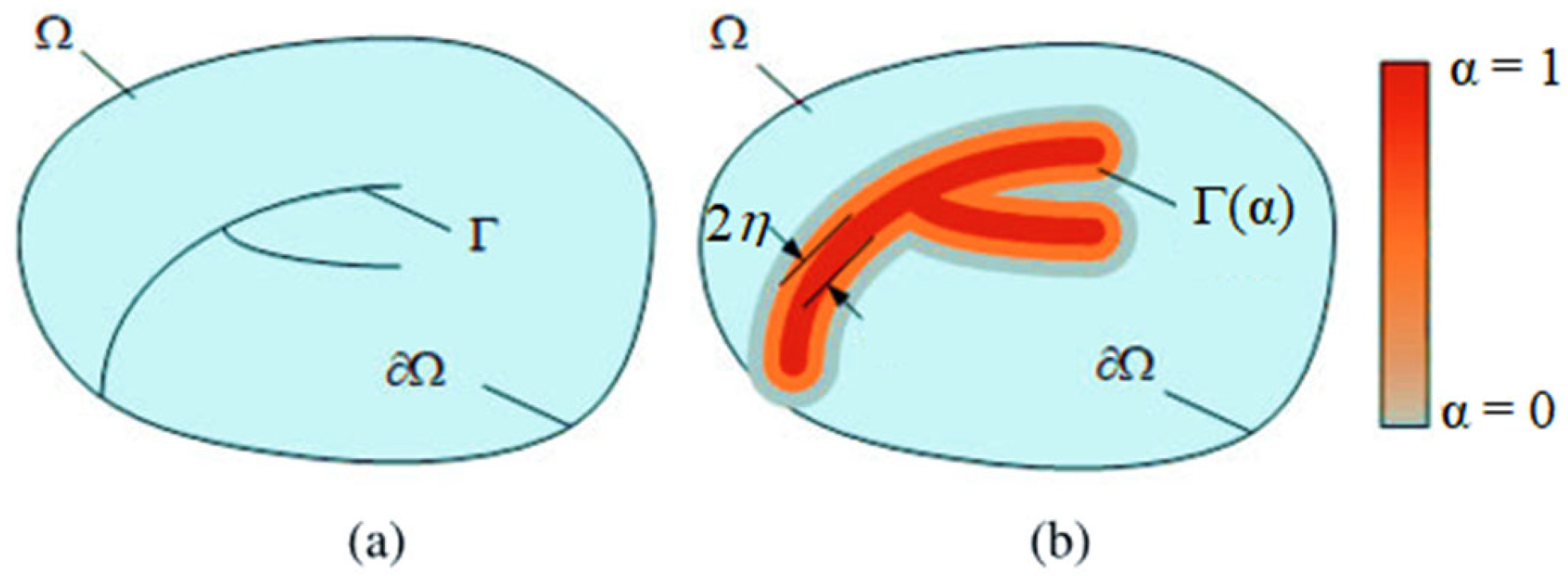
2.1. Phase-Field Approach

The phase-field model is a numerical approach that has gained significant interest from engineering researchers investigating fracture mechanisms. Recently, extensive works on phase-field models have demonstrated their remarkable ability to replicate complex crack patterns by substituting sharp discontinuities with a diffusive damage field. Indeed, by introducing the continuous damage field denoted α, the phase-field model removes the need for prior knowledge of crack paths and smooths displacement discontinuities along cracked surfaces, effectively removing crack tip singularities. This capability makes the phase-field model a powerful tool for simulating complex fracture processes in diverse loading conditions.
Consider a solid Ω containing an internal discontinuity represented by a discrete crack zone Γ and an external boundary ∂Ω (see Figure 1a). We model the damage zone Γ using the diffusive damage field α (illustrated in Figure 1b), where α = 0 outside the crack and α = 1 within the cracked region.
The regularization parameter typically refers to the length scale parameter, denoted 2η. This parameter controls the width of the diffuse crack interface and ensures the smooth transition between intact and fully fractured states. The discrete crack zone Γ is regularized by the diffusive damage field as follows:
Γ = Ω γ   α , α d V with   γ   α , α = α 2 2 η + η α 2 2 ,
Our approach employs the spectral decomposition method to analyze the degradation of stiffness, as defined in the strain energy term, during crack evolution. By applying the alternate minimization principle, we determine the displacement field U(x,t) and the damage field α(x,t) in the domain Ω.
U : Ω × T i m e   R 3 ( x , t )   U ( x , t ) and   α : Ω × T i m e   0 , 1 ( x , t )   α ( x , t ) ,
The staggered (or alternate minimization) scheme is employed to solve the coupled displacement and phase-field equations. This approach decouples the system into two subproblems, which are the mechanical equilibrium and the phase-field evolution. They are solved sequentially at each time step. In fact, we solve the mechanical equilibrium equation for the displacement field using the current damage field, and then we update the phase-field variable by solving the corresponding evolution equation using the updated displacement field. Once convergence is achieved, the algorithm proceeds to the next loading increment.
Under the small displacement assumption, the elastic energy density, denoted Wel, within the variational context is given by Equation (3). We designate the isotropic elasticity and the symmetric elastic strain tensors respectively _ ¯ and ε _ U .
W e l = 1 2 1 α 2 _ ¯ ε _ U . ε _ U ,
where _ ¯ is the isotropic elasticity tensor and ε _ U is the Cauchy strain tensor. This definition applies to arbitrary admissible displacement and damage fields, capturing the relationship between elastic deformation and stiffness degradation. The stress tensor is illustrated by Equation (4).
σ ¯ = 1 α 2 _ ¯ ε _ U ,
In addition, the fracture energy density (Equation (5)) is related to the critical energy release rate (Gc), which represents the material’s fracture toughness. It is distributed over the regularized crack phase-field.
W α α , α = G c   γ α , α ,
The mechanical energy, E(U,α), associated with an isotropic crack topology is expressed by Equation (6). This energy formulation shows the interaction between the displacement field and the damage phase-field. It represents the sum of the elastic energy and the deformation energy associated with crack propagation, providing a comprehensive description of the strain energy contributions and the material degradation effects due to evolving cracks.
E ( U , α ) = Ω / Γ W e l ε , α d x + Γ W α α , α d Γ ,
In order to compute the crack nucleation and propagation, the staggered scheme is used, which divides the problem into two subproblems that are solved iteratively. In this scheme, the displacement field and the damage phase-field variable are alternately updated by minimizing the mechanical energy (Equation (6)) with respect to each variable while keeping the other fixed. Furthermore, Newton-Raphson iterations are integrated into the staggered scheme to enhance its numerical stability and convergence efficiency. The Newton-Raphson method ensures robust solutions by iteratively linearizing and solving the non-linear equations arising from the energy minimization process. This combination of the staggered scheme and Newton-Raphson iterations allows for a stable and efficient simulation of crack evolution, capturing both the initiation and propagation phases with high accuracy.

2.2. Spectral Decomposition Method

The evolution of the crack phase-field occurs solely under conditions of tensile elastic energy, designed Ψ + . This condition is applied by decomposing elastic energy into tensile and compressive components. We denote ε+ and ε as the positive and negative components of the strain, respectively. The tensile elastic energy is given by Equation (7).
Ψ ± ( ε ) = λ 2 tr   ε ± 2 + μ   ε ± 2 ;   X ± : = 1 2 X   ±   X   and   ε ± : = i = 1 3 ε i ± N i N i
where ε i i = 1 3 and N i i = 1 3 are the principal strain components and directions, respectively.
Using the spectral decomposition method, the elastic energy density is separated into tensile (positive) and compressive (negative) components. This decomposition is essential for accurately modeling crack propagation, as cracks predominantly grow under tensile stresses, while compressive stresses tend to inhibit crack growth by closing the crack faces. In this framework, the damage degradation function is applied exclusively to the tensile component of the elastic energy density (Equation (8)). This ensures that the damage, represented by the phase-field variable, reduces the material’s stiffness only in regions experiencing tensile stress. The compressive component remains unaffected by the degradation function, preserving the material’s ability to resist compression.
W e l ε , α = 1 α 2 Ψ + ε + Ψ ε
The variational formulations (Equations (9) and (10)) of the displacement and damage subproblems, using the spectral decomposition method, are as follows.
Ω 1 α 2 σ + : ε δ U d x + Ω σ : ε δ U d x = 0
Ω 2 1 α H + δ α + G c η α δ α + η 2 α δ α d x = 0
The staggered scheme offers improved numerical stability and efficiency, particularly for problems involving strongly nonlinear fracture behavior. The crack driving force, H, is introduced in the phase-field fracture model to enforce the irreversibility of the phase-field evolution. Irreversibility ensures that once a crack has formed (α increases), it cannot heal (α decreases), reflecting the physical reality of fracture processes in materials. As shown in Equation (11), it is defined as the maximum value of the tensile elastic energy density during the deformation history.
H + = m a x t 0 , T Ψ + U x , t 0

2.3. Dynamic Fracture Approach

In dynamic fracture simulations, determination of the mass and stiffness matrices is crucial for accurately modeling the nucleation and the dynamic crack propagation. The mass matrix typically represents the inertial effects, accounting for the mass distribution and acceleration of the system. However, the stiffness matrix quantifies the resistance of the materials to deformation or fracture under applied loads. We define M as the mass matrix, K as the stiffness one, and f(t) as the applied load. Damping effects are ignored in the dynamic fracture process. Time integration in this simulation is performed using the Newmark method [33], which is used for solving Equation (12). We select the parameters β = 0.25 and γ = 0.5 to ensure the stability and accuracy of the Newmark algorithm [34].
M 2 U t 2 + K U = f ( t )
The kinetic energy density (Equation (13)), which is not dependent on the phase-field variable, is added to the expression of mechanical energy.
W k i n = 1 2 ρ U t 2
where ρ is the material density. Equation (13) captures the kinetic energy per unit volume of the material, reflecting how the motion of the material influences crack propagation dynamics in the phase-field model framework. The body forces are assumed negligible. Then, the phase-field problem using the spectral decomposition in a dynamic loading condition is expressed as follows:
σ x = ρ   2 U t 2 4 η 2 Δ α + α = 4 η G c 1 α H + i f   Ψ 0 + < Ψ 0   α = 0

3. Results of the Mechanical Model

In this section, three numerical samples are presented to assess the modeling capabilities of the investigated phase-field method using a staggered schema and spectral decomposition method under both quasi-static and dynamic loading conditions. The length scale parameter is 2η = 0.01 mm. A refined finite element mesh was employed along the crack growth path, with a minimum mesh size of h = 0.002 mm.
The first example examines a rectangular plate subjected to tension, evaluating its response under both quasi-static and dynamic loading scenarios. The numerical simulations demonstrate a strong agreement with experimental observations, particularly in terms of crack patterns. The numerical simulations reveal distinct crack patterns between quasi-static and dynamic loading conditions, consistent with experimental observations. Additionally, the influence of geometric parameters is thoroughly investigated and compared with the existing literature. The second example involves a square plate subjected to shear loading conditions. Numerical simulations closely matched numerical results from the literature in terms of evolving crack patterns. The effectiveness of spectral decomposition in predicting shear behaviors was highlighted and compared with findings from existing studies. The third example examines dynamic crack propagation under mixed-mode loading. The specimen is designed and impacted by a fast jack equal to V = 10 m/s. It contains a hole and an initial notch. The study highlights the spectral decomposition method’s effectiveness in predicting crack patterns, with numerical results validated experimentally.
These setups have been extensively studied in the existing literature, with some experimental solutions available for quasi-static loading conditions, while data for dynamic loading conditions are rare.

3.1. Tensile Test of Notched Pieces

Tensile tests are conducted, incorporating both experimental and numerical analyses under quasi-static and dynamic loading conditions. A displacement load along the vertical direction is applied at the upper edge of the specimen, while a displacement constraint is applied at its lower right edge. The material parameters are as follows: Young’s modulus E = 250 KN/mm2, Poisson’s ratio ν = 0.3, and fracture toughness Gc = 0.003 KN/mm. Plane strain conditions were assumed in the numerical model. Figure 2 presents a comparison of the crack growth paths between numerical simulations and experimental results.
The experimental and numerical comparisons presented in Figure 2 provide a detailed analysis of the behavior of notched specimens under both quasi-static and dynamic loading conditions. In numerical and experimental tests, the applied loading speed of 10 mm/min indicated quasi-static loading conditions, as it was only a small fraction of the Rayleigh wave speed. At this slow speed, dynamic effects are negligible. However, when the loading speed exceeds 1 m/s, the conditions are no longer quasi-static, and dynamic effects become significant, influencing stress distribution and affecting crack patterns. This distinction between quasi-static and dynamic loading is crucial for understanding material behavior under different conditions. Figure 2b illustrates tensile test results, under quasi-static loading, for a specimen with dimensions D = 5 mm and b = 4 mm. Figure 2c investigates the influence of hole-to-notch distance, showing that varying this distance (e.g., D = 5 mm and b = 8 mm) does not significantly alter the crack path. Both experimental and numerical results indicate a consistent crack propagation trajectory, suggesting minimal impact from the presence of the hole on stress concentrations. These tests show close agreement between numerical simulations and experimental data. This validation confirms the reliability of the numerical model in capturing material response and crack propagation under quasi-static conditions. Furthermore, Figure 2d,e explore larger hole diameters (e.g., D = 10 mm with b = 5 mm in (d) and b = 6.5 mm in (e)). Crack initiation and propagation align with observations under quasi-static loading. The same phenomenon has also been observed in other studies from the literature [35,36]. This reinforces the robustness of the applied fracture model across different geometrical configurations.
Under dynamic loading conditions, described in Figure 2f,g, the behavior deviates significantly. At lower speeds (V = 1 m/s), cracks tend to propagate linearly with slight deviation towards the hole, indicating a lesser influence of stress concentrations due to the rapid evolution of stress fields. This result is proved experimentally. However, at higher speeds (V = 5 m/s), dynamic effects induce multi-cracking, reflecting the complex interaction of inertia and stress wave propagation. This dynamic fracture behavior leads to unpredictable crack patterns, contrasting suddenly with the more uniform paths observed under quasi-static conditions. Then, in the quasi-static case, our model demonstrates strong consistency with findings from existing literature [37,38]. Moreover, the results of the dynamic numerical tests show good agreement with experimental observations, further validating the accuracy of the proposed approach. In summary, this study confirms the reliability of numerical simulations in predicting fracture behavior across various geometries, material properties, and load speeds.

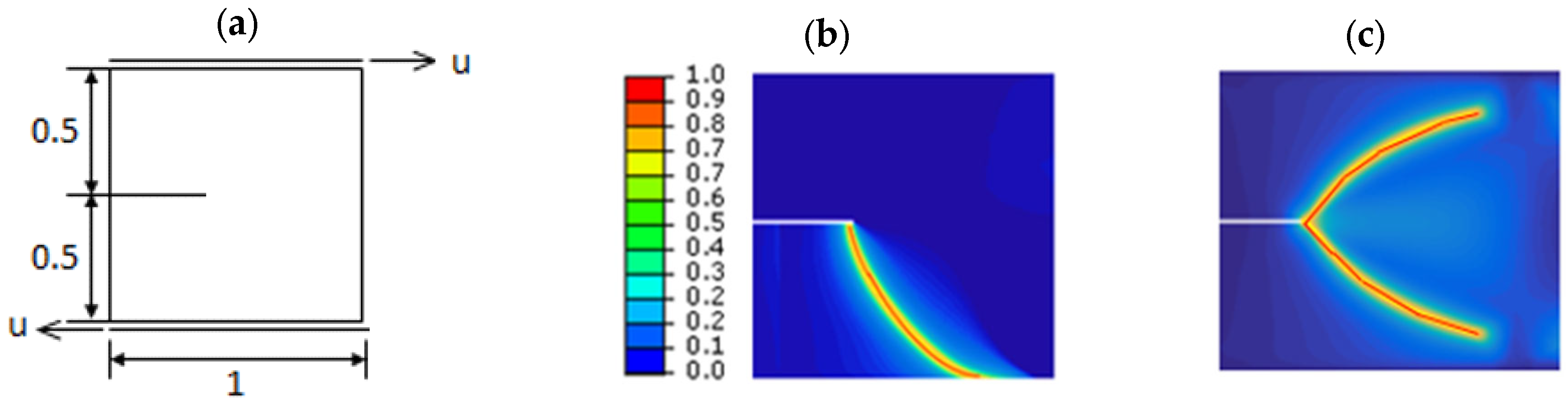
3.2. Shear Test of Notched Pieces

A shear test was conducted, incorporating numerical analysis under quasi-static loading conditions. A shear load was applied along the top boundary. The material parameters used in the analysis were as follows: Young’s modulus = 120 kN/mm2, Poisson’s ratio ν = 0.3, and fracture toughness Gc = 0.001 kN/mm. Schematic of notched specimen using the two methods is plotted if Figure 3.
For the decomposition of the deviatoric strain method, two symmetric crack branches were formed, as reported in [14,35,36]. This is because the associated formulation allows cracking in the compressed regions. For that, this decomposition governs crack propagation along the upper crack path, reflecting the material’s response to deviatoric stress. In contrast, crack formation along the lower path is predominantly driven by tensile stresses, making it a more physically realistic phenomenon as it aligns with the intrinsic behavior of materials under tensile loading. Then, the spectral decomposition method differentiates tensile and compressive effects and ensures a physically consistent representation of crack propagation, making it ideal for simulating true material failure.
In summary, the spectral decomposition method is more suitable for problems involving mixed-mode loading or compressive-shear loading. This is because it separates the strain energy into tensile and compressive parts, and only the tensile part is degraded during damage evolution. As a result, it prevents unphysical damage under compression, which aligns better with real fracture behavior. However, the main limitation of this method is its higher computational cost, since it requires calculating the eigenvalues of the strain tensor. On the other hand, the deviatoric strain decomposition method is easier to implement and computationally faster, making it attractive for large-scale simulations or preliminary studies. Nevertheless, this method degrades the entire deviatoric part of the strain energy, including compressive contributions. This can lead to overestimation of damage in zones dominated by shear or compression and sometimes results in non-physical crack patterns under such loading conditions.

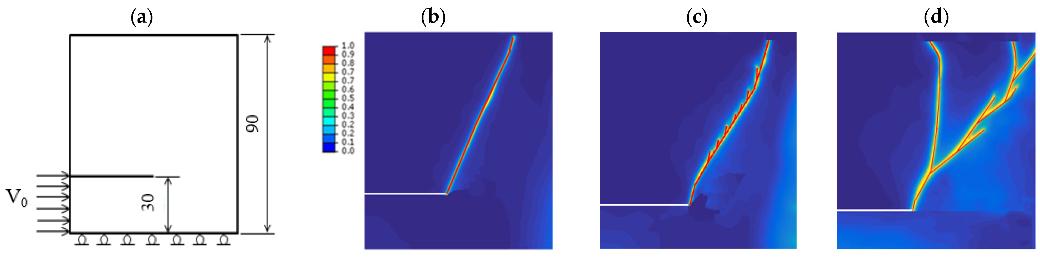
3.3. Mixed-Mode Loading Tests of Notched Pieces

A compression test with higher impact velocity was conducted, incorporating both experimental and numerical analyses. The material parameters used in the analysis were as follows: Young’s modulus E = 2.9 KN/mm2, Poisson’s coefficient ν = 0.35, and fracture toughness Gc = 0.194 KN/mm. Figure 4 presents the comparison between experimental and numerical results of crack propagation in the presence of notches. To simulate dynamic loading conditions, a loading velocity of V = 10 m/s is applied.
The main goal of these tests is to compare our numerical results obtained using the spectral decomposition method with the experimental ones reported by Grégoire [39]. In fact, Figure 4b compares the experimental and numerical results of crack propagation in a notched specimen submitted under dynamic loading conditions. The numerical model accurately captures the crack path, demonstrating deviation and eventual crack arrest. A good correlation is observed between the experimental and numerical results, as both exhibit crack deviation and arrest, validating the predictive accuracy of the numerical model. For the double-notched specimen (Figure 4d), the crack path is influenced by the presence of the second circular notch, leading to deviation and potential arrest. Initially, the crack follows a straight trajectory but deviates due to the influence of the circular notch before eventually arresting, closely matching the experimental observation. However, a small difference was observed in the crack deviation and crack arrest relative. In the numerical test, the crack deviation occurs earlier, and crack arrest occurs later, to a smaller extent, than in the experimental results. The comparison between the experimental and numerical results proves a good correlation in terms of crack deviation and arrest. The numerical model effectively captures the key phenomena observed in the experiment, validating its accuracy in predicting crack behavior in complex geometries under dynamic loading conditions.
A second numerical test was conducted to investigate the influence of loading velocity on fracture behavior. In this test, a mixed-mode loading scenario was applied to specimens featuring a straight notch. The geometry of the specimen and the boundary/loading conditions are illustrated in Figure 5a. To explore the dynamic effects, three different loading velocities were considered: V0 = 0.5 m/s, V0 = 3 m/s, and V0 = 10 m/s.
The resulting crack propagation patterns for each velocity are presented in Figure 5b–d. These results clearly demonstrate the impact of increasing loading velocity on the complexity of the fracture process.
At lower velocities, crack propagation follows a relatively straight path, while higher velocities lead to more intricate crack trajectories, including signs of crack deflection and branching. This highlights the transition from quasi-static to dynamic fracture regimes and underlines the importance of loading rates in fracture analysis.

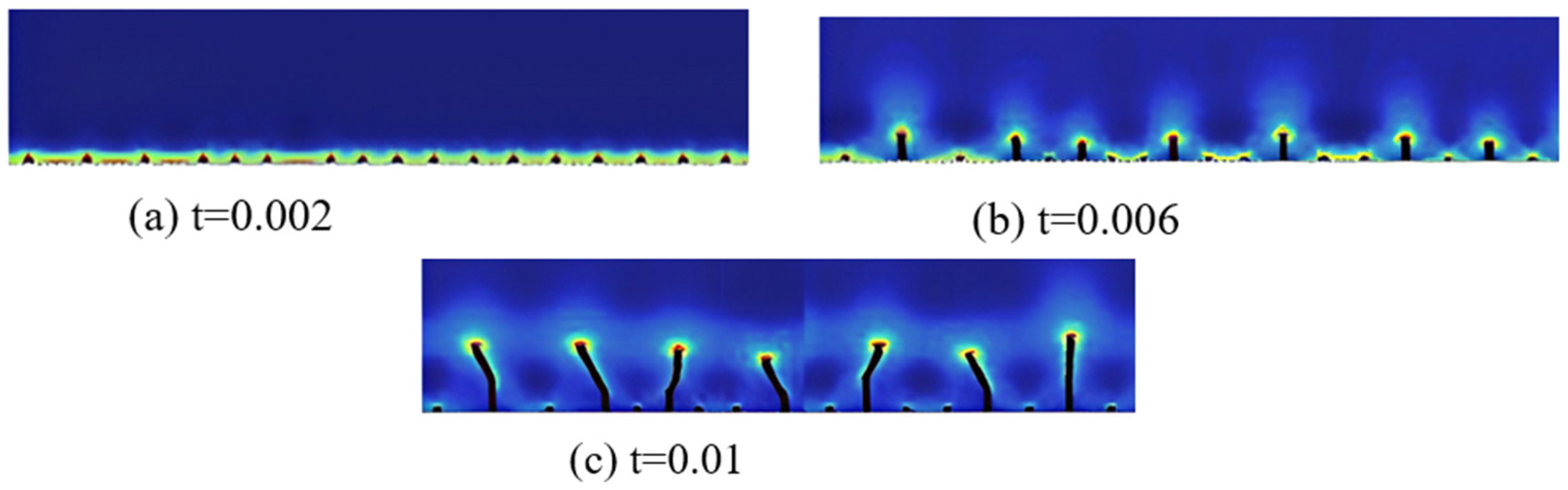
4. Results of the Thermo-Mechanical Phase-Field Framework

The length, L, of the plate (Figure 6) is assumed to be significantly greater than the material’s characteristic length, 2η. This assumption is important for the bifurcation and stability analyses.
As a boundary condition (Equation (15)), there is no stress at the left and right boundaries in both the normal and shear directions. These constraints are then used to solve the mechanical problem.
U x x = L 2 , y = U x x = L 2 , y = 0 σ y x x = L 2 , y = σ y x x = L 2 , y = 0 σ y y x , y = l 2 = σ x y x , y = l 2 = 0
Furthermore, no boundary conditions are imposed on the damage field on the left and right sides, allowing it to evolve freely (Equation (16)). Regarding the initial conditions, the plate is considered to be at a uniform reference temperature, T0, ensuring it remains stress-free and undamaged.
U t ( x ) = 0   ;   ε t e ( x ) = 0   ;   α t ( x ) = 0   ;   σ t ( x ) = 0   ;   x Ω , t 0
Using this model, we can assume that:
  • The temperature field varies only in the x- and y-directions: T = T(x,y,t).
  • The initial temperature is T(x,y,t = 0) = T0.
  • The piece is brought in contact with cold water at temperature T. The water temperature remains constant at T = 20 °C throughout the water quenching test.
  • When the heat penetration depth is much smaller than the length L, a zero-heat flux condition is applied along the lateral and upper edges of the domain. Additionally, it is assumed that the deformation occurs slowly enough to have no impact on the temperature distribution.
The heat conduction equation can be expressed as:
λ   2 T y 2 + 2 T x 2 = ρ   C   T t
where t is the time, λ is the thermal conductivity, and C is specific heat. Based on the heat transfer principles and the boundary conditions at the interface between a solid and a fluid, we obtain the following system.
T x = 0   ;   on   the   y - axis T y = 0   ;   on   the   x - axis λ T x = h T x = L 2 , y , t T   ;   on   AB λ T y = h T x , y = l 2 , t T   ;   on   BC
where h is the convective heat transfer coefficient. In the literature, there is no analytical expression of the variation of temperature and thermal stress fields. It is due to the non-linearity of temperature, which depends on the ceramic’s material properties. However, the numerical thermo-mechanical phase-field model was developed in order to predict crack initiation and crack growth in the thermal shock problem.
The alternate minimization problem consists of solving two coupled sub-problems at each iteration step, as outlined in Equation (19).
( ε , α ) p r o b l e m : ε - problem :   arg min ε E ε ( ε , α , δ ε ) α - problem :   arg min α E α ( ε , α , δ α )
For the ε-problem, the strain field is updated by minimizing the mechanical part of the total energy functional for a fixed damage field. The thermal effects are explicitly incorporated through thermal strains, which directly influence the mechanical response. Once the strain field is updated, the damage phase-field is computed by minimizing the total energy (α-problem). The strain and the damage fields are updated alternately by minimizing the total energy (Equation (20)), allowing the computation of the diverse crack patterns.
E ε u , T , α = ψ 0 ε u ε t h : ε u ε t h d Ω + Γ W α α , α d Γ
where εth is the thermal strain. The thermal effects are thus fully integrated into the mechanical response and the damage evolution through the total energy. In fact, the total energy is minimized in which the thermal expansion coefficient λth is accounted for in the expression of the elastic term as shown as follows:
E e ε u , T = ψ 0 ε u λ t h . T : ε u λ t h . T d Ω
The following Algorithm 1 highlights the sequential steps: starting with the computation of the temperature field, followed by the evaluation of the thermal strain, and finally, the alternate minimization of the total energy with respect to the strain field ε and the phase-field variable α.
Algorithm 1: Numerical implementation of a thermo-mechanical phase-field model
1. Initialization of temperatures
2. Input the material properties and model parameters
3. Provide the loading condition from the previous step: εi−1 and αi−1
4. Compute the temperature field using Equations (17) and (18).
5. Compute the thermal strain.
6. Alternating minimization of the total energy Equation (20).
7. For each time step ti:
               Solve minimization problem with staggered schema (Equation (19)).
               The iteration continues until both fields satisfy the convergence criteria.
8. Set ti = ti+1
9. End for
The converge criteria is given by the following equations:
ε i ε i 1 ε i < 10 6 α i α i 1 α i < 10 6
This section aims to explore the mechanisms of crack propagation in ceramics under thermal loading. We used the finite element framework based on the thermo-mechanical phase-field model to highlight its effectiveness in predicting crack propagation patterns under such conditions. Table 1 illustrates the thermo-mechanical properties of ceramic.
A ceramic plate of size 25 mm × 5 mm × 1 mm is heated to a temperature T0 equal to 500 °C. After that, the heated specimens are dropped into a cold-water bath of T = 20 °C. We represent, in Figure 6, the damage field (α = 1) obtained by the numerical simulation of a ceramic material submitted to a thermal shock. We represent, in Figure 7, some different steps of the cracking process. The crack growth steps are summarized as follows:
In the first phase, the calculated thermal shock cracks form and expand uniformly, maintaining a constant spacing (a). During this phase, cracks propagate simultaneously and at a rapid rate. Over time, the speed of propagation gradually decreases as the thermal stresses begin to dissipate. As a result, only a limited number of cracks continue to progress, while others stop growing, leading to an increase in crack spacing (b). In subsequent stages, crack growth patterns can be varied to achieve uniform spacing (c). This cycle can be repeated several times until the strain energy generated by thermal stress is insufficient to sustain crack propagation. Simulated crack patterns closely resemble those found in experimental observations [20,40].

5. Discussion

The experimental and numerical results in Figure 2 show that, under quasi-static loading, the crack consistently initiates at the pre-notch and propagates straight toward the hole and then to the specimen edge, regardless of hole position or size, aligning with the literature findings. However, under dynamic loading, fracture behavior changes: at 1 m/s, the crack slightly deviates toward the hole, while at 5 m/s, rapid stress redistribution and inertial effects lead to multiple cracks, reducing the hole’s influence on propagation. Furthermore, unlike the deviatoric strain method, which typically results in symmetric crack branches (Figure 3) due to its formulation allowing cracking in compressed regions, the spectral decomposition method distinguishes between tensile and compressive effects more explicitly. This method effectively differentiates between tensile and compressive components in the analysis of crack growth. By decomposing elastic energy density into positive and negative components, it creates a physically relevant context for predicting the fracture behavior of pieces. Its positive component signifies the energy available to be released during crack nucleation and propagation. In contrast, the negative component reflects the energy stored in the material, which acts against crack initiation and growth. In addition, a good agreement between the numerical and experimental results was found in predicting crack patterns in complex geometries under dynamic loading conditions, as shown in Figure 4. In the same context, a thermo-mechanical phase-field fracture model is established to analyze the dynamic crack patterns under thermal shock loading. The quenching test, used to assess thermal shock resistance, is simulated based on experimental studies on ceramics [41]. The numerical results closely replicate the complex crack patterns observed in experiments, demonstrating strong agreement (Figure 8).
Numerical simulations demonstrate a robust ability to describe the evolution of thermal shock cracks, a phenomenon that poses significant challenges to direct observation in experimental settings. The results reveal that as the thermal shock temperature increases, incipient cracks appear in the interstices of already developed crack levels. This suggests that higher thermal stress conditions create new failure points before existing cracks reach their maximum potential. Notably, while the length of the longest crack continues to increase, other crack levels tend to shorten, indicating a complex interplay between crack growth mechanisms. These phenomena were corroborated by experimental results, lending further credibility to the simulation results.

6. Conclusions

Phase-field modeling of quasi-brittle fracture proves to be a powerful tool for addressing mechanical fracture problems, particularly in complex crack patterns or branched cracks. Among different approaches, the spectral decomposition method combined with the alternate minimization scheme provides more accurate crack pattern predictions. This method effectively differentiates between tensile and compressive effects, ensuring that crack propagation occurs only due to positive strains, leading to a physically consistent representation of fracture mechanics, especially under shear loading conditions.
Through numerical simulations, we demonstrated the effectiveness of this approach in predicting crack patterns under both quasi-static and dynamic loading conditions. Then, they provided a systematic comparison between the spectral and deviatoric decomposition approaches under a shear-dominated regime, highlighting their respective limitations and strengths. These findings align well with experimental observations and the literature results. Furthermore, in the context of thermal shock loading, the thermo-mechanical phase-field model successfully reproduces the periodic crack patterns observed in ceramic materials subjected to high temperatures. The computed crack layout exhibits parallel crack formations, with some cracks continuing to propagate while others are constrained. The numerical results closely match experimental findings, confirming the model’s accuracy and efficiency in predicting thermal cracking behavior.
These results validate the spectral decomposition-based phase-field method as a robust and reliable approach for modeling fractures in brittle and quasi-brittle materials, making it a valuable tool for analyzing complex crack evolution under mechanical and thermal loading conditions. This study contributes to advancing phase-field fracture modeling by offering insights into its comparative performance against deviatoric decomposition methods, particularly under compressive shear conditions, and by demonstrating the successful application of spectral decomposition in a dynamically coupled thermo-mechanical framework.

Author Contributions

Conceptualization, L.B.S. and H.H.; Methodology, L.B.S., H.H. and M.H.; Software, M.T. and A.C.; Investigation, L.B.S., H.H. and S.A.; Data curation, M.T.; Writing—original draft, L.B.S. and S.A.; Writing—review & editing, H.H. and M.H.; Visualization, M.T. and A.C.; Supervision, H.H. and M.H.; Funding acquisition, L.B.S. All authors have read and agreed to the published version of the manuscript.

Funding

This research has been funded by Scientific Research Deanship at University of Ha’il –Saudi Arabia through project number RG-24 006.

Data Availability Statement

The MATLAB R2016a script for the principal program of the numerical model used in this study is not publicly available as it is part of ongoing research, and further developments are being made to enhance its accuracy and applicability. However, the script can be obtained from the corresponding author upon reasonable request at bensaid_rmq@yahoo.fr.

Conflicts of Interest

The authors declare no conflict of interest.

References

  1. Ben Said, L.; Allouch, M.; Wali, M.; Dammak, F. Numerical Formulation of Anisotropic Elastoplastic Behavior Coupled with Damage Model in Forming Processes. Mathematics 2023, 11, 204. [Google Scholar] [CrossRef]
  2. Hammami, C.; Kammoun, N.; Hentati, H.; Ben Amar, M.; Haddar, M. Parametric analysis of the damage characterization tests of aluminum bulk material. J. Mech. Sci. Technol. 2022, 36, 5019–5025. [Google Scholar] [CrossRef]
  3. Ammar, S.; Ben Fraj, B.; Hentati, H.; Saouab, A.; Ben Amar, M.; Haddar, M. Mechanical performances of printed carbon fiber-reinforced PLA and PETG composites. Proc. Inst. Mech. Eng. Part L J. Mater. Des. Appl. 2024, 238, 1488–1499. [Google Scholar] [CrossRef]
  4. Jung, J.; Do, B.C.; Yang, Q.D. Augmented finite-element method for arbitrary cracking and crack interaction in solids under thermo-mechanical loadings. Philos. Trans. A Math. Phys. Eng. Sci. 2016, 374, 20150282. [Google Scholar] [CrossRef]
  5. Ben Said, L.; Hentati, H.; Kamoun, T.; Trabelsi, M. Experimental and Numerical Investigation of Folding Process—Prediction of Folding Force and Springback. Mathematics 2023, 11, 4103. [Google Scholar] [CrossRef]
  6. Bourdin, B.; Francfort, G.A.; Marigo, J.J. Numerical experiments in revisited brittle fracture. J. Mech. Phys. Solids 2000, 48, 797–826. [Google Scholar] [CrossRef]
  7. Bourdin, B.; Francfort, G.A.; Marigo, J.J. The Variational Approach to Fracture. J. Elast. 2008, 91, 5–148. [Google Scholar] [CrossRef]
  8. Griffith, A.A. The phenomena of rupture and flow in solids. Philos. Trans. R. Soc. Lond. Ser. A 1921, 221, 163–198. [Google Scholar]
  9. Amor, H.; Marigo, J.J.; Maurini, C. Regularized formulation of the variational brittle fracture with unilateral contact: Numerical experiments. J. Mech. Phys. Solids 2009, 57, 1209–1229. [Google Scholar] [CrossRef]
  10. Miehe, C.; Hofacker, M.; Welschinger, F. A phase field model for rate-independent crack propagation: Robust algorithmic implementation based on operator splits. Comput. Methods Appl. Mech. Eng. 2010, 199, 2765–2778. [Google Scholar] [CrossRef]
  11. Zhuang, X.; Zhou, S.; Sheng, M.; Li, G. On the hydraulic fracturing in naturally-layered porous media using the phase field method. Eng. Geol. 2020, 266, 105306. [Google Scholar] [CrossRef]
  12. Zhang, S.; Kim, D.U.; Jiang, W.; Tonk, M.R. A phase field model of crack propagation in anisotropic brittle materials with preferred fracture planes. Comput. Mater. Sci. 2021, 193, 110400. [Google Scholar] [CrossRef]
  13. Jeong, H.; Signetti, S.; Han, S.T.; Ryu, S. Phase field modeling of crack propagation under combined shear and tensile loading with hybrid formulation. Comput. Mater. Sci. 2018, 155, 483–492. [Google Scholar] [CrossRef]
  14. Kriaa, Y.; Hentati, H.; Zouari, B. Applying the phase-field approach for brittle fracture prediction: Numerical implementation and experimental validation. Mech. Adv. Mater. Struct. 2022, 29, 828–839. [Google Scholar] [CrossRef]
  15. Miehe, C.; Schänzel, C.L.M.; Ulmer, H. Phase-field modeling of fracture in multiphysics problems. Part I. Balance of crack surface and failure criteria for brittle crack propagation in thermo-elastic solids. Comput. Method. Appl. Mech. 2015, 294, 449–485. [Google Scholar] [CrossRef]
  16. Miehe, C.; Mauthe, S. Phase-field modeling of fracture in multi-physics problems. Part III. Crack driving forces in hydro-poro-elasticity and hydraulic fracturing of fluid-saturated porous media. Comput. Method. Appl. Mech. 2016, 304, 619–655. [Google Scholar] [CrossRef]
  17. Clavijo, S.P.; Addassi, M.; Finkbeiner, T.; Hoteit, H. A coupled phase-field and reactive-transport framework for fracture propagation in poroelastic media. Sci. Rep. 2022, 12, 17819. [Google Scholar] [CrossRef] [PubMed]
  18. Qi, C.; Pi, A.G. Calculation method for brittle fracture of functional gradient materials. Sci. Rep. 2024, 14, 29262. [Google Scholar] [CrossRef]
  19. Chu, D.; Li, X.; Liu, Z. Study the dynamic crack path in brittle material under thermal shock loading by phase field modeling. Int. J. Fract. 2017, 208, 115–130. [Google Scholar] [CrossRef]
  20. Wang, T.; Ye, X.; Liu, Z.; Chu, D.; Zhuang, Z. A phase-field model of thermo-elastic coupled brittle fracture with explicit time integration. Comput. Mech. 2020, 65, 1305–1321. [Google Scholar] [CrossRef]
  21. Pang, Y.; Li, D.; Li, X.; Wang, R.; Ao, X. Phase-Field Simulation of Temperature-Dependent Thermal Shock Fracture of Al2O3/ZrO2 Multilayer Ceramics with Phase Transition Residual Stress. Materials 2023, 16, 734. [Google Scholar] [CrossRef] [PubMed]
  22. Proserpio, D.; Ambati, M.; Loren, L.; De Kiendl, J. Phase-field simulation of ductile fracture in shell structures. Comput. Methods Appl. Mech. Eng. 2021, 385, 1140. [Google Scholar] [CrossRef]
  23. Samaniego, C.; Ulloa, J.; Rodríguez, P.; Houzeaux, G.; Vázquez, M.; Samaniego, E. A phase-field model for ductile fracture with shear bands: A parallel implementation. Int. J. Mech. Sci. 2021, 200, 106424. [Google Scholar] [CrossRef]
  24. Felder, S.; Kopic-Osmanovic, N.; Holthusen, H.; Brepols, T.; Reese, S. Thermo-mechanically coupled gradient-extended damage-plasticity modeling of metallic materials at finite strains. Int. J. Plast. 2022, 148, 103142. [Google Scholar] [CrossRef]
  25. Schlüter, A.; Willenbücher, A.; Kuhn, C.; Müller, R. Phase field approximation of dynamic brittle fracture. Comput. Mech. 2014, 54, 1141–1161. [Google Scholar] [CrossRef]
  26. Hentati, H.; Dhahri, M.; Dammak, F. A phase-field model of quasistatic and dynamic brittle fracture using staggered algorithm. J. Mech. Mater. Struct. 2016, 11, 309327. [Google Scholar] [CrossRef]
  27. Nguyen, V.P.; Wu, J. Modeling dynamic fracture of solids with a phase-field regularized cohesive zone model. Comput. Methods Appl. Mech. Engrg. 2018, 340, 1000–1022. [Google Scholar] [CrossRef]
  28. Carlsson, J.; Braesch-Andersen, A.; Ferguson, S.J.; Isaksson, P. Fracture in porous bone analysed with a numerical phase-field dynamical model. J. Mech. Behav. Biomed. Mater. 2023, 139, 105659. [Google Scholar] [CrossRef] [PubMed]
  29. Hentati, H.; Kriaa, Y.; Haugou, G.; Chaari, F.; Wali, M.; Zouari, B.; Dammak, F. Influence of elastic wave on crack nucleation—Experimental and computational investigation of brittle fracture. Appl. Acoust. 2017, 128, 45–54. [Google Scholar] [CrossRef]
  30. Mandal, T.K.; Nguyen, V.P.; Wu, J.Y. Evaluation of variational phase-field models for dynamic brittle fracture. Eng. Fract. Mech. 2020, 235, 107169. [Google Scholar] [CrossRef]
  31. Dinachandra, M.; Alankar, A. A phase-field study of crack propagation and branching in functionally graded materials using explicit dynamics. Theor. Appl. Fract. Mech. 2020, 109, 102681. [Google Scholar] [CrossRef]
  32. Li, P.; Wu, Y.; Yvonnet, J.; Liu, S.; Gu, S. Phase field modeling of dynamic fracture in elastoplastic composites with interfacial debonding. Eng. Fract. Mech. 2024, 295, 109792. [Google Scholar] [CrossRef]
  33. Newmark, N.M. A method of computation for structural dynamics. ASCE J Eng. Mech. Div. 1959, 85, 67–94. [Google Scholar] [CrossRef]
  34. Doyen, D.; Ern, A.; Piperno, S. Time-Integration Schemes for the Finite Element Dynamic Signorini Problem. SIAM J. Sci. Comput. 2011, 33, 223–249. [Google Scholar] [CrossRef]
  35. Ambati, M.; Gerasimov, T.; Lorenzis, L.D. A review on phase-field models of brittle fracture and a new fast hybrid formulation. J Comput. Mech. 2015, 55, 383–405. [Google Scholar] [CrossRef]
  36. Agha Mohammad Pour, M.; Esmailzadeh, P.; Abdi Behnagh, R.; Ghaffarigharehbagh, A.; Brighenti, R. Phase-field simulation of fracture in Polymethyl Methacrylate. Mech. Adv. Mater. Struct. 2023, 31, 10153–10167. [Google Scholar] [CrossRef]
  37. Xu, Z.; Xie, W. Phase-field model for brittle fracture based on the inner-element edge-based smoothed finite method (IES-FEM). Eng. Fract. Mech. 2021, 254, 107919. [Google Scholar] [CrossRef]
  38. Peng, F.; Huang, W.; Ma, Y.E.; Zhang, Z.Q.; Zhang, Y. Phase Field Modeling of Brittle Fracture Based on the Cell-Based Smooth FEM by Considering Spectral Decomposition. Int. J. Comput. Methods 2021, 18, 2050016. [Google Scholar] [CrossRef]
  39. Grégoire, D. Initiation, Propagation, Arrêt et Redémarrage de Fissures Sous Impact. Ph.D. Thesis, Institut National des Sciences Appliquées de Lyon, Lyon, France, 2008. [Google Scholar]
  40. Li, L.; Song, F.; Jiang, C. Direct numerical simulations on crack formation in ceramic materials under thermal shock by using a non-local fracture model. J. Eur. Ceram. Soc. 2013, 33, 2677–2687. [Google Scholar] [CrossRef]
  41. Jiang, C.P.; Wu, X.F.; Li, J.; Song, F.; Shao, Y.F.; Xu, X.H.; Yan, P. A study of the mechanism of formation and numerical simulations of crack patterns in ceramics subjected to thermal shock. Acta Mater. 2012, 60, 4540–4550. [Google Scholar] [CrossRef]
Figure 1. (a) Schematic representation of the discrete crack zone Γ; (b) Representation of the damage field through phase-field approximation.
Mathematics 13 01742 g001
Figure 2. Tensile tests for notched pieces: (a) Schematic of specimen; (b) Numerical and experimental tests in quasi-static conditions with D = 5 mm and b = 4 mm; (c) Numerical and experimental tests in quasi-static conditions with D = 5 mm and b = 8 mm; (d) Numerical and experimental tests in quasi-static conditions with D = 10 mm and b = 5 mm; (e) Numerical tests in quasi-static conditions with D = 10 mm and b = 6.5 mm; (f) Numerical and experimental tests in dynamic conditions with load speed V = 1 m/s; (g) Numerical test in dynamic conditions with load speed V = 5 m/s.
Mathematics 13 01742 g002
Figure 3. Shear test of notched pieces: (a) Schematic of notched specimen; (b) Quasi-static using the spectral decomposition method; (c) Quasi-static with decomposition of deviatoric strain method.
Mathematics 13 01742 g003
Figure 4. Mixed-mode loading test of notched pieces: (a) Schematic of notched specimen; (b) Experimental and numerical crack pattern of notched specimen; (c) Schematic of double-notched specimen; (d) Experimental and numerical crack pattern of double-notched specimen.
Mathematics 13 01742 g004aMathematics 13 01742 g004b
Figure 5. Mixed-mode loading of pieces with straight notch: (a) Geometry and applied load; (b) Numerical crack pattern with V0 = 0.5 m/s; (c) Numerical crack pattern with V0 = 3 m/s; (d) Numerical crack pattern with V0 = 10 m/s.
Mathematics 13 01742 g005
Figure 6. Thermo-mechanical boundary conditions.
Mathematics 13 01742 g006
Figure 7. Computed crack patterns at different times after quenching: T0 = 500 °C.
Mathematics 13 01742 g007
Figure 8. Comparison between computed crack patterns and experimental ones.
Mathematics 13 01742 g008
Table 1. Thermo-mechanical properties of ceramic [40].
E (MPa)νρ (kg/m3)λ (W/(mK))λthC (J/(kg K))
3700.33980317.5 × 10−6880
Disclaimer/Publisher’s Note: The statements, opinions and data contained in all publications are solely those of the individual author(s) and contributor(s) and not of MDPI and/or the editor(s). MDPI and/or the editor(s) disclaim responsibility for any injury to people or property resulting from any ideas, methods, instructions or products referred to in the content.

