1. Introduction
In the modern automobile industry, the vibration testing of various components has become increasingly important, owing to the demand for high-performance vehicles. In particular, because automotive lamps are continuously exposed to diverse vibration environments, vibration testing to evaluate durability and vibration resistance is required from the initial design stage [
1,
2,
3]. The structural performance of the test jig, which fixes the specimen to the testing machine under vehicle conditions and transmits loads, significantly affects the accuracy and reliability of the test results. However, stiffness-oriented jig designs can decrease operability and installation convenience by causing unnecessary weight increases. Meanwhile, overlap of the natural frequency with the test frequency may cause resonance, resulting in measurement errors or damage to the jig [
4,
5,
6]. Recently, the size of test jigs has increased alongside the growth in lamp size, causing various problems, such as reduced mobility, inconvenient fastening, and increased production costs. To address these issues, a systematic jig design that considers both the vibration characteristics and weight reduction is required.
Topology optimization is a structural optimization method that optimizes material distribution within a given design space to achieve target performance. This method has been widely used in the design of structures that require weight reduction and natural-frequency maximization. In the case of the vibration test jig, it is essential to ensure sufficient stiffness and prevent resonance by designing the jig such that its natural frequency does not overlap the test frequency range [
7,
8,
9,
10]. Topology-optimization techniques can be effectively applied to meet these multi-objective design requirements. To satisfy such multi-objective criteria, topology optimization has attracted attention as an effective means of reducing the test jig weight, securing stiffness, and improving vibration stability.
Despite the usability of topology optimization, previous studies have primarily focused on formalization methods that concentrate on a single performance indicator. Representative cases include formalizations that focus on compliance minimization to ensure stiffness or natural-frequency maximization to improve dynamic characteristics [
11,
12,
13,
14]. However, this single-objective approach has difficulty meeting the complex requirements of structures that demand both stiffness and dynamic performance, such as the vibration test jig. In particular, optimization considering only natural frequency may cause unrealistic geometries that do not match actual use conditions or may result in a loss of stiffness. To overcome these limitations, topology optimization methods based on Artificial Intelligence (AI) have been proposed [
15]. As another approach, various formalization strategies that simultaneously consider multiple performance objectives or set specific performance targets as constraints have been proposed. For example, Liu et al. presented a method for minimizing compliance while reflecting natural-frequency constraints based on design variable reduction techniques and Lagrange multipliers [
12], thereby ensuring both structural resonance prevention and convergence stability. Dalklint et al. performed topology optimization reflecting natural-frequency constraints for hyperelastic structures undergoing finite deformation, and derived a design that met both stiffness and dynamic performance requirements [
16]. Kim et al. proposed an integrated topology and shape optimization method that simultaneously considers torsional and bending stiffness, as well as natural-frequency constraints, effectively achieving a balance between vibrational performance and structural rigidity [
17]. Rodríguez-Segade et al. introduced a multi-level and multi-objective optimization framework for hypersonic vehicle structures, incorporating natural-frequency constraints alongside objectives such as stiffness and weight minimization, thereby enhancing both the design feasibility and search efficiency within the design-variable space [
18]. These studies demonstrate the validity of the formalization approach for addressing complex performance requirements and demonstrate that topology optimization is a promising method for overcoming the limitations of single-objective optimization.
For multi-objective formalization, the method of reflecting the natural frequency has a direct impact on the structural geometry and performance results depending on the optimization strategy. When the natural frequency is set as an objective function, it may directly contribute to improved vibration performance, but can cause shape divergence or analytical instability [
12,
19,
20]. Meanwhile, when it is set as a constraint, it can satisfy the natural-frequency requirements while inducing relatively stable convergence [
21,
22]. Because topology-optimization results vary depending on how the natural frequency is incorporated, comparing and analyzing the differences between these formalization strategies is crucial. Therefore, in this study, four topology-optimization formalizations were defined according to the configuration of objective functions and constraints. For the vibration test jig geometry derived from each formalization, design performance was compared by quantitatively analyzing natural frequency and weight and qualitatively analyzing structural geometry with a focus on the formation of the load-transmission path. This approach is a key strategy to achieve both natural-frequency avoidance and weight reduction.
The purpose of this study was to derive and compare topology-optimization methods that achieve both natural-frequency maximization and weight reduction according to various formalization strategies for the vibration test jig of automotive lamps. To this end, a design domain was defined, and a fixed-grid-based finite-element model was created. A vibration analysis incorporating the lamp mass was also conducted by reflecting the actual lamp-fastening conditions. Subsequently, four topology-optimization formalizations—(1) compliance minimization objective function, (2) compliance minimization objective function with natural-frequency constraints, (3) natural-frequency maximization objective function, and (4) natural-frequency maximization objective function with compliance constraints—were applied, and the results were compared and analyzed. This study effectively applies optimal design techniques to the vibration test jig, and its results are expected to serve as basic data for developing strategies for lightweight design and resonance avoidance in future automotive parts testing equipment.
2. Methodology
This study consists of finite-element modeling for topology optimization of the test jig, four formalizations for topology optimization, finite-element analysis, and analysis-based design-variable value updates.
Section 2.1 covers fixed-grid-based finite-element modeling, load conditions, and fixed conditions. Four formalizations for topology optimization and parameter settings are covered in
Section 2.2, and the theory and process of topology optimization are presented in
Section 2.3.
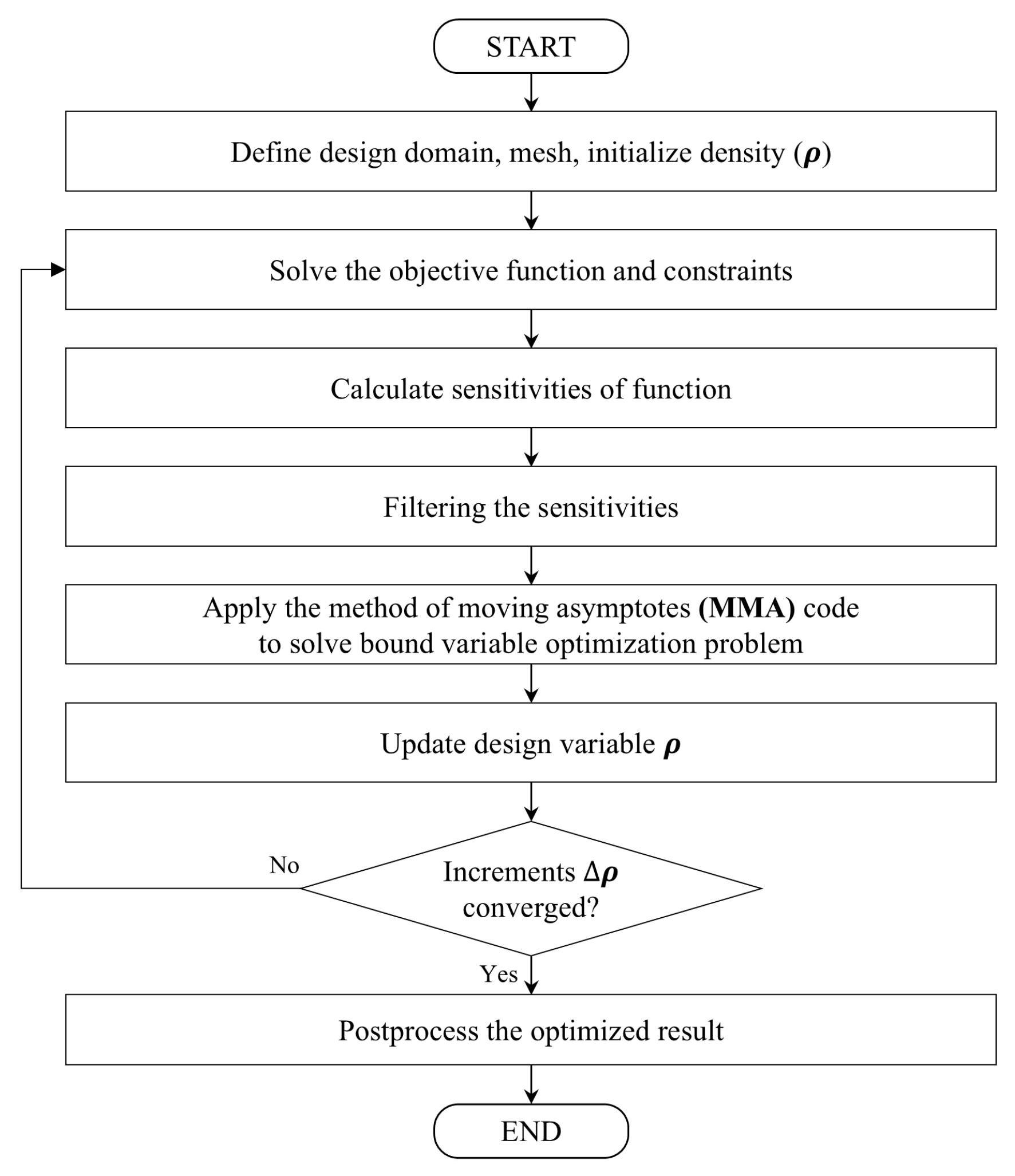
Figure 1 shows the overall topology-optimization process.
Figure 1 presents the flowchart of the topology-optimization process. The procedure begins by defining the design domain and initializing the design variables; density (
ρ) was set as the design variable. Four different formulations were employed to define the objective function and constraints: (1) compliance minimization, (2) compliance minimization with a natural-frequency constraint, (3) natural-frequency maximization, and (4) natural-frequency maximization with a compliance constraint. After evaluating the objective function and constraints, a sensitivity analysis is performed to calculate the gradient of the objective and constraint functions of the design variables. A sensitivity filtering technique is then applied to mitigate numerical instabilities, such as checkerboarding and mesh dependency, by averaging the sensitivity over neighboring elements. The method of moving asymptotes (MMA) is used as an optimization algorithm, which iteratively updates the design variables based on sensitivity information, while efficiently handling multiple constraints. This iterative process continues until the changes in the element density values between iterations become negligible, thereby indicating convergence. Finally, the optimized result underwent post-processing, including density thresholding, to extract a clear and manufacturable structural topology from the fixed-grid model.
2.1. Finite-Element Method Model Based on Fixed Grid
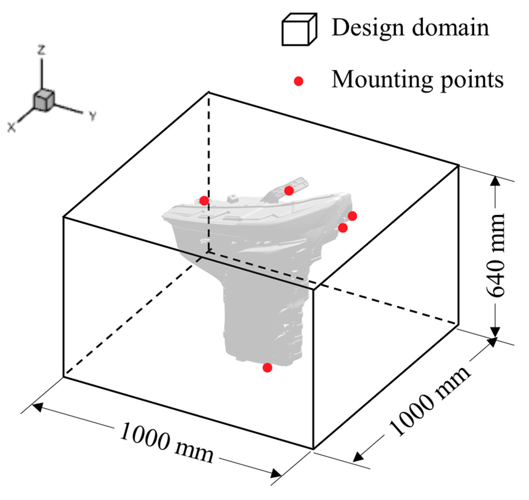
In this study, the geometric configuration and mounting positions of the finite-element model were defined based on the actual jig setup and expander size of the testing machine, as illustrated in
Figure 2. The expander measured 1000 × 1000 mm, which was applied as the base dimensions of the model, and the height was set to 640 mm to represent the location of the top mounting point where the lamp was secured.
The finite-element model was created using a fixed grid to address elasticity problems with high accuracy. The fixed-grid approach can adapt to changing design conditions through simple modifications by preserving the design space in fixed regions during the optimization process [
17,
23]. It also reduces the computational cost of optimization within the proposed design domain. In particular, optimal results can be obtained more rapidly than with conventional optimal design methods for large-scale problems and increase the likelihood of reaching the global optimal solution.
After creating the design domain as a basic hexahedron, the area occupied by the lamp was excluded from element generation because it was an infeasible region for optimization. The bolt-fastening region at the bottom, which connects the testing machine and jig, was retained in the design domain; all degrees of freedom of the nodes in this region were constrained.
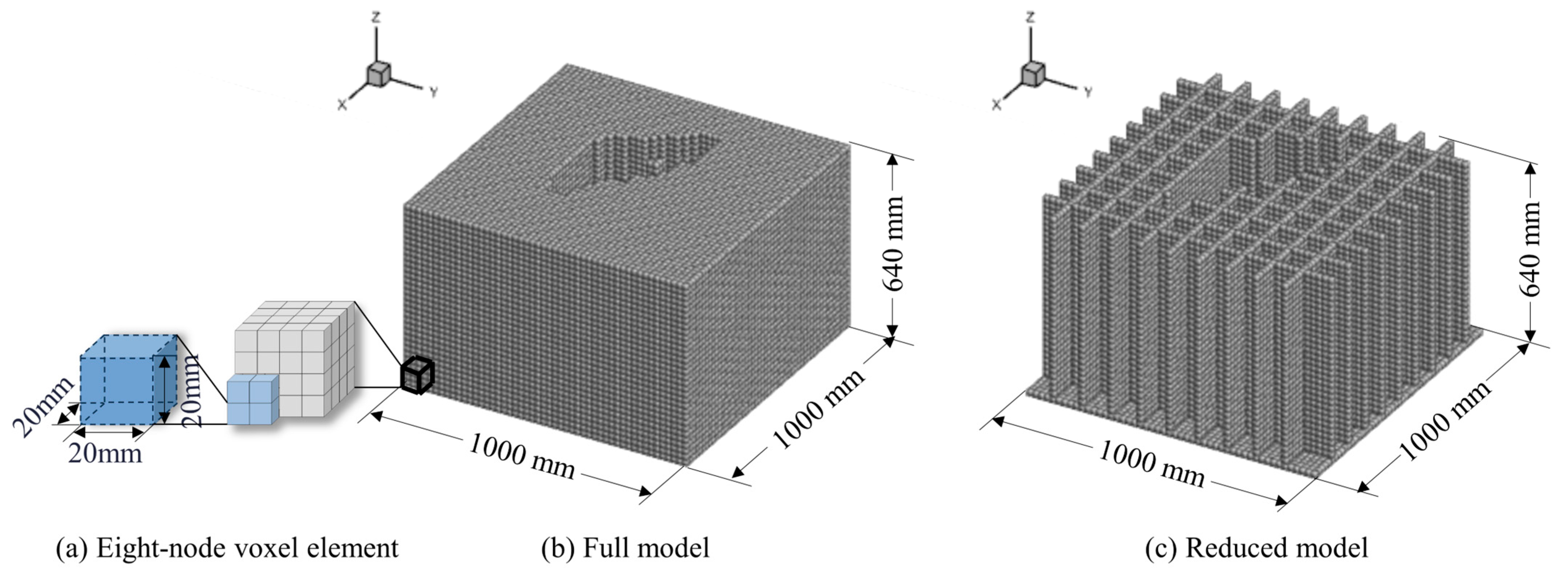
The fixed-grid-based design domain was discretized using eight-node cubic elements with dimensions of 20 × 20 × 20 mm (
Figure 3a). This element size was selected based on the typical rib thickness used in the vibration test jigs, which was 20 mm. The SOLID185 element provided by ANSYS 2024 R1 APDL (ANSYS, Inc., Canonsburg, PA, USA) was used in this study. SOLID185 has three degrees of freedom at each node along the x, y, and z axes, and is commonly used in three-dimensional (3D) vibration analysis. Two finite-element models were defined to analyze the changes in topology optimization depending on the design domain. First, the full model had no restrictions on the cubic design domain (
Figure 3b).
In this model, the entire feasible domain, excluding regions that interfere with the lamps, was designated as the designable region, thereby maximizing design freedom. The model did not include internal voids, which allowed the generation of highly complex geometries. However, an increase in the number of finite elements results in a higher computational cost. Second, the reduced model features ribs arranged in an 80 mm interval lattice structure (
Figure 3c). To reflect the typical thin aluminum rib structures used in practical jig manufacturing, the feasible domain was restricted to grid intersections in the XY plane, where ribs can be generated. Regions in which interference with the lamp occurred were excluded from the mesh. Owing to the presence of voids between lattice lines, this model significantly reduces the number of finite elements and computational time, although it offers relatively lower design freedom compared to the full model.
The elastic modulus of each element was assigned by converting the density of the element based on the solid isotropic material with penalization, as shown in Equation (1) [
24,
25].
where
is the
-th elastic modulus,
is the density value of the
-th element, and
is penalization factor. In topology optimization, each element’s density value is a relative measure. A penalization factor of 3 was applied for convergence [
24].
is the elastic modulus when the density value is 1; the material properties for aluminum die-casting (elastic modulus: 69.65 GPa; Poisson’s ratio: 0.33; and density: 2.75 g/cm
3), which is the main material of the jig, were used. Because the dimensions of the finite-element model were in millimeters, all material properties were converted to millimeter units.
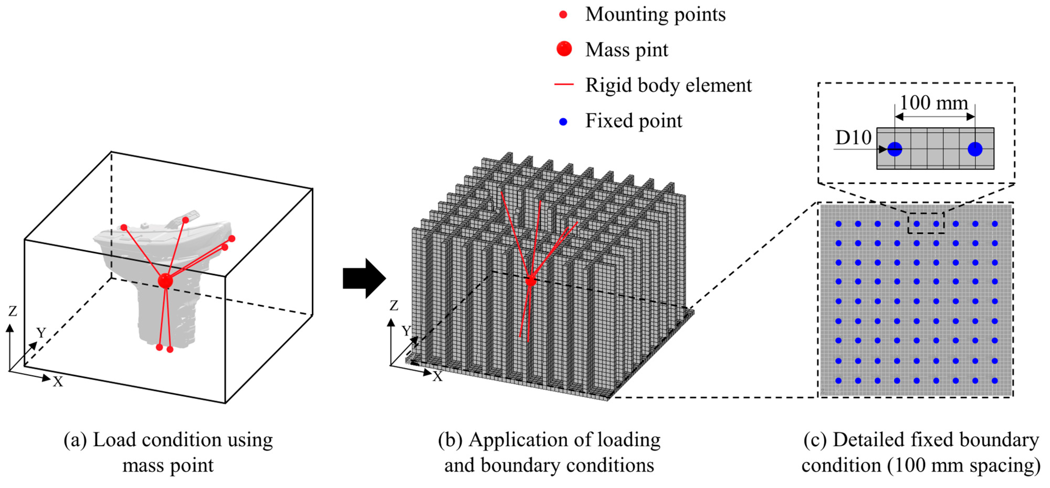
As illustrated in
Figure 4, six mounting points corresponding to the lamp’s attachment locations were connected to its center of gravity using rigid body elements, and a concentrated mass was applied at that central point to represent the lamp’s weight. Fixed boundary conditions were applied at the bottom of the design domain to reflect the bolt pattern of the expander, with a spacing of 100 mm. Specifically, all degrees of freedom were constrained for nodes located within cylindrical regions 10 mm in diameter and 20 mm in height at each bolt location.
2.2. Formalization of Topology Optimization
A vibration test jig is a key piece of equipment for accurately reproducing and demonstrating the vibration characteristics of a structure or component in a testing environment. Therefore, it must be designed to consider both stiffness and natural frequency. To derive a topology optimization that meets all the multiple performance requirements for the jig, four formalization methods commonly used in vibration-performance topology optimization were applied.
Thus, four topology-optimization formulas were formalized to perform optimization considering the natural frequency. All formulas include density-value constraints and sensitivity equations and aim to reduce the weight of the vibration test jig while improving its natural frequency.
2.2.1. Formulation 1: Natural-Frequency Maximization
The first topology-optimization formula, Equation (2), uses compliance minimization as its objective function, and is commonly used in topology optimization. Here,
is the design variable that represents the density of the element,
is the displacement vector,
is the stiffness matrix of the element,
is the total number of elements,
is the volume of the element,
is the volume of the entire design domain, and
denotes the allowable constraint tolerance.
2.2.2. Formulation 2: Natural-Frequency Maximization with Compliance Constraint
The second topology-optimization formula, Equation (3), uses compliance minimization as its objective function and includes the natural frequency as a constraint. It aims to satisfy a target natural-frequency range while considering stiffness. Here,
is the target value of the primary natural frequency,
is the natural frequency of the finite-element model updated in each iteration,
is the mass matrix, and
and
represent the tolerances of allowable constraints.
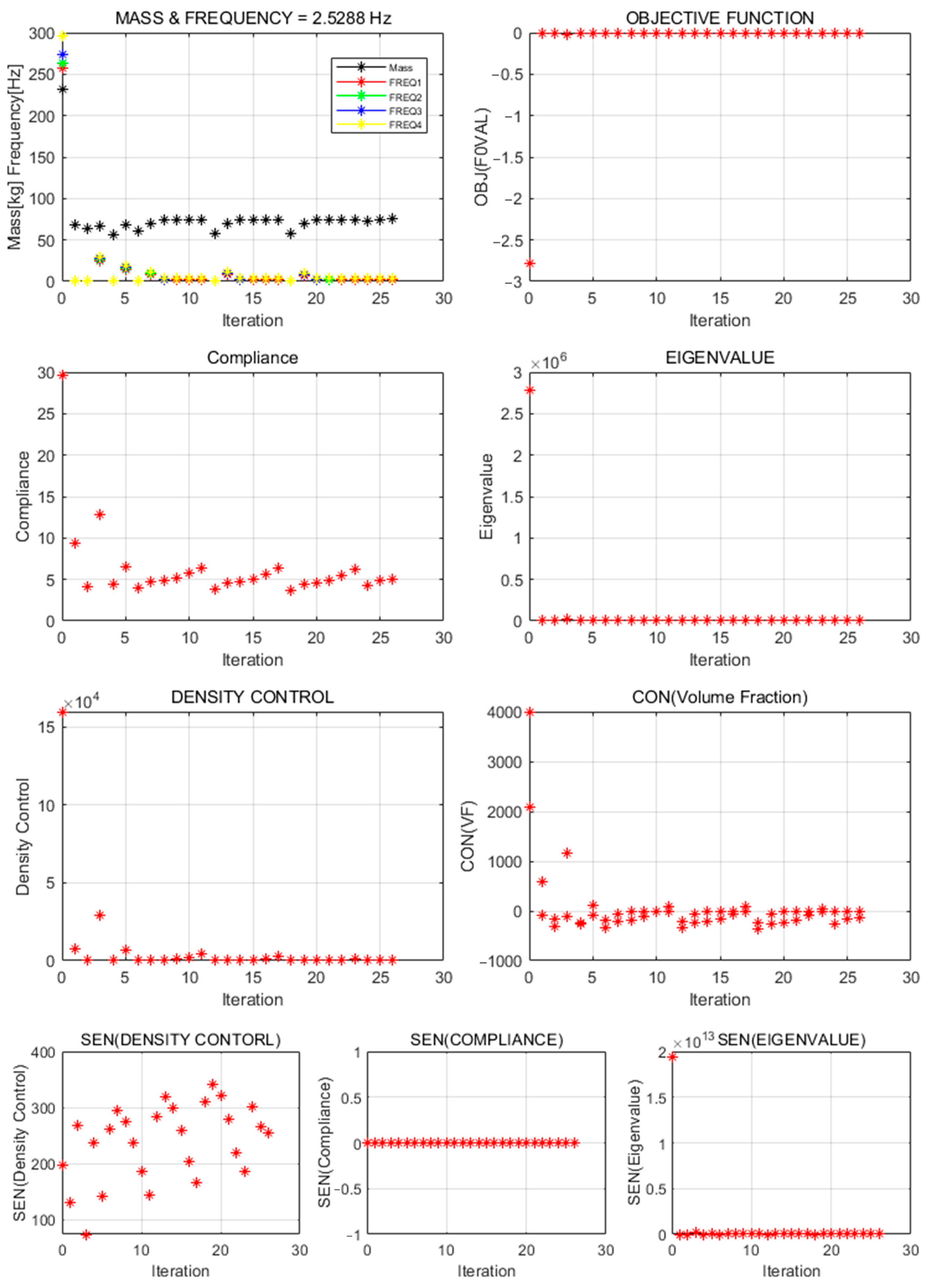
2.2.3. Formulation 3: Compliance Minimization
The third topology-optimization formula, Equation (4), uses eigenvalue maximization as its objective function [
21]. Optimization that considers only the natural frequency may produce unrealistic geometries or loss of stiffness, as confirmed by the final results. Therefore, a compliance constraint for all fixed elements in the fixed grid is required to ensure kinetic-energy uniformity.
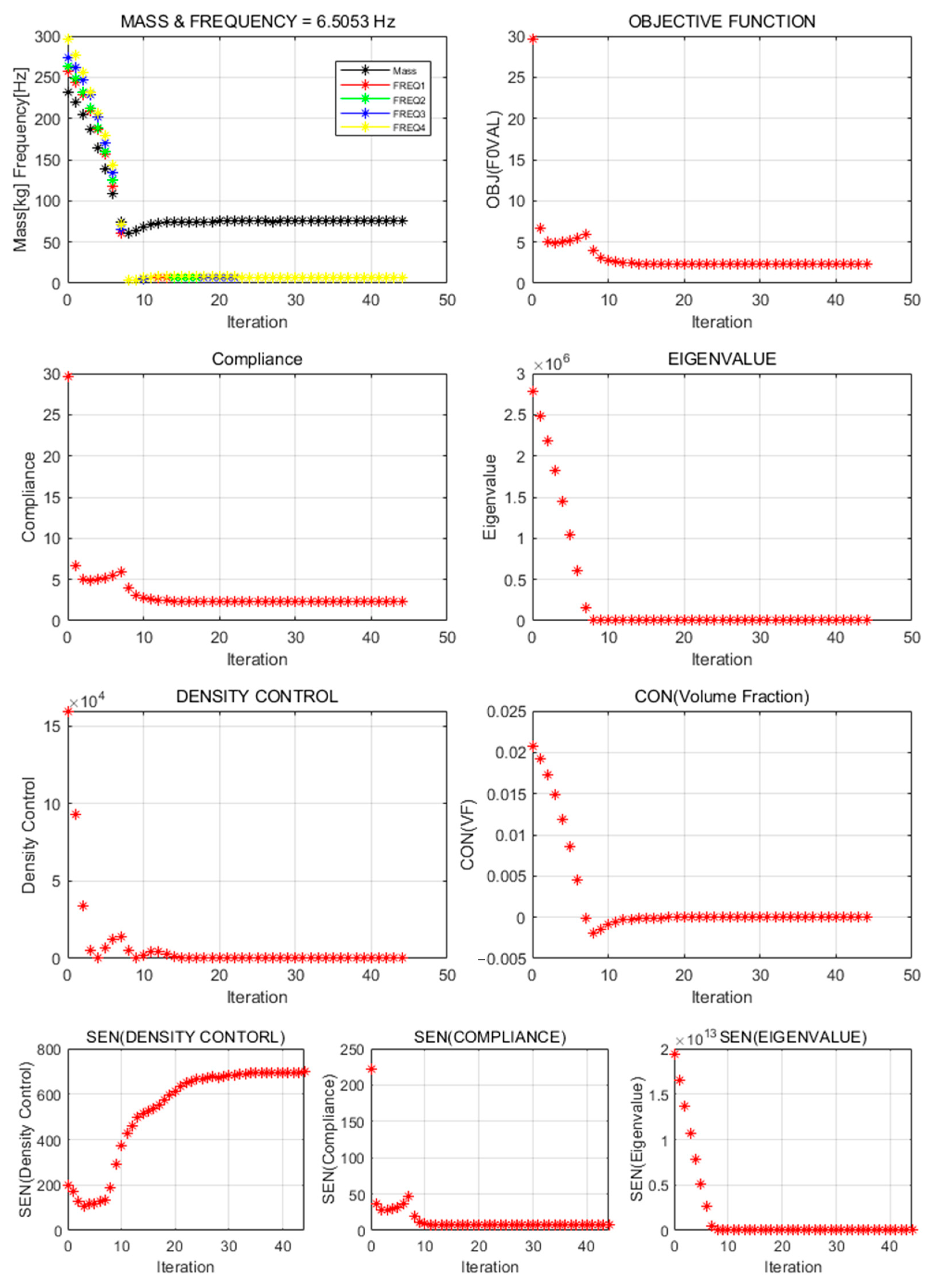
2.2.4. Formulation 4: Compliance Minimization with Natural-Frequency Constraint
The fourth topology-optimization formula, Equation (5), uses eigenvalue maximization as its objective function and includes compliance as a constraint; 20% of the compliance value derived from the first iteration was selected.
Because the finite-element models in this study contain more than 50,000 eight-node hexahedral elements, the range and magnitude of values may vary depending on the objective functions and constraints. These differences can make it difficult for the optimization algorithm to handle all variables and constraints appropriately. This issue was addressed by adjusting scale parameters.
In topology optimization, various numerical parameters and scaling coefficients are applied to control the relative influence of objective functions and constraints, as well as to define key design requirements, such as volume fraction, target compliance, and frequency thresholds. These parameters are essential for balancing multi-objective performance, improving numerical conditioning, and enhancing convergence stability during the optimization process. Proper scaling also enables a more equitable treatment of multiple objectives and facilitates a clearer interpretation of the results. Therefore, in this study, topology optimization was performed by applying both scaling coefficients and key parameter values across different formulations and domain configurations, as summarized in
Table 1. Note that “—” means it is not included in the formulation.
All scale and parameter values in
Table 1 started with a default value of 1. Values matching the magnitudes of the objective functions and constraints were applied based on the results of the first iteration. The frequency set for stiffness maximization with a natural-frequency constraint was the lower limit (
). The compliance limit for natural-frequency maximization with a stiffness constraint was set to the upper limit, and 20% of the value derived from the initial model was applied.
2.3. Topology Optimization
In this study, the topology-optimization design domain was defined by excluding the region occupied by the lamp from the cubic finite-element model. The two models were created using identical specifications. The total design variables were the density values of each element: 75,560 elements for the full model and 26,282 for the reduced model. To reduce numerical instabilities arising from the element size, sensitivity filtering of the surrounding elements was applied (Equation (6)) to prevent checkerboarding.
where
is the filter size (the application range of sensitivity filtering), and
is the Euclidean distance between two points [
26,
27]. In this study,
was set to 40 for all topology-optimization runs. The parameters and variables with identical values are listed in
Table 2. Note that “—” means it is not included in the formulation.
TECPLOT 360 EX 2022 R2, a data visualization and analysis software, was used to examine the topology-optimization results. Penalization was confirmed by removing elements with density values of 0.5 to 0.7, which are difficult to manufacture. Thresholding was then performed on the final jig topology to verify the model performance via finite-element analysis. Thresholding, a preprocessing technique used in image processing and computer vision, selects or separates areas of interest (pixels or regions). This step, which is essential for fixed-grid topology optimization, involves (1) selecting an appropriate density threshold in TECPLOT, (2) comparing all element densities to that threshold, and (3) excluding elements below the threshold from the final finite-element model. This preprocessing yields feasible design representations from the fixed-grid models.
Topology optimization was executed using in-house MATLAB R2023a code. The resulting input data were then imported into Mechanical APDL Product Launcher 2022 R1 for finite-element analysis. The average optimization run time was 4 h on a HP OMEN 40L workstation Intel Core™ i9-12900K (Intel Corporation, Santa Clara, CA, USA). The MMA [
28] was used as the optimization algorithm.
4. Discussion
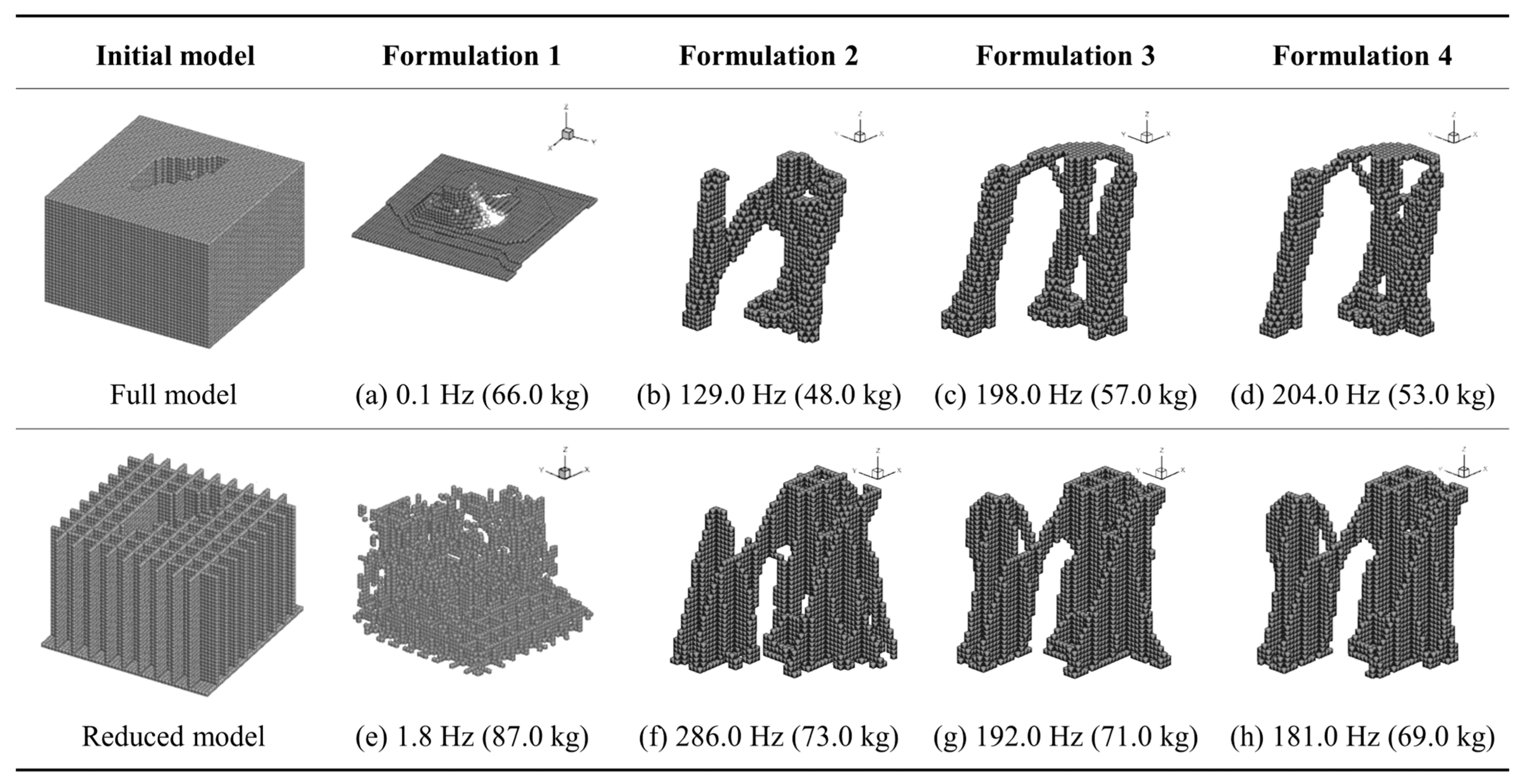
In this study, topology-optimization strategies were proposed to achieve both natural-frequency maximization and weight reduction for the vibration test jig. Full-domain and reduced-domain models were applied across four formalization methods, and the results were compared and analyzed. Major performance indicators—structural geometry, natural frequency, and weight—varied, clearly depending on the configuration of design objective functions and constraints.
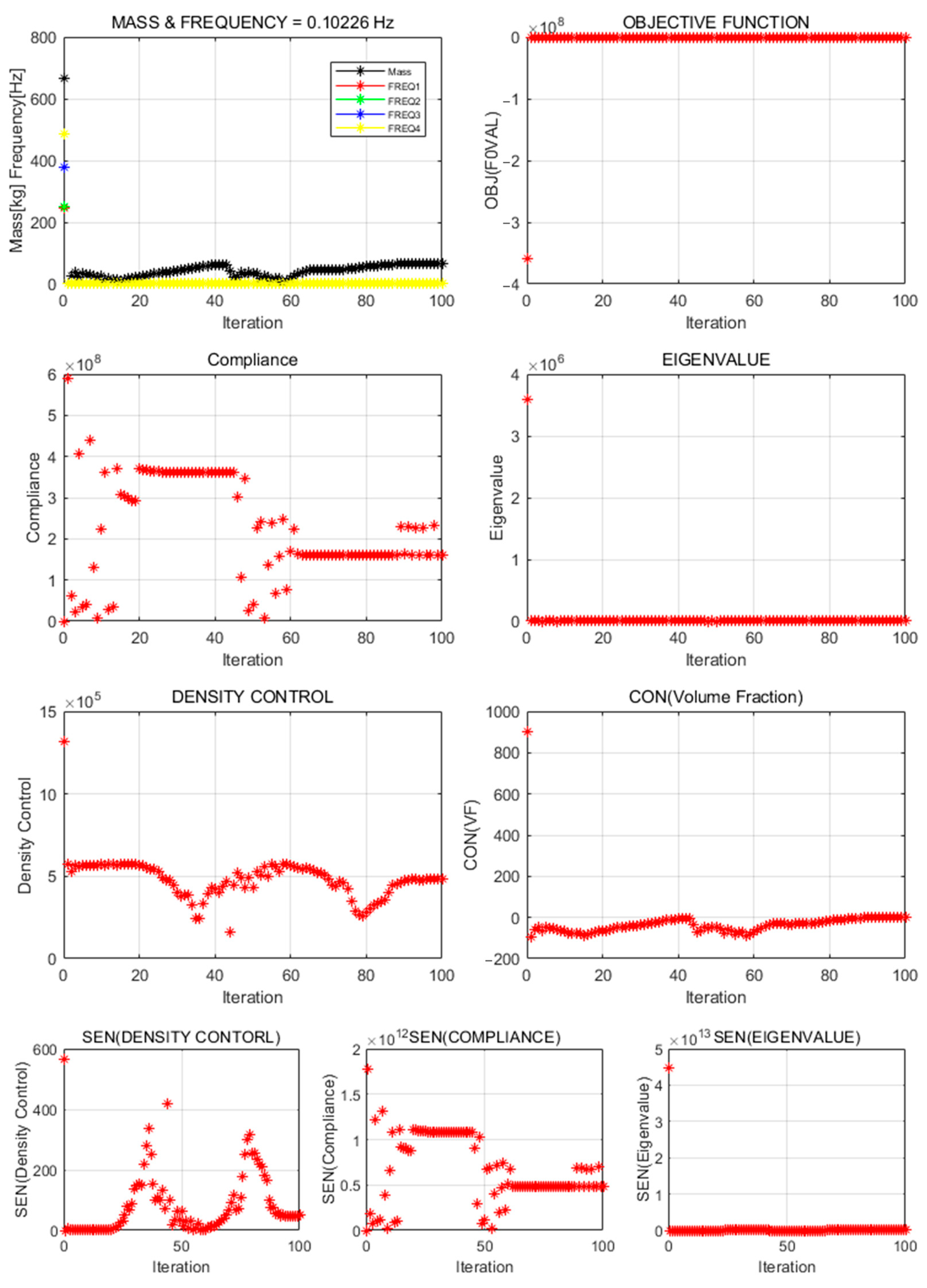
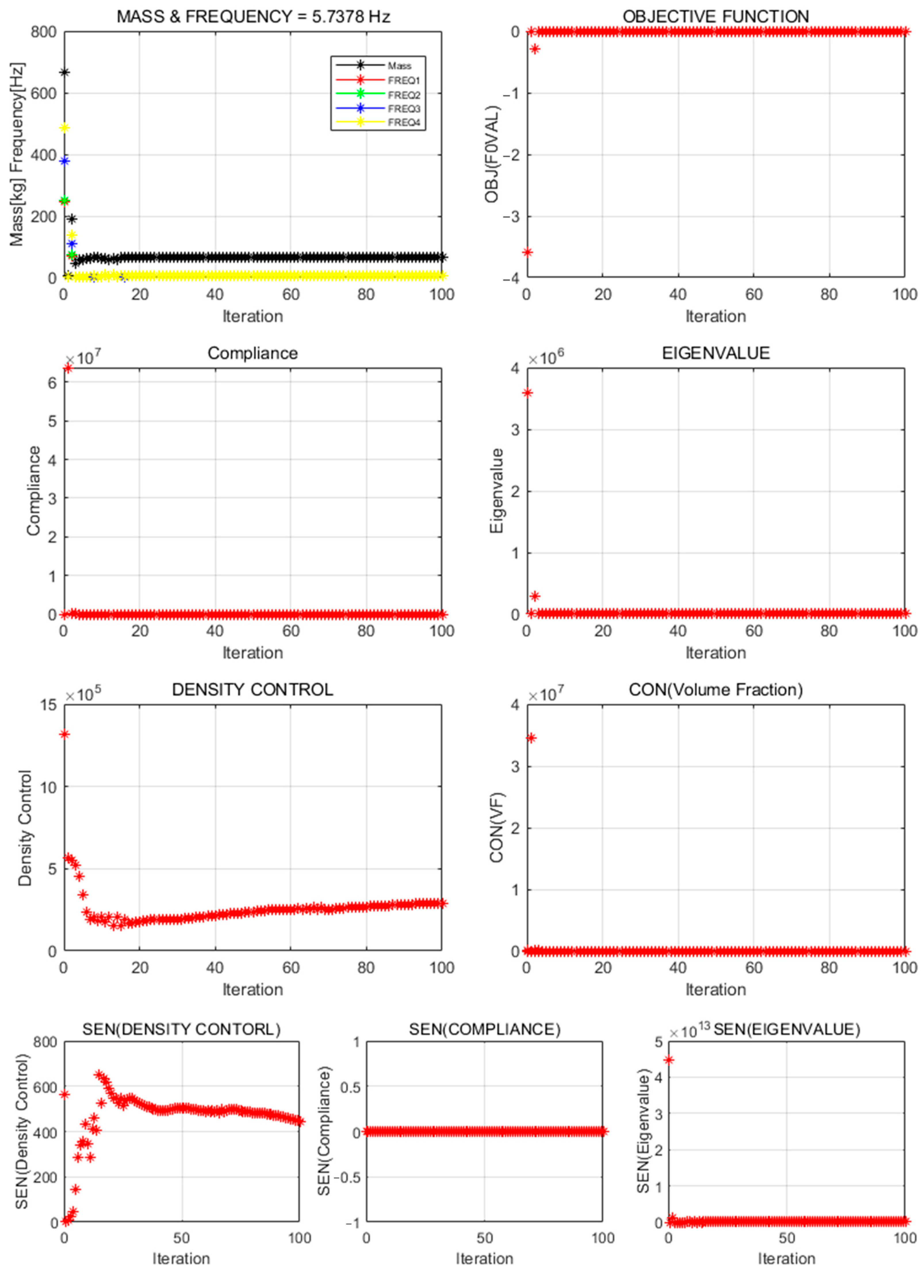
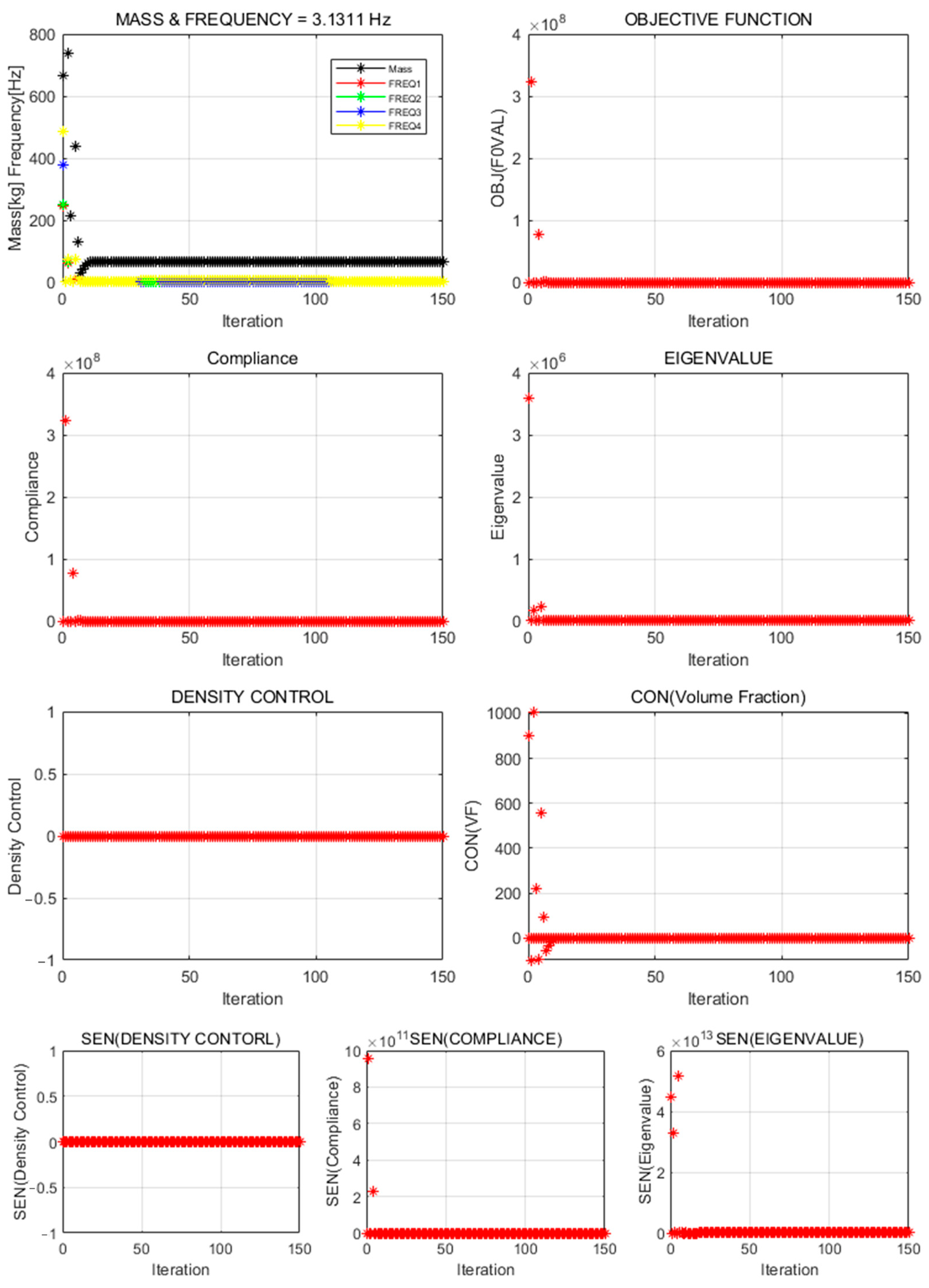
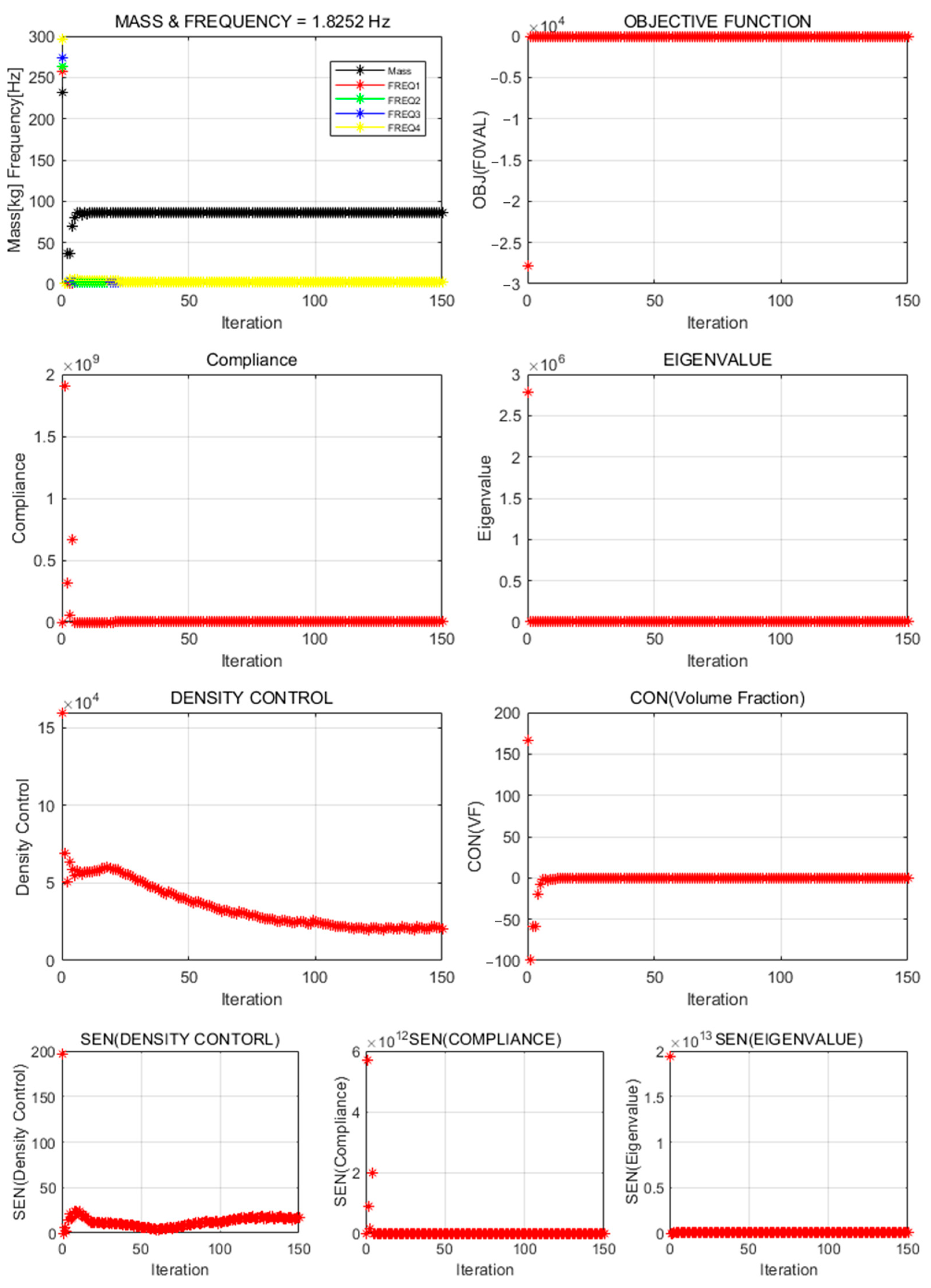
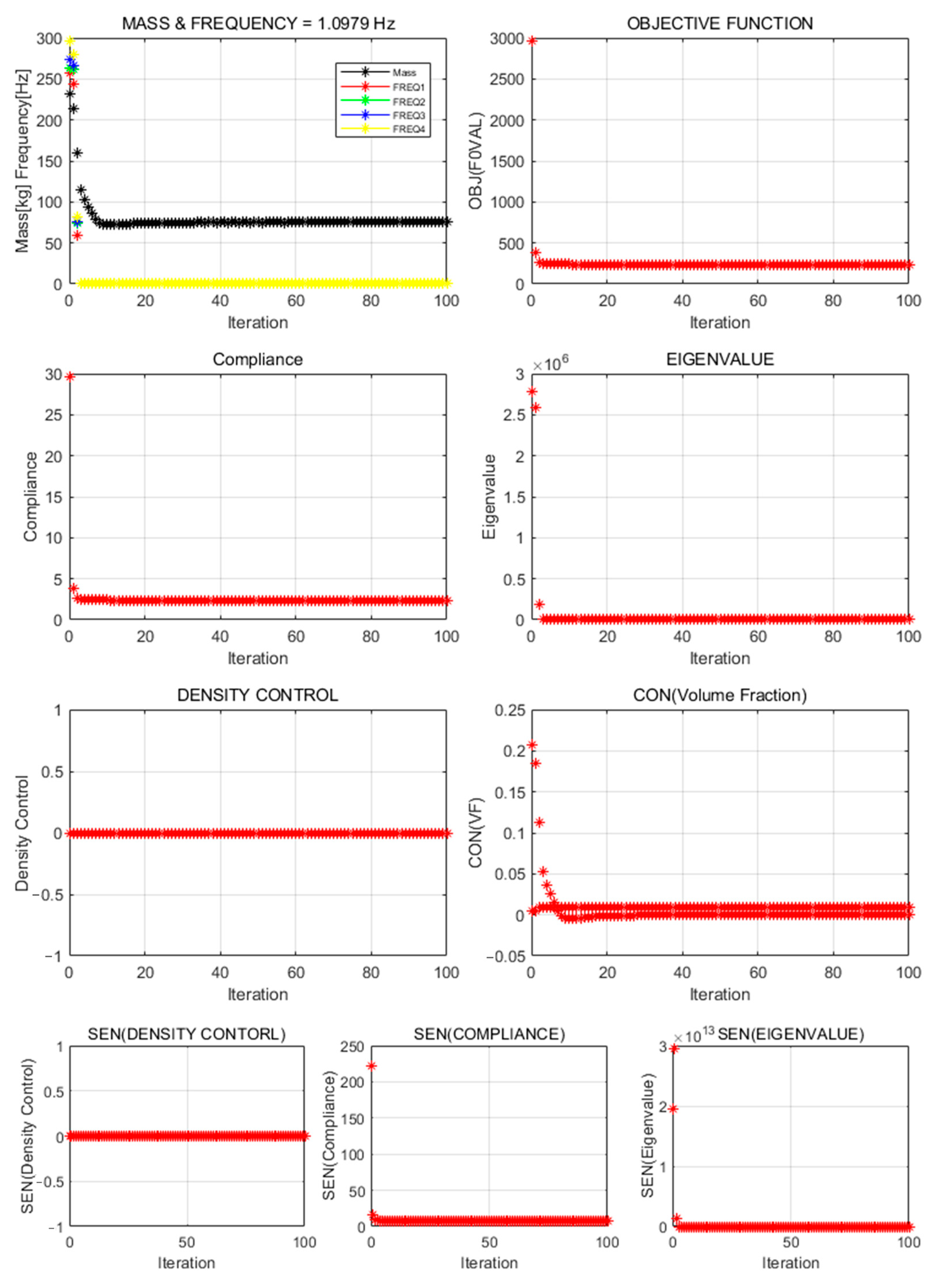
When only the natural frequency was set as the objective, the structural geometry diverged, or no viable structure was formed in either model. This failure likely resulted from insufficient penalization or low material density. In particular, ALDC materials showed reduced convergence in the natural-frequency-based formalization owing to their lower stiffness compared to high-strength metals such as iron and titanium. In contrast, formalizations that included compliance or treated natural frequency as a constraint exhibited stable convergence and produced practical, significant structural geometries. This finding indicates that stiffness-based constraints should accompany natural-frequency objectives, which is consistent with existing multi-objective optimization studies [
31,
32,
33].
4.1. Structural Geometry Characteristics According to Model Scope
The derived geometry differed considerably, depending on the design-domain configuration. In the full-domain method, a thick, column-shaped structure is formed along the load-transmission path between the top mounting points and the bottom support, with the column’s cross-sectional area gradually increasing toward the base, reflecting a stable load distribution. In the reduced model, a topology with triangular ribs radiating around mounting points was observed. Notably, wall-shaped structures appeared at higher mounting positions. These rib and wall structures address the local dynamic behavior within a limited domain. Both models produced continuous connections between the top mounting points, thereby increasing the stiffness for local (bending) modes, which resulted in improved global modal frequencies and enhanced dynamic stability. Thus, domain definition affects structural geometry, vibration characteristics, and design strategy, indicating that initial topology-optimization inputs significantly influence result interpretation. This viewpoint is further supported by recent studies, such as those by Rong et al. [
34], who proposed an adaptive design-domain strategy for structural topology optimization. Their findings revealed that modifying the design domain in response to optimization feedback significantly improved both structural performance and computational efficiency. Designers should, therefore, define domain scope in line with objectives and treat domain configuration as part of the interpretation strategy.
4.2. Securing Natural Frequency and Interaction Between Design Freedoms
The natural-frequency and weight-performance characteristics differed clearly according to the model configuration. The reduced model consistently achieved higher natural frequencies than the full model; notably, Formalization 2 (natural-frequency maximization with compliance constraint) delivered the highest result—286.0 Hz—across all cases. This performance suggests that fine, grid-based design freedom effectively enhances the natural frequency, as concentrated material distribution efficiently controls specific vibration modes within a limited domain. Meanwhile, the reduced model exhibited a higher weight than the full model in most formalizations because the material was distributed more uniformly and finely. Thus, increasing the design freedom to enhance the natural frequency may result in a weight penalty. Designers must therefore establish clear “vibration-performance-oriented” or “weight-reduction-oriented” criteria in advance and select formalization and domain configurations accordingly. This approach can guide future multi-objective optimal-structure designs.
4.3. Performance Comparison and Trade-Off Analysis by Formalization
Formalization methods yielded distinct trade-offs between natural frequency and weight. The natural-frequency maximization with compliance constraint formalization achieved the highest natural frequency (286.0 Hz) in the reduced model; however, its weight (73.0 kg) exceeded that of the full model (48.0 kg), likely owing to the concentrated material distribution. Meanwhile, the density-control-term formalization secured a high natural frequency while maintaining a relatively low weight (approximately 70 kg) and exhibited excellent convergence stability. A similar trend was observed in a study by Yin et al. [
35], who proposed a multi-objective topology optimization approach for thin-plate structures. They highlighted the effectiveness of balancing stiffness, vibration performance, and lightweight design through appropriate multi-objective formulations. These results demonstrate the potential of multi-objective formalizations that limit the weight increase while improving the natural frequency.
4.4. Limitations and Future Research
This study has the following limitations. First, a jig combined with an actual lamp was installed in the testing machine; therefore, a lighter structure than the current geometry is required to improve installation convenience and operational efficiency. Future work will refine the weight reduction by adding geometric and dimensional optimization steps. Second, fixed boundary conditions were uniformly applied to the entire jig domain; actual bolt-fastening conditions between the machine and jig were not reflected. Future modeling will incorporate the actual fastening positions and configurations to enable a more realistic dynamic analysis. Third, this study targeted the natural-frequency improvement under a single test condition (e.g., vibration load in one direction), whereas real test environments involve various dynamic loads (e.g., multiaxial vibration, impacts, and complex load conditions). Consequently, ensuring design versatility across multiple scenarios remains a challenge. Future research will expand to multi-objective topology optimization across multiple frequency bands and multiaxial load conditions. Lastly, this study used a uniformly fixed boundary condition, which may limit the ability of the vibration test jig to reflect actual dynamic behavior. However, this study observed that this assumption did not significantly affect the overall optimization results within the scope of this study. Future research will consider the boundary condition in which the vibration test jig experiences realistic conditions (e.g., bolt preload or contact-based). These enhancements are expected to yield more practical and broadly applicable jig designs, ultimately improving the reliability and efficiency of automotive part testing equipment.


