1. Introduction
Variable structure systems (VSS) with sliding modes (SM) are a striking example of the effectiveness of the use of new mathematical methods in technical automation systems.
In these systems, the theory of which is exhaustively described in the books of Emelyanov S.V. and Utkin V.I. [
1,
2,
3,
4], transient processes are formed by switching the feedback sign in the vicinity of the sliding space (or trajectory).
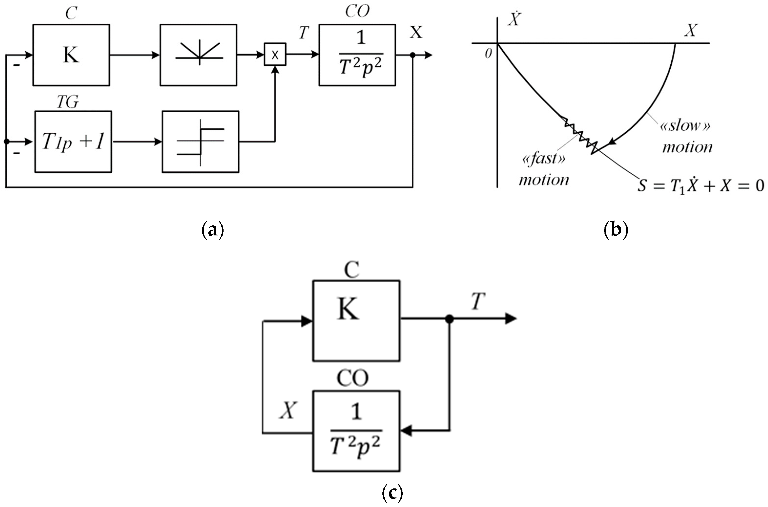
The essence of this control is that in a certain region of the phase space around the switching surface, conditions for counter movements are created. The phase trajectory is “decomposed” into two movements: fast and slow. These movements have the necessary rigidity to external disturbances and changes in system parameters. When the sign of the feedback changes, the control forms a switching line (surface), on which the phase trajectory of the automatic control system (ACS) remains until the end of the transient process. In this case, the switching surface is a “slow” movement and movements around the surface are “fast”.
Most often, the creation of discontinuous controls in real automatic control systems creates undesirable oscillatory processes. Therefore, when creating sliding processes, it is important to take into account the specific parameters of “fast” movements, i.e., their frequency and amplitude. An ideal glide is considered to be one in which the frequency of “fast” movements is very high and the amplitude is very small. But in reality, it is very difficult to obtain such processes. They are influenced by small inertia and delays in the ACS, nonlinearities, etc. It is very difficult to take their influence into account in differential equations. In traditional ACS, their influence is effectively taken into account by the frequency characteristics of the ACS units. Therefore, the task of assessing sliding processes using frequency methods is very relevant.
Conditions for Ideal Sliding of Second-Order VSS
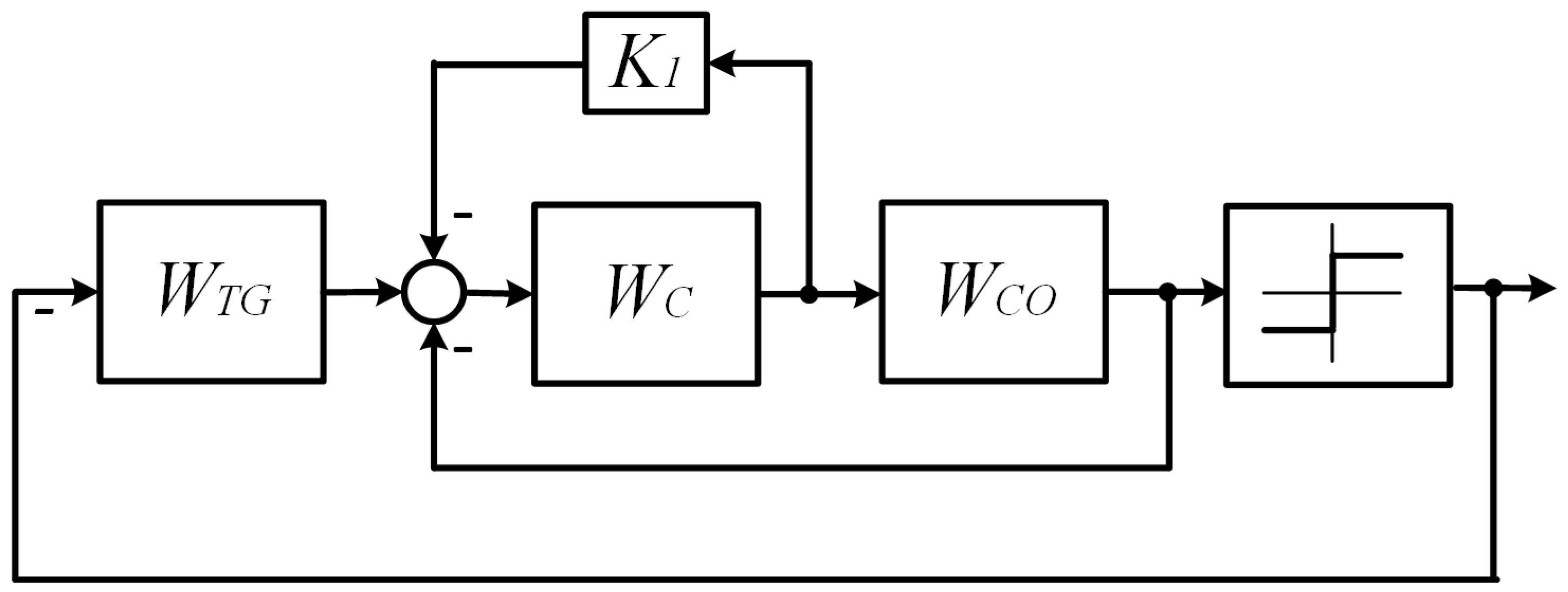
Figure 1 shows an ACS of the second order, in which the control object (CO) is a double integrator, as the link most prone to instability among the elementary dynamic links; the controller (C) is an amplifier with coefficient K; and the switching trajectory shaper (TG) is a forcing link with time constant
.
Initial System of Differential Equations VSS:
In the works of Emelyanov and Utkin [
1,
2,
3,
4], a method of equivalent control was developed and conditions for the existence of sliding processes were obtained for systems with control objects described by differential equations of order n and sliding trajectory equations of order (n
−1). In work [
3], ideal SM conditions for electric drives were obtained, which are close to the systems presented in
Figure 1, using the equivalent control method for systems described by Equation (1).
The equivalent control method is close to the second Lyapunov method and evaluates the existence of a phase space in which, due to ACS Equation (1), the condition is satisfied in the vicinity of S = 0.
For systems described by Equation (1), these conditions are reduced to the following inequality:
, called the boundary time constant of the sliding trajectory, determines the boundary speed of sliding processes. The condition connects the time constant T1 of the sliding trajectory, the parameters of the control object (), and the parameters of the controller (K). The order of the control object and the order of the switching trajectory correspond to the conditions derived by S.V. Emelyanov and V.P. Utkin; therefore, the fulfillment of the conditions of slow movement simultaneously determines the absence of “fast” movements around the sliding trajectory with a finite frequency and amplitude. With ideal sliding, their frequency tends to ∞ and their amplitude tends to 0.
This principle of forming transient processes in automatic control systems, which requires high speed, seems very promising for electromechanical systems, in which fast and slow variables are always present. Fast movements are the armature current and the voltage at the motor armature; slow movements are the speed and angular movements of the output shaft.
2. Problem Statement: State of the Issue
However, studies of such systems very quickly confirmed that special, more accurate criteria for the existence of sliding processes for real automatic control systems are required. Moreover, some factors that were little taken into account in linear systems, for example, small delays of dynamic links, static external disturbances, limitations of mechanical moments, etc. in sliding mode systems can lead to qualitative changes in transient processes. Taking these features into account significantly complicated the criteria and conditions obtained for the main slow movement.
The work [
5] shows how sliding processes are influenced by discrete elements, but it is also very important to determine how small inertia of the control object affects them. To solve this problem, the method of analyzing the frequency characteristics of control systems with a variable structure (ACS with a variable structure) is very effective.
In recent years, many works have been published on sliding processes in automatic control systems [
6,
7,
8,
9,
10,
11,
12,
13,
14]. These works use methods similar to the equivalent control method [
5,
6,
7] or the second Lyapunov method [
8,
9]. The results of these calculations are most often quite difficult to apply in real control systems, particularly in electromechanical control systems.
According to the authors of this article, the widespread use of VSS in real automatic control systems will be facilitated by sliding criteria that work “universally” in technical systems containing known features—nonlinearity, delays, and high-order links. Also, how stability criteria “work” in linear and nonlinear automatic control systems has been investigated by Nyquist and V.M. Popov [
1,
2,
3,
4,
5], whose studies were very close to each other in final formulations and mathematical content.
In a previously published work [
5], “engineering” criteria for sliding according to the frequency characteristics of an automatic control system with a variable structure were formulated. Further, with the help of simulation, it was shown how sliding is carried out in systems with discretization of various regulator channels. This article presents the results of simulation ACS, in which, in addition to double integrators that describe the main inertia of electromechanical ACS, links with lower inertia are introduced. Most electromechanical automatic control systems can be reduced to such structures. Attempts to construct sliding processes in such systems in accordance with the above methods (using differential equations with the order of the switching trajectory one below the order of the equation) lead to a significant complication of the ACS. It becomes necessary to build observers and supplement the ACS with models for indirectly measuring the coordinates that are necessary to form the switching trajectory. Moreover, this coordinate cannot be measured in reality. The frequency method proposed in [
5] can largely solve these problems. Frequency criteria make it possible to solve the problems of synthesizing “real slip”, i.e., having finite parameters of “fast” movements—their amplitude and frequency.
Let us return to the sliding condition obtained for second-order control systems. Let us take into account that the time constant is a parameter determined by the circuit formed by the control object CO and the controller C.
Condition (2) can be formulated as follows: the time constant of the sliding trajectory must be greater than the time constant of the circuit formed by the control object link and the regulator link.
2.1. On the Connection between Electromechanical Automatic Control Systems and Second-Order Automatic Control Systems
Most real electromechanical automatic control systems can be represented with sufficient accuracy by a combination of a double integrator and a high-order link or nonlinear structures. This approach is widespread both in works on sliding processes and in works on the stability of nonlinear automatic control systems.
In almost all electromechanical systems, connections in mechanical links are described by integrators with time constants of 0.1–10 s, electrical connections are described by inertia with time constants of 0.001–0.1 s, and the non-rigidity of the gearbox is described by oscillatory structures with time constants of 0.1–1 s. Thus, the presence of a double integrator with large time constants and other features for the analysis of sliding processes should be considered acceptable. Verification of the proposed criteria by mathematical simulation in this example can be considered sufficient. In all of these works, the provisions are also confirmed by theoretical calculations or simulation.
The condition for electromechanical systems can be interpreted by the logarithmic frequency characteristics (LFC) of the ACS elements presented in
Figure 1.
Figure 2 shows the LFC structure and transient diagrams for various options for fulfilling condition (2).
Figure 2a–c show the frequency characteristics of the link that forms the sliding trajectory
(forcing link) and the circuit formed by the amplifier link
C and the control object
CO—A double integrator (
Figure 1c).
The transfer function of this circuit is as follows:
The process in
Figure 2a corresponds to ideal sliding. The sliding condition (2) is satisfied. In this case, condition (2) is equivalent to two conditions connecting the frequency characteristics of ACS blocks:
- -
The condition for ideal sliding of the VSS is satisfied if two links—the slip former and the circuit, including the regulator and the control object—form a series connection, the equivalent phase characteristic of which does not pass the value (−90°) and (−90°) is achieved at ω →∞.
The fulfillment of this condition is very clearly verified by the amplitude-phase characteristics of the control system, including the logarithmic characteristics (LFC in
Figure 2).
The same condition can be formulated as follows:
- -
Sliding processes will exist if the real part of the complex frequency transfers function of the serial connection of the circuit path shaper link formed by the control object and the controller is positive over the entire frequency range:
This condition, in turn, is the condition for the absolute stability [
2] of an equivalent circuit containing the same links in a slightly different configuration, shown in
Figure 3.
VSS replacement scheme:
Specifically, the stability of this system according to V.M. Popov [
15,
16] coincides with the existence of ideal sliding processes in the original scheme, and instability with violation of these conditions is shown in
Figure 2b.
Figure 2b shows the characteristics and processes when conditions (2) are not met.
If condition (2) is not met, then the process is self-oscillatory, as in
Figure 2b. In this case, at a frequency less than the cutoff frequency of the sliding trajectory shaper,
, the phase shift of the series connection of the TG links and the circuit reaches values less than (−90°). There are no stable, slow slips in the VSS. The equivalent circuit is unstable in this case since condition (4) is violated.
Let us propose a hypothesis that the stability condition (5), corresponding to the ideal sliding condition (2), will be preserved for any systems whose frequency characteristics satisfy condition (5). Then, applying the criterion of V.M. Popov, one can obtain a very convenient interpretation of various variants of sliding modes, which is extremely important for the practical application of SM in VSS.
Condition for the existence of sliding processes in systems of arbitrary order.
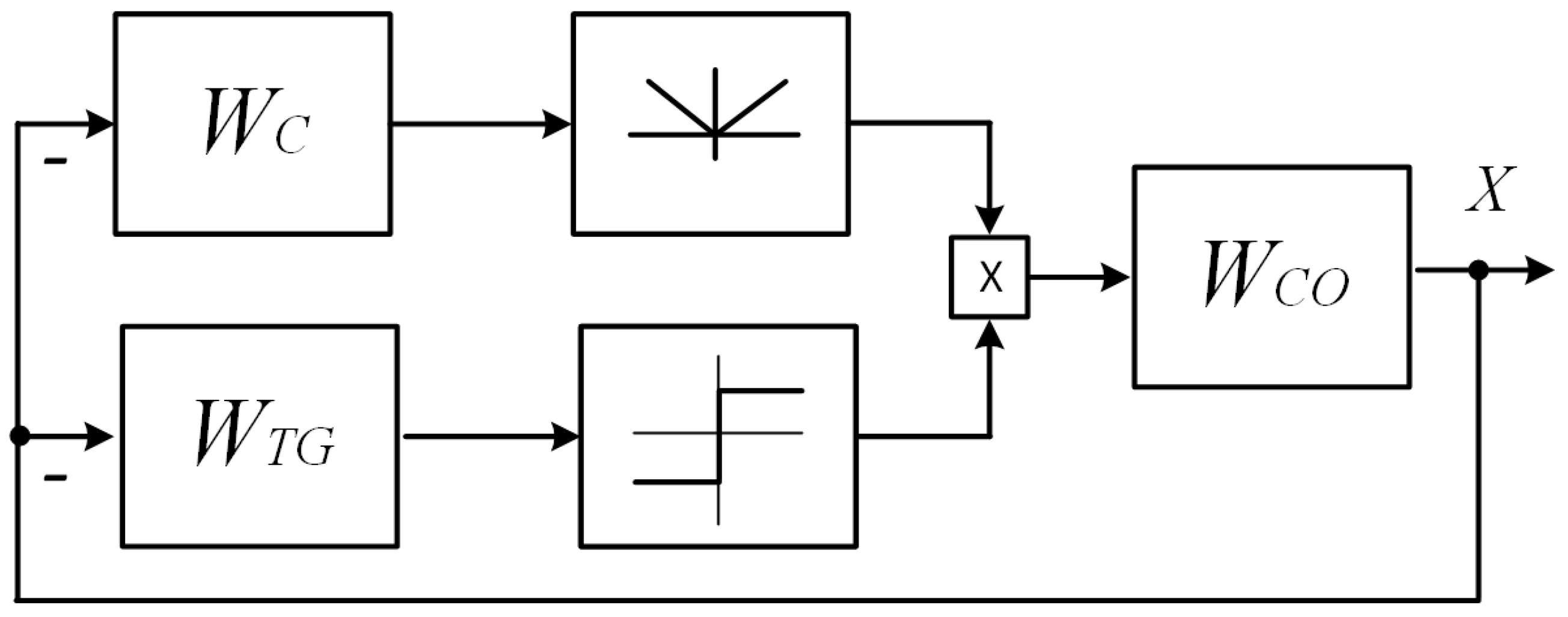
In a control system with a variable structure, with a control object of a general type (
Figure 4), a sliding mode will exist if the condition of absolute stability is satisfied for its equivalent circuit (
Figure 5):
or
This sliding condition can be applied to automatic control systems with nonlinear links in the control object and high-order links, and be the basis of engineering criteria for sliding processes.
The stability criterion in the equivalent circuit (4) can be used to assess the presence of slippage in the original system (1) when analyzing transient processes in a system with almost any nonlinear object, i.e., any object to which the theory of absolute stability is applicable, which excludes a detailed analysis of each specific case, as is performed in the theory of sliding processes in VSS [
1,
2,
3].
Particular attention should be paid to the fact that the proposed criterion (4) is very close to the stability criteria of linear and nonlinear automatic control systems that are familiar to engineers—the Nyquist and V.M. Popov criteria.
2.2. Real Sliding
Let us consider the case of an automatic control system with additional inertial links.
If condition (2) is satisfied for the values of the time constants of the control object, but the VSS contains delay or hysteresis links that change the transfer functions of the control object (CO) and their frequency characteristics in the high-frequency region, the real sliding mode begins in the VSS—fast movements have a finite frequency and amplitude. This is shown in
Figure 2c and is clearly shown by the frequency conditions (2)–(5). In the high-frequency zone, there is a region of space in which sliding movements do not exist—that is, fast movements have finite parameters.
Due to the characteristics of the object, the phase shift reaches a critical value (−90°) at a finite frequency and amplitude, which determines the parameters of fast movements (
Figure 2c).
This condition is very important for real automatic control systems. In the substitution diagram, this circumstance will be clearly “embodied”.
The frequency at which equality is satisfied is the frequency of self-oscillations in the equivalent circuit and the frequency of rapid movements in the existing sliding process. In this case, self-oscillations with a finite frequency and amplitude will exist in the equivalent circuit.
That is, the proposed frequency criteria for the existence of slip in an automatic control system of arbitrary order in terms of the stability of equivalent circuits make it possible to determine the parameters of real slip, i.e., their amplitude and frequency, which is very important for real electric drives. In this way, a frequency condition is obtained that is convenient for engineering calculations and does not connect the order of the control object and the order of the sliding trajectory—that is, the main problems have been overcome. We need to check this on models.
3. Theoretical «Origin» of the Problems
Variable structure systems are systems in which the control experiences discontinuities at the switching surface. The conditions for hyperstability of a nonlinear automatic control system imply the existence of a positive Lyapunov function [
5,
6], including an equilibrium state that has a negative sign derivative with respect to time due to the equation of the system. For a sliding process, the domain of existence of this function may exclude part of the space. For ideal sliding, only the switching surface itself can be excluded; for real, the part of the space around this surface can be excluded (
Figure 1b).
The area of this space will determine the conditions of oscillation of fast movements—their frequency and amplitude. Moreover, the frequency method will determine them very clearly and accurately: the frequency of violation of the sliding conditions will determine these parameters, first the frequency and then the amplitude of oscillations of the output coordinate in the equivalent circuit.
These real parameters are very important for real, automatic control systems. Therefore, let us check these provisions on the model. Frequency conditions show very well how high-order links influence the conditions for the existence of SM and the parameters of fast movements.
The frequency condition simultaneously analyzes processes both in the low-frequency zone—slow, and in the high-frequency zone—fast, i.e., an engineering criterion can be created that describes all the parameters of sliding processes [
7,
8,
9].
All these conditions are clearly illustrated by simulation.
4. Simulation of VSS with a High (Fourth)-Order Object
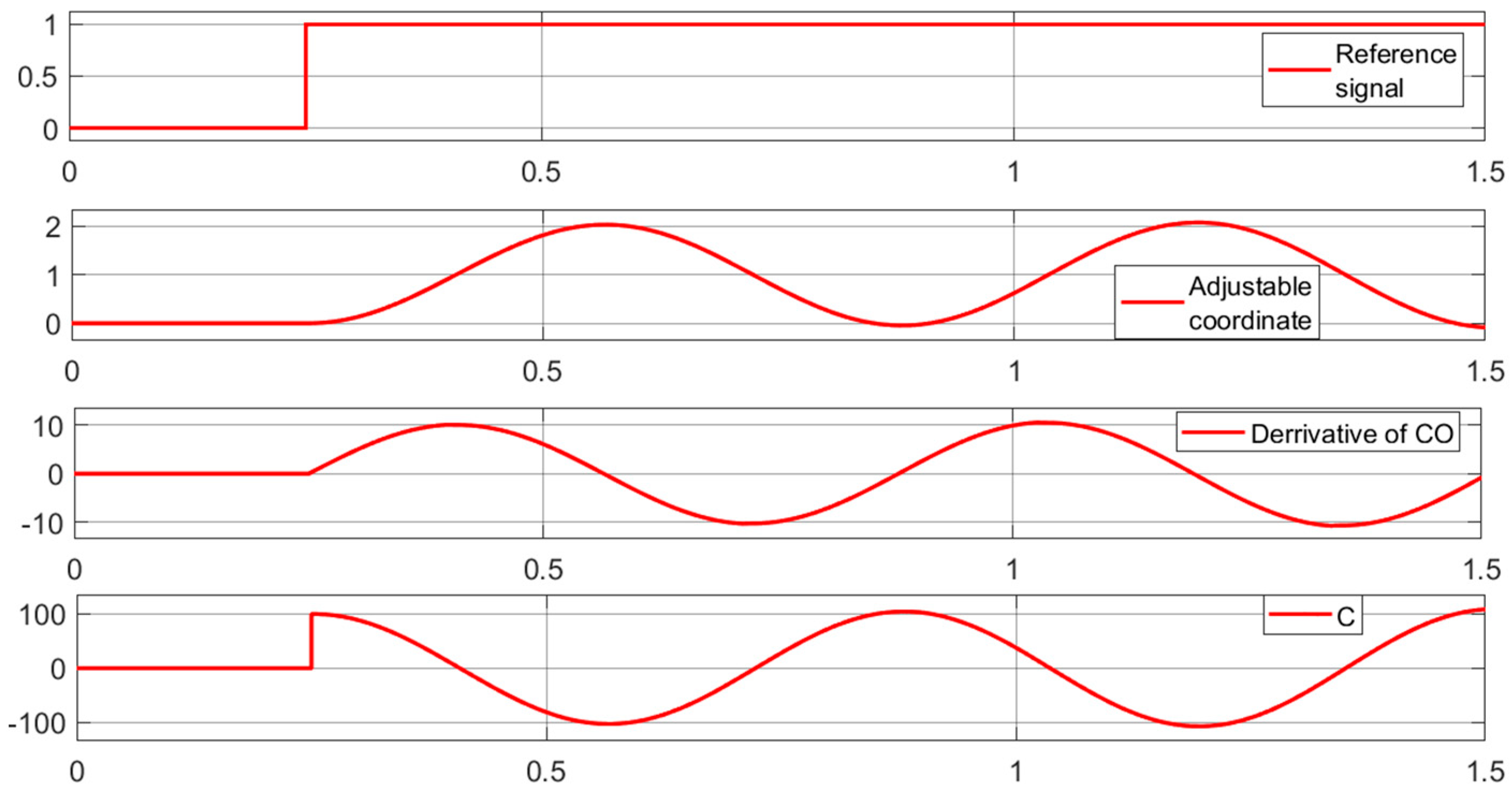
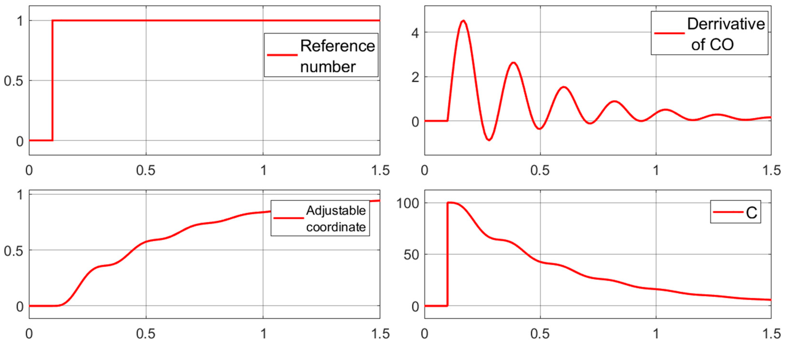
Figure 6 shows a diagram of the model in the MatLab (ver R2017b) software environment.
Control object and two inertial links with small time constants (—0.001s.
Controller with K = 100.
The forcing link with a time constant forms the sliding trajectory.
Diagram 1—reference signal;
Diagram 2—adjustable coordinate;
Diagram 3—derivative of the adjustable coordinate;
Diagram 4—increased mismatch between the setting signal and the controlled coordinate.
In the first experiment (
Figure 7), the parameters of the slip former are the time constant
and
.
Condition (2) is not satisfied. The process of changing the output coordinate is self-oscillation of all coordinates, there is no sliding, and the LFCs are similar to those shown in
Figure 2b.
In the second model, the parameters of the link forming the slip are changed—
. Condition (2) is satisfied.
The process shown in
Figure 8a is close to ideal sliding (“quasi-ideal” sliding).
Figure 8b shows processes in the same model with small time constants in the control object increased to 0.01 s. The amplitude increased and the frequency of oscillations of the derivative of the controlled variable decreased (diagram 3). The diagram of the controlled variable (diagram 2) remained virtually unchanged. The LFCs are similar to those shown in
Figure 2c. The phase shift of the equivalent link reaches a value of −90 at a large but finite frequency
.
Simulation confirmed the validity of the condition for the existence of slip in the system constructed according to the scheme in
Figure 1, in which the sliding trajectory has an order lower than the control object by 2 or more orders of magnitude. In this case, the condition for the existence of slow sliding processes and real, fast oscillations around the sliding trajectory with finite amplitude and frequency is satisfied.
For most electric drives, fast movements with the parameters presented in
Figure 8 will be acceptable. But for drives with high precision requirements, it is necessary to obtain a mechanism for reducing the amplitude and increasing the frequency of fast movements. One of the effective methods is the use of cross-links.
4.1. Cross Connections and Quasi-Ideal SM
In control systems for real electric drives, the sliding path former link is most often a first-order forcing link, the time constant of which is determined by the requirements for the speed of the drive. The control object simultaneously contains several inertial links with small time constants, except for the second-order integrating link. In this case, it is quite difficult to accurately determine the sliding trajectory equation using an equivalent control method [
1,
2,
3,
4,
7,
8,
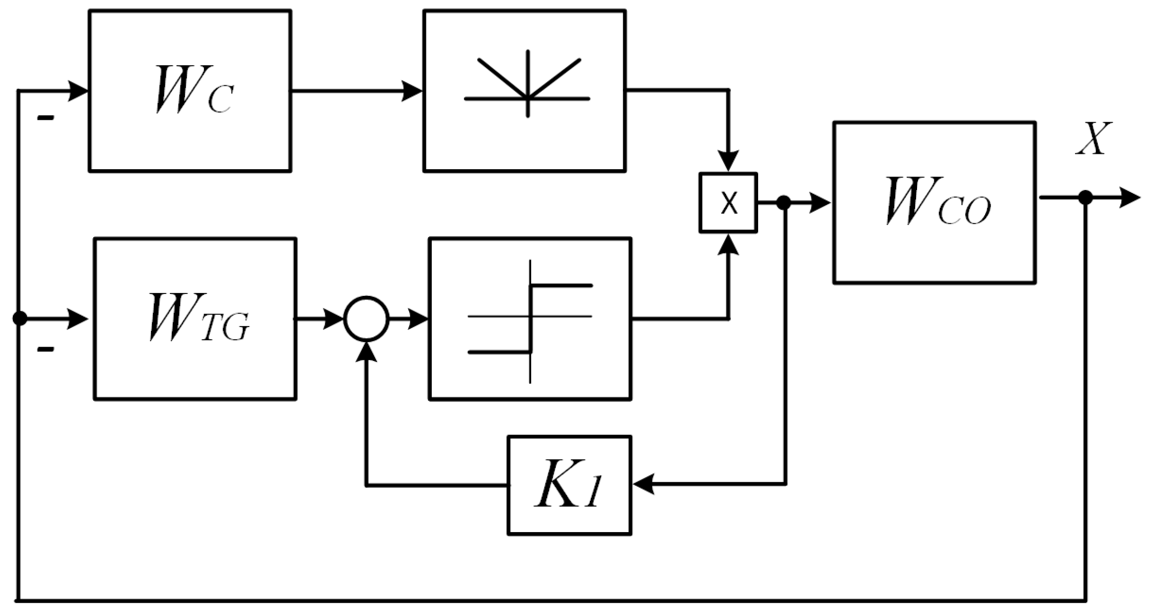
9]. Experiments have shown that for such a system, cross-coupling based on the control signal of the electric drive—the control signal or the voltage at the motor armature—will be effective.
This relationship is shown in the VSS diagram (
Figure 9) and in the substitution diagram (
Figure 10).
This signal, in relation to the output signal X, will be a forced signal with the required parameters that ensure the fulfillment of the sliding conditions (4) or the stability of the equivalent circuit.
Taking into account the connection, the condition will take the form (5).
Since condition (2) will be met, the sliding will be very close to ideal along the slow coordinate; the fast ones will have a minimum amplitude (
Figure 11) close to 0.
Cross-coupling defines the feedback LFC as the sum of the output signal of the high-order link and cross-coupling—that is, it excludes small delays and delays from the formative switching signal, which appear at high frequencies, as follows from the LFC (
Figure 11).
Specifically, the sliding trajectory will have a more complex structure and frequency characteristic.
The conditions for sliding and stability of the equivalent circuit will take the form
For a system with significant elasticity and nonlinearities in the high-frequency zone—that is, the frequency of elastic vibrations—rapid movements will form around a surface formed by other coordinates, which are more reliable, and in the zone of slow movements around adjustable coordinates—speed and movement.
4.2. Simulations Confirming the Effectiveness of Cross-Coupling
Figure 12a shows a cross-coupled VSS model and transient processes with a real sliding process with a coupling coefficient
equal to 0 (
Figure 12b).
Figure 12c shows processes with a coefficient
equal to 0.01, which makes the process quasi-ideal—without oscillations around the slip line in the presence of high-order links in the control object. It was not possible to obtain a similar result in an arbitrary-order VSS without cross-coupling [
17,
18].
Figure 13 shows the processes in the system with increased “small” inertia. We increase the time constant of the inertial link to 0.02 s.
The process has remained almost unchanged, with the exception of slowing down the approach to the sliding path.
In
Figure 14, the same time constant (
) increases to 0.05 s.
Low-frequency oscillations with a large amplitude appear, and sliding conditions are violated in the low-frequency zone (analogous to the state shown in
Figure 2b).
To fulfill the conditions for the existence of sliding processes, the time constant of the sliding trajectory () was increased to 0.5 s.
By increasing the time constant of the sliding trajectory, we increase the performance margin of the VSS, which was defined earlier as the ratio of the real to the boundary one .
Low-frequency conditions are met, the frequency of oscillations around the trajectory increases, and the amplitude decreases (
Figure 15).
When we increase the cross-coupling coefficient, the oscillation amplitude decreases and the frequency increases (
Figure 16).
In
Figure 17, showing the processes with an increase in the cross-coupling coefficient to 0.05 s, the time of the transition process does not change and the amplitude of the oscillations decreases to almost 0. Such processes in real ACS with plant parameters corresponding to the model in
Figure 6 are close to ideal and are unattainable for ACS with linear controllers, for example, PID controllers [
19,
20].
Thus, the possibility of synthesizing SMs close to ideal has been confirmed. With increased high-order inertia without increasing the order of the sliding trajectory, the cross-coupling is responsible for oscillations around the sliding trajectory because it contains high-order components. The low-frequency trajectory does not change. Thus, by increasing the cross-coupling coefficient , we improve the parameters of fast movements without increasing the order of the sliding trajectory.
4.3. Simulation in Equivalent Circuit
The stability of the equivalent circuit is also improved, since the high-frequency zone of the link is excluded from the operation of the circuit. This improvement is reflected by a decrease in the range of rapid movements.
Figure 18 shows a model of the equivalent circuit of a system with sliding, and
Figure 19 shows stable processes with changing parameters of self-oscillations in full accordance with the provisions of the article—self-oscillations reduce the amplitude and increase the frequency with the introduction of cross-coupling (
), which reduces the sliding amplitude to the parameters of quasi-ideal sliding.
Figure 20 shows the processes in the equivalent circuit with an increased time constant of the control object
in
Figure 20a, an increased time constant of the slip former
in
Figure 20b, and with increased cross-coupling coefficients
in
Figure 20c,d.
The diagrams show that the cross-coupling coefficient affects only the parameters of high-frequency oscillations of fast movements without affecting the parameters of slow movements.
The simulation confirms the frequency criteria for the existence of slip in systems with control objects of a higher order than the sliding trajectory equation. Simulation also confirms the possibility of creating quasi-ideal sliding in electromechanical systems in which high-order links are taken into account by links with low inertia. The simulation results in the original VSS are shown in
Table 1, and the processes in the equivalent circuit are shown in
Table 2.
Simulation allows us to study detailed changes in the parameters of control systems, change individual parameters in the required range, and track their impact. It is very difficult to change all the parameters of the control object in detail, as is performed in the proposed article. For this reason, such studies attach special importance to simulation.
4.4. Experiments
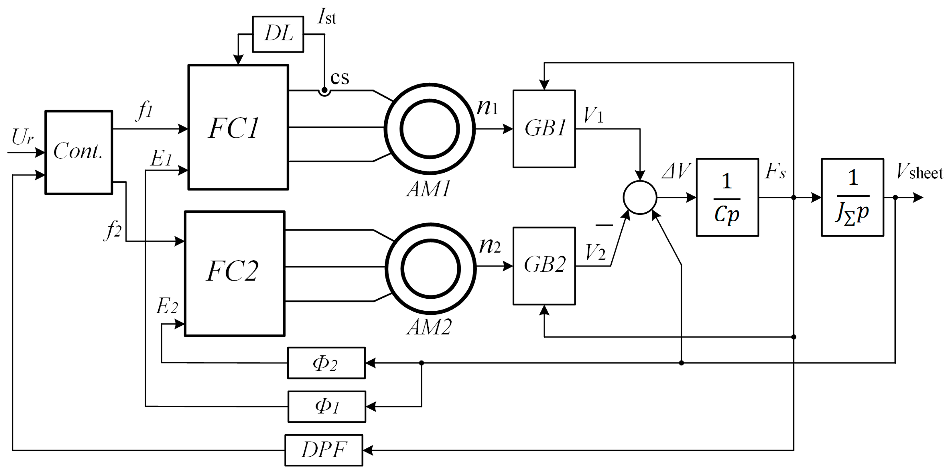
An example of correction of discontinuous processes in the control of electromechanical automatic control systems is a complex of asynchronous electric drives with frequency control of transport mechanisms, as discussed in articles [
21,
22]. When transporting sheet materials, the moment of “double” sheet gripping occurred, when two drives simultaneously acted on the sheet. The drive of the pulling roll experienced oscillatory influences associated with the final rigidity of the transported material. These influences disrupted the drive control, which, in the absence of a “double” grip, was extremely smooth and monotonous.
Double sheet gripping was always accompanied by an oscillatory transient process, which can be interpreted as discontinuous control with a large amplitude of damped “fast movements”. It should be noted that according to the technology performed by the mechanisms on this line, such processes were unacceptable since they led to uneven processing of the transported material. Diagram of a complex of electric drives interconnected through transportable non-rigid material is shown in
Figure 21.
Figure 22 shows diagrams of the processes of the moment developed by the pulling drive with a double grip. None of the traditional management methods gave the desired result. Transient oscillatory processes were preserved under scalar (a), vector sensorless (b), and vector closed (c) controls. Only the introduction of a dynamic positive connection for the developed torque made it possible to significantly reduce this oscillation, as follows from
Figure 22d. In this case, the dynamic coupling reduces the amplitude of rapid movements in the same way as cross-coupling in sliding systems. These studies are described in detail in [
22].
5. Results Discussion
In recent years, there has been significant interest in systems with a variable structure with sliding processes [
7,
8,
9,
10] due to the fact that these systems are capable of providing high-precision dynamic transient processes in control systems with variable parameters—that is, with uncertainties. However, the main approaches remain the same: the entire analysis is based on a description of the behavior of control systems in the state space. This requires a detailed description of the object controlled by differential equations. In real technical systems, it is not always possible to obtain such equations. This is a significant limiting factor for the widespread implementation of systems with variable structure in real engineering systems.
In a number of works, the authors of this article proposed frequency methods for analyzing the conditions for the existence of slip in systems with a variable structure.
This article also shows the connection between the sliding conditions in systems with nonlinearities and the stability condition in the nonlinear equivalent circuit of the original system. The simulation showed both the effectiveness of systems with sliding and the effectiveness of the proposed criteria for the existence of sliding processes.
6. Conclusions
The paper presents the frequency conditions for the existence of sliding modes in control systems of arbitrary order with a sliding trajectory described by a first-order forcing link. Process simulation was carried out, which confirmed the frequency criteria.
It is shown that the sliding condition in systems with a variable structure (VSS) corresponds to the conditions of absolute stability proposed in the work of the nonlinear equivalent circuit of the VSS.
It is shown that cross connections for the formation of a switching trajectory (trajectory of a sliding process) will allow the formation of a sliding process close to ideal (with an infinitely small amplitude and an infinitely large frequency of fast movements) in a system with a high-order control object and first-order switching trajectory.
The presented results of simulation in VSS with a fourth-order object confirm the main results and provisions of the article.
These provisions can become the basis for engineering criteria for the existence of sliding processes in real electromechanical systems.
