Abstract
The inter-shaft graphite seal is a common structure in the dual-rotor system, and may generate nonlinear lateral excitation when there is large relative angular motion at the seal position. This paper represents the first attempt to study the nonlinear behaviors of a dual-rotor system with inter-shaft graphite seal excitations. First, an excitation model of the inter-shaft graphite seal is proposed by the analytical method. This model is then introduced into the beam finite element model of a dual rotor system, and the dynamic equations of the whole system are finally obtained. The vibration responses under the effect of the inter-shaft seal are clarified by analyzing 3D waterfall plots, rotor orbits, and time and frequency domain waveforms. The results show that the inter-shaft seal can lead to vibration coupling between HP and LP rotors. The axial spring stiffness and contact end face friction coefficient of the graphite seal have a significant effect on rotor vibration. When those two parameters are small, only coupling vibration phenomena can be observed, i.e., the rotation frequency of one rotor can be observed in another rotor vibration. With the increase in axial spring stiffness or contact end face friction coefficient, multiple modes of LP and HP rotors are excited, which dominates the vibration behaviors of the dual rotor system.
MSC:
37N15; 74H45
1. Introduction
An aero-engine is a type of high-speed rotating thermodynamic machinery. It consists of rotor structures and rotor-static sub-structures that have numerous contact end faces. The gaps between these contact surfaces can lead to the loss of parts and components, as well as decrease the performance and efficiency of the engine [1,2]. To address these issues, sealing technology is used to improve engine performance, enhance component lifespans, and increase engine efficiency [3].
Mechanical sealing relies on elastic elements to tighten the contact surfaces [4,5] and prevent the flow of fluids through tiny gaps. The performance of the sealing structure plays a crucial role in aircraft engine performance. Scholars have conducted a series of studies on structural parameters, optimization design, and the mechanical behavior of mechanical seals. He developed a dynamic model to study the effect of dynamic parameters such as stiffness on the mechanical end-face seals [6]. Long analyzed the effect of parameters like sealing surface width on the characteristics of the end face of the contacting mechanical seals through simulation calculations [7]. Zhou investigated the radial gap sealing performance of graphite rings. The results show that the radial contact stress of graphite rings is linearly related to the axial load but unaffected by density [8]. The effect of spring pressure on the friction characteristics of balanced mechanical seals has also been explored [9]. Chen analyzed the nonlinear contact characteristics and sealing performance mechanisms of certain types of sealing rings by using the finite element method and found that contact stress steadily increases with pressure and friction coefficient [10]. Quantitative analysis of sealing performance has been conducted based on a multi-scale sealing contact model, such as contact area, contact pressure distribution, and contact state [11]. Zhang investigated the effects of pressure, friction coefficient, and other parameters on the mechanical behavior and sealing performance of a certain type of sealing device, and revealed its deformation and stress distribution characteristics [12].
The above research mostly focuses on the seal itself. However, in actual high-speed rotating machinery, the seal structure is used in conjunction with the rotor structure, static sub-structure, and so on. The excitation load produced by the seal structure on the rotor structure can lead to changes in the dynamic characteristics of the rotor system. And the issue has received attention from several scholars [13,14]. Wileman, J., investigated the dynamic behavior of two flexible rotors, and also studied the effects of rotor dynamics coefficients such as damping and stiffness [15,16,17]. In order to solve the steady-state response of the mechanical end seal of the flexible rotor, An Sung Lee used a complex extended transfer matrix method to analyze a complete dynamic analysis of the seal friction system, including the effects of shaft inertia, liquid film, secondary seal, and axial excursion of the rotor’s center of mass [18]. Shet calculated the dynamic response of the rotor system by considering the radial growth effect of the seals at different pressure ratios. His study also emphasized the effect of the seals on the whole rotor system [19]. In order to address the problem of friction caused by the seal between the shafts in the dual rotor structure, Ling [20] carried out a study on the rotor dynamics modeling and dynamics characteristics considering the friction of the seal between the shafts. The results showed that reducing the coefficient of friction and other parameters can significantly reduce vibration and improve the stability of rotor operation.
Although more exploration has been carried out on the dynamic characteristics of the rotor-sealing system, aero-engines involve various types of sealing structures with different working principles and impacts on rotor dynamics [21]. A grapghite-end-face seal, as a kind of contact sealing structure, mainly uses axial springs, such as the pressure of the compensating mechanism, to realize the seal. It is a more ideal sealing device for modern aero-engines and widely used in aero-engine bearing cavities and other structures [22,23,24]. However, the compression force may change and become uneven accompanying the rotor’s vibration, which produces the nonlinear excitation force and leads to the complicated behaviors of the rotor’s lateral vibration. To aim at this problem, Yu built the dynamical model of the rotor system with a graphite seal and analyzed the effect of this nonlinear excitation on the rotor’s vibration [25]. In addition to the rotor-stator structure, graphite seals are also used between the inner rotor and outer rotor of the dual-rotor system, as shown in Figure 1. Different from the rotor-stator structure, the graphite seal in a dual-rotor system can lead to the coupling of two rotors, which will bring about more complex dynamic characteristics. However, to the best of our knowledge, there is a lack of sufficient research in this area.
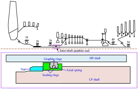
Figure 1.
The structure schematic of the dual-rotor system and inter-shaft graphite seal.
The main purpose of this paper is to reveal the influence of the inter-shaft graphite seal on the dynamic behavior of the dual-rotor system. Considering the structural characteristics of the inter-shaft seal, the nonlinear excitation of the inter-shaft seal is established based on the mechanical analysis. Then. the whole dynamical equation is obtained by introducing this excitation model into the beam finite element model of the dual rotor system. Finally, a comprehensive analysis is conducted on the vibration response characteristics of the dual-rotor system under various parameters.
2. Model Description of a Dual-Rotor System with an Inter-Shaft Graphite Seal
Figure 1 depicts a typical configuration of an aero-engine dual rotor, which has a graphite seal between the high-pressure (HP) and low-pressure (LP) rotor shafts. The LP rotor adopts a 0-2-1 support scheme, i.e., there is 0 support before the fan structure, 2 supports between the fan structure and the turbine structure, and 1 support after the turbine structure. The HP rotor adopts a 1-0-1 support scheme, i.e., there is 1 support before the compressor structure, 0 support between the compressor structure and the turbine structure, and 1 support after the turbine structure. To prevent gas flow between the front and rear cavities, the dual-rotor utilizes a graphite seal between the two shafts. The sealing structure comprises two sealing rings, two graphite rings, axial compression nuts, and axial springs. The two sealing rings are sequentially placed on top of the LP shaft and tightened by the nuts. The two graphite rings are axially placed in the grooves between the two sealing rings. The axial spring between the graphite rings provides the axial compression force between the end surfaces of the graphite ring and the sealing ring. The graphite ring is assembled onto the HP shaft by interference fit. When the HP rotor rotates, the graphite ring also rotates at the same speed under the effect of the friction force caused by the HP shaft.
2.1. Finite Element Modeling of a Dual-Rotor System
The dual-rotor system is modeled using the beam finite element method. The rotor possesses complicated structural characteristics, including the shaft system, drum, conical shell, blade disk, and so on. For the rotor shaft and drum structure, an equal cross-section beam element is employed in the modeling. For the conical shell structure, the variable cross-section beam element is utilized. The blade disk structure is simulated using the mass element, and the supporting structure is represented by the spring element. The cross-section parameters of each beam unit are derived from the dimensional parameters of the actual structure. The mass elements have the same mass and moment of inertia as the blade disk. The stiffness coefficients of the spring elements correspond to the static stiffness of the actual supporting structure. The simplified modeling process of the beam element for the complex dual rotor structure can be referred to in our previous work. The established beam element model of the dual-rotor is shown in Figure 2. The model consists of 59 beam elements, 21 mass elements, 5 spring elements, and 64 nodes. It should be noted that the beam element is a one-dimensional line element, and the purpose of Figure 2 is to visualize the cross-section of the beam, the location of the mass element, and the location of the spring element.
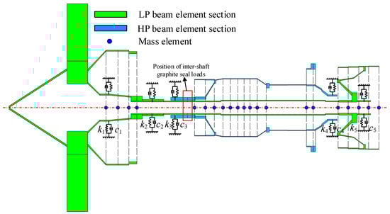
Figure 2.
Schematic diagram of simplified beam elements for HP and LP rotors.
2.2. Nonlinear Modeling of Inter-Shaft Graphite Seal
For the inter-shaft graphite seal depicted in Figure 1, the left and right contact faces between the graphite ring and sealing ring have a similar mechanical behavior. Thus, we use one side of the contact face to illustrate how lateral excitation is generated during the rotor’s vibration process. When the rotor rotates, the relative motion occurs between the graphite ring and the sealing ring. In the absence of rotor vibration, the compression force between the graphite ring and sealing ring is uniform. In this case, the sum of friction forces is zero. When the rotor vibrates in the lateral direction, axial relative motion occurs between the graphite ring and sealing ring. This leads to an uneven distribution of the compression force, as illustrated in Figure 3. Specifically, the contact pressure of the upper half of the contact face is reduced while the contact pressure of the lower half of the contact face increases. The uneven distribution of the contact pressure results in the uneven distribution of the friction force at the contact face, which further generates a lateral excitation force, as presented in Figure 3. This lateral force is related to the sealing parameters (axial spring stiffness, friction coefficient, and compression force) and lateral vibration of two rotors and can lead to the vibration coupling of the LP rotor and the HP rotor.
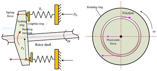
Figure 3.
The lateral force of the inter-shaft seal when rotor vibrates.
Based on the aforementioned analysis, the mechanical model of the inter-shaft seal is built, as shown in Figure 4. The seal contact behavior is simulated by a spring-moving ring element. The spring element is evenly distributed along the circumference. The axial stiffness of the spring element is , whose value is twice the value of the spring axial stiffness shown in Figure 1. The stiffness of the spring element in other directions is not considered. One side of the spring element connects the HP rotor, while another side connects the graphite ring. An initial compression force is applied to the spring element. Because of the initial compression force, the graphite ring connecting the HP rotor contacts the sealing ring connecting the LP rotor. To facilitate the analysis, the contact between the graphite ring and the sealing ring is assumed to be a line contact. The contact radius is , and the friction coefficient is . The rotation speeds of the HP rotor and the LP rotor are and , respectively. In this model, we only model the contact on one side. The contact force on another side is approximately the same since those two contact faces are close in axial position and have the same contact behaviors.
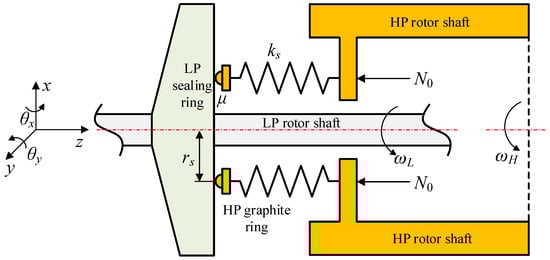
Figure 4.
Mechanical model of the inter-shaft seal in dual-rotor system.
If the dual-rotor system has no vibration, the contact pressure between the HP and LP sealing rings is evenly distributed. During this period, the lateral load at the contact face is zero. In this case, the compression displacement of the spring element is:
When the dual-rotor system vibrates, the contact behaviors and contact positions of the LP sealing ring and the HP graphite ring will change. Simultaneously, the compression displacement of the spring element along the circumferential position also changes. Thus, the contact pressure between the HP and LP sealing rings exhibits non-uniform distribution characteristics, as shown in Figure 5. For any circumferential position , a very small contact region is chosen. The corresponding axial displacement due to the vibration of the dual-rotor is:
where and are the axial displacements at position α caused by the vibration of the LP rotor and the HP rotor, respectively. , , , are the lateral-translational and the lateral-angular displacements of the LP rotor in the horizontal and vertical directions. , , , the lateral-translational and the lateral-angular displacements of the HP rotor in the horizontal and vertical directions. Due to axial displacement, the contact pressure corresponding to the region at the circumferential position α is as follows:
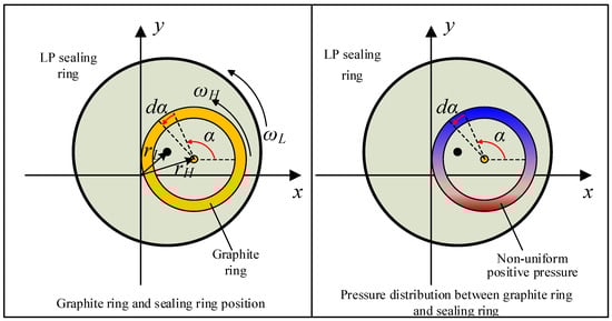
Figure 5.
Schematic diagram of relative motion and pressure distribution between LP sealing ring and graphite ring.
As a result, the friction force at the contact surface corresponding to the region can be obtained based on Coulomb’s friction law:
where is the unit direction vector whose direction is opposite to the direction of the relative motion velocity at the contact face. For the region at the circumferential position , the relative motion velocity can be obtained by the following expressions:
where and are unit vectors in the and directions, respectively. According to Equation (5), can be obtained as follows:
Substituting Equations (5) and (6) into Equation (4) and decomposing the friction force in and directions, one can obtain:
The above two expressions are the friction forces applying to the LP rotor. The friction force applying to the HP rotor can then be obtained as , through Newton’s third law. In addition to the friction force, the non-uniform contact pressure produces a bending moment on the rotor. The expression of the bending moment produced by the small region dα at the circumferential position is shown in Equation (9):
where and are the bending moments applying to the LP rotor. and are the bending moments applying to the HP rotor. Integrating Equations (7)–(9) along the circumferential direction, the total force and moment generated by the inter-shaft seal on the LP rotor and HP rotor are shown in Equations (10) and (11), respectively:
2.3. Governing Equation of the Whole System
By introducing the above nonlinear excitation model and the unbalance model into the finite element model of the dual-rotor system, the governing equations of the whole system are obtained, as shown in Equation (12). The position of the excitation is marked in Figure 2. The expression of unbalanced force can be found in many rotors’ dynamic textbooks22.
In the above equations, , , , and denote the mass matrix, damping matrix, gyro matrix, stiffness matrix, and displacement vector, respectively. Additionally, and denote the unbalanced excitation vector and the seal excitation vector, respectively. The damping matrix is formulated using the proportional damping form . The classical Newmark numerical integration method is employed to solve the dynamic equations in this paper.
2.4. Modal Characteristics of the Dual-Rotor System without External Excitation
When ignoring the inter-shaft seal, HP and LP rotors can be regarded as two independent rotors, and the modes of the LP and HP rotors can be determined separately, as shown in Figure 6. There are three-order and two-order critical speeds for the LP and HP rotors below the operating speed, respectively. The values of the critical speed are summarized in Figure 6. The corresponding modal shapes at the operating speed are presented in Figure 7. Because the forward whirl (FW) modal shapes are similar to the backward whirl (BW) modal shapes in the same order, only the FW modal shapes are presented.
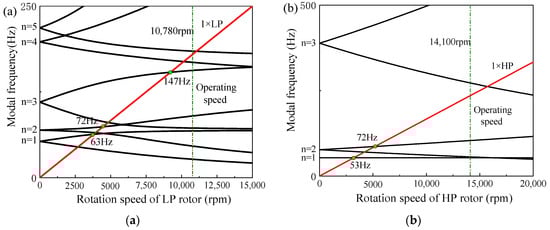
Figure 6.
Campbell diagram of the (a) LP rotor and (b) HP rotor, respectively.
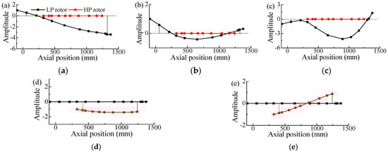
Figure 7.
Modal shapes of (a) n = 1+, (b) n = 2+, (c) n = 3+ for the LP rotor, (d) n = 1+, and (e) n = 2+ for the HP rotor under the no inter-shaft rub-impact condition.
3. 3D Waterfall Plot Analysis of the Dual Rotor System
3.1. Influence of Axial Spring Stiffness
For the parameters and N, the steady-state vibration responses of the 2# and 3# supports are respectively obtained for different axial spring stiffness N/m, N/m, and N/m. The results are depicted in Figure 8. When N/m, the frequency domain response of the 2# support only contains the LP rotational frequency component fL, which is similar to the result without the influence of the inter-shaft seal. However, the frequency domain response of the 3# support includes not only the HP rotational frequency component fH but also fL and the 1st FW modal frequency of the LP rotor fnL1+ over a wide range of rotational speeds. This indicates that the HP and LP rotors are vibration coupled under the influence of the end seal. When N/m, the frequency domain response of the 2# support still mainly contains the fL component. However, the frequency domain contents of the 3# support include not only fH, fL, and fnL1+ components but also a significant 2nd FW modal frequency component of the HP rotor, fnH2+. Meanwhile, the HP rotor’s vibration in this case is primarily dominated by 2nd modes since the corresponding amplitude is highest. When N/m, the effect of the inter-shaft seal on the responses of both the LP and HP rotors is more significant. In the whole speed range, the frequency domain contents of the 2# support contain multiple modal frequency components, including fnL1−, fnL5−, and fnH2+. Among them, the 5th BW mode dominates the LP rotor’s response. For 3# support, one can also observe multiple modal frequencies of both LP and HP rotors, among which the fnH2+ component has the largest amplitude. The above phenomena indicate that the dual-rotor system seems to suffer instability when axial spring stiffness is very high. A similar instable problem has been reported before in many single-rotor systems [26,27,28]. The reason is that the dry friction force generated by the seal structure does positive work on the rotor system and increases the rotor’s energy. When the work carried out by the friction force exceeds the dissipation of the rotor’s original damping, then the rotor system becomes instable, and multiple significant modal frequencies can be found in its response.
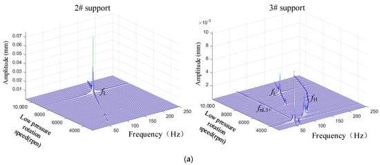
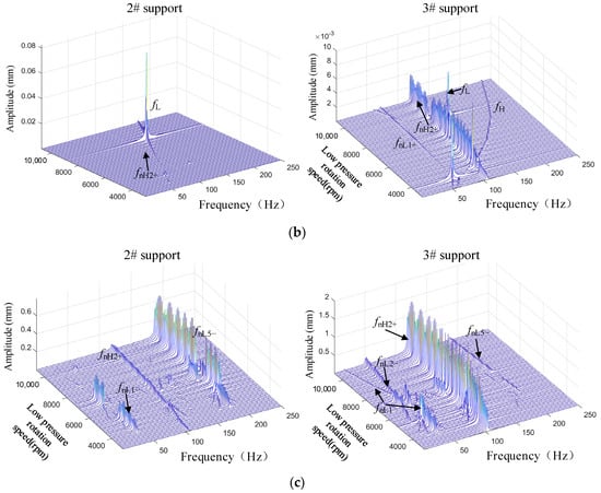
Figure 8.
Waterfall diagram of dual rotor vibration with different axial stiffness of inter-shaft seal: (a) ks = 107 N/m, (b) ks = 2 × 10⁷ N/m, and (c) ks = 5 × 10⁷ N/m.
From the above analysis, we can summarize: when the axial stiffness of the seal is small, the dual-rotor vibration is primarily dominated by the unbalanced excitation. If the axial stiffness is large enough, the seal excitation will lead to multi-order modal frequencies in the rotor’s vibration. The amplitudes of those modal frequencies can be even higher than those of the rotation frequencies, which means the vibration responses will be dominated by the rotor’s modes. It is worth noting that the vibration responses of LP and HP rotors are affected by different modes. The LP rotor’s vibration is mainly affected by the 5th BW mode, which corresponds to the bending vibration of the LP shaft. The HP rotor’s vibration is mainly affected by the 2nd FW mode, which corresponds to the pitching vibration of the HP rotor. For these two modes, the lateral-angular displacements at the seal position are all very high; therefore, these two modes are more sensitive to the seal excitation.
3.2. Influence of Different Friction Coefficients
The influence of the friction coefficient is analyzed in this section. In the following calculation, the axial spring stiffness () is assumed to be 2 × 10⁷ N/m and the compression force () is set at 50 N. Two different values for the friction coefficient (), namely 0.05 and 0.5, are considered. The results under the above parameters are shown in Figure 9. The analysis of the figure reveals the following findings: When , the steady-state response of the 2# support contains only LP rotational frequency components. For the 3# support, the steady state response contains significant fL and fH, as well as fnL1+. Additionally, one can observe the 3rd resonance excited by the LP imbalance and the 2nd resonance excited by the HP imbalance. When , the responses of the 2# and 3# supports are all dominated by the modes of the HP and LP rotors. The 2# support contains fnL1−, fnL3+, and fnL3−, as well as fnH2+, along with other combining frequencies, among them, fnL1− has the largest amplitude. 3# support frequency-domain response is dominated by fnH2+, with smaller amplitude frequency components fnL1− and fnH1+. From the above analysis, it can be concluded that when the friction coefficient is small, the vibration of the dual rotor system is primarily affected by unbalanced excitation. When the friction coefficient is high, the dual-rotor system transitions into modal vibration caused by the excitation of the inter-shaft sealing friction.
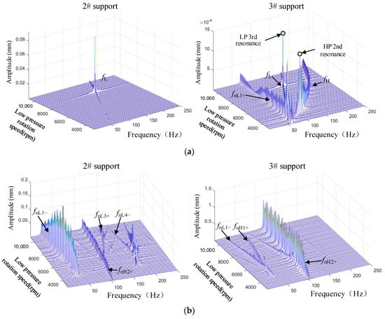
Figure 9.
Waterfall of dual rotor vibration under the influence of different end-face friction coefficients: (a) μ = 0.05, (b) μ = 0.5.
3.3. Influence of Axial Compression Forces
This section analyzes the effect of the initial axial compression force . In the following calculation, N/m, , and the initial compression force are 10 N and 100 N, respectively. The steady-state vibration response of the dual-rotor system is shown in Figure 10. The results reveal that when N, the steady-state response of the 2# support only contains fL, while the response of the 3# support includes both fL and fH, as well as fnL1+ and fnH2+. It is evident that the unbalanced excitation significantly affects both the HP and LP rotors. When N, the response of the 2# support still contains fL, while the response of the 3# support contains fL and fH, fnH1+, and fnH2+. It is important to note that the amplitude of the fnH2+ experiences a significant increase when N0 increases to 100 N, which means the vibration response of the HP rotor is primarily dominated by the 2nd FW mode. Furthermore, a comparison between N and N (see Figure 8b) demonstrates that the vibration response of both the HP and LP rotors is the same under these two initial compression forces. When the axial force exceeds a certain value, the dual rotor vibration response remains unchanged for the increasing initial axial compression force. Only in the case of a small initial axial compression force does the vibration response of the HP rotor change with the varying initial compression force.
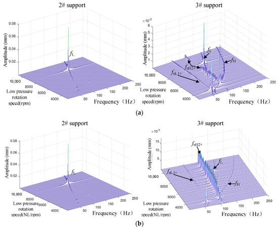
Figure 10.
Waterfall diagram of dual rotor vibration under different axial compression forces: (a) N0 = 10 N, (b) N0 = 100 N.
4. Typical Response Characteristics of the Dual Rotor System
The analysis in Section 3 demonstrates significant differences in the rotor’s vibration behavior when the inter-shaft seal has different mechanical parameters. This section focuses on the typical response characteristics of the dual-rotor system. Herein, the results under operating speed (LP rotation speed is 10,780 rpm and HP rotation speed is 1400 rpm) and different axial spring stiffness are chosen. Figure 11 shows the axis orbits, time domain responses, and frequency domain responses of the 2# and 3# supports when N/m. The red and green circles represent the whirl position at time and respectively, from which one can observe the rotor’s whirl direction. Under the given seal parameter, the orbit of the 2# support exhibits an elliptical shape. The whirl direction is counterclockwise, which is the same as the rotor rotation direction, which indicates that the LP rotor is in a FW state. In the frequency response, only the LP rotational frequency fL can be observed. For the 3# support, its orbit is more complex and irregular. Meanwhile, it also exhibits a counterclockwise whirling direction, which means the HP rotor is also in a FW state. The corresponding frequency-domain response mainly includes fL and fH, as well as fnL1+.
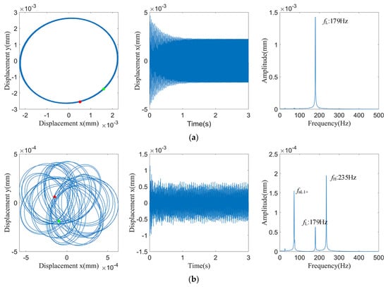
Figure 11.
When ks = 107 N/m dual rotor vibration response at a given speed, (a) 2# support and (b) 3# support.
When the spring stiffness is increased to N/m, the vibration responses of the dual-rotor system are shown in Figure 12. In the frequency domain of the 2# support, one can observe the main components, fnH2+ and fL. The steady-state vibration amplitude in the time domain exhibits the fluctuation characteristics, and the orbit approximately contains three non-coincident ellipses. From the whirling direction, we can see that the LP rotor is still in a FW state. For the 3# support, the orbit displays numerous non-coincident elliptic characteristics, and it is a FW. The vibration response in the time domain is extremely complex, while in the domain, the responses contain fL and fH and multi-order HP and LP modal components. Among them, fnH2+ in the response of the 3# support has a significantly higher amplitude compared to other components. Consequently, the rotor is primarily dominated by fnH2+.
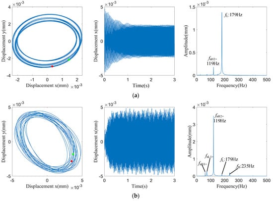
Figure 12.
When ks = 2 × 10⁷ N/m dual rotor vibration response at a given speed, (a) 2# support and (b) 3# support.
The spring axial stiffness is further increased to N/m, and the vibration responses are depicted in Figure 13. It is evident that the vibration responses of both the 2# and 3# supports first diverge and then stabilize at a high vibration amplitude. At steady-state, the vibration exhibits the pseudo-periodic feature. For 2# support, the steady-state amplitude is approximately 0.6 mm. One can observe fnL5−, fnH2+, fnL3+, fnL4+, and some combining frequencies (427 Hz: 2 fnH2++ fnL5−, 495 Hz: fnH2++2 fnL5−). It should be noted that the LP rotor is dominated by fnL5−; thus, the orbit whirling is in the clockwise direction. That means the LP rotor becomes a BW state in this case. While for 3# support, the frequency contents are fnH2+, fnL5−, and some combining frequency (51 Hz: 2 fnH2+ − fnL5−). Unlike the LP rotor, the HP rotor in this case is still in the FW state.
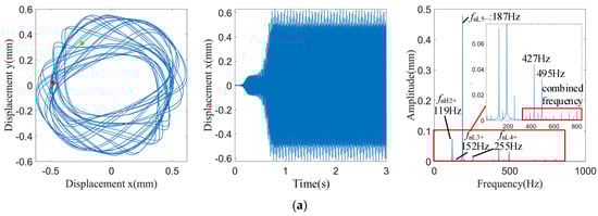
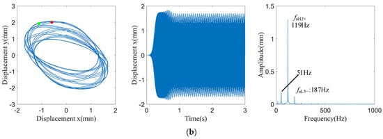
Figure 13.
When ks = 5 × 10⁷ N/m dual rotor vibration response at a given speed, (a) 2# support and (b) 3# support.
5. Conclusions
The nonlinear dynamic behaviors of a dual-rotor system with inter-shaft graphite seal excitations are investigated for the first time. An excitation model of the inter-shaft seal is proposed based on the deformation and force analysis. By combining the excitation model and beam finite element model of a dual rotor system, the dynamic governing equations of the whole system are built, and the vibration characteristics are revealed by analyzing 3D waterfall plots, rotor orbits, time, and frequency domain waveforms. The main conclusions are summarized as follows:
- (1)
- The lateral excitation caused by the inter-shaft seal is closely related to the relative angular motion between the HP and LP rotors. This relative angular motion results in non-uniform normal pressure and tangential friction pressure at the seal contact end face, which further generates a resultant force that can stimulate the lateral vibration of the rotor system.
- (2)
- The inter-shaft seal leads to the vibration coupling between two rotors. The rotation frequency component of one rotor can be observed in the vibration response of another rotor. Compared to the LP rotor, the HP rotor is more sensitive to the inter-shaft seal excitation since the modal vibration of the HP rotor is easier to excite.
- (3)
- Under the influence of the inter-shaft seal, the rotor may exhibit a complicated time-domain response. The frequency-domain response contains multi-order modal frequency components. In addition, the LP rotor consistently exhibits the FW state, while the HP rotor may transition from the FW to the BW state when the excitation of the inter-shaft is high.
- (4)
- Through the analysis of key parameters, the axial spring stiffness and contact face friction coefficient significantly affect the rotor vibration response, while the influence of axial compression force is less. When both spring stiffness and friction coefficient are small, the dual rotor vibration is dominated by unbalanced excitation. If the spring stiffness or friction coefficient is large enough, multiple modal components can be induced and play a leading role in vibration responses. At that time, the 1st and 5th backward whirl modes mainly dominate the LP vibration, while the 2nd forward whirl mode dominates the HP vibration. These three-order modes have large relative angular motion at the inter-shaft seal position and are therefore more likely to be excited.
Author Contributions
Conceptualization, P.Y. and C.W.; methodology, Z.J. and Q.Z.; investigation, S.X. and P.Y.; writing—original draft preparation, S.X.; writing—review and editing, P.Y., Z.J. and J.C.; supervision, P.Y. and Q.Z.; funding acquisition, P.Y. and C.W. All authors have read and agreed to the published version of the manuscript.
Funding
The authors would like to acknowledge the financial support from the National Natural Science Foundation of China (Grant Nos. 52372387, 52005252, and 52105130), the Jiangsu Province Natural Science Foundation (Grant No. BK20211187), the Aeronautical Science Foundation of China (Grant No. 2020Z039052007), and the Postdoctoral Science Foundation Project (Grant No. 2022M711615).
Data Availability Statement
The raw data supporting the conclusions of this article will be made available by the authors on request.
Conflicts of Interest
Author Sen Xiao was employed by the company Chengdu Aircraft Industry (Group) Co., Ltd. The remaining authors declare that the research was conducted in the absence of any commercial or financial relationships that could be construed as a potential conflict of interest. The [company Chengdu Aircraft Industry (Group) Co., Ltd-companies in affiliation and funding] had no role in the design of the study; in the collection, analyses, or interpretation of data; in the writing of the manuscript, or in the decision to publish the results.
References
- Huang, Q. (Ed.) Aero Engine Design Manual Volume 10; Engine Design Manual, Editor in Chief of the Editorial Committee; Aviation Industry Press: Beijing, China, 2001; Volume 10, pp. 248–252. [Google Scholar]
- Yu, P.; Hou, L.; Jiang, K.; Jiang, Z.; Tao, X. Dynamic modeling and nonlinear analysis for lateral–torsional coupling vibration in an unbalanced rotor system. Appl. Math. Model. 2024, 126, 439–456. [Google Scholar] [CrossRef]
- Hu, G. Research on the Application of Aeroengine Sealing Technology. Aeroengine 2012, 38, 1–4. [Google Scholar]
- Hao, M.; Li, Z.; Ren, B.; Wang, X. Mechanical Sealing Technology and Applications, 2nd ed.; China Petrochemical Press: Beijing, China, 2014; Volume 10. [Google Scholar]
- Lebeck, A.O. Principles and Design of Mechanical Seals; Huang, W.; Li, Y.; Wang, Y., Translators; Mechanical Industry Press: Beijing, China, 2016; pp. 1–13. [Google Scholar]
- He, W.; Wang, S.; Zhang, C.; Wang, J. Effect of simple harmonic vibration on the mechanical face seals of aero-engine pump. In Proceedings of the CSAA/IET International Conference on Aircraft Utility Systems (AUS 2018), Guiyang, China, 19–22 June 2018; IET: Stevenage, UK, 2018; pp. 1075–1080. [Google Scholar]
- Wei, L.; Fang, G.; Liu, Q. Effects of seal face width on the contact characteristics between the end faces for contacting mechanical seals. In IOP Conference Series: Earth and Environmental Science, Proceedings of the 2019 5th International Conference on Energy Equipment Science and Engineering, Harbin, China, 29 November–1 December 2019; IOP Publishing: Bristol, UK, 2020; Volume 461, p. 012060. [Google Scholar]
- Zhou, X.; Chen, C.; Li, J.; Wu, Y. Study on radial clearance sealing performance of graphite ring. J. Press. Vessel. Technol. 2021, 143, 031703. [Google Scholar]
- Sun, J.; Gu, B. Investigation into effect of spring pressure on performance of balanced mechanical seals. Chin. J. Mech. Eng. Engl. Ed. 2007, 20, 39–43. [Google Scholar] [CrossRef]
- Chen, G.Q.; Tan, J.P.; Wang, X.; Chen, H. 3D Nonlinear Contact FEM Analysis of U-Ring Seal Structure. Adv. Mater. Res. 2012, 510, 660–666. [Google Scholar] [CrossRef]
- Wang, R.; Liu, J.; Zhang, F.; Ding, X. An approach to evaluate the sealing performance of sealing structures based on multiscale contact analyses. J. Comput. Des. Eng. 2021, 8, 1433–1445. [Google Scholar] [CrossRef]
- Zhang, J.; Xie, J. Investigation of static and dynamic seal performances of a rubber O-ring. J. Tribol. 2018, 140, 042202. [Google Scholar] [CrossRef]
- Chen, S.T.; Wu, Z.Q. Rubbing vibration analysis for a counter-rotating dual-rotor system. J. Vib. Shock. 2012, 31, 142–147. [Google Scholar]
- Varney, P.; Green, I. Dynamic modeling of an eccentric face seal including coupled rotordynamics, face contact, and inertial maneuver loads. Proc. Inst. Mech. Eng. Part J J. Eng. Tribol. 2018, 232, 732–748. [Google Scholar] [CrossRef]
- Wileman, J.; Green, I. The rotordynamic coefficients of mechanical seals having two flexibly mounted rotors. J. Tribol. 1991, 113, 795–804. [Google Scholar] [CrossRef]
- Wileman, J.; Green, I. Parametric investigation of the steady-state response of a mechanical seal with two flexibly mounted rotors. J. Tribol. 1999, 121, 69–76. [Google Scholar] [CrossRef]
- Wileman, J.; Green, I. Steady-state analysis of mechanical seals with two flexibly mounted rotors. J. Tribol. 1997, 119, 200–204. [Google Scholar] [CrossRef]
- Lee, A.S.; Green, I. Rotordynamics of a mechanical face seal riding on a flexible shaft. J. Tribol. 1994, 116, 345–350. [Google Scholar] [CrossRef]
- Shet, V.V.; Sekhar, A.S.; Prasad, B. Dynamic Analysis of Rotor-Seal System Considering the Radial Growth Effect of the Seal. In Journal of Physics: Conference Series, Proceedings of the 2019 the 10th Asia Conference on Mechanical and Aerospace Engineering, Bangkok, Thailand, 26–28 December 2019; IOP Publishing: Bristol, UK, 2020; Volume 1510, p. 012002. [Google Scholar]
- Ling, W.; Wang, C. Nonlinear Dynamics of Dual-Rotor System in Aero-Engine under Rub-Impact Between Shafts. J. Propuls. Technol. 2023, 44, 176–188. [Google Scholar]
- Cao, S.; Chen, Y. A Review of Modern Rotor/Seal Dynamics. Eng. Mech. 2009, 26, 68–79. [Google Scholar]
- Ishida, Y.; Yamamoto, T. Linear and Nonlinear Rotordynamics: A Modern Treatment with Applications; John Wiley & Sons: Hoboken, NJ, USA, 2013. [Google Scholar]
- Li, Y.; Long, T.; Luo, Z.; Wen, C.; Zhu, Z.; Jin, L.; Li, B. Numerical and experimental investigations on dynamic behaviors of a bolted joint rotor system with pedestal looseness. J. Sound Vib. 2024, 571, 118036. [Google Scholar] [CrossRef]
- Shen, H.; Zheng, T.; Chen, Y. Improvement of Aero-Engine Sealing Technology. Gas Turbine Test. Res. 2011, 4, 51–55. [Google Scholar]
- Hou, L.; Yu, P.; Wang, C. Investigation on Nonlinear Behavior of a Rotor System with Friction Effect Due to End-Face Seal. In International Conference on Rotor Dynamics, Proceedings of the 11th IFToMM International Conference on Rotordynamics, Beijing, China, 18–21 September 2023; Springer International Publishing: Cham, Switzerland, 2023; pp. 11–33. [Google Scholar]
- Luo, Q.; Chu, B.; Xu, C. Experimental research for sub-synchronous vibration problems of hydrogen turbopump. J. Rocket. Propuls. 2014, 40, 14–19. [Google Scholar]
- Zhang, X.; He, H. Mechanism of subsynchronous vibration about turbopump rotor system. J. Propuls. Technol. 1999, 20, 41–45. [Google Scholar]
- Bai, C.; Xu, Q.; Zhang, X. Effect of seal and internal damping on dynamic stability of liquid hydrogen turbopump rotor system in rocket engine. Chin. J. Mech. Eng. 2006, 42, 150–155. [Google Scholar] [CrossRef]
Disclaimer/Publisher’s Note: The statements, opinions and data contained in all publications are solely those of the individual author(s) and contributor(s) and not of MDPI and/or the editor(s). MDPI and/or the editor(s) disclaim responsibility for any injury to people or property resulting from any ideas, methods, instructions or products referred to in the content. |
© 2024 by the authors. Licensee MDPI, Basel, Switzerland. This article is an open access article distributed under the terms and conditions of the Creative Commons Attribution (CC BY) license (https://creativecommons.org/licenses/by/4.0/).