Abstract
This study introduces a polyharmonic framework for analyzing the electromagnetic (EM) field generated by an oscillating point charge near a dispersive bulk of size comparable to the wavelength under study. We critically evaluate traditional approaches such as Liénard-Wiechert, Landau, and Raimond, and propose a Fourier representation of sources that simplifies numerical implementation and enhances analytical clarity. Our method effectively addresses the limitations of conventional models and is applicable to both relativistic and non-relativistic scenarios. It includes the oscillating point dipole fields, providing a comprehensive understanding of the EM field behavior. The Finite Element Method (FEM) is employed for numerical analysis, demonstrating the method’s adaptability to complex geometries. While offering significant insights, this study acknowledges certain limitations and outlines directions for future research.
Keywords:
electromagnetic waves; finite element method; harmonic decomposition; nanophotonics; numerical methods in electrodynamics MSC:
78A02; 78A35; 78A40; 78A45; 78A50; 78M10; 35Q60; 35Q61; 42A16; 46F10
1. Introduction
In this study, we investigate the electromagnetic (EM) field generated by a stiff oscillating charged particle in proximity to a nanosphere by utilizing the diffracted field formalism. Our primary objective is to elucidate the EM field produced by an oscillating particle in vacuo. Despite its seemingly academic nature, this problem has practical applications in various configurations, such as Hertz and Sommerfeld antenna studies [1,2,3,4]. Another example where this kind of source is used lies in the investigation of the potential generated by a charged point that is fixed in positionand oscillating in magnitude (as provided by ) in an inhomogenous cold plasma with no magnetic field [5].
In the context of nanoemitters and their interaction with plasmonic structures, Klimov et al. [6,7] treated an atom near a dielectric microsphere as a non-relativistic oscillator consisting of a stationary charge and an oscillating charge q. They highlighted the necessity of a quantum electrodynamics approach to ensure consistent calculation of photon emission, yet acknowledge that a classical electric dipole model can serve as a useful approximation [7]. This perspective was echoed by Lobanov et al. in their numerical study of a point dipole with a periodic array of Yagi-Uda nanoantennas, where they stated that “The exact description of photon radiation from quantum nanoemitters is very complicated. A convenient approximation is the model of an oscillating point dipole.” Similarly, Lassalle et al. modeled an excited two-level atom near a nanosphere as a harmonically oscillating point dipole [8]. This approach was adopted in [9] as well, where the study of a point electric dipole in a flat-slab composite structure was conducted. Thus, as described in various foundational texts, it is common practice to employ a far-field dipole approximation [2,10,11,12].
Remark 1.
However, the dipole approximation is only valid when dealing with the far field and for non-relativistic particles.
Thus, it is necessary to find a better way to describe the field generated by an oscillating charge . The immediate approach is to use the Liénard-Wiechert fields, which describe the fields produced by a moving charge in quite a compact form; however, their complexity renders them impractical from a numerical standpoint. Moreover, the methods proposed by Landau et al. involving a harmonic expansion of the delta and J.M. Raimond’s Taylor series approximation of the delta distribution [13] are limited both analytically and numerically, as discussed in Section 2.2.2 of this work.
To address these limitations, we introduce a harmonic decomposition of the source terms and ȷ. After establishing charge conservation, this method enables us to derive a harmonic representation of the electromagnetic fields. Our approach is distinguished by its analytical clarity and directness, allowing us to examine electromagnetic radiation without resorting to the common simplifications found in the existing literature, particularly the dipole approximation.
When the sources have been obtained in harmonic form, we use them as the incident field in the diffraction problem to obtain the diffracted field numerically based on a sphere and using the Finite Element Method (FEM) [14]. This choice is motivated by the flexibility of FEM in handling various geometries of the dispersive bulk, although in this case we have chosen a sphere for simplicity. Furthermore, our solution is presented in the time domain, moving away from the simplifying assumption of working in the harmonic regime.
The rest of this paper is structured as follows.
Section 2 lays the groundwork for our study, establishing the mathematical formalism of the diffracted field problem in Section 2.1. We then explore various methodologies for deriving the EM field produced by an oscillating charge in Section 2.2. This includes an analysis of the EM field generated by an arbitrary charge distribution and a critical evaluation of the Liénard-Wiechert, Landau, and Raimond approaches, highlighting their respective advantages and limitations.
In Section 2.3, we focus on developing a harmonic representation of the sources and demonstrating the conservation of charge. Section 2.4 is particularly significant, as it presents the polyharmonic construction of the electric and magnetic fields, complemented by numerical illustrations.
Section 3 presents the outcomes derived from employing the polyharmonic representation of the fields. Section 3.1 and Section 3.2 detail the computation of the far-field radiated power from the polyharmonic fields, showing its alignment with the numerical integration of the Poynting vector around the trajectory of the oscillating charge. Furthermore, Section 3.3 establishes that the oscillating charge cannot exceed the speed of light, thereby upholding the principles of Einstein’s theory of relativity. Building on these findings, Section 3.4 demonstrates how our polyharmonic solution encompasses the scenarios of a static monopole and a point dipole within a multipolar expansion framework.
Section 3.5 is dedicated to applying the polyharmonic representation of the fields as the incident field in the diffracted field problem. This leads to a formulation involving spatial coefficients obtainable through the Finite Elements Method (FEM). A numerical illustration of the total field is provided in Section 3.6.
Finally, Section 4 summarizes the main contributions of this work, discussing its limitations and outlining potential avenues for future research.
2. Materials and Methods
2.1. Mathematical Description of the Problem
The mathematical description of the interaction of an EM field with a time-dispersive bulk is provided by the Maxwell equations:
where represents the restriction of the fields, I corresponds to the total field outside the bulk, and corresponds to to the field inside the bulk. The constitutive relations are then , with the magnetic permeability in vacuo (i.e., the dispersive bulk has no magnetization) and , where
with being the vacuum electric permittivity, the Dirac’s delta distribution, and the causal electric susceptibility with its support within the bulk. The convolution is the one corresponding to the Fourier Transform convention in Appendix A. Thus, our new system of equations in terms of the () fields reads:
where is the speed of light in vacuo. The sources and represent the charge density and current corresponding to an oscillating particle; their explicit expression is provided in Section 2.3. The fields generated by these sources in vacuo are:
where the constitutive relations and have been used. Let us remark here that (,) is the incident field of our diffraction problem and that it is defined everywhere in space. The next step is to consider a new set of fields, defined as , which, in the present linear case, satisfy the system of so-called diffracted fields:
the sources of which are defined as
and
From these definitions, it is easy to see that charge conservation is satisfied. Note that the support of these new sources is within the bulk, and depends on the electromagnetic field generated by the oscillating particle. However, obtaining a handy expression of such a field requires very careful crafting, as shown in the next subsection.
2.2. The Search for the EM Field Generated by an Oscillating Charge In Vacuo
The problem of obtaining the electromagnetic field generated by a charged oscillating particle is a very important problem. This subsection begins with the very general approach of finding the (, ) fields generated by an arbitrary pair of charge and current distributions (, ). Usually, these solutions are provided by the so-called Jefimenko’s equations. However, we show that by following a similar method to the one in [15] for the far field approximations, it is possible to express the electric field mostly in terms of the current density. Next, we discuss a number of the efforts that have been made towards representing the EM field created by an oscillating charge.
2.2.1. The EM Field Generated by an Arbitrary Charge Distribution
First, we consider the system of Equations (1)–(4) (in the sequelae, the superscript 0 denoting the incident field radiated by the oscillating particle in free space has been removed to alleviate notations). By considering the Lorentz gauge, we can obtain the electric and magnetic fields (, ) using the expressions
where and are the retarded potentials [10,11]
with the retarded time and with . The next step consists of plugging the retarded potentials from Equations (13) and (14) into Equations (11) and (12) and then taking the appropriate derivatives. Nevertheless, this implies taking the time derivatives with respect to a function which is in terms of the retarded time . In order to avoid this difficulty and carry our calculations further, we propose using the Fourier transform in time (see Appendix A, denoting the Fourier transform of f) and then considering only the spatial derivatives. Starting by transforming the potential , we have
where . In a similar way the vector potential in the angular frequency domain reads
Before proceeding, the following identities are necessary:
and by combining Equations (17) and (18) we obtain
Equipped with these tools, it is quite easy to obtain by simply taking the curl of Equation (15):
after which, by taking the inverse Fourier transform, we arrive at the expression
where is the intermediate field and is the radiated field, which are respectively provided by the integrals
In order to obtain the electric field, it is necessary to consider the Fourier transform of Equation (11):
The first term on the right-hand side of Equation (21) is quite easy to calculate
while the second term is much trickier. Its derivation is as follows.
Up to this point, most textbooks, e.g., [10,11,16], simply take the inverse Fourier transform of Equation (23) and provide the electric field in terms of the derivative of the density of charges, obtaining the so-called Jefimenko’s equations [11,16]. Despite the straightforward nature of this derivation, we are going to carry the calculations further. The reason for doing this is laid out in the following subsection. For our purposes, the second integral in Equation (23) is already in optimum form, and we focus our attention on the integral defined within a bounded volume :
Notice that the integral we are looking for is the limit case when . Next, we make use of the continuity equation in the angular frequency domain:
By defining the function
the integral in Equation (24) can be written in a more compact way (omitting the , R, and dependencies) as follows:
Remark 2.
Notice here that the divergence is being taken with respect to the primed coordinates (hence, the prime superscript in ).
Due to the fact that we are working with Cartesian coordinates, it is possible to write
where denote the Cartesian unit vectors; then, we have
Each one of these integrals can be evaluated by means of the identity and the Green–Ostrogradsky theorem [17,18], as follows:
Taking the limit and following the assumption in [15] that ȷ is spatially bounded, the surface integral vanishes, leading to
The gradient (with respect to the primed coordinates) can be computed explicitly:
and we have
Plugging Equation (26) into Equation (25), we obtain
Before taking the inverse Fourier transform, we will try to express the term between square brackets (which we call ) in a more illuminating way. First, we rearrange as
Now, we consider the vector identity [18], and from this, we have
Then, can be seen as
Substituting this result into Equation (27) and then plugging that new integral into Equation (23), we finally arrive at the following expression.
From Equation (22), we can recognize the last integral as ; then, after taking the inverse Fourier transform, we obtain
where is the Coulomb field, the intermediate field, and the radiated field provided by the integrals
At this point, the reader may be wondering about the reason we have used all these extra steps, when Jefimenko’s equations already provide an explicit expression for the electric field. When dealing with Jefimenko’s equations, the magnetic field is in terms of the electric current , and the electric field is in terms of the distribution of charge [11,16]. This point of view, albeit intuitively very clear, makes it difficult to compare the terms corresponding to the radiation field. By carrying out the manipulations described above, we ensure that the intermediate and radiated electric and magnetic fields are all expressed solely in terms of the electric current. The utility of this approach is shown in Section 3.1.
2.2.2. The Different Approximations to the Oscillating Source Problem
- The Liénard-Wiechert’s Field approachThe academic problem of describing the and fields generated by a charged particle moving along a given trajectory , called the Liénard-Wiechert fields, has been studied in many books [10,11,15,19,20,21]. The basic idea is to consider a charge density and an electric current provided bywhere is a Delta distribution and . From here, there are many ways to tackle the problem of obtaining the and generated fields: Jackson [10] and Landau [19] considered an elegant formalism using quadrivector approach, while Panofsky [15] and Heald [20] used the so-called Liénard-Wiechert potentials, which can be obtained by direct substitution in Equations (13) and (14) and then carrying all the necessary derivatives. The deduction of the fields and following this procedure can be seen in [11]. For this subsection, we have decided not to follow any of these approaches, instead proceeding by direct substitution of the sources (31) and (32) into Equations (19), (20) and (28)–(30), that is:where we have introduced the usual following shorthand conventions:The procedure that is shown in Appendix C follows the ideas expressed by Heald and Marion in [21]; the main difference is that while Heald and Marion considered Jefimenko’s equations, we use Equations (33) and (37).
Remark 3.
We have decided to include the full deduction of the Liénard-Wiechert fields because, as far as we have seen, while this result has been quoted. the steps towards its obtention have not been shown. Griffiths simply states that the deduction is very difficult, and Heald and Marion say that it is necessary to perform heroic algebra. Therefore, we believe that it is important to show, as best we can, how to obtain one of the main results in classical electrodynamics.
- When the fields and have been provided by Equation (A25) and Equation (A19), that is,andwith , it might be easy to think that the fields produced by an oscillating particle could be retrieved by considering the specific trajectorywhere a and are the oscillation amplitude and angular frequency, respectively; nevertheless, as pointed out by Spohn in [20], the Liénard-Wiechert fields are less explicit than they appear to be. This is due to the fact that Equation (A25) and Equation (A19) depend on the retarded time, which is itself a solution of a transcendental equation (in general, a non-trivial one), namely,Let us note here that if the particle is at constant speed with a straight trajectory, then the Liénard-Wiechert fields can be found almost straightforwardly [11]. However, the solution to this problem when dealing with an oscillating charge, in this case the retarded time, is a function of the present time and the position ().
- The Landau Spectral Resolution ApproachIn the The Classical Theory of Fields, Landau et al. [19] considered that the fields produced by moving charges can be expanded as a superposition of monochromatic waves. Assuming that and have a Fourier integral representation, we can writeAccording to Landau, it is clear that each Fourier component of and is responsible for the creation of the corresponding monochromatic component of the field. Thus, it is natural to consider the following Fourier integral representations of the potentials and :In the sequelae, we only work with , as all the discussion applies to as well; substituting Equation (38) into Equation (13), we obtainComparing this last equality with Equation (39), we find thatRemembering that is the Fourier transform of , after some manipulations, can be written asNow, we consider the singular charge distribution, as in Equation (31), to obtainFrom the above expressions, it is evident that the right-hand side of the equation explicitly depends on the present time. This feature avoids issues related to the retarded time, which is a notable problem when using the Liénard-Wiechert fields. However, difficulties emerge when attempting to explicitly compute these integrals. This arises due to the fact that the particle’s trajectory, denoted by , is in principle unrestricted in its choice of any argument . Moreover, the exponential function in Equations (40) and (41) necessitates a sweep over all the values in .
- The Raimond’s Taylor Series Expansion ApproachIn [13] J.M. Raimond proposes another way to represent the charge density using a Taylor series expansion of the Dirac delta in the sense of distributions:where . In this way, the charge density can be rewritten:where the is the n-th charge density and is provided byThe reader may identify as the singular charge distribution of a -pole (i.e., monopole, dipole, quadrupole, etc.) [22,23]. Now, by considering the charge conservation, we can write:From this last expression, it can be seen that the current distribution can be written aswhere and (). From the above expressions, it is easy to see that there is a conservation of charge between the n-th current density and the n-th charge density for .Thus, it is possible to consider the charge distribution pairs in order to obtain the fields generated by an oscillating charge. In this case, the retarded potentials areIn the same fashion, we can write the vectorial magnetic potential asThe potentials in Equations (42) and (43) are expressed in terms of the present time t. However, the multiple derivatives that must be computed render the expressions impractical. One could argue that for a large value of , only a few terms are necessary to obtain a good approximation, as demonstrated in [13] by retaining up to the dipole term. However, this approach would essentially involve another far-field approximation [10]. In the following subsection, we present a more practical and elegant method for representing an oscillating charge.
2.3. Harmonic Decomposition of the Sources
As seen in the previous subsection, the Liénard-Wiechert fields are not the best way to obtain the fields produced by an oscillating particle. The main problem is that the source terms depend on the trajectory that describes the charge. For this reason, it is convenient to find a way to decompose the source terms in a polyharmonic way. This idea has been previously considered by Landau [19] and, as evident from Equations (42) and (43), by Raimond [13], albeit indirectly.
Remark 4.
However, as demonstrated in the previous subsection, the expressions derived from Landau’s and Raimond’s ideas are challenging to implement in practice. Thus, a new approach for describing the sources is necessary.
In this subsection, we propose another approach inspired in quantum mechanics, which can be summarized as follows: The superposition of waves spread in a certain domain can be seen as a particle. Physically, this means that a very localized source can be seen as the interference of a certain kind of waves. Mathematically speaking, we are looking to find a sequence such that we can have convergence in the sense of distributions to a Dirac delta [24,25,26]. It is worth noting that a similar concept was employed in [27,28] for the case of a charged particle in uniform motion.
2.3.1. Two Fourier Expansions for the Sources
Let us start our analysis by providing the charge density and its current density simply by
with and
and with out of charge conservation. Notice that and ȷ are not multiplied by the charge. It then turns out that the charge density is not harmonic, despite the harmonic motion of the particle. In other words, no complex function can be found such that .
Remark 5.
This is quite important, as in references such as [10,22] this is the starting point when representing an oscillating dipole.
Nevertheless, it is appropriate to notice that the distribution is a -periodic distribution. Thus, and can be expanded as a Fourier series (See Appendix B):
with
and
where are the Chebyshev polynomials of the first kind [29] and is the weight function
with a characteristic function.
2.3.2. Continuity Equation for the Harmonic Components of the Sources
In the previous paragraph, an expansion for and was linked by the so-called charge conservation, namely, . Notice that for moving point particles this equation has to be understood in the sense of distributions [17,24,25,26]. However, what about the different components and ? In other words, is there any transference of energy between the different waves oscillating with the different frequencies at stake , , etc⋯? To answer this question, we have to care much more about the notation referring to l. While oscillates with angular frequency , the scalar function is a mix of two oscillations with different frequencies, namely, and , due to the presence of the term in Equation (46). Making use of the complex representation of , it follows that
As can be seen, this representation is not in a convenient form; instead, we would like to see each term in the series oscillating at angular frequency (where l is a dummy index), namely,
This can be easily achieved after renaming indices ( and ) for the corresponding terms and , which allows us to obtain
where . Analogously, for we obtain
Thus, the arcane meaning of the superscripts T and F is clear: T (resp. F) means true (resp. false) in the sense that each spatial coefficient corresponds to only one . Correspondingly, the conservation of charge can be now formulated for each multiple of the angular frequency . From the definition of and , the conservation of charge implies that
and by plugging in the harmonic expansions of and we obtain
In light of the fact that with is a basis [24,25] for our polyharmonic decomposition, all the terms between square brackets are equal to zero. Thus, the following identity is obtained:
and the conservation of charge for each l-th term in the expressions Equations (47) and (49) follows. Upon demonstrating that there is no transfer among the distinct harmonic components of the charge density and the current density , we may proceed to employ these Fourier expansions to derive the electric and magnetic induction fields for an oscillating charged particle. This is shown in the following subsection.
2.4. The Building of E and B via Polyharmonic Computations
The main consequence of the term-by-term harmonic decomposition of the sources and the conservation of charge is that the electric and magnetic induction fields, respectively and , can be seen as a superposition of the fields and , that is, fields generated by the harmonic densities of the charge and current . Each one of these fields oscillates in terms of multiples of the fundamental angular frequency . This subsection is devoted to this issue, starting work with Equations (19), (20) and (28)–(30) and considering , , and the retarded time.
Remark 6.
In this case, the retarded time is not in terms of a transcendental equation, and is instead provided explicitly in terms of the present time t.
2.4.1. Fourier Expansion of the Fields E and B
We start by applying the delta distribution from Equations (44) and (45) to the expressions (19) and (20) and (28)–(30), which implies that and are provided by
where , , and . Note that in the previous equations and the sequelae, the explicit dependencies on , and t are omitted. The next step is to define the functions
allowing the electric and magnetic fields to be written in a more compact way as
with
and
From the definitions of in Equation (49) and in Equation (47), we know that Equations (50) and (51) read
where
Notice that there is a phase shift in these expressions due to the retarded time . Therefore, and can be seen as a superposition of elementary harmonic terms, i.e.,
with spatially dependent coefficients provided by
where we have used the fact that the support of and lies within the interval . These coefficients can be computed numerically; thus, the building of the and fields is complete.
2.4.2. A Geometrical Description of the Fields
Despite the complicated appearance of Equations (52) and (53) it is possible to extract a priori information about the geometric behaviour of the (,) fields. Starting with the vector identity , we can rewrite the spatial coefficients as
where and are defined by
and
Finally, the spatial coefficients for the magnetic induction field read
From these representations, it is easy to see that the first integral term of , which is called , is a field with spherical symmetry. However, due to the action of the second integral term, in the sequel the total field is flattened out in the direction perpendicular to the motion. On the other hand, the field lines of circle around the z-axis, and as expected are perpendicular to the field lines of the electric field.
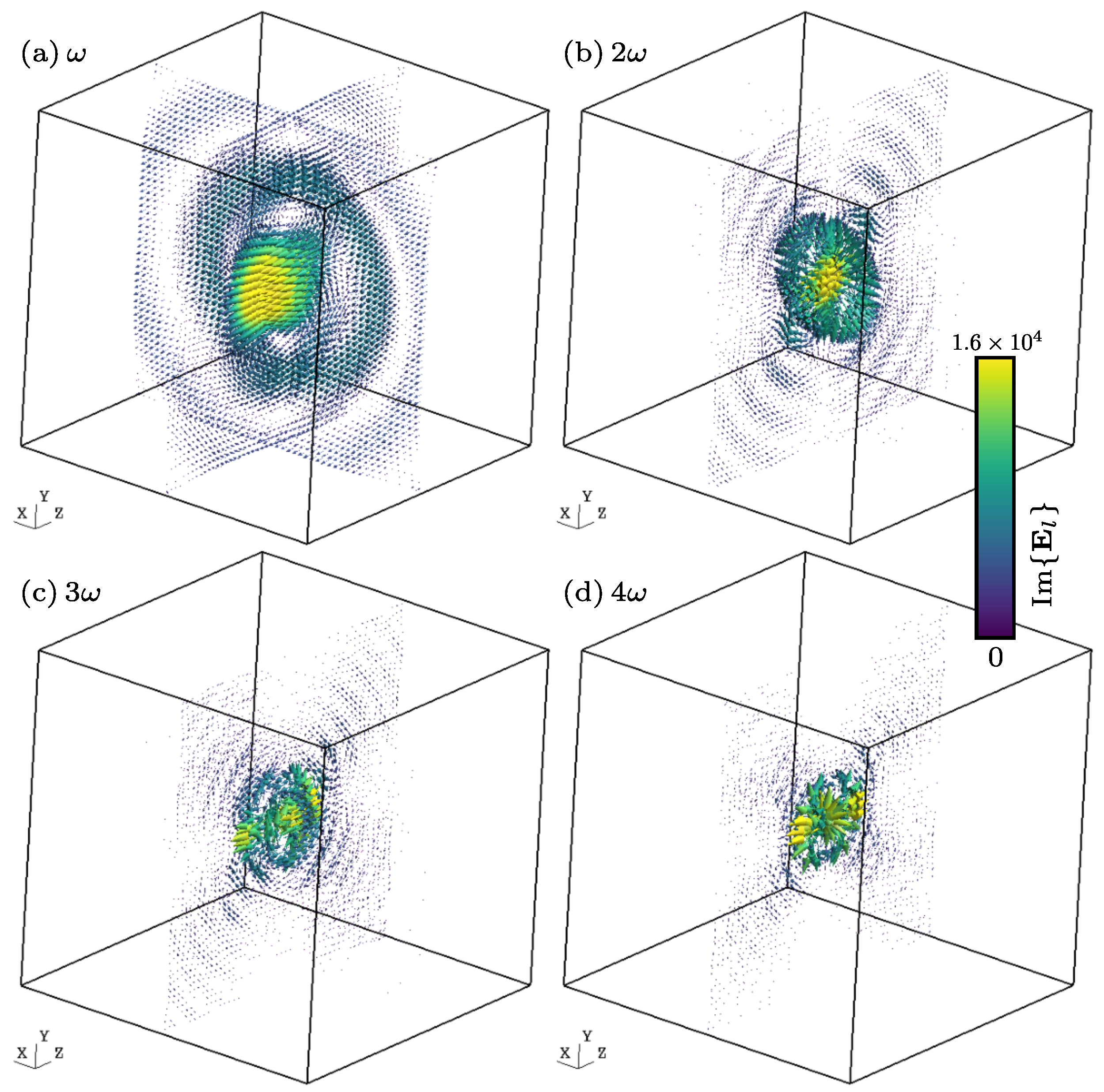
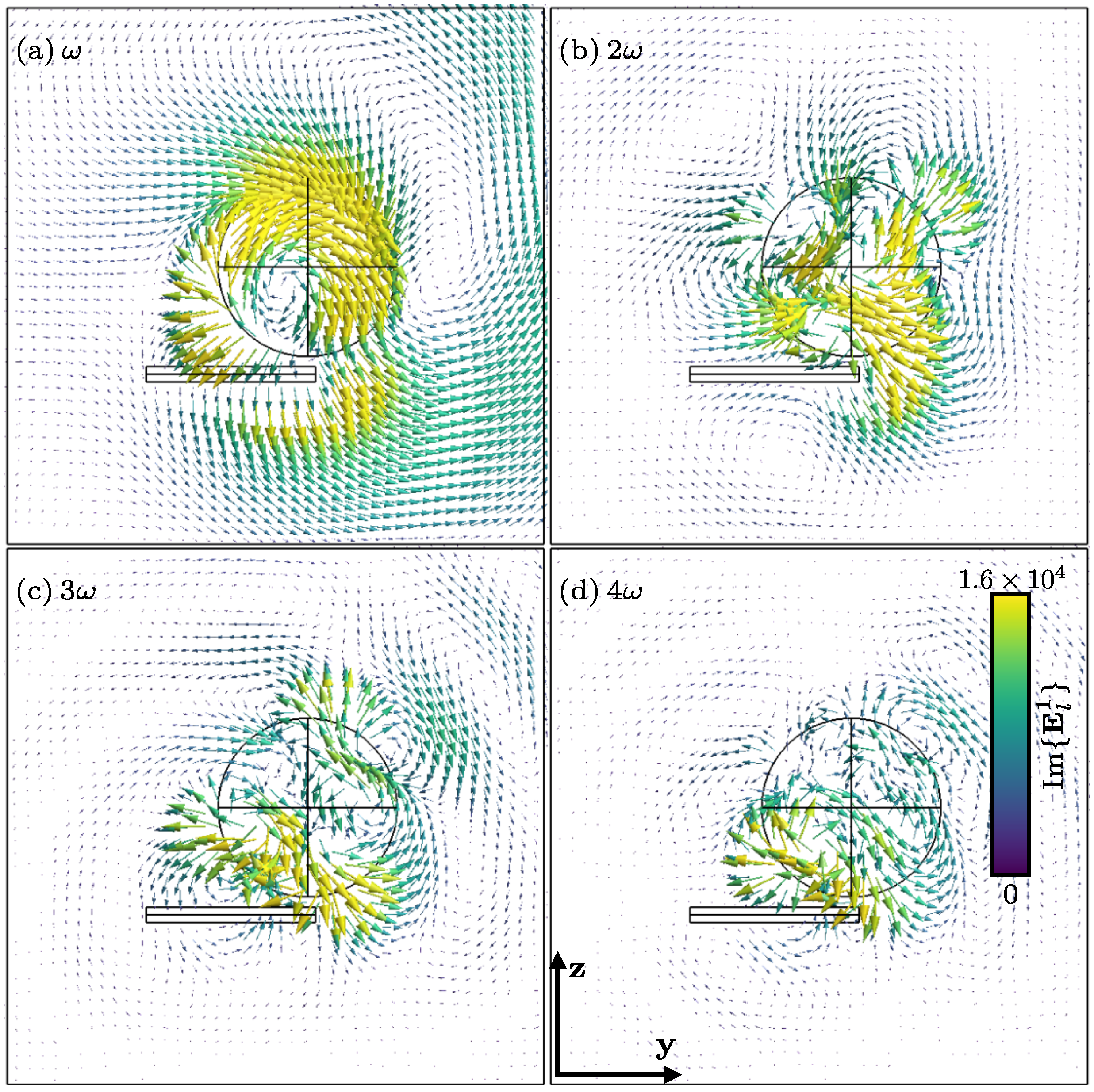
The only drawback we have encountered is that might be singular between and . Figure 1 shows cuts along the planes and of the imaginary part of the harmonic electric field components for . For (cf. Figure 1a), it is possible to recognize the typical shape of the Green function (or point dipole along z). The real part of the harmonic magnetic field components is shown in Figure 2, which, as expected, circles around the z-axis. Finally, the projection of the Poynting vector field on the canonical planes is shown in Figure 3. Again, it is possible to recognize the radiation pattern of the point dipole in Figure 3a. The computation of the electric and magnetic fields has been carried out by means of Equations (52) and (53). In order to compute these integrals numerically, the following change of variables is used: . This allows the term , which comes from the definition of (see (A3)), to be eliminated. With this change of variable, the formulae were coded into GetDP by P. Dular and C. Geuzaine (Liege, Belgium) open-source software [30], from the source available at https://gitlab.onelab.info/getdp/getdp/-/tree/oscillating_multiharm (accessed on 9 November 2014), using a simple trapezoidal rule with 300 integration points. Visualization was then performed using Gmsh v4.12.1 open-source software [31].
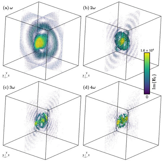
Figure 1.
Harmonic components of the imaginary part of the electric field (in V/m) generated by an oscillating particle, for l = (cuts along the planes and ). The size of the arrows is redundant with the colorscale.
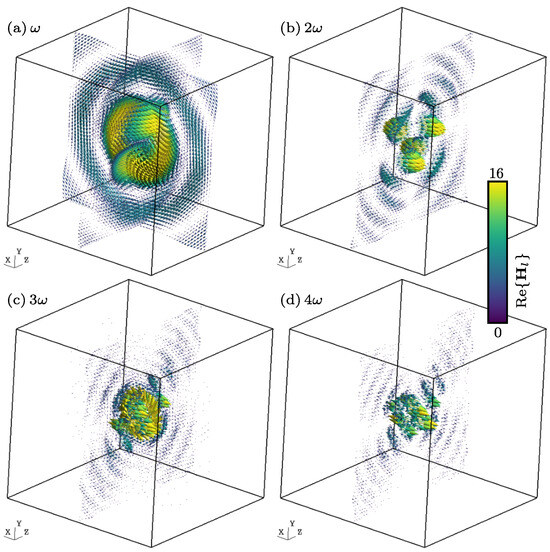
Figure 2.
Harmonic components of the real part of the magnetic field (in A/m) generated by an oscillating particle, for l = (cuts along the planes and ).
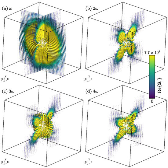
Figure 3.
Harmonic components of the real part of the Poynting vector field (in W/m2) generated by an oscillating particle, for l = (cuts along the planes and ).
3. Results
3.1. Far-Field Radiated Power
As was mentioned before, the main approach towards the study of the EM field generated by an oscillating charge requires consideration of the far field approximation. In this subsection, we demonstrate how it is possible, using the polyharmonic expression from the previous subsections, to retrieve the same results reported in the literature [10].
The Polyharmonic Representation of the EM Far Field Approximations
Remembering Equations (20) and (30), the radiated electric and magnetic induction fields are provided by
where . Using the fact that the electric current is defined as , the fields read
and, as before, , , and . Now, in order to compute the radiated fields ad infinitum, we make the following approximations for when :
By plugging these approximations into Equations (54) and (55), we arrive at the expressions
From this last equation, it is clear that we can focus our attention on just . Therefore, the next step is to consider its polyharmonic representation. Remembering the definitions of in Equation (47) and in (56), we know that
with the spatial coefficient defined as
Here, it is important to emphasize that ; thus, the results obtained in this subsection are for . Notice that the integral term resembles a spatial Fourier transform that goes from , with the new variable
Thus,
This Fourier transform can be easily computed using the definition in Equation (48):
Fortunately, the Fourier transform of is provided in Equation (A5), and after using identity (A27) we obtain
which implies that
where we have defined the dipole moment vector . Notice that this last expression is very similar to the one in [10] for the magnetic dipole field in the radiation zone. Calling
we obtain
and its square norm is provided by
where we have used the fact that . This last result is used later in the study of the radiated power.
3.2. Radiated Power
The expression for the far-field radiated power for an oscillating particle is now derived, first for the relativistic case and later for the non-relativistic one.
- Relativistic case.We know from the definition of the Poynting vector and (57) thatRemembering the Fourier expansion of in Equation (58), we haveNow, we can consider the time-averaged Poynting vector; in light of the fact that is -periodic, we integrate Equation (60) from to to obtainwhere the quantities between the brackets are time-averaged. From the orthogonality of the complex exponential, we haveWhen obtaining the power, it is customary to calculate the flux of the averaged Poynting vector through a spherical surface of radius (while this could be any surface encompassing the EM sources, the spherical surface is the one that allows the simplest calculations), that is,Next, we perform the change of variable:after which the differential readsAfter these calculations, the flux of the averaged Poynting vector readsCallingwhere is the impedance of free space, because we can obtain the averaged energy flux as follows:with as the l-th contribution provided bywhere, by means of the identities obtained in Appendix D, we can see that the integrals are provided bywhere the function is defined trough an integral (see (A37)). Employing Equations (65)–(67), it is possible to compute the radiated power flux in a semi-analytical manner. In particular, if we focus our attention on the case where .or in more explicit fashion,Remark 7.It is important to note that in this case we have made no restrictions regarding the velocity of the charged particle, albeit it cannot be faster than c (this is studied in greater depth in Section 3.3). Thus, the expressions derived here are valid even for charges with speeds near c.
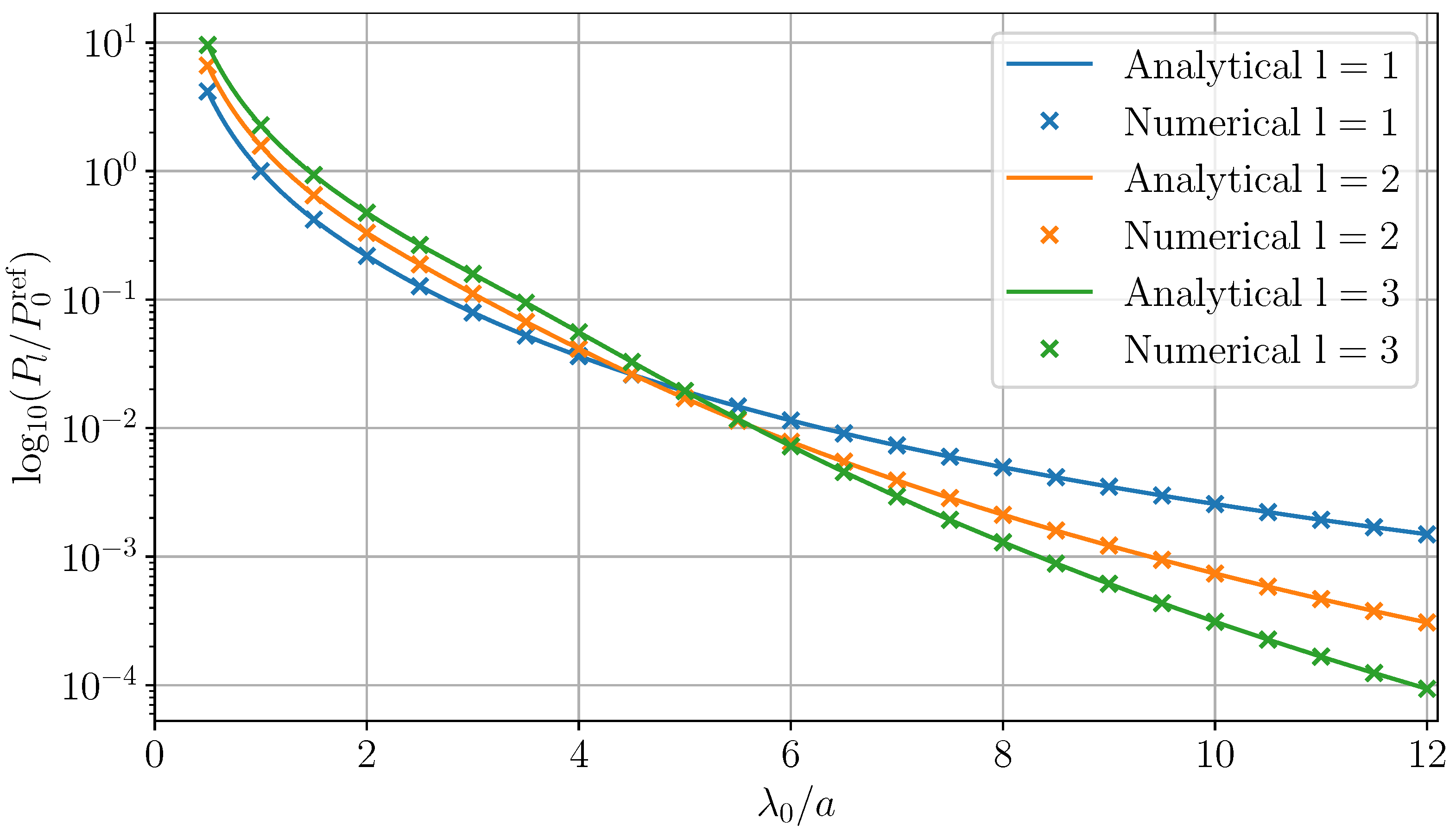
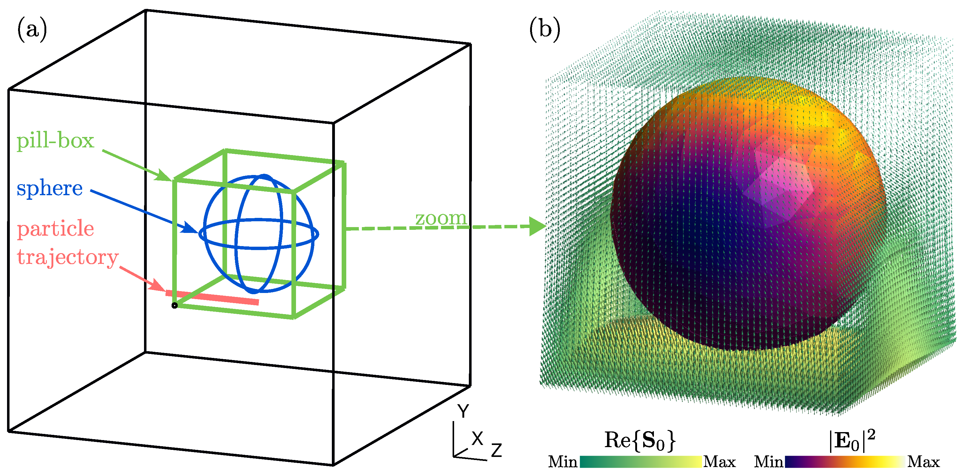
- Non-relativistic case.Let us recall that the position of the charged particle follows the law , which means that the maximum speed attainable by this particle is . In the context of the non-relativistic regime, this necessitates that , or equivalently, . For , we have . In this case, the behaviour of near the origin is well known, namely, ; as a result, we haveand obtaini.e.,The reader may recognize this last equality as the expression used in [10] for the total radiated power. Finally, Figure 4 shows a comparison between the power (for ) obtained analytically by means of (64) when using the far field approximation and the power computed numerically by considering the Poynting vector flux across the surface of a pill box that encloses the trajectory of the charged particle, as depicted in Figure 5b. The Poynting vector is obtained via Equations (52) and (53), and the numerical integrations were performed using the GetDP solver [30]. As can be seen, both approaches fit perfectly.
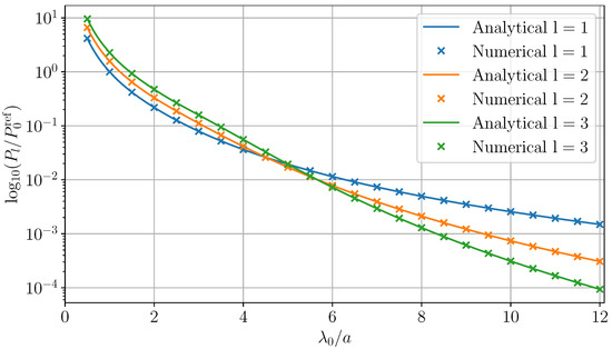 Figure 4. Comparison of the powers () obtained analytically (thick lines) and numerically (crosses), normalized by the quantity obtained analytically for and . The analytical data were obtained by numerical integration of the formula in Equation (64). The numerical data were obtained by 3D numerical intgration of the Poynting vector shown in Figure 3.
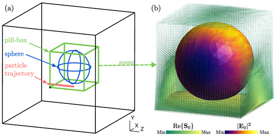 Figure 5. (a) Pill-box surface (green lines) enclosing the sphere (blue lines) on which is plotted the Poynting vector. The trajectory of the particle is indicated by the red line. (b) Zoom on the pill-box and sphere. The yellow–green map represents the real part of the total Poynting vector for . The blue–yellow map represents the square norm of the total electric field for .
3.3. The Particle Cannot Be Supraluminal
It is common sense that for the l-th component of the magnetic induction field in Equation (58) (namely, ) the l-th averaged Poynting vector (see Equation (57)), and the power (provided by Equations (61)–(64)), the value converges with growing l. A divergence would result in a total value of infinity. Due to the connection between , and , it follows that if the magnetic field diverges, then the two others diverge as well.
The magnetic field depends on l only in
For large l, can be written as follows [32]:
Combining this result with Equation (59), it is possible to see that behaves as
This only converges with if the argument of the exponential function is negative, which, in the form of Equation (69), leads to the following inequalities.
With being the maximum velocity of our point charge in this sinusoidal movement, the condition for convergence is matched in the physical sense of Einstein’s postulate that nothing is faster than light [10,11].
Remark 8.
This result holds irrespective of whether the particle has a mass.
3.4. Multipolar Expansion of the Fields
The results presented in the preceding subsection indicate that the radiated power calculated using the polyharmonic representation of the EM field aligns with the results derived from the oscillating point dipole approximation, when the far field approximation is used. This subsection aims to elucidate the reasons behind this phenomenon and to provide a method for estimating the error associated with this approximation. In order to illustrate this method, we examine the Coulomb field outlined in Equation (28), applying the polyharmonic representation of the charge density () as defined in Equations (44) and (49), that is,
To simplify our analysis, it is convenient to define the following function:
where . Upon substitution of Equation (71) into Equation (70), we obtain
The reader can identify the Type 1 integral as defined in Appendix F; however, our analysis requires summing only for . To facilitate this, we note the following relationships:
where the overline symbol denotes the complex conjugate. Consequently, Equation (72) can be reformulated to incorporate these observations, as follows:
The integrals presented in Equation (73) can be reformulated using a vector Taylor series (multipole expansion), as outlined in Equation (A58):
where N represents the highest term in the Taylor expansion and is defined as follows.
Equation (74) establishes a selection rule that links the l-th multiple of the angular frequency with the n-th term of the Taylor expansion (-pole). This relationship is more clearly demonstrated in Table 1, where the truncation term is considered with .

Table 1.
Compatible pairs of l and n, indicated by • symbol, when .
This table exemplifies a broader principle.
Remark 9.
When employing multipole expansion to represent the electromagnetic field generated by an oscillating charge, it becomes apparent that the -pole order of our expansion limits the observable oscillating frequencies . These angular frequencies must adhere to the rule requiring that and be even.
Therefore, the Coulomb field reads
Our next objective is to conduct a similar analysis, this time focusing on the radiated field as described in Equation (30). For this purpose, we use the polyharmonic representation of the current density, , as detailed in Equations (45), (47) and (48). The expression for the radiated field is provided by
By defining the function
we can reformulate Equation (76) as
To ensure that the summation includes only terms with , we observe the following relationships:
With these relationships in mind, Equation (78) can be rewritten as
By considering Equation (A62), we can reformulate Equation (79) as follows:
Here, and follow the same rule established in Equation (74). After conducting elementary manipulations, Equation (80) can be further simplified to
The methodology applied to the field can be similarly employed for the , , and fields. This is achieved by considering the following functions:
By adopting these formulations, we achieve a more lucid representation of the electromagnetic field generated by an oscillating charge. This approach enhances our understanding of the field’s representation as derived in this work as well as of the multipole expansion method. In the following subsection, we demonstrate how the point dipole approximation is inherently encompassed within our more general expression.
Retrieving the Oscillating Point Dipole: Taking
Our aim here is to derive the classical time-dependent point dipole expressions found in standard texts such as [33], specifically under the context of harmonic motion. Additionally, we provide expressions of the truncation error for both the electric and magnetic fields. To illustrate our approach, let us start with the electric field as described in Equation (75), focusing on the case where the truncation term N is set to 1. This choice simplifies our analysis and allows us to directly compare our results with the established point dipole model.
For this last equality, we have applied the selection rule as outlined in Equation (74), particularly focusing on its specific cases where and . Remembering that is defined in Equation (71), we have
where
is the truncation error. Next, we apply the differential operator , as defined in Equation (A45):
with . Substituting this result into Equation (85), after some elementary manipulations we obtain
where . For the field, considering a truncation with , Equation (81) simplifies to
It is important to note that the double sums in Equation (81) vanish due to our choice to set . Recalling the definition of in Equation (77), we obtain
where
Applying the same methodology to the , , and fields and setting the truncation term to leads us to derive the following concise representations of these fields:
with the corresponding truncation errors:
Synthesizing our findings, we can express the electric and magnetic fields with truncation term set to as follows:
and
The expressions derived here may be familiar to the reader as those corresponding to a point oscillating dipole [10,33]; however, it is important to note the inclusion of an additional term representing the Coulomb field of a static point charge located at the origin. This inclusion aligns with our expectations, considering that the zeroth order in the Taylor expansion of is , a component already encompassed within our polyharmonic representation of the electromagnetic field. Furthermore, our approach allows us to articulate the truncation error associated with the point oscillating dipole approximation. This highlights the comprehensive nature of the polyharmonic representation of electromagnetic fields developed in this work.
3.5. Obtaining the Diffracted Field
After all this work, we find that the fields and of the system of Equations (1)–(4) can be regarded as a superposition of waves in the form of Equations (52) and (53). Even more, the analysis of the radiated energy from the previous subsection shows that it is possible to retrieve the classical results from our expressions of and when the non-relativistic far field approximations are considered. The second part of this work, which is going to be considerably shorter that the first part, can be tackled in straightforward fashion. First, the sources in Equation (9) can be easily retrieved by noting that
It is important to notice that is the complex conjugate of the Fourier transform of ; thus,
It is then natural to propose the following as solutions of the system (1)–(4):
Plugging these solutions into Equations (5)–(8) and recalling that , we arrive at the following system which must be satisfied for each :
Taking the curl on Faraday’s Law, we obtain
where the right-hand side of this expression is a source term. Moreover, the equation can be solved, for instance, using the Finite Element Method, as explained in [34,35].
3.6. Numerical Illustration
In order to illustrate the above discussion, we present the following numerical results for the case of an oscillating charged particle close to a sphere (this method can be readily applied to more complicated geometries, as finite elements are used). For the purposes of this example, we consider that the particle oscillates at an angular frequency with nm. The particle oscillates between points of the coordinates and with . The radius of the sphere is and its center is located at . The relative permittivity of the sphere is set to 9 + i. It is important to note that for the sake of simplicity we have used a non-dispersive sphere here; however, it would have been simple to consider temporal dispersion with the proposed method. Finally, all geometries and conformal meshes were obtained using Gmsh software [31], and all finite element formulations in this article were implemented thanks to the flexibility of the GetDP finite element software [30]. Perfectly Matched Layers (PMLs) [36] were used to truncate the surrounding free space. The incident field was hard-coded in GetDP as well, as detailed in Section 2.4.
The mesh size (see Figure 6) was set to , which is very fine at and reasonably coarse at . The 3D scattering problem uses high order Webb hierarchical edge elements [14,37,38] with twenty unknowns per tetrahedron (two unknowns per edge, two unknowns per face). The direct problem corresponding to Equation (97) was solved using the MUMPS direct solver [39], which natively interfaces with GetDP. The number of unknowns of the final discrete system in this example is about 1.8 million, which uses 130 Gb of RAM memory for a resolution time of 20 min per harmonic l on a workstation equipped with of Intel Xeon Platinum processors (2.50 GHz) and with a multithreaded version of MUMPS v5.5.1 running on 32 threads.
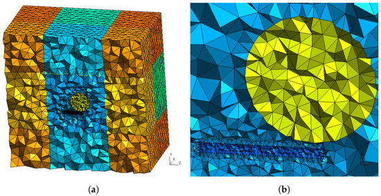
Figure 6.
(a) Mesh showing the different regions of integration and (b) zoom enclosing the sphere and the region where the particle oscillates.
Figure 7 shows the harmonic components of the diffracted field for . Notice that this field was obtained as a numerical solution of (97) using FEM. Moreover, due to the fact that the support of the source term on the right-hand side of Equation (97) is within the sphere, the possible singularity of does not affect our numerical results.
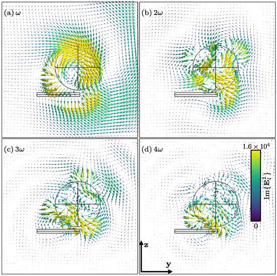
Figure 7.
Harmonic components of the imaginary part of the diffracted electric field (in V/m) for l = (cut in the plane ). For clarity, data in close vicinity to the particle trajectory (elongated rectangle below the sphere) are not displayed.
Figure 8 shows the total electric field () and its interaction with the sphere, whereas the total Poynting vector has been computed as and can be seen in Figure 9 for . It is important in the case of the Poynting vector to see how this is somewhat pulled by the sphere. This is due to the passivity of the material; remember that the permittivity of the sphere is 9 + i.
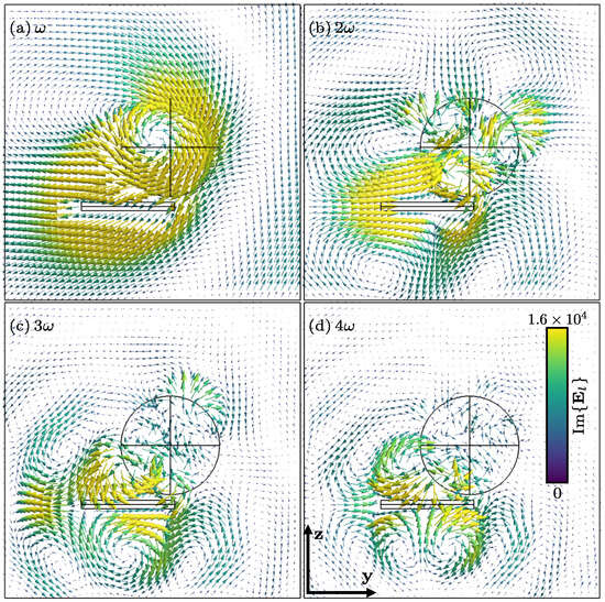
Figure 8.
Harmonic components of the imaginary part of the total electric field (in V/m) for l = (cut in the plane ). for clarity, data in close vicinity to the particle trajectory (elongated rectangle below the sphere) are not displayed.
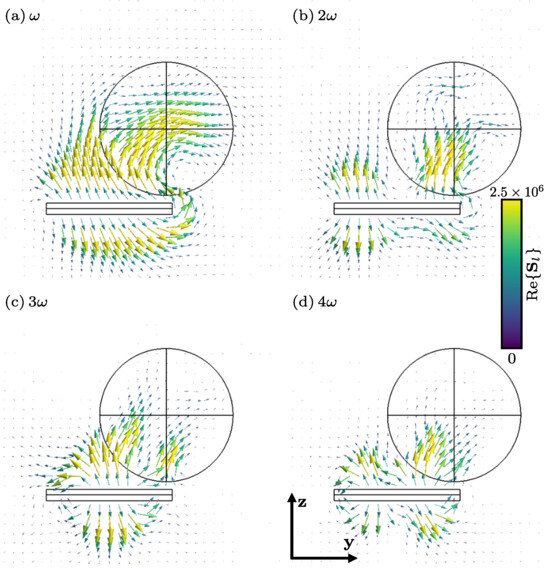
Figure 9.
Harmonic components of the real part of the total Poynting vector field (in W/m2) for l = (cut in the plane ). For clarity, data in close vicinity to the particle trajectory (elongated rectangle below the sphere) are not displayed.
Finally, all of our results have been corroborated by considering an energy balance that measures the total energy flux that crosses a pill-box that surrounds the sphere. This is shown in Figure 5.
4. Conclusions
In this study, the electromagnetic field generated by an oscillating point charge has been thoroughly examined. We have explored and analyzed the methodologies of Liénard-Wiechert, Landau, and Raimond, discussing their respective merits and limitations. Our proposed Fourier representation of the sources has led to the development of a polyharmonic framework for constructing electromagnetic (EM) fields. This approach offers an analytical and practical representation of the EM fields, effectively circumventing the complexities inherent in the previously discussed methods.
Our polyharmonic technique is applicable to both relativistic and non-relativistic scenarios, yielding more comprehensive formulas for the radiated power. Under specific simplifying conditions, these formulas align with the well-known far-field time-dependent dipole radiation power equations frequently referenced in the literature. Furthermore, our multipolar decomposition demonstrates that our solution includes both the Coulomb field and the oscillating point dipole fields, which are typically employed to represent the EM field of an oscillating charge. We elucidate why such approximations fail to capture the more intricate polyharmonic fields with angular frequencies.
The polyharmonic representation is particularly advantageous for studying the interaction between a stiff oscillating charge and a dispersive bulk in the time domain. To illustrate this, we have chosen to focus on a dispersive nanosphere, employing the Finite Element Method (FEM) for our numerical solutions. This choice is justified by the flexibility and adaptability of FEM, which accommodates dispersive bulks with more complex geometries. Our results are validated through an energy balance, ensuring their accuracy and reliability.
It is important to note, however, that our approach has certain limitations. For instance, the impact of the diffracted field on the charge trajectory and the Abraham–Lorentz force are not considered in this study. Future work will address these limitations, along with exploring different configurations of materials, oscillation frequencies, and geometries.
Author Contributions
Conceptualization, F.Z. and A.N.; methodology, M.G.-V., G.D. and F.Z.; software, M.G.-V. and G.D.; validation, M.G.-V., G.D. and F.Z.; formal analysis, G.D., F.Z. and A.N.; investigation, M.G.-V.; Resources, G.D. and F.Z.; data curation, M.G.-V. and G.D.; writing—original draft preparation M.G.-V.; writing—review and editing, G.D., F.Z. and A.N.; visualization, M.G.-V. and G.D.; supervision, G.D. and F.Z.; project administration, G.D. and F.Z. All authors have read and agreed to the published version of the manuscript.
Funding
This research received no external funding.
Institutional Review Board Statement
Not applicable.
Data Availability Statement
The data and source codes necessary to reproduce the numerical results discussed in this paper are available upon request.
Conflicts of Interest
The authors declare no conflicts of interest.
Abbreviations
The following abbreviations are used in this manuscript:
| EM | Electromagnetic |
| FEM | Finite Element Method |
| PLM’s | Perfectly Matched Layers |
Appendix A
In this appendix, we set the Fourier transform convention (in the classical sense) for this work as follows:
If we want to extend these definitions to a wider family of mathematical objects (e.g., s, unit steps, ramps, sines, cosines, etc.), it is necessary to consider the definition of the Fourier transform in the sense of distributions, as per [40,41,42]:
Accordingly, the inverse Fourier transform is defined as follows:
where the brackets denote integration in the whole real line when dealing with regular distributions and is a Gaussian test function, as explained in [40].
Appendix B
In this appendix, we show how to obtain the polyharmonic representation of the sources. For this, the distribution has to be considered as a -distribution of a function . Using the expansion provided in [10,29], we obtain
where are the zeros of the function , i.e.,
In light of the fact that the absolute value of the cosine is bounded by 1, there are only two solutions within the range . Then, by considering the principal branch of the arc cosine function and denoting , these zeros are
In addition, it turns out that for every ( or ) we have , and the -distribution reads
where and is a characteristic function. These last two series of distributions (Dirac’s combs) are expandable in a Fourier series, as follows [41]:
with . Making the change of variables , we obtain
After multiplying this equation by , taking the integral from to , and performing the change of variables , Equation (A2) can be rewritten as
or in a more illuminating way, as
which implies that
Then,
and naturally (recovering the l index),
Remembering the definition of , we obtain
where represents the Chebyshev polynomials of the first kind; therefore,
After plugging this equation into Equation (A1) and defining the function
the function reads
As a consequence of this, the function ȷ is provided by
In short, and ȷ are in the following form:
with
On the other hand, the Fourier transform can be derived by considering the convention
After a suitable change of variable (), we find that
where the last equality comes from the generating function of the Bessel’s functions [42,43,44]. Taking the Fourier transform of Equation (A4) and keeping in mind that these two Fourier series are equal term-by-term, we arrive at this beautiful and unexpected expression:
which is used in Section 3.1.
Appendix C
This appendix is devoted to the deduction of the Liénard-Wiechert fields. In order to fix the main ideas, we are going to deal only with in Equation (33). At first sight, it would be tempting to simply evaluate everything at ; however, it is important to remember that and are functions of the retarded time , which is defined as
Thus, a change of strategy is necessary. Instead of asking, as in Equation (33), which makes for each , we ask which satisfies the transcendental Equation (A6) for each t, the present time, and the given trajectory [21]. Mathematically, the space integral in (33) is equivalent to
The next step in evaluating this integral is to perform a change of variable with respect to the argument of the delta distribution:
Then, the differential is provided by
The derivative of with respect to the retarded time can be easily computed by remembering that
Taking the derivative from both sides, we have
which after some elementary manipulation provides us with
By defining , we finally obtain
Thus, the intermediate magnetic induction field is
where, due to the fact that , the retarded time is defined implicitly as in Equation (A7). Mutatis mutandis, this procedure can be repeated for the other fields in Equations (34)–(37); then, the total electric and magnetic induction fields read
Now, it is necessary to compute the derivatives with respect to the present time t. Assuming the convention that the doted quantities denote partial derivation with respect to time t, the following identities will be useful:
From Equations (A10) and (A11), we can solve for
and upon substitution of Equation (A12) into Equations (A10) and (A11) we obtain
From the expression , we can perform derivation with respect to t; after some manipulations, we obtain
In addition, we have
where denotes the particle acceleration. Finally,
Using these identities, we first deal with in Equation (A8):
where we have defined
It is then necessary to calculate the derivative of :
The first derivative in the right-hand side of Equation (A15) is
and the second one is provided by
Plugging Equation (A16) and Equation (A17) into Equation (A15), we obtain
and substituting Equation (A18) into Equation (A13), we obtain the Liénard-Wiechert magnetic field:
For the case of the electric field, we start again by expressing Equation (A9) in terms of Equation (A14):
Then, we consider the second term in the right-hand side of (A20):
and, using ,
Notice that the first term in Equation (A21) cancels with the third term in Equation (A20). Thus, we can focus our attention on the first term of Equation (A20):
Let us work with the first two terms of Equation (A22):
Now, by means of the vector identity [18], letting , and , we have
On the other hand, the third term on Equation (A22) can be written as
Putting Equations (A23) and (A24) into Equation (A22) and then plugging this result and Equation (A21) into Equation (A20), we finally obtain the electric Liénard-Wiechert field:
It can be seen that, along with Equation (A19), these are the same results as were obtained by Griffiths [11] and by Heald and Marion [21].
Appendix D
Here, the goal is to express with the minimum of ad hoc special functions. For this reason, we derive the integrals used in Section 3.1. As we know, Bessel functions of the first kind are non-diverging solutions at the origin of the differential equation [42,43,45]
which satisfy the identities [29,32,42]
Equipped with these tools, our first goal is to compute the integral
In order to do this, we can consider Equation (A26) and divide it over r. After some elementary manipulations, this equation reads
analogously, for we have
Multiplying Equation (A30) by and Equation (A31) by , then taking the difference, we obtain
Next, we take the integral from 0 to A to obtain
then,
Now, by means of the identity in (A27), it is easy to see Equation (A29) as
The last two integrals in the right-hand side of Equation (A33) can be easily obtained via (A32); finally,
The second goal is to compute the integral
Despite its harmless appearence, this integral poses a challenge for integration, lacking a direct analytical expression in terms of Bessel functions, as highlighted in [46]. To address this, we introduce a recursive method that facilitates the effective computation of this integral.
We starting by assuming , taking the product of Equations (A27) and (A28), and integrating this resulting equation from 0 to A to obtain
After performing integration by parts in the right-hand side of this equation, we arrive at the following expression:
Notice that the last integral in the right-hand side of Equation (A36) is provided by (A34). This establishes a two-step recurrence relation between the integrals and as defined in Equation (A35). Next, we obtain an expression for by considering Equation (A30) with ,
Remembering that , we obtain
and after multiplying by , we have
which implies
After integration by parts, we have
This expression can be arranged in a more illuminating way:
Therefore, at the end Equation (A35) depends only on
An analytical expression for this integral is provided in Section 2.1.3 of [46], as follows:
where in this case. Alternatively, this integral can be accurately evaluated numerically using the periodisation method detailed in [47].
Appendix E
This appendix is devoted to obtaining the Taylor expansion of a vector field . We start by componentwise consideration of the Cartesian ,
Assuming that each admits a Taylor expansion and that , we have
where denotes the n-th application of the operator and is the Lagrange remainder [48] provided by
where s is an unknown number in the interval . Substituting Equation (A39) into Equation (A38), we obtain
By defining the vector
with entries
it is possible write Equation (A40) as
Next, we study the vector . We start by taking , meaning that we have
For ,
This last equality suggest that we should define the following differential operators:
Using these definitions, it is easy to see that
For the case of , we can show that
Because we already have the inductive basis and hypothesis, it only remains to perform the inductive step, that is,
Thus, Equation (A42) is rewritten as
In order to obtain a more tractable expression of Equation (A46) from the practical point of view, we can show that
The inductive basis and hypothesis are provided by Equations (A45) and (A47), respectively. Therefore, the only missing piece is the inductive step for , which proceeds as follows:
With this last result, Equation (A46) takes the following form:
Appendix F
This appendix focuses on analyzing integrals of two specific types. The first type, referred to as Type 1, is defined by the integral
while the second type, known as Type 2, is represented by
Considering the condition , the functions and can be expanded using a vector Taylor series, as shown in Equation (A46):
It is important to note that
therefore, Equation (A51) can be rewritten as
where . To analyze the Type 1 integral, we can substitute Equation (A52) into Equation (A49), leading to
All terms not involving the truncation error depend on an integral of the form
Recalling the definition of in Equation (49) and substituting it into Equation (A54), we obtain
This last integral is listed in [29] as
Considering that (and consequently ) is an even number and that is odd, Equation (A54) can be rewritten as
where is provided by
Consequently, the Type 1 integral expressed in Equation (A53) can be reformulated as
For Type 2 integrals, the approach mirrors that of Type 1. We start by considering
This relies on an integral defined as
which can be straightforwardly calculated considering Equations (48), (A54), and (A57):
Therefore, Equation (A59) can be expressed as follows:
This equation, along with Equation (A58), is instrumental in studying the multipolar expansion of the EM fields generated by the oscillating charge.
References
- Harish, A.; Sachidananda, M. Antennas and Wave Propagation; Oxford University Press: New York, NY, USA, 2007. [Google Scholar]
- Huang, Y.; Boyle, K. Antennas: From Theory to Practice; John Wiley & Sons: Sussex, UK, 2008. [Google Scholar]
- Sommerfeld, A. Partial Differential Equations in Physics: Lectures on Theoretical Physics; Number v. 6 in Pure and Applied Mathematics, 1; Sarat Book House: Kolkata, India, 1960. [Google Scholar]
- Markov, G. Antennas; Progress Publishers: Moscow, Russia, 1958. [Google Scholar]
- Chasseriaux, J. Potential set up by a point charge oscillating in magnitude in an inhomogeneous plasma. Plasma Phys. 1972, 14, 763. [Google Scholar] [CrossRef]
- Klimov, V.V.; Ducloy, M.; Letokhov, V.S. Radiative frequency shift and linewidth of an atom dipole in the vicinity of a dielectric microsphere. J. Mod. Opt. 1996, 43, 2251–2267. [Google Scholar] [CrossRef]
- Klimov, V.; Ducloy, M.; Letokhov, V. Spontaneous emission rate and level shift of an atom inside a dielectric microsphere. J. Mod. Opt. 1996, 43, 549–563. [Google Scholar] [CrossRef]
- Lassalle, E.; Devilez, A.; Bonod, N.; Durt, T.; Stout, B. Lamb shift multipolar analysis. J. Opt. Soc. Am. B 2017, 34, 1348–1355. [Google Scholar] [CrossRef]
- Farhi, A.; Bergman, D.J. Electromagnetic eigenstates and the field of an oscillating point electric dipole in a flat-slab composite structure. Phys. Rev. A 2016, 93, 063844. [Google Scholar] [CrossRef]
- Jackson, J.D. Classical Electrodynamics; Wiley: Hoboken, NJ, USA, 1998. [Google Scholar]
- Griffiths, D. Introduction to Electrodynamics; Prentice Hall: Upper Saddle River, NJ, USA, 1999. [Google Scholar]
- Novotny, L.; Hecht, B. Principles of Nano-Optics; Cambridge University Press: Cambridge, UK, 2012. [Google Scholar]
- Raimond, J.M. M1 Théorie Classique des Champs, Notes de Cours; Université Pierre et Marie Curie, Laboratoire Kastler Brossel: Paris, France, 2016; Available online: http://www.lkb.upmc.fr/cqed/wp-content/uploads/sites/14/2016/09/notes-de-cours.pdf (accessed on 8 June 2017).
- Jin, J. The Finite Element Method in Electromagnetics, 3rd ed.; John Wiley & Sons Inc.: Hoboken, NJ, USA, 2014. [Google Scholar]
- Panofsky, W.K.; Phillips, M. Classical Electricity and Magnetism; Courier Corporation: Chelmsford, MA, USA, 2005. [Google Scholar]
- Jefimenko, O. Electricity and Magnetism: An Introduction to the Theory of Electric and Magnetic Fields; Series in Physics; Appleton-Century-Crofts: Norwalk, CT, USA, 1966. [Google Scholar]
- Petit, R. l’Outil Mathématique: Distributions, Convolution, Transformations de Fourier et de Laplace, Fonctions d’Une Variable Complexe, Fonctions Eulériennes; Masson: Paris, France, 1991. [Google Scholar]
- Ruiz, C. Cálculo Vectorial; Prentice Hall Hispanoamericana, S.A.: Mexico City, Mexico, 1995. [Google Scholar]
- Landau, L.; Lifshitz, E. The Classical Theory of Fields; Course of Theoretical Physics; Butterworth-Heinemann: Cambridge, UK, 1975. [Google Scholar]
- Spohn, H. Dynamics of Charged Particles and Their Radiation Field; Cambridge University Press: Cambridge, UK, 2004. [Google Scholar]
- Heald, M.A.; Marion, J.B. Classical Electromagnetic Radiation; Courier Corporation: North Chelmsford, MA, USA, 2012. [Google Scholar]
- Jentschura, U.D. Advanced Classical Electrodynamics: Green Functions, Regularizations, Multipole Decompositions; World Scientific Publishing Company: Singapore, 2017. [Google Scholar]
- Stratton, J. Electromagnetic Theory; International Series in Pure and Applied Physics; McGraw-Hill Book Company, Inc.: New York, NY, USA, 1941. [Google Scholar]
- Kreyszig, E. Introductory Functional Analysis with Applications; Wiley New York: New York, NY, USA, 1989; Volume 1. [Google Scholar]
- Reddy, B.D. Introductory Functional Analysis: With Applications to Boundary Value Problems and Finite Elements; Springer Science & Business Media: New York, NY, USA, 2013; Volume 27. [Google Scholar]
- Saichev, A.I.; Woyczynski, W.A. Distributions in the Physical and Engineering Sciences. Volume I; Springer: Boston, MA, USA, 1997. [Google Scholar]
- Luo, C.; Ibanescu, M.; Johnson, S.G.; Joannopoulos, J. Cerenkov radiation in photonic crystals. Science 2003, 299, 368–371. [Google Scholar] [CrossRef] [PubMed]
- Lin, X.; Easo, S.; Shen, Y.; Chen, H.; Zhang, B.; Joannopoulos, J.D.; Soljačić, M.; Kaminer, I. Controlling Cherenkov angles with resonance transition radiation. Nat. Phys. 2018, 14, 816–821. [Google Scholar] [CrossRef]
- Arfken, G.; Weber, H.; Harris, F. Mathematical Methods for Physicists: A Comprehensive Guide; Elsevier: Cambridge, MA, USA, 2012. [Google Scholar]
- Geuzaine, C.; Dular, P. GetDP Reference Manual: The Documentation for a General Environment for the Treatment of Discrete Problems; Université de Liège: Liège, Belgium, 1997; Available online: http://getdp.info (accessed on 9 November 2014).
- Geuzaine, C.; Remacle, J.F. Gmsh: A three-dimensional finite element mesh generator with built-in pre- and post-processing facilities. Int. J. Numer. Methods Eng. 2009, 79, 1309–1331. [Google Scholar] [CrossRef]
- Abramowitz, M.; Stegun, I.A. Handbook of Mathematical Functions: With Formulas, Graphs, and Mathematical Tables; Courier Corporation: North Chelmsford, MA, USA, 1964; Volume 55. [Google Scholar]
- Zangwill, A. Modern Electrodynamics; Cambridge University Press: Cambridge, UK, 2013. [Google Scholar]
- Zolla, F.; Renversez, G.; Nicolet, A.; Kuhlmey, B.; Guenneau, S.; Felbacq, D.; Argyros, A.; Leon-Saval, S. Foundations of Photonic Crystal Fibres; Imperial College Press: London, UK, 2005. [Google Scholar]
- Demésy, G.; Zolla, F.; Nicolet, A.; Commandré, M. All-purpose finite element formulation for arbitrarily shaped crossed-gratings embedded in a multilayered stack. JOSA A 2010, 27, 878–889. [Google Scholar] [CrossRef] [PubMed]
- Johnson, S.G. Notes on Perfectly Matched Layers (PMLs); Massachusetts Institute of Technology: Cambridge, MA, USA, 2008; Available online: www-math.mit.edu/~stevenj/18.369/spring09/pml.pdf (accessed on 27 June 2017).
- Geuzaine, C.; Meys, B.; Dular, P.; Legros, W. Convergence of high order curl-conforming finite elements [for EM field calculations]. IEEE Trans. Magn. 1999, 35, 1442–1445. [Google Scholar] [CrossRef]
- Webb, J.; Forgahani, B. Hierarchal scalar and vector tetrahedra. IEEE Trans. Magn. 1993, 29, 1495–1498. [Google Scholar] [CrossRef]
- Amestoy, P.; Duff, I.; Guermouche, A.; Koster, J.; L’Excellent, J.Y.; Pralet, S. MUltifrontal Massively Parallel Solver, (MUMPS 4.8.4), Users’ Guide. CERFACS, ENSEEIHT-IRIT, and INRIA. 2008. Available online: http://graal.ens-lyon.fr/MUMPS (accessed on 5 September 2023).
- Howell, K.B. Principles of Fourier Analysis; CRC Press: Boca Raton, FL, USA, 2016. [Google Scholar]
- Osgood, B. Stanford Engineering Everywhere|EE261—The Fourier Transform and Its Applications. Stanford. 2007. Available online: https://see.stanford.edu/Course/EE261 (accessed on 6 January 2017).
- Asmar, N. Partial Differential Equations with Fourier Series and Boundary Value Problems; Pearson Prentice Hall: Upper Saddle River, NJ, USA, 2005. [Google Scholar]
- Gray, A.; Mathews, G.; MacRobert, T. A Treatise on Bessel Functions and Their Applications to Physics; Macmillan and Co., Limited: London, UK, 1952. [Google Scholar]
- Asmar, N.; Jones, G. Applied Complex Analysis with Partial Differential Equations; Prentice Hall: Upper Saddle River, NJ, USA, 2002. [Google Scholar]
- Simmons, G.F. Differential Equations with Applications and Historical Notes; CRC Press: Boca Raton, FL, USA, 2016. [Google Scholar]
- Rosenheinrich, W. Tables of Some Indefinited Integralsof Bessel Functions of Integer Order; Ernst-Abbe-Hochschule Jena University of Aplied Sciences, Department of Basic Sciences: Jena, Germany, 2019; Available online: https://t.ly/nZonL (accessed on 22 December 2023).
- Helluy, P.; Maire, S.; Ravel, P. Intégration numérique d’ordre élevé de fonctions régulières ou singulières sur un intervalle. Comptes Rendus De L’Académie Des Sci.-Ser. I-Math. 1998, 327, 843–848. [Google Scholar] [CrossRef]
- Skiba, Y. Metodos Y Esquemas Numericos: Un Analisis Computacional; UNAM: Mexico City, Mexico, 2005. [Google Scholar]


Disclaimer/Publisher’s Note: The statements, opinions and data contained in all publications are solely those of the individual author(s) and contributor(s) and not of MDPI and/or the editor(s). MDPI and/or the editor(s) disclaim responsibility for any injury to people or property resulting from any ideas, methods, instructions or products referred to in the content. |
© 2024 by the authors. Licensee MDPI, Basel, Switzerland. This article is an open access article distributed under the terms and conditions of the Creative Commons Attribution (CC BY) license (https://creativecommons.org/licenses/by/4.0/).