Abstract
This paper presents a novel mathematical model to determine the minimum cost for the design of reinforced-concrete strap combined footings under biaxial bending, with each column using a genetic algorithm. The pressure is assumed to be linearly distributed along the contact area. This study comprises two steps: firstly, identifying the smallest ground contact area, and secondly, minimizing the cost. The methodology integrates moment, bending shear, and punching shear calculations according to the ACI standard. Some authors present a smaller area (but limited to one or two property lines) and the design considers that the thickness of the footings and beam are equal, and do not show the lower cost of a strap combined footing; generally, the beam has a greater thickness than the footings and therefore the footings would have an unnecessary thickness that would generate a higher cost. A numerical example is shown to find the lowest cost for the design of strap combined footings considering four different conditions such as square footings and other limitation at the ends of the footings. The minimum area does not guarantee that it is the lowest cost. The proposed model is versatile, applicable to T-shaped and rectangular combined footings, and is not restricted to specific property lines. The contributions include eliminating trial and error practices, accommodating various design conditions, and emphasizing equilibrium in the derived equations. The model is adaptable to different building codes, offering a comprehensive approach to achieving optimal design and cost considerations for strap combined footings.
Keywords:
minimum surface; minimum cost; strap combined footings; moments; bending shears; punching shear MSC:
32A40
1. Introduction
The main objective of a foundation is to transfer the loads of columns or walls to the resistant strata of the soil, in such a way ensuring stability and permissible settlements according to site standards.
Foundations generally fall into two categories: shallow and deep.
The choice of shallow foundations may vary depending on the type of soil, the layout, the magnitude and nature of the loads, among other things.
The different types of reinforced concrete footings are: isolated footings, combined footings, strap footings and raft or mat foundations.
The isolated footings can be: square, rectangular or circular. The combined footings can have the following shape: rectangular, trapezoidal, strap, L (corner) and T.
Many mathematicians have explored mathematical models for the optimal design of reinforced concrete foundations.
The models for the smallest contact area with the ground have been developed for circular, square and rectangular isolated footings under biaxial bending [1,2,3,4,5,6,7,8,9,10,11]. Likewise, models have been presented for combined footings for the smallest contact area with the ground under biaxial bending in each column of L-shaped or corner [12], strap [13] and T-shaped [14] footing.
Several models have been developed for the comprehensive design of reinforced concrete for circular, square and rectangular isolated footings subjected to biaxial bending [15,16,17,18,19,20]. Likewise, models for combined footings have been investigated for the complete design of reinforced concrete under biaxial bending in each column of trapezoidal-shaped [21], rectangular [22], L or corner [23], strap [24] and T [25] footing.
Several researchers have studied optimization following the minimum-cost criterion for square or rectangular isolated footings using different algorithms such as the hybrid big bang–big crunch [26], multi-objective genetic [27], global–local gravitational search [28], mixed-integer nonlinear programming [29], binary-coded genetic and unified particle swarm optimization [30], genetic according to ACI [31], generalized reduced gradient method [32] and computational methods [33]. Some researchers have presented optimization based on a practical tool called metaheuristic [34,35], other researchers have taking into account the eccentricity in the footings [36,37,38], including for circular isolated footings subjected to generalized loadings using the sequential unconstrained minimization technique [39]. Other researchers have proposed models for the lowest cost design for rectangular combined footings using the modified complex box method [40], using algorithms based on swarm intelligence [41] and, for trapezoidal combined footings, using nonlinear programming methods [42].
According to the bibliographic review, the documents closest to the topic presented in this work are: Aguilera-Mancilla et al. [13] developed a mathematical model for strap combined footings under biaxial bending in each column for the contact area with the soil, but it is restricted to one or two sides in the longitudinal direction, i.e., the case of free sides is not presented. Yáñez-Palafox et al. [24] presented a mathematical model for strap combined footings under biaxial bending in each column for the complete design (areas of steel and thickness) from the known dimensions of the footing, but it is limited to the thickness of footings and beam being equal, one or two property lines, and does not show the lower-cost design. Therefore, this work is complete because it presents the minimum area for the four possible conditions and for the minimum-cost design it shows the four possible conditions and takes into account different thicknesses for the footings and beam.
This paper presents a new mathematical model to obtain the minimum-cost design for the reinforced concrete strap combined footings under biaxial bending, with each column using a genetic algorithm and the pressure being assumed to be linearly distributed along the contact area. This work was carried out in two steps: step one shows the smallest area in contact with the soil and step two presents the lowest cost. The moments, bending shears and punching shears were obtained by integration according to the ACI standard of the American Concrete Institute (318-14) [43]. A numerical example is shown to find the minimum cost for the design of strap combined footings taking into account four different conditions: (1) when the footing in the Y direction is not restricted at the ends; (2) when the two footings are square and the columns are located in the centers of the footings; (3) when footing 1 is square and column 1 is located in the center of the footing and footing 2 is not restricted at the ends; (4) when footing 2 is square and column 1 is located in the center of the footing and footing 1 is not restricted at the ends.
2. Materials and Methods
The available allowable load capacity of the soil qaa is obtained by the following equation [44]:
where: qa = allowable load capacity of the soil—this must be determined by principles of soil mechanics in accordance with the general building code (kN/m2); γwf = the self-weight of the footing (kN/m2); γws = the self-weight of the soil fill (kN/m2); γcd = concrete density (24 kN/m3); γsd = soil density (kN/m3); d = effective depth of the footing (m); r = the coating of the footing (m); H = the depth of the footing measured from the base of the footing to the ground-free surface (m).
Figure 1 shows a strap combined footing that supports two rectangular columns of different dimensions under an axial load and with two orthogonal moments in each column.
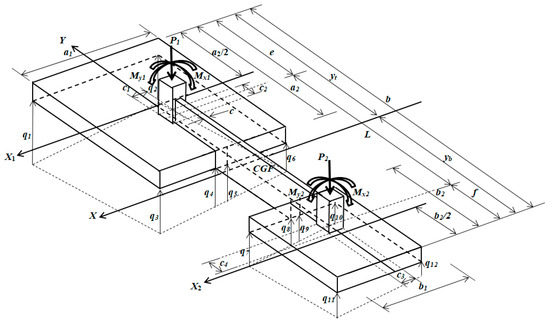
Figure 1.
Isometric view of a strap combined footing.
Table 1 shows the coordinates (x, y) of the pressures below a footing at each vertex with respect to the X and Y axes.

Table 1.
Coordinates (x, y) of the strap combined footing at each vertex.
Table 2 presents the coordinates (x1, y1) of the pressures below footing 1 at each vertex with respect to the X1 and Y1 axes.

Table 2.
Coordinates (x1, y1) of footing 1 at each corner.
Table 3 shows the coordinates (x2, y2) of the pressures below footing 2 at each vertex with respect to the X2 and Y2 axes.

Table 3.
Coordinates (x2, y2) of footing 2 at each corner.
2.1. Minimum Contact Area on the Soil for Strap Combined Footings
The objective function for smallest contact area with the ground “Amin” is [13]:
The constraint functions are:
where: e = the distance from the center of column 1 to the free end of the footing in the Y direction (m), f = the distance from the center of column 2 to the free end of the footing in the Y direction (m), R = resultant force (kN), MxT = resultant moment around the X axis (kN-m), MyT = resultant moment around the Y axis (kN-m), xn = the distance in the X direction measured from the Y axis to the fiber under study (m), yn = the distance in the Y direction measured from the X axis to the fiber under study (m), A = the area of the footing (m2), yt = the distance to the center of gravity of the footing in the positive Y direction (m), yb = the distance to the center of gravity of the footing in the negative Y direction (m), Ix = the moment of inertia with respect to the X axis (m4), Iy = the moment of inertia with respect to the Y axis (m4).
2.2. Minimum-Cost Design for Strap Combined Footings
The moments, bending shears and punching shears that act on the footing are obtained by integration.
The analysis in the Y direction is carried out with all loads and moments, and the analysis in the X direction is carried out individually for each footing, i.e., for footing 1, the X1 axis is considered and, for footing 2, the X2 axis is considered.
The general equation for any footing under biaxial bending using factored loads and moments in the Y direction is [24]:
where: qu = the soil pressure under the footing due to the factored loads and moments, Ru = the factored resultant force (kN), MuxT = the factored resultant moment around the X axis (kN-m), MuyT = the factored resultant moment around the Y axis (kN-m).
The general equation for any footing under biaxial bending using factored loads and moments in the X1 direction on footing 1 is:
where: qu1 = the soil pressure under footing 1 due to the factored loads and moments of column 1, Pu1 = the factored axial load of footing 1 (kN), Mux1 = the factored moment around the X1 axis (kN-m), Muy1 = the factored moment around the Y1 axis (kN-m), A1 = a1a2, Ix1 = a1 a23/12, Iy1 = a13a2/12.
The general equation for any footing under biaxial bending using factored loads and moments in the X2 direction on footing 2 is:
where: qu2 = the soil pressure under footing 2 due to the factored loads and moments of column 2, Pu2 = the factored axial load of footing 2 (kN), Mux2 = the factored moment around the X2 axis (kN-m), Muy2 = the factored moment around the Y2 axis (kN-m), A2 = b1b2, Ix2 = b1 b23/12, Iy2 = b13b2/12.
2.2.1. Moments
Critical sections for moments appear in sections a, b, c, d, e, f, g, h and i, as shown in Figure 2.
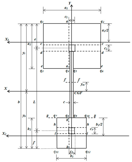
Figure 2.
Critical sections for moments that correspond to the axes a, b, c, d, e, f, g, h and i.
The general equations for each moment on their respective axes are:
For yt − e ≥ ym ≥ yt − a2
For yt − a2 ≥ ym ≥ yt − b + b2
For yt − b + b2 ≥ ym ≥ yt − b + f
where: Mua, Mub, Muc, Mud, Mue, Muf, Mug, Muh and Mui are the factored moments acting on each axis (kN-m); ym is the location of the maximum moment; and Ru, MuxT and MuyT are obtained by Equations (5)–(7) using factored loads and moments.
Note: The moment “Muf” is obtained using Equations (27)–(29) depending on where “ym” is located. The steps to obtain the maximum moment “Muf” are: (1) Equations (27)–(29) are developed and subsequently differentiated with respect to ym and set equal to zero to obtain the position of the maximum moment; (2) the equation that should be used to obtain the maximum moment depends on the location of ym.
2.2.2. Bending Shears
The critical bending shear sections appear in sections j, k, l, m, n, o, p and q, as shown in Figure 3.
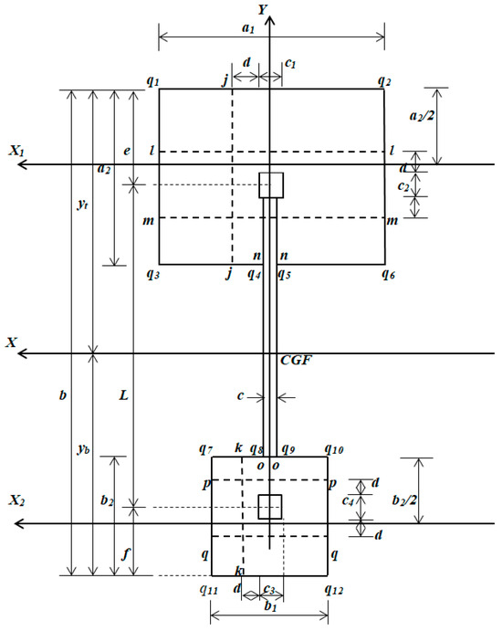
Figure 3.
Critical bending shear sections that correspond to the axes j, k, l, m, n, o, p and q.
The general equations for each bending shear on their respective axes are:
where: Vuj, Vuk, Vul, Vum, Vun, Vuo, Vup and Vuq are the factored bending shears that act on each axis (kN) and d = the effective depth of the footing (m).
2.2.3. Punching Shears
The critical punching shear sections appear at a distance “d/2” starting from the junction of the column with the footing in two directions, as shown in Figure 4.
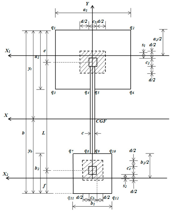
Figure 4.
Critical punching shear sections that correspond to each column.
The general equations for each punching shear that acts on the footing due to each column are:
where: Vup1 and Vup2 are the factored punching shears that act on each column (kN), e ≥ c2/2 + d/2 → s1 = d/2 and e ≤ c2/2 + d/2 → s1 = s1, f ≥ c4/2 + d/2 → s2 = d/2 and f ≤ c4/2 + d/2 → s2 = s2.
2.2.4. Objective Function for Lower Cost
The lowest cost is presented based on the cost of steel and the cost of concrete (the costs include materials and manpower). The lowest cost of the strap combined footing is [38]:
where: Cmin = lower cost (dollars); Cc = the cost of concrete (dollars/m3); Cs = the cost of steel (dollars/kN); Vc = concrete volume (m3); Vs = steel volume (m3); γs = Steel density (76.94 kN/m3).
The volumes for the strap combined footings are:
where: Asyf1B = the steel area at the bottom of footing 1 in the Y direction with a width of a1 (m2); Asyf1T = the steel area at the top of footing 1 in the Y direction with a width of a1 (m2); Asxf1B = the steel area at the bottom of footing 1 in the X direction with a width of a2 (m2); Asxf1T = the steel area at the top of footing 1 in the X direction with a width of a2 (m2); Asyf2B = the steel area at the bottom of footing 2 in the Y direction with a width of b1 (m2); Asyf2T = the steel area at the top of footing 2 in the Y direction with a width of b1 (m2); Asxf2B = the steel area at the bottom of footing 2 in the X direction with a width of b2 (m2); Asxf2T = the steel area at the top of footing 2 in the X direction with a width of b2 (m2); AsbB = the steel area at the bottom of the beam in the Y direction with a width of c (m2); AsbT = the steel area at the top of the beam in the Y direction with a width of c (m2); Asv = the steel area due to beam shear in the transverse direction; d1 = the effective depth of the beam (m); n = the number of stirrups.
Note: Asv is the number of times the steel area of the stirrup crosses the neutral axis of the beam and, in this case, it will be twice the steel area of the stirrup; the length of each stirrup will be 2c + 2d1 − 6r.
By substituting Equations (57) and (58) into Equation (56) we obtained:
Now, substituting γsCs = αCc into Equation (57) is presented:
where: α = γsCs/Cc (the relationship between the cost of steel and the cost of concrete).
2.2.5. Constraint Functions
The moment equations are [43]:
where: Øf = the bending strength reduction factor (0.90); fy = the specified yield strength of the reinforcement of steel (MPa); f’c = the specified compressive strength of the concrete at 28 days (MPa); the width of the study surface for moment bw for Mua is a2, for Mub it is b2, for Muc and Mud it is a1, for Mue, Muf and Mug it is c, for Muh and Mui it is b1; the area of steel for moment As,for Mua is Asxf1B, for Mub it is Asxf2B, for Muc and Mud it is Asyf1B, for Muf it is AsbT, for Mue and Mug it is AsbB, for Muh and Mui it is Asyf2B.
The bending shear equations are [43]:
where: Øv = the shear strength reduction factor (0.85); s = the space between stirrups; the width of the study surface for bending shear bws for Vuj is a2, for Vuk it is b2, for Vul and Vum it is a1, for Vun and Vuo it is c, for Vup and Vuq it is b1.
The punching shear equations are [43]:
where: βc = the long side of the column divided by the short side of the column; b0 = the critical punching shear perimeter (m); αs = 30 for edge columns, αs = 20 for corner columns, and αs = 40 for interior columns.
The percentages of reinforcing steel are [43]:
The reinforcing steel areas are [43]:
where: Asxf1T, Asyf1T, Asxf2T and Asyf2T = the steel areas by temperature, these areas of steel are provided when the thickness is greater than 30 cm and there is no bending [43].
Figure 5 presents the algorithm for the optimal design process of strap combined footings (flowchart).
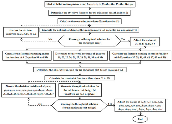
Figure 5.
Process for the optimal design of reinforced concrete strap combined footings.
Figure 6 shows the use of software (Maple 15) for the optimal design of strap combined footings (flowchart).
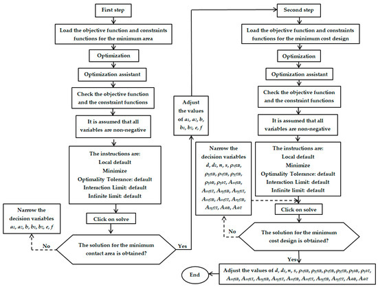
Figure 6.
Process of using software (Maple 15) for the optimal design of reinforced concrete strap combined footings.
3. Numerical Examples
Table 4 and Table 5 show the four examples of obtaining optimal designs for the reinforced concrete strap combined footings under biaxial bending (one axial load and two orthogonal moments in each column). Example 1: When the footing in the Y direction is not restricted at the ends. Example 2: When the two footings are square, and the columns are located in the center of the footings. Example 3: When footing 1 is square and column 1 is located in the center of the footing, and footing 2 is not restricted at the ends. Example 4: When footing 2 is square and column 1 is located in the center of the footing, and footing 1 is not restricted at the ends.

Table 4.
Minimum area of strap combined footings.

Table 5.
Minimum-cost design for strap combined footings.
The general data for the footings of the four examples are: c1 = c2 = c3 = c4 = c = 0.40 m, r = 0.08 m, L = 7.00 m, H = 2.50 m, PD1 = 800 kN, PL1 = 500 kN, MDx1 = 200 kN-m, MLx1 = 150 kN-m, MDy1 = 140 kN-m, MLy1 = 100 kN-m, PD2 = 600 kN, PL2 = 400 kN, MDx2 = 150 kN-m, MLx2 = 100 kN-m, MDy2 = 140 kN-m, MLy2 = 100 kN-m, qa = 260 kN/m2, γcd = 24 kN/m3, γsd = 15 kN/m3, f’c = 28 MPa, fy = 420 MPa and α = 90.
The final total thickness of the footing after making several iterations is 1.10 m. Now, substituting the corresponding values into Equation (2) gives: qaa = 212.60 kN/m2. The unfactored loads and moments acting on the ground are: P1 = 1300 kN, Mx1 = 350 kN-m, My1 = 240 kN-m, P2 = 1000 kN, Mx2 = 250 kN-m and My2 = 240 kN-m. The factored loads and moments acting on the ground are: Pu1 = 1760 kN, Mux1 = 480 kN-m, Muy1 = 328 kN-m, Pu2 = 1360 kN, Mux2 = 340 kN-m and Muy2 = 328 kN-m.
4. Results
The verification process is carried out by substituting in the known points for moments and bending shears, and for the punching shears they are compared with the equations proposed by Yañez-Palafox [24].
The verification of the proposed model is presented below.
- For moments:
- If c1/2 is replaced by a1/2 in Equation (17) to find the moment about the axis formed by q1 and q3, the moment Mq1q3 = 0.
- If c1/2 is replaced by −a1/2 and the addition of Pu1 a1/2 + Muy1 into Equation (17) to obtain the moment about the axis formed by q2 and q6, the moment Mq2q6 = 0.
- If c3/2 is replaced by b1/2 in Equation (19) to find the moment about the axis formed by q7 and q11, the moment Mq7q11 = 0.
- If c3/2 is replaced by −b1/2 and the addition of Pu2b1/2 + Muy2 into Equation (19) to obtain the moment about the axis formed by q10 and q12, the moment Mq10q12 = 0.
- If c2/2 and e are eliminated from Equation (21) to obtain the moment about the axis formed by q1 and q2, the moment Mq1q2 = 0.
- If c4/2 and f are eliminated in the integrals and replaced by Pu2f and Pu2c4/2 in Equation (34) to find the moment about the axis formed by q11 and q12, the moment Mq11q12 = 0.
- For bending shears:
- If c1/2 + d is replaced by a1/2 in Equation (36) to find the bending shear about the axis formed by q1 and q3, the bending shear Vq1q3 = 0.
- If c1/2 + d is replaced by −a1/2 and the addition of −Pu1 into Equation (36) to find the bending shear about the axis formed by q2 and q6, the bending shear Vq2q6 = 0.
- If c3/2 + d is replaced by b1/2 in Equation (38) to find the bending shear about the axis formed by q7 and q11, the bending shear Vq7q11 = 0.
- If c3/2 + d is replaced by −b1/2 and the addition of −Pu2 into Equation (38) to find the bending shear about the axis formed by q10 and q12, the bending shear Vq10q12 = 0.
- If e, c2/2 and d are eliminated from Equation (40) to obtain the bending shear about the axis formed by q1 and q2, the bending shear Vq1q2 = 0.
- If c4/2, d and f are eliminated from Equation (50) to obtain the bending shear about the axis formed by q11 and q12, the bending shear Vq11q12 = 0.
- For moments and bending shears:
- If Equations (27)–(29) are developed and differentiated with respect to ym and set equal to zero, the position of the maximum moment is obtained. Now, if yt − e − c2/2 − d is replaced by ym in Equation (42), yt − b − b2 is replaced by ym in Equation (46) and yt − b + f + c4/2 + d is replaced by ym in Equation (48) and the equations are developed and set equal to zero, the position of the maximum moment is obtained. The positions of the maximum moment ym through the moment and bending shear equations are the same.
- For punching shears:
- If s1 = 0 and e = c2/2 are substituted into Equation (53), the punching shear Vup1 is obtained with footing 1 limited in the Y direction. This equation is presented in equation (63) by Yañez-Palafox [24].
- If b = c2/2 + L + b2/2, s2 = d/2 and f = b2/2 are substituted into Equation (55), the punching shear Vup2 is obtained with footing 1 limited in the Y direction and footing 2 is square and column 2 is located in the center of the footing. This equation is presented in equation (65) by Yañez-Palafox [24].
Table 4 (the minimum area for strap combined footings) shows the following: When the sides of the two footings are not limited in the Y direction (Example 1), the smallest area is presented.
Table 5 (the minimum-cost design for strap combined footings) presents the following: When one side of the two footings is not located on the face of the column in the Y direction and the footings are square (Example 2), the lowest cost occurs.
Figure 7 shows in detail the dimensions and area of reinforcing steel for a strap combined footing.
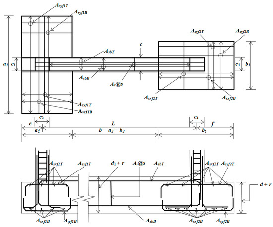
Figure 7.
Diagram of a reinforced concrete strap combined footing.
5. Conclusions
This paper presents an analytical model to determine the minimum cost for the design of strap combined footings under biaxial bending due to the force exerted by each column; the footings are supported on elastic soil, and the analysis assumes a linear distribution of soil pressure.
This work is presented in two steps. Step one is to find the minimum area; the independent variables are: L, c, c1, c2, c3, c4, P1, Mx1, My1, P2, Mx2, My2 and qaa, and the dependent variables are: Amin, a1, a2, b, b1, b2, e and f. Once the dimensions of the footing are known, the work continues with step two. Step two is to obtain the minimum cost; the independent variables are: a1, a2, b, b1, b2, c, c1, c2, c3, c4, e, f, Pu1, Mux1, Muy1, MuxT, Pu2, Mux2, Muy2, MuyT, Ru and Asv, and the dependent variables or decision variables are: Cmin, d, d1, n, s, ρxf1B, ρyf1B, ρxf2B, ρyf2B, ρybB, ρybT, Asxf1B, Asxf1T, Asyf1B, Asxf2B, Asxf2T, Asyf1T, Asyf2B, Asyf2T, AsbB and AsbT.
The main contributions are:
- Some engineers use trial and error to find the dimensions of strap combined footings under biaxial bending, and the design is obtained by assuming maximum and uniform pressure along the bottom of the footing.
- The proposed model is not limited to d = d1 or to one or two property lines, as presented by some authors [13,24].
- The equations for the moments, bending shears and punching shears are verified by equilibrium (see Section 4).
- The minimum area does not guarantee that it is the lowest cost, since the smallest area is presented in example 1 and the lowest cost appears in example 2.
- The proposed model in this paper can be used for any other building code, taking into account the equations that resist the moments, the bending shears and the punching shears, and the equations to obtain the steel areas of the footings and beams.
- This model can be used for T-shaped combined footings by substituting c with b1 and b2 with b − a2 in all equations.
- This model can be used for rectangular combined footings by substituting c with a1, b1 with a1, b2 with b and a2 with b in all equations.
Future papers may be the minimum-cost design for a strap combined footings under biaxial bending, assuming that the contact area of the footing with the ground works partially in compression (one part of the footing contact area is under compression and the other part has no pressure or zero pressure).
Author Contributions
A.L.-R. contributed to the original idea of the article, the mathematical development of the new model and coordinated the work in general. V.M.M.-L. contributed to the verification of the model and the discussion of results. G.S.-H. contributed to the programming of the MAPLE 15 software. F.J.O.-C. contributed to the verification of the new model. L.D.L.-L. contributed to the application of the proposed model (examples). E.R.D.-G. contributed to the elaboration of the bibliographic review, figures and tables. All authors have read and agreed to the published version of the manuscript.
Funding
The research described in this work was funded by the Universidad Autónoma de Coahuila and Universidad Autónoma del Estado de Hidalgo, Mexico.
Data Availability Statement
No new data were created or analyzed in this study. Data sharing is not applicable to this article.
Acknowledgments
The research described in this work was developed at the Universidad Autónoma de Coahuila and Universidad Autónoma del Estado de Hidalgo, Mexico.
Conflicts of Interest
The authors declare no conflicts of interest.
References
- Girgin, K. Simplified formulations for the determination of rotational spring constants in rigid spread footings resting on tensionless soil. JCEM 2017, 23, 464–474. [Google Scholar] [CrossRef]
- Basudhar, P.K.; Das, A.; Das, S.K.; Dey, A.; Deb, K.; De, S. Optimal cost design of rigid raft foundation. In Proceedings of the 10th East Asia-Pacific Conference on Structural Engineering and Construction (EASEC-10), Bangkok, Thailand, 3–5 August 2006; pp. 39–44. [Google Scholar]
- Algin, H.M. Stresses from linearly distributed pressures over rectangular areas. Int. J. Numer. Anal. Methods Geomech. 2000, 24, 681–692. [Google Scholar] [CrossRef]
- Algin, H.M. Practical formula for dimensioning a rectangular footing. Eng. Struct. 2007, 29, 1128–1134. [Google Scholar] [CrossRef]
- Aydogdu, I. New Iterative method to Calculate Base Stress of Footings under Biaxial Bending. Int. J. Eng. Appl. Sci. 2016, 8, 40–48. [Google Scholar] [CrossRef][Green Version]
- Highter, W.H.; Anders, J.C. Dimensioning Footings Subjected to Eccentric Loads. J. Geotech. Eng. 1985, 111, 659–665. [Google Scholar] [CrossRef]
- Vitone, D.M.A.; Valsangkar, A.J. Stresses from Loads over Rectangular Areas. J. Geotech. Eng. 1986, 112, 961–964. [Google Scholar] [CrossRef]
- Özmen, G. Determination of Base Stresses in Rectangular Footings under Biaxial Bending. Tek. Dergi Digest. 2011, 22, 1519–1535. [Google Scholar]
- Dagdeviren, U. Shear stresses below the rectangular foundations subjected to biaxial bending. Geomech. Eng. 2016, 10, 189–205. [Google Scholar] [CrossRef]
- Keskin, M.S.; Bildik, S.; Laman, M. Experimental and Numerical Studies of Vertical Stresses Beneath the Circular Footings on Sand. Appl. Sci. 2023, 13, 1635. [Google Scholar] [CrossRef]
- Shaaban, M.Q.; Al-kuaity, S.A.; Aliakbar, M.R.M. Simple function to find base pressure under triangular and trapezoidal footing with two eccentric loads. Open Eng. 2023, 13, 20220458. [Google Scholar] [CrossRef]
- Naik, B.; Sandeep Nighojkar, S.; Pendharkar, D.U. Effectiveness of Skirt in Rectangular Combined Footing for Two Symmetric Columns. IOSR-JMCE 2020, 17, 11–23. [Google Scholar]
- Aguilera-Mancilla, G.; Luévanos-Rojas, A.; López-Chavarría, S.; Medina-Elizondo, M. Modeling for the strap combined footings Part I: Optimal dimensioning. Steel Compos. Struct. 2019, 30, 97–108. [Google Scholar] [CrossRef]
- Luévanos-Rojas, A.; López-Chavarría, S.; Medina-Elizondo, M. A new model for T-shaped combined footings Part I: Optimal dimensioning. Geomech. Eng. 2018, 14, 51–60. [Google Scholar] [CrossRef]
- Babu, T.S.; Ibrahim, S.K.N. Design of circular footings considering soil-structure interaction. In Proceedings of the International Conference on Smart Materials and Structures, ICSMS-2022, Andhra Pradesh, India, 15–16 February 2022. [Google Scholar] [CrossRef]
- Fazeli-Dehkordi, P.; Karim, U.F.A. Behaviour of circular footings confined by rigid base and geocell reinforcement. Arab. J. Geosci. 2020, 13, 1100. [Google Scholar] [CrossRef]
- Magade, S.B.; Ingle, R.K. Numerical method for analysis and design of isolated square footing under concentric loading. Int. J. Adv. Struct. Eng. 2019, 11, 9–20. [Google Scholar] [CrossRef]
- Galvis, F.A.; Smith-Pardo, P.J. Axial load biaxial moment interaction (PMM) diagrams for shallow foundations: Design aids, experimental verification, and examples. Eng. Struct. 2020, 213, 110582. [Google Scholar] [CrossRef]
- Rawat, S.; Mittal, R.K.; Muthukumar, G. Isolated Rectangular Footings under Biaxial Bending: A Critical Appraisal and Simplified Analysis Methodology. Pract. Period. Struct. Des. Const. 2020, 25, 04020011. [Google Scholar] [CrossRef]
- Al-Ansari, M.S.; Afzal, M.S. Structural analysis and design of irregular shaped footings subjected to eccentric loading. Eng. Rep. 2021, 3, e12283. [Google Scholar] [CrossRef]
- Luévanos-Rojas, A. Design of boundary combined footings of trapezoidal form using a new model. Struct. Eng. Mech. 2015, 56, 745–765. [Google Scholar] [CrossRef]
- Naik, B.; Sandeep Nighojkar, S.; Pendharkar, D.U. Design of Skirted Rectangular Combined Footing With Vertical Skirt All Around The Four Edges. IJCRT 2020, 8, 674–680. [Google Scholar]
- Aishwarya, K.M.; Balaji, N.C. Analysis and design of eccentrically loaded corner combined footing for rectangular columns. In Proceedings of the International Conference on Advances in Sustainable Construction Materials, Guntur, India, 18–19 March 2022. [Google Scholar] [CrossRef]
- Yáñez-Palafox, J.A.; Luévanos-Rojas, A.; López-Chavarría, S.; Medina-Elizondo, M. Modeling for the strap combined footings Part II: Mathematical model for design. Steel Compos. Struct. 2019, 30, 109–121. [Google Scholar] [CrossRef]
- Luévanos-Rojas, A.; López-Chavarría, S.; Medina-Elizondo, M. A new model for T-shaped combined footings Part II: Mathematical model for design. Geomech. Eng. 2018, 14, 61–69. [Google Scholar] [CrossRef]
- Camp, C.V.; Assadollahi, A. CO2 and cost optimization of reinforced concrete footings using a hybrid big bang-big crunch algorithm. Struct. Multidiscip. Optim. 2013, 48, 411–426. [Google Scholar] [CrossRef]
- Juang, C.H.; Wang, L. Reliability-Based Robust Geotechnical Design of Spread Foundations Using Multi-Objective Genetic Algorithm. Comput. Geotech. 2013, 48, 96–106. [Google Scholar] [CrossRef]
- Khajehzadeh, M.; Taha, M.R.; Eslami, M. Multi-objective optimization of foundation using global-local gravitational search algorithm. Struct. Eng. Mech. 2014, 50, 257–273. [Google Scholar] [CrossRef]
- Jelušič, P.; Žlender, B. Optimal design of pad footing based on MINLP optimization. Soils Found. 2018, 58, 277–289. [Google Scholar] [CrossRef]
- Chaudhuri, P.; Maity, D. Cost optimization of rectangular RC footing using GA and UPSO. Soft Comput. 2020, 24, 709–721. [Google Scholar] [CrossRef]
- Solorzano, G.; Plevris, V. Optimum design of RC footings with genetic algorithms according to ACI 318-19. Buildings 2020, 10, 110. [Google Scholar] [CrossRef]
- Nawaz, M.N.; Ali, A.S.; Jaffar, S.T.A.; Jafri, T.H.; Oh, T.-M.; Abdallah, M.; Karam, S.; Azab, M. Cost-Based Optimization of Isolated Footing in Cohesive Soils Using Generalized Reduced Gradient Method. Buildings 2022, 12, 1646. [Google Scholar] [CrossRef]
- Al-Gahtani, H.J.; Adekunle, S.K. A boundary-type approach for the computation of vertical stresses in soil due to arbitrarily shaped foundations. World J. Eng. 2019, 16, 419–426. [Google Scholar] [CrossRef]
- Nigdeli, S.M.; Bekdaş, G.; Yang, X.-S. Metaheuristic Optimization of Reinforced Concrete Footings. KSCE J. Civ. Eng. 2018, 22, 4555–4563. [Google Scholar] [CrossRef]
- Waheed, J.; Azam, R.; Riaz, M.R.; Shakeel, M.; Mohamed, A.; Ali, E. Metaheuristic-Based Practical Tool for Optimal Design of Reinforced Concrete Isolated Footings: Development and Application for Parametric Investigation. Buildings 2022, 12, 471. [Google Scholar] [CrossRef]
- Rawat, S.; Mittal, R.K. Optimization of eccentrically loaded reinforced-concrete isolated footings. Pract. Period. Struct. Des. Constr. 2018, 23, 06018002. [Google Scholar] [CrossRef]
- Nigdeli, S.M.; Bekdas, G. The Investigation of Optimization of Eccentricity in Reinforced Concrete Footings. In Proceedings of 7th International Conference on Harmony Search. Soft Comput. Appl. 2022, 140, 207–215. [Google Scholar]
- Luévanos-Rojas, A. Minimum Cost Design for Rectangular Isolated Footings Taking into Account That the Column Is Located in Any Part of the Footing. Buildings 2023, 13, 2269. [Google Scholar] [CrossRef]
- Basudhar, P.K.; Dey, A.; Mondal, A.S. Optimal Cost-Analysis and Design of Circular Footings. Int. J. Eng. Technol. Innov. 2012, 2, 243–264. [Google Scholar]
- Rizwan, M.; Alam, B.; Rehman, F.U.; Masud, N.; Shahzada, K.; Masud, T. Cost Optimization of Combined Footings Using Modified Complex Method of Box. Int. J. Adv. Struct. Geotech. Eng. 2012, 1, 24–28. [Google Scholar]
- Kashani, A.R.; Camp, C.V.; Akhani, M.; Ebrahimi, S. Optimum design of combined footings using swarm intelligence-based algorithms. Adv. Eng. Soft. 2022, 169, 103140. [Google Scholar] [CrossRef]
- Al-Douri, E.M.F. Optimum design of trapezoidal combined footings. Tikrit J. Eng. Sci. 2007, 14, 85–115. [Google Scholar] [CrossRef]
- ACI 318-14; Building Code Requirements for Structural Concrete and Commentary. American Concrete Institute: Farmington Hills, MI, USA, 2014.
- López-Chavarría, S.; Luévanos-Rojas, A.; Medina-Elizondo, M.; Sandoval-Rivas, R.; Velázquez-Santillán, F. Optimal design for the reinforced concrete circular isolated footings. Adv. Comput. Des. 2019, 4, 273–294. [Google Scholar] [CrossRef]
Disclaimer/Publisher’s Note: The statements, opinions and data contained in all publications are solely those of the individual author(s) and contributor(s) and not of MDPI and/or the editor(s). MDPI and/or the editor(s) disclaim responsibility for any injury to people or property resulting from any ideas, methods, instructions or products referred to in the content. |
© 2024 by the authors. Licensee MDPI, Basel, Switzerland. This article is an open access article distributed under the terms and conditions of the Creative Commons Attribution (CC BY) license (https://creativecommons.org/licenses/by/4.0/).