
Isogeometric Topology Optimization of Multi-Material Structures under Thermal-Mechanical Loadings Using Neural Networks


Abstract
1. Introduction
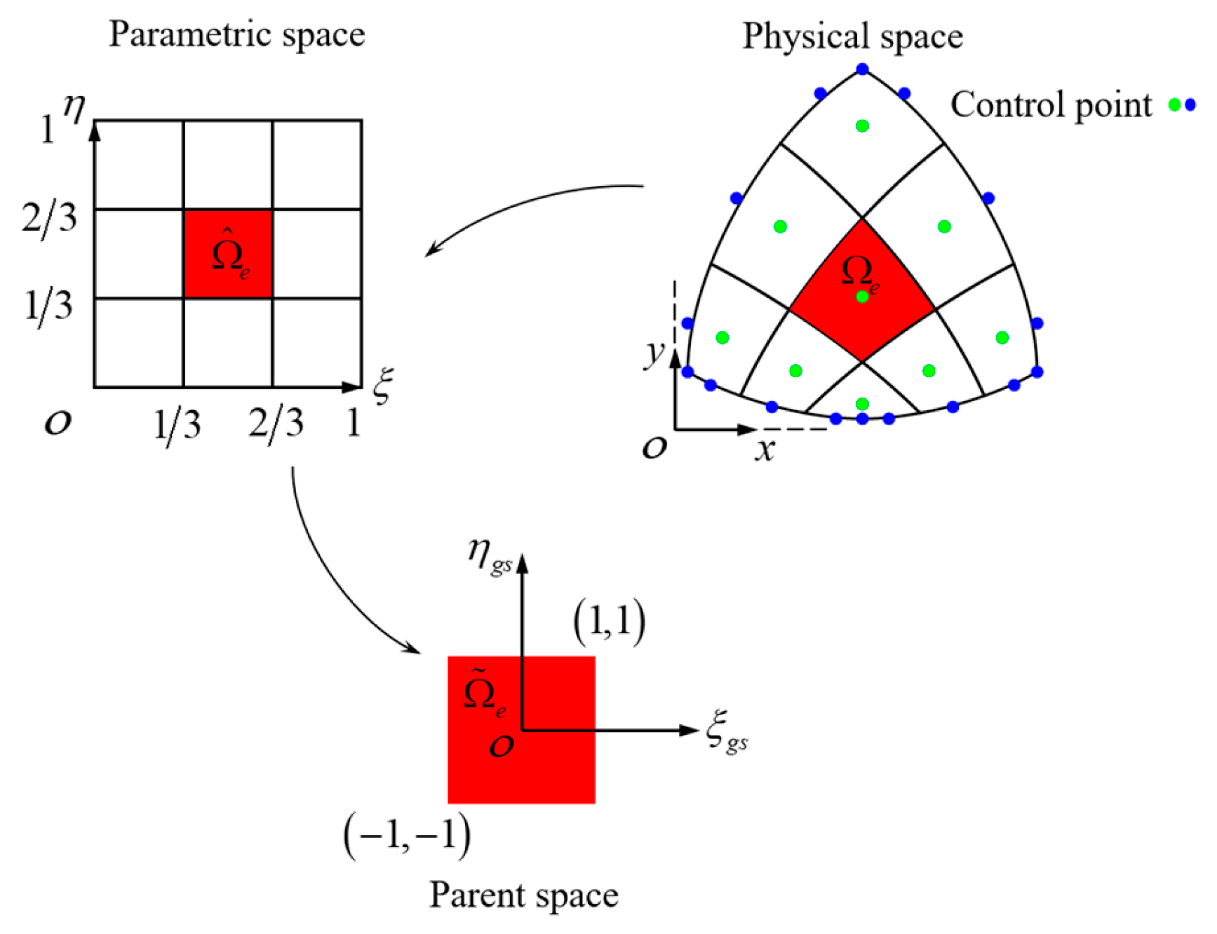
2. Isogeometric Analysis
2.1. Isogeometric Analysis for Steady State Heat Transfer Structures
2.2. Isogeometric Analysis for Static Mechanics Structures
3. MITO for Multi-Material Structure
3.1. Material Interpolation Model
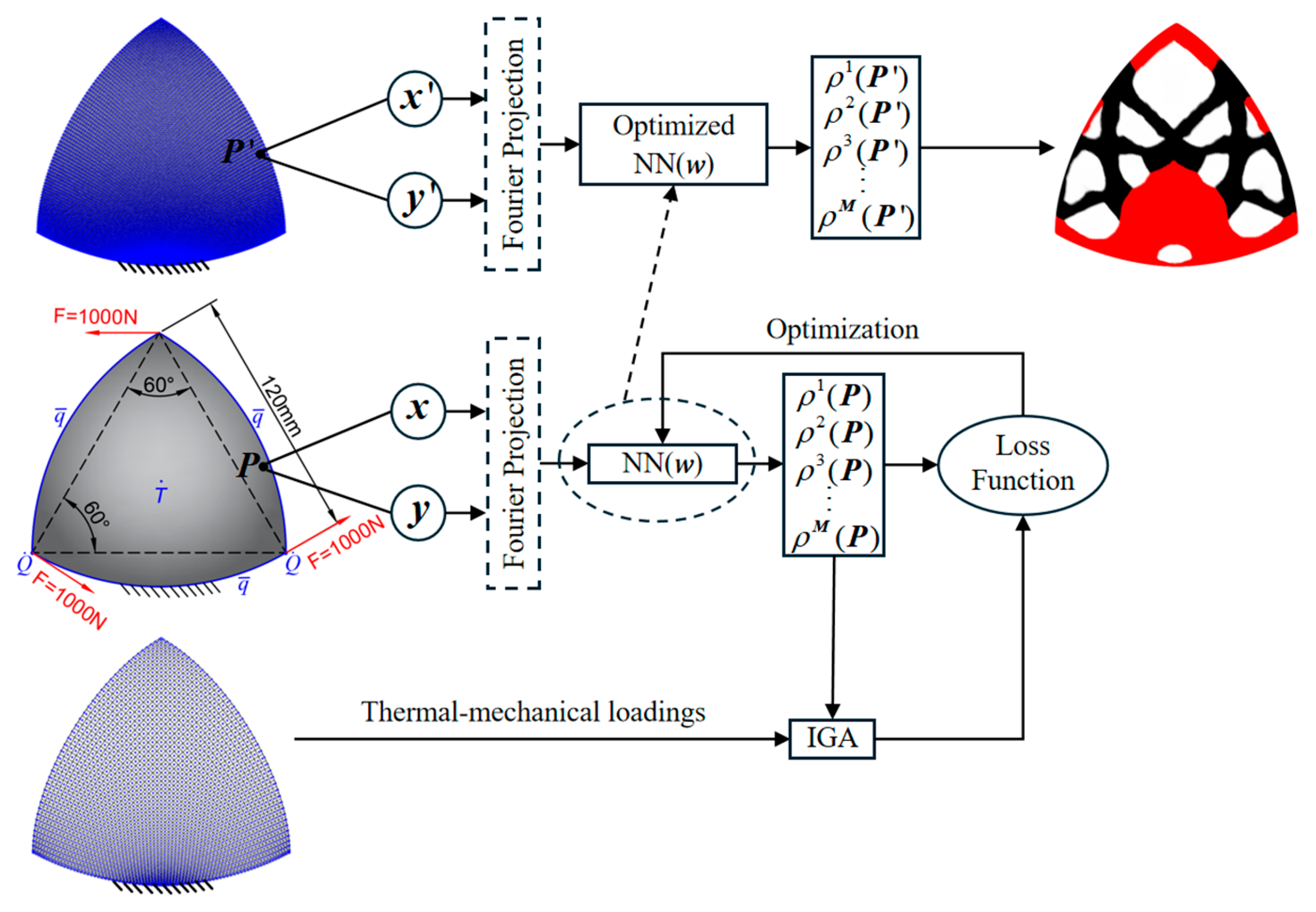
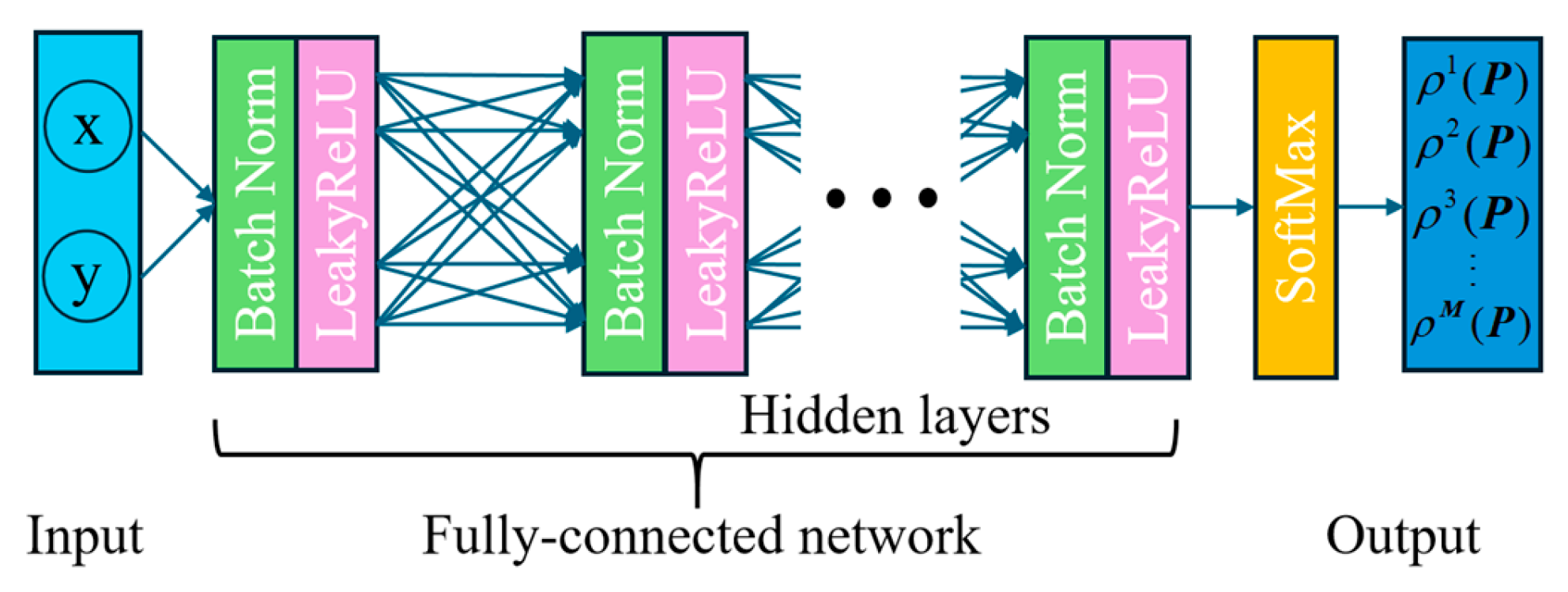
3.2. Neural Networks of MITO for Multi-Material Structures
3.3. Loss Function and Sensitivity Analysis
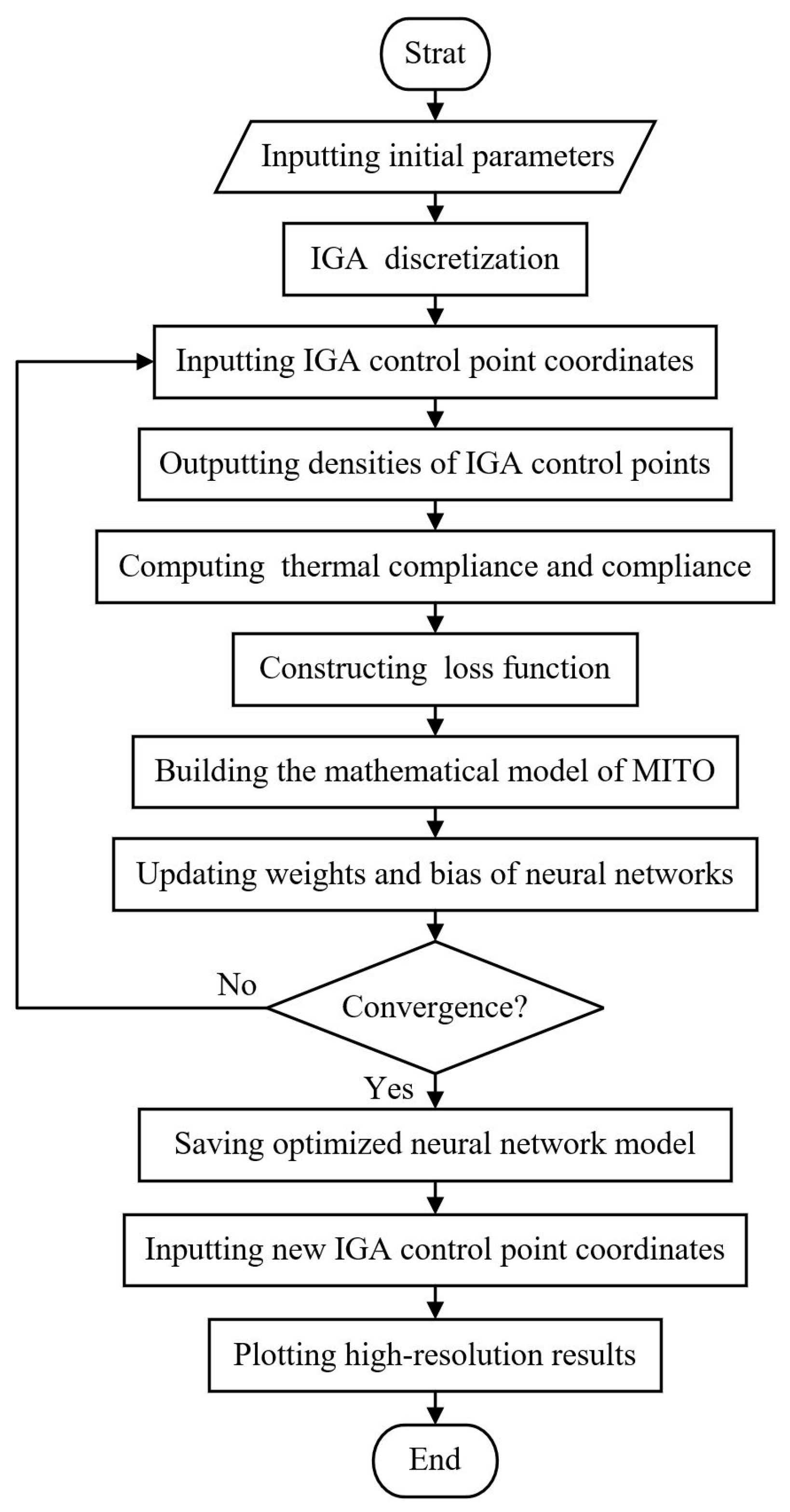
3.4. Mathematical Model and Procedure of MITO
- Input the size of neural networks (number of hidden layers and neurons) and multi-material properties (elastic modulus, Poisson’s ratio, thermal conductivity);
- Determine the initial design domain, volume constraints, weighting coefficients, maximum and minimum values of compliance, maximum and minimum values of thermal compliance, IGA parameter nodes, and control point coordinates for the multi-material structure;
- Set the number of IGA refinement nodes and perform IGA discretization of the multi-material structure;
- Construct loss function and initialize penalty factor, weights, and bias of neural networks;
- Input IGA control point coordinates to the neural networks and perform Fourier mapping;
- Output the relative densities of various materials at the IGA control points;
- Determinate the IGA overall force loading, boundary, and displacement conditions for the design domain;
- Assemble the IGA overall stiffness matrix, establish the IGA discrete governing equation for the 2-D elasticity problem, and solve the displacements at the IGA control points;
- Calculate compliance under the current material density distribution using IGA;
- Determinate the IGA overall thermal loading and thermal boundary conditions for the design domain;
- Assemble the IGA overall thermal stiffness matrix, establish the IGA discrete governing equation for the steady state heat transfer problem, and solve the temperature at the IGA control points;
- Calculate thermal compliance under the current structural density distribution using IGA;
- Establish the mathematical model for MITO of multi-material structures;
- Calculate the loss function and perform backpropagation of the neural networks;
- Update the material penalty factor and the volume penalty factor in the loss function;
- Judge the condition of iteration termination, if the condition is satisfied, get the optimized neural network model and go to the next step, if not, turn to step 5 and the aforementioned loop should be repeated until the condition is met;
- Set a higher number of IGA refinement nodes, input new IGA control point coordinates into the optimized neural network model, and output the high-resolution optimal topologies.
4. Numerical Examples
4.1. Michell Beam
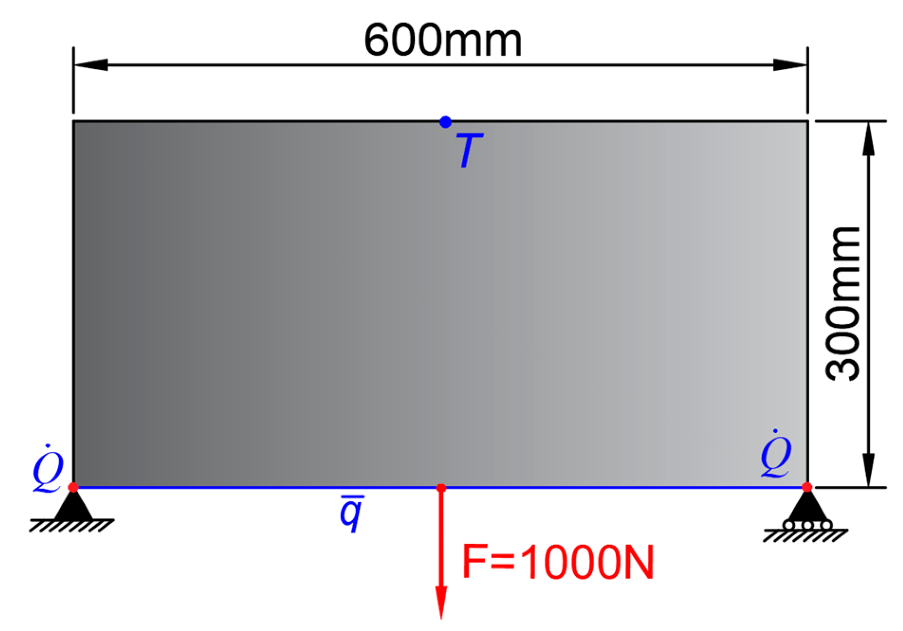
4.2. Reuleaux Triangular Structure
5. Conclusions
Author Contributions
Funding
Data Availability Statement
Conflicts of Interest
References
- Nakagawa, M.; Noguchi, Y.; Matsushima, K.; Yamada, T. Level Set-Based Multiscale Topology Optimization for a Thermal Cloak Design Problem Using the Homogenization Method. Int. J. Heat Mass Transf. 2023, 207, 123964. [Google Scholar] [CrossRef]
- Azari Nejat, A.; Held, A.; Trekel, N.; Seifried, R. A Modified Level Set Method for Topology Optimization of Sparsely-Filled and Slender Structures. Struct. Multidiscip. Optim. 2022, 65, 85. [Google Scholar] [CrossRef]
- Xie, L.; Zhang, Y.; Ge, M.; Zhao, Y. Topology Optimization of Heat Sink Based on Variable Density Method. Energy Rep. 2022, 8, 718–726. [Google Scholar] [CrossRef]
- Xu, Q.; Duan, Z.; Yan, H.; Geng, D.; Du, H.; Yan, J.; Li, H. Deep Learning-Driven Topology Optimization for Heat Dissipation of Integrated Electrical Components Using Dual Temperature Gradient Learning and MMC Method. Int. J. Mech. Mater. Des. 2023, 20, 291–316. [Google Scholar] [CrossRef]
- Kamiński, M. Uncertainty Analysis in Solid Mechanics with Uniform and Triangular Distributions Using Stochastic Perturbation-Based Finite Element Method. Finite Elem. Anal. Des. 2022, 200, 103648. [Google Scholar] [CrossRef]
- Lukáš, D.; Of, G.; Zapletal, J.; Bouchala, J. A Boundary Element Method for Homogenization of Periodic Structures. Math. Methods Appl. Sci. 2020, 43, 1035–1052. [Google Scholar] [CrossRef]
- Markopoulos, A.P.; Karkalos, N.E.; Papazoglou, E.-L. Meshless Methods for the Simulation of Machining and Micro-Machining: A Review. Arch. Comput. Methods Eng. 2020, 27, 831–853. [Google Scholar] [CrossRef]
- Hughes, T.J.R.; Cottrell, J.A.; Bazilevs, Y. Isogeometric Analysis: CAD, Finite Elements, NURBS, Exact Geometry and Mesh Refinement. Comput. Methods Appl. Mech. Eng. 2005, 194, 4135–4195. [Google Scholar] [CrossRef]
- Hassani, B.; Tavakkoli, S.M.; Moghadam, N.Z. Application of Isogeometric Analysis in Structural Shape Optimization. Sci. Iran. 2011, 18, 846–852. [Google Scholar] [CrossRef]
- Nguyen, V.P.; Anitescu, C.; Bordas, S.P.A.; Rabczuk, T. Isogeometric Analysis: An Overview and Computer Implementation Aspects. Math. Comput. Simul. 2015, 117, 89–116. [Google Scholar] [CrossRef]
- Seo, Y.-D.; Kim, H.-J.; Youn, S.-K. Isogeometric Topology Optimization Using Trimmed Spline Surfaces. Comput. Methods Appl. Mech. Eng. 2010, 199, 3270–3296. [Google Scholar] [CrossRef]
- He, J.; Chadha, C.; Kushwaha, S.; Koric, S.; Abueidda, D.; Jasiuk, I. Deep Energy Method in Topology Optimization Applications. Acta Mech. 2023, 234, 1365–1379. [Google Scholar] [CrossRef]
- Lee, S.; Kim, H.; Lieu, Q.X.; Lee, J. CNN-Based Image Recognition for Topology Optimization. Knowl. Based Syst. 2020, 198, 105887. [Google Scholar] [CrossRef]
- Wang, C.; Yao, S.; Wang, Z.; Hu, J. Deep Super-Resolution Neural Network for Structural Topology Optimization. Eng. Optim. 2021, 53, 2108–2121. [Google Scholar] [CrossRef]
- Raissi, M.; Perdikaris, P.; Karniadakis, G.E. Physics-Informed Neural Networks: A Deep Learning Framework for Solving Forward and Inverse Problems Involving Nonlinear Partial Differential Equations. J. Comput. Phys. 2019, 378, 686–707. [Google Scholar] [CrossRef]
- Zhang, Z.; Li, Y.; Zhou, W.; Chen, X.; Yao, W.; Zhao, Y. TONR: An Exploration for a Novel Way Combining Neural Network with Topology Optimization. Comput. Methods Appl. Mech. Eng. 2021, 386, 114083. [Google Scholar] [CrossRef]
- Chen, L.; Shen, M.-H.H. A New Topology Optimization Approach by Physics-Informed Deep Learning Process. Adv. Sci. Technol. Eng. Syst. J. 2021, 6, 233–240. [Google Scholar] [CrossRef]
- Jeong, H.; Bai, J.; Batuwatta-Gamage, C.P.; Rathnayaka, C.; Zhou, Y.; Gu, Y. A Physics-Informed Neural Network-Based Topology Optimization (PINNTO) Framework for Structural Optimization. Eng. Struct. 2023, 278, 115484. [Google Scholar] [CrossRef]
- Chandrasekhar, A.; Suresh, K. TOuNN: Topology Optimization Using Neural Networks. Struct. Multidiscip. Optim. 2021, 63, 1135–1149. [Google Scholar] [CrossRef]
- Bendsøe, M.P.; Sigmund, O. Material Interpolation Schemes in Topology Optimization. Arch. Appl. Mech. Ing. Arch. 1999, 69, 635–654. [Google Scholar] [CrossRef]
- Chandrasekhar, A.; Suresh, K. Approximate Length Scale Filter in Topology Optimization Using Fourier Enhanced Neural Networks. Comput. Aided Des. 2022, 150, 103277. [Google Scholar] [CrossRef]
- Giraldo-Londoño, O.; Mirabella, L.; Dalloro, L.; Paulino, G.H. Multi-Material Thermomechanical Topology Optimization with Applications to Additive Manufacturing: Design of Main Composite Part and Its Support Structure. Comput. Methods Appl. Mech. Eng. 2020, 363, 112812. [Google Scholar] [CrossRef]
- Ooms, T.; Vantyghem, G.; Thienpont, T.; Coile, R.V.; Corte, W.D. Compliance-Based Topology Optimization of Structural Components Subjected to Thermo-Mechanical Loading. Struct. Multidisc. Optim. 2023, 66, 126. [Google Scholar] [CrossRef]
- Chen, W.; Zheng, Y.; Wang, Y. Multi-Objective Topology Optimization Filled with Multiple Microstructures. Compos. Struct. 2023, 304, 116322. [Google Scholar] [CrossRef]


| Number of Material Types | 1 | 2 | 3 | |||
|---|---|---|---|---|---|---|
| Material | MAT-1 | MAT-1 | MAT-2 | MAT-1 | MAT-2 | MAT-3 |
| Color |  |  |  |  |  |  |
| Thermal conductivity | 200 | 200 | 2 × 10⁻² | 300 | 200 | 2 × 10⁻² |
| Elastic modulus | 5 × 10⁵ | 5 × 10⁵ | 1 × 10⁻⁸ | 8 × 10⁶ | 5 × 10⁶ | 1 × 10⁻⁸ |
| Poisson’s ratio | 0.3 | 0.3 | 0.3 | 0.3 | 0.3 | 0.3 |
| Volume fraction | 0.4 | 0.5 | 0.5 | 0.25 | 0.15 | 0.6 |
| Number of Material Types | Method | Weighting Coefficient | ||
|---|---|---|---|---|
| 0 | 0.5 | 1 | ||
| 1 | IGA- SIMP |  S = 94.4 W, C = 43.7 | 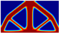 S = 74.1 W, C =45.5 | 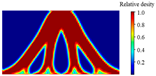 S = 62.3 W, C = 559.6 |
| IGA- NN |  S = 83.6 W, C = 41.0 |  S = 69.4 W, C = 43.5 | 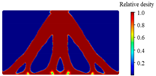 S = 61.6 W, C = 493.1 | |
| IGA- NN- Fourier |  S > 1000 W, C = 40.9 |  S = 83.2 W, C = 41.2 |  S = 61.8 W, C = 504.9 | |
| 2 | IGA- SIMP |  S = 75.2 W, C = 35.4 | 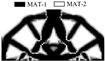 S = 72.3 W, C = 44.1 |  S = 54.6 W, C = 211.2 |
| IGA- NN | 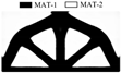 S = 67.9 W, C = 34.4 | 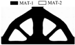 S = 62.0 W, C = 36.2 | 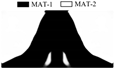 S = 56.1 W, C = 186.7 | |
| IGA- NN- Fourier | 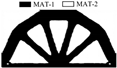 S = 71.5 W, C = 34.4 |  S = 61.1 W, C = 36.2 | 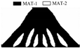 S = 55.1 W, C = 184.3 | |
| 3 | IGA- SIMP |  S = 82.6 W, C = 36.6 |  S = 81.0 W, C = 55.9 |  S = 48.4 W, C = 222.7 |
| IGA- NN |  S > 1000 W, C = 31.2 |  S = 56.3 W, C = 31.7 | 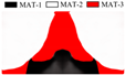 S = 48.2 W, C = 280.3 | |
| IGA- NN- Fourier |  S = 73.9 W, C = 30.8 |  S = 57.3 W, C = 31.8 | 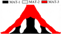 S = 45.1 W, C = 160.1 | |
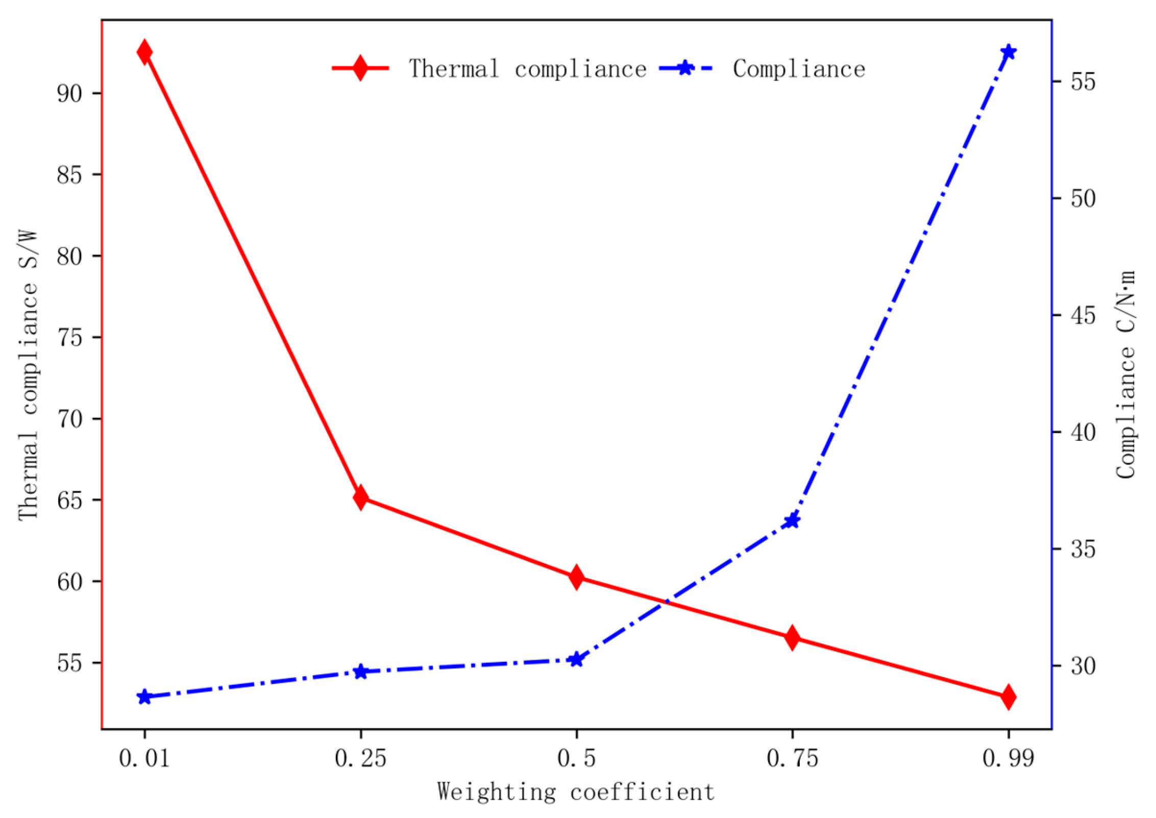
| Weighting Coefficient | Optimal Topology | Temperature Field | Displacement Field |
|---|---|---|---|
| 0.01 |  S = 92.5 W, C = 28.7 | 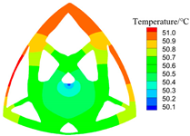 | 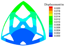 |
| 0.25 | 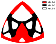 S = 65.1 W, C = 29.7 |  |  |
| 0.5 | 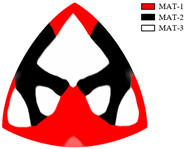 S = 60.2 W, C = 30.3 | 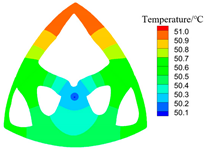 | 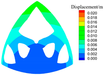 |
| 0.75 | 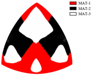 S = 56.5 W, C = 36.2 | 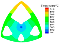 | 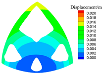 |
| 0.99 | 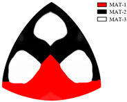 S = 52.9 W, C = 56.2 | 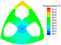 |  |
Disclaimer/Publisher’s Note: The statements, opinions and data contained in all publications are solely those of the individual author(s) and contributor(s) and not of MDPI and/or the editor(s). MDPI and/or the editor(s) disclaim responsibility for any injury to people or property resulting from any ideas, methods, instructions or products referred to in the content. |
© 2024 by the authors. Licensee MDPI, Basel, Switzerland. This article is an open access article distributed under the terms and conditions of the Creative Commons Attribution (CC BY) license (https://creativecommons.org/licenses/by/4.0/).
Share and Cite
Qiu, Y.; Xu, C.; Peng, J.; Song, Y. Isogeometric Topology Optimization of Multi-Material Structures under Thermal-Mechanical Loadings Using Neural Networks. Mathematics 2024, 12, 2350. https://doi.org/10.3390/math12152350
Qiu Y, Xu C, Peng J, Song Y. Isogeometric Topology Optimization of Multi-Material Structures under Thermal-Mechanical Loadings Using Neural Networks. Mathematics. 2024; 12(15):2350. https://doi.org/10.3390/math12152350
Chicago/Turabian StyleQiu, Yi, Cheng Xu, Jiangpeng Peng, and Yanjie Song. 2024. "Isogeometric Topology Optimization of Multi-Material Structures under Thermal-Mechanical Loadings Using Neural Networks" Mathematics 12, no. 15: 2350. https://doi.org/10.3390/math12152350
APA StyleQiu, Y., Xu, C., Peng, J., & Song, Y. (2024). Isogeometric Topology Optimization of Multi-Material Structures under Thermal-Mechanical Loadings Using Neural Networks. Mathematics, 12(15), 2350. https://doi.org/10.3390/math12152350