1. Introduction
In contrast to crawler robots, wheeled mobile robots are distinguished by their uncomplicated design, agility, flexibility, and ease of control [
1]. These attributes render them highly promising for advancement in various sectors such as industry and aerospace. Consequently, the difficulties related to motion control in wheeled mobile robots have garnered significant interest among researchers. Nevertheless, the inherent complexities of these robots, such as their high nonlinearity, multivariate nature, and strong coupling, pose significant obstacles to effective motion control.
The illustration in
Figure 1 depicts the path tracking of a wheeled mobile robot, with the solid line denoting the intended path and the dashed line indicating the robot’s actual tracking path. The visual representation highlights a significant deviation between the intended trajectory and the path executed by the robot [
2]. To enhance tracking precision and minimize errors, researchers have introduced various effective strategies for trajectory tracking control.
PID control algorithms are extensively employed as a well-established and effective method for regulating a wide range of dynamic systems. They are also suitable for addressing the trajectory tracking challenge encountered by wheeled mobile robots. For instance, a nonlinear controller is suggested in [
3] using the trajectory linearization method (TLC) for an omnidirectional mobile robot. To improve trajectory tracking precision, ref. [
4] integrate a neural network framework into the conventional PID control system to estimate the actual model of the system and dynamically optimize parameters. This integration leads to a significant improvement in trajectory tracking accuracy.
Currently, many factories utilize PID control in processing machinery to implement control algorithms. However, accurate modeling of parameters is essential for the successful application of this approach. The ideal model is often theoretical and may change during operation, making real-time adjustment of PID parameters challenging. Consequently, the sliding mode control algorithm has emerged as a viable alternative [
5,
6,
7,
8]. In [
9], a controller is developed based on the position and heading errors of a mobile robot to enable the stable tracking of circular and straight paths despite significant tracking errors and external disturbances. To tackle trajectory tracking challenges in a perturbed single-wheeled mobile robot, two new sliding variables are introduced [
10]. This leads to the development of a second-order sliding mode controller with a simple structure and efficient control performance.
As research progresses, scholars are moving beyond the mere convergence of controllers and are now seeking faster convergence rates and increased control accuracy. They are also moving away from relying on traditional mathematical models. Consequently, scholars have suggested integrating multiple control algorithms to enhance control outcomes. Examples include fuzzy PID control, inverse sliding mode control, and fuzzy adaptive sliding mode control. Sliding mode control is favored for its ability to enhance system convergence speed and mitigate interference. Therefore, combining sliding mode control with other control techniques using a hybrid sliding mode algorithm has shown promise in achieving superior control effects [
11,
12]. In a study by [
13], an adaptive neural network sliding mode control method was introduced to effectively address external disturbances by incorporating adaptive neural network techniques. Another study [
14] presents a design for a fuzzy adaptive sliding mode controller that utilizes fuzzy switching to replace the nonlinear switching term. This leads to improved tracking performance and enhanced resistance to interference. The research conducted in [
15] integrates the kinematic and dynamic models of a wheeled mobile robot to derive second-order and third-order subsystems. Subsequently, adaptive non-singular fast terminal sliding mode controllers are developed for each subsystem. Furthermore, a novel adaptive sliding mode controller based on the barrier function is proposed in [
16]. The barrier function is capable of dynamically adjusting the gain in response to disturbance magnitude, thereby enhancing the robustness of the controller.
The utilization of PID control strategies and sliding mode control techniques is outlined in
Table 1. Furthermore, the applications of a hybrid sliding mode algorithm are delineated in
Table 2.
Furthermore, aside from the aforementioned control techniques, the predominant approaches for achieving trajectory tracking in wheeled mobile robots include backstepping control methods [
17,
18,
19,
20] and predictive control methods [
21,
22,
23]. In the current body of research, the system architecture of mobile robots is commonly presented in two primary forms. One approach involves the kinematic model, which elucidates the correlation between the positional orientation of the robot and the overall velocity of the WMR (wheeled mobile robot). The other method entails the dynamics model, which delineates the connection between the WMR’s overall velocity and the disturbance torque acting upon it. The majority of scholarly works predominantly employ a single-loop control configuration, wherein the control law design directly addresses the suppression of positional orientation errors.
Based on the above literature, this study focuses on enhancing trajectory tracking performance for wheeled mobile robots by implementing sliding mode control techniques. By employing the kinematic modeling of mobile robots, the challenge of trajectory tracking is redefined as a systematic error stabilization problem. The paper introduces a sliding mode controller that integrates backstepping methodology, as well as a novel sliding mode controller. Both controllers enable the mobile robot to quickly and accurately track a predefined reference trajectory. The main contributions of this paper are as follows:
Two distinct design methodologies are employed for the development of the sliding mode controller, each of which holds significant reference value;
A continuous and differentiable function is used instead of the sign function to reduce the high-frequency oscillations that occur due to the abrupt changes in the sign function at critical points;
A novel sliding mode surface is suggested by incorporating the Lyapunov function, providing a new direction for future research.
The structure of this document is as follows. In
Section 2, the kinematic model and trajectory error model of the wheeled mobile robot are outlined. The design of the backstepping sliding mode controller and the new sliding mode controller is presented in
Section 3.
Section 4 verifies the effectiveness of the controllers. Concluding remarks are provided in
Section 5.
2. Problem Formulation
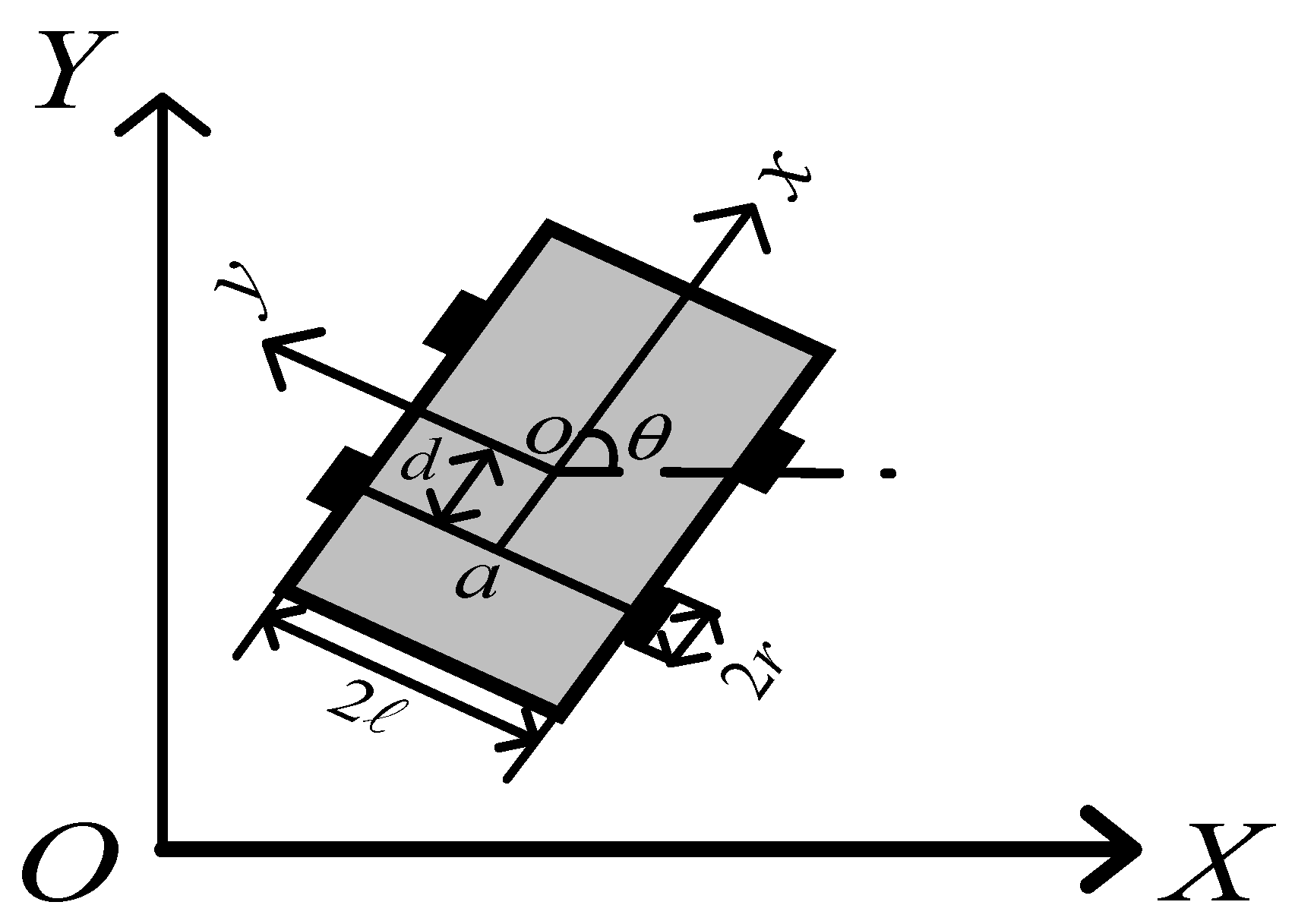
The diagram in
Figure 2 illustrates the structural configuration of the mobile robot, featuring four wheels, each powered by independent motors. A local coordinate system
is established within the framework of the wheeled mobile robot, with designated positional coordinates
. The center of the wheeled mobile robot is denoted as
, the distance between the center and the rear drive wheels in the x-direction is denoted as
, and
represents the angle between the direction of movement and the x-axis in the horizontal plane. The linear and angular velocities during the movement of the wheeled mobile robot are represented by
and
, respectively.
In order to streamline the kinematic model, it is suggested to set
equal to zero, meaning that the center of mass aligns with the geometric center. The kinematic equations of a wheeled mobile robot can be described as [
24]:
In the local coordinate system
, the position error coordinates are defined as
. The position coordinates of the mobile robot in the local coordinate system
and the global coordinate system
satisfy the following relationship:
By substituting Equation (3) into Equation (2), the positional error coordinates can be derived as shown below:
The derivation of (4) gives the differential equation for the trajectory error of the mobile robot:
3. Controller Design
3.1. Sliding Mode Controller Based on Backstepping
The backstepping control design approach is commonly employed in nonlinear systems because of its ability to integrate controller design with Lyapunov stability-based proofs, decompose complex systems into simpler subsystems, and provide a clear structure for the controller [
25]. Consequently, this method is utilized to develop the sliding mode control switching function to achieve trajectory tracking control in wheeled mobile robots.
Theorem 1. For any and bounded, , the equality sign holds if and only if .
Proof of Theorem 1. The situations of cases , and were addressed individually. In scenario , there exist ; in cases , it follows that there is a relationship where , , ; and when , there is a presence of , , . □
When
, the Lyapunov function is characterized as follows:
The derivative of
is computed as
Let
, and so there is
According to Theorem 1, holds. Therefore, when converges to 0 and converges to , the systematic error also converges to 0. At the same time, the systematic error converges to 0.
The sliding mode surface is constructed as follows:
The double power convergence rate is utilized to accelerate the convergence of the sliding mode surface towards zero, effectively eliminating tracking errors. This is represented by the following equation:
where
,
,
,
;
;
;
;
, and all are a positive odd number.
The derivation of Equations (11) and (12) and setting
results in the following expressions:
where
,
.
By integrating Equations (11) through (14), the backstepping sliding mode controller can be derived:
3.2. Novel Sliding Mode Controller
We set the slide mode surface function as
where
,
, and all are constants.
Derivation of (17) and (18) leads to
The law of dual power convergence is applicable to Equations (21) and (22):
where
;
;
;
;
, and all are a positive odd number.
The angular velocity controller for trajectory tracking is derived from Equations (5), (19), and (21):
When the sliding mode surface
converges to 0 in finite time,
is obtained. The trajectory tracking velocity controller is derived from the associative Equations (5), (20), and (22):
3.3. Convergence Time Analysis of the Systems
The presence of two power functions within the sliding mode surface poses challenges for determining the convergence time through analytical methods. As a result, an alternative approach involves establishing an upper bound for the convergence time. Assuming the initial state of the system , the convergence process can be divided into two distinct time intervals: the first period spans from the initial state to , and the second period extends from to the sliding mode surface.
It was initially demonstrated that the sliding mode surface converges to 0 within a finite duration.
Phase I:
From the initial state
to the stage
due to
,
, so in the system the second term of Equation (21) plays a dominant role in the convergence effect; ignoring the first term, the system is:
Determining the duration for the system to reach
from the initial state
involves the following calculation:
The definite integral of Equation (26) results in a solution:
The duration required to travel from
to
can be calculated using Equation (27):
As the initial term of the convergence law within the system is disregarded, the effective convergence duration of the sliding mode surface during the initial phase is shorter than .
Phase II: The system transitions from state
to the sliding mode surface. And since
,
, the primary term in the system significantly influences the convergence outcome, with the secondary term being disregarded. Consequently, the system can be expressed as
Determining the duration for the system to reach the sliding mode surface from
involves the following calculation:
The definite integral to (30) yields
The duration required for the second stage to converge can be calculated based on Equation (31):
As the second term of the convergence law within the system is disregarded, the effective convergence duration of the sliding mode surface during the subsequent phase is shorter than .
Hence, the time required for the system to reach the sliding mode surface from its initial state does not exceed .
When the initial state , the time for the system to converge to the sliding mode surface is also divided into two stages: from the initial state to and arrives at the sliding mode surface, the analysis and calculation principle is the same as that of the initial state of the system.
Similarly, it can be shown that the sliding mode surface converges to 0 in a finite time, and the convergence time is denoted as .
3.4. Convergence Time Analysis of the Systems
When
,
,
converges to 0:
The equation denoted as (5) has the potential to be converted into a different form:
The Lyapunov function is selected, as indicated by Equation (35):
The derivation of Equation (35) demonstrates that
Therefore, when
,
asymptotically converges to 0. The equation represented by (18) can be restated as
Since converges to 0 asymptotically, the sliding mode surfaces , converge to 0 in finite time, and thus also converges to 0 asymptotically. In summary, it can be seen that the trajectory tracking error , converges to 0 asymptotically under the action of the sliding mode controller based on the law of double power convergence, which converges to zero in a finite time.
3.5. Controller Improvements
In the realm of sliding mode control design, controllers are often conceptualized in an overly idealized manner. One common idealization in sliding mode control involves the utilization of the sign function term, which requires the controller to operate at an infinite switching frequency. However, in practical applications, the control device is typically non-ideal and incapable of achieving infinite switching frequencies. Consequently, the actual motion state of the sliding mode does not precisely align with the pre-defined sliding mode surface, leading to oscillations on either side of the surface, known as jitter vibration.
Jitter vibration poses various risks, such as increased energy consumption, potential damage to system hardware, and other associated hazards. Therefore, investigating methods to suppress jitter vibration in sliding mode control holds significant importance. In this section, we introduce three symbolic functions that can serve as viable alternatives to the sign function. In general, the saturation function, sigmoid function, and hyperbolic tangent function are commonly employed as alternatives to the sign function. The fundamental concept behind the saturation function approach involves the utilization of a continuous saturation function instead of a sign function. This technique involves creating a boundary layer with controlled continuity within the layer and applying normal sliding mode control outside the layer, thereby mitigating the impact of oscillations. A prevalent representation of the saturation function is depicted as follows:
where
is the boundary layer.
Similar to the saturation function, the common sigmoid function is:
Similarly, the common hyperbolic tangent function is:
In this paper, the decision was made to employ the sigmoid function in place of the sign function. By revising Equations (15), (16), (23), and (24), one can derive the enhanced backstepping sliding mode controller (BSMC) and the novel improved sliding mode controller (NSMC):
4. Simulation Results
In this section, in order to verify the effectiveness of the controller proposed in this paper, the comparative simulation experiment between BSMC, NSMC and PID utilized MATLAB/SIMULINK as the primary platform. The control structure of the wheeled mobile robot is depicted in
Figure 3.
In a simulation test, the initial position of the robot was set to be
, the initial position of the preset trajectory was set to be
, and the set reference velocity was
m/s. The controller parameters are shown in
Table 3.
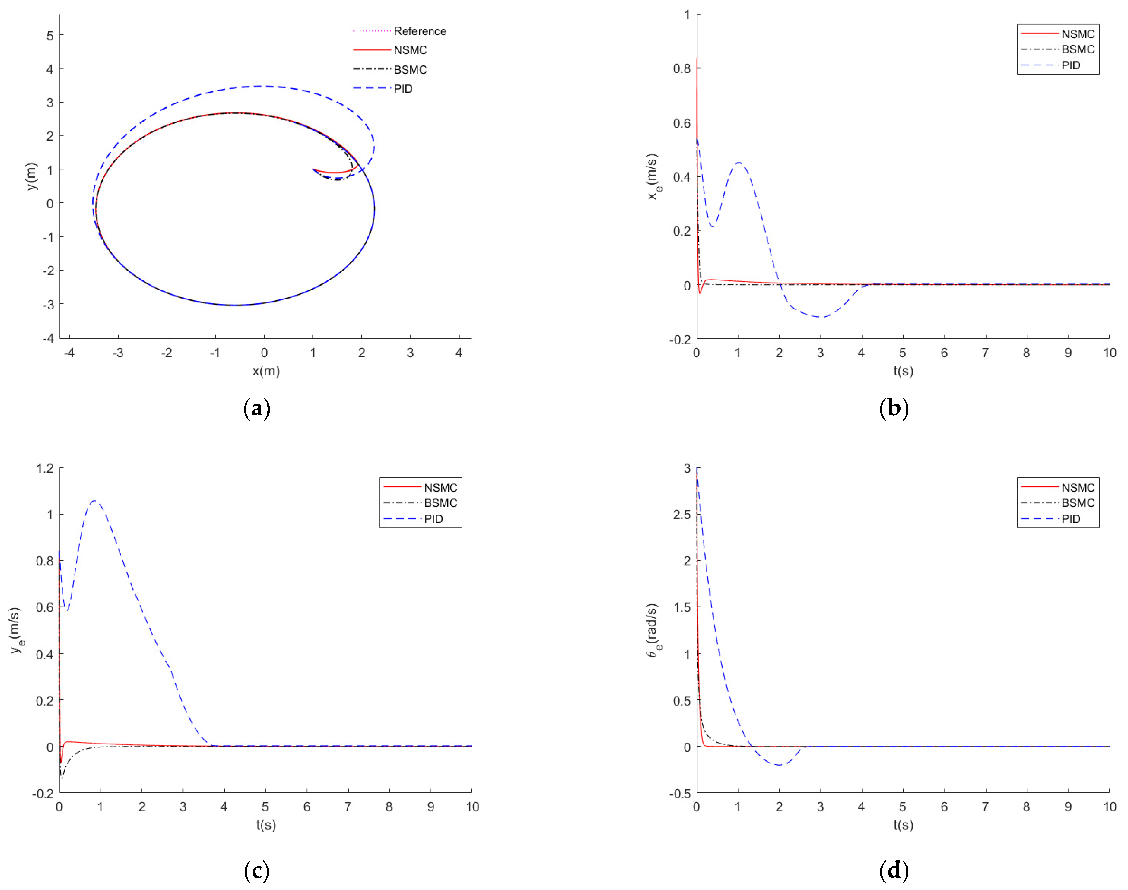
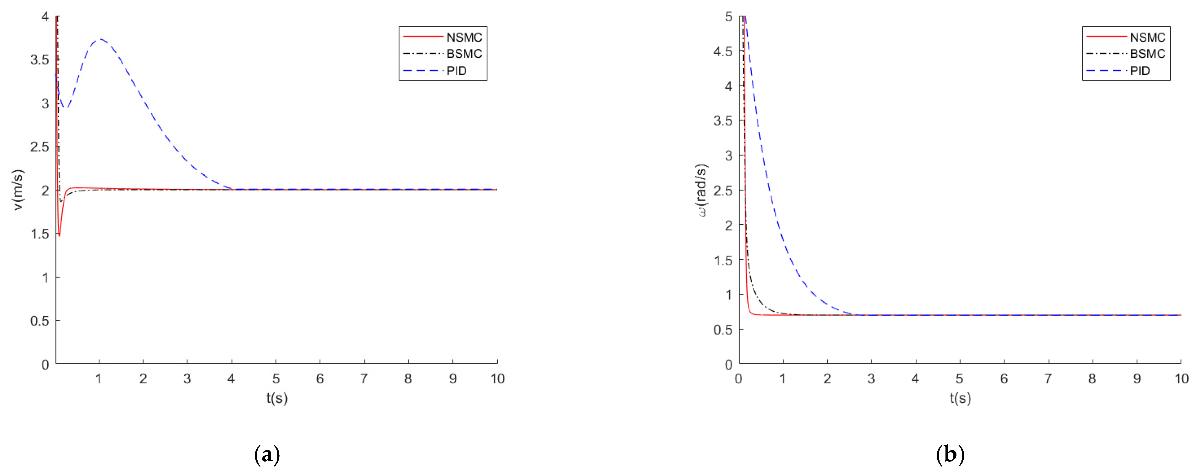
Their comparative simulation results are shown in
Figure 4 and
Figure 5. The results illustrate that both controllers can effectively track the trajectory and converge the trajectory error. The two controllers exhibit quicker convergence and achieve greater accuracy in convergence compared to the PID controller. In contrast to BSMC, NSMC can converge faster on the systematic errors
,
, but the systematic error
converges slower than BSMC. The primary distinction between NSMC and BSMC lies in the configuration of the sliding mode surface (Equations (6), (7), (17), and (18)), with different sliding mode surfaces significantly affecting the error convergence process. The design of the sliding mode surface continues to hold considerable importance for its functionality. The simulation results indicate that both BSMC and NSMC have good fast trajectory tracking control capability.
To verify the robustness of the controller to external perturbations and uncertainties, the total set of perturbations was set to be
,
. The remaining parameters were maintained at a constant level, and the aforementioned simulation experiment was replicated, with the outcomes depicted in
Figure 6 and
Figure 7.
A comparison of the control effects of NSMC and BSMC is shown in
Table 4. The convergence time refers to the moment when the trajectory tracking error decreases to below 0.02 m, and the system approaches a stable state. On the other hand, the maximum error represents the highest value of the trajectory tracking error displayed by the wheeled mobile robot during operation in a steady-state condition. On the contrary, NSMC demonstrates superior convergence speed compared to BSMC, albeit with a slightly lower level of accuracy than BSMC. Traditional PID controllers are unable to achieve trajectory tracking when disturbances are present. The NSMC and BSMC demonstrate effective regulation under various conditions, with or without external disturbances. It can be demonstrated that both controllers exhibit robust performance in the presence of external perturbations. In contrast to conventional PID control methods and traditional sliding mode control, both BSMC and NSMC exhibit enhanced performance in terms of precision of control and rate of convergence.


