Article

A Robust Fractional-Order Control Scheme for PV-Penetrated Grid-Connected Microgrid

1
Department of Mechatronics, Manipal Institute of Technology, Manipal Academy of Higher Education, Manipal 576104, India
2
School of Electrical and Electronics Engineering, SASTRA Deemed to Be University, Thanjavur 613401, India
3
Symbiosis Institute of Technology, Symbiosis International (Deemed University), Pune 412115, India
4
Department of Electrical Power and Machines, Faculty of Engineering, Alexandria University, Alexandria 21544, Egypt
5
Nagamori Actuator Research Center, Kyoto University of Advanced Science, Kyoto 6158577, Japan
6
Department of Electrical Engineering, Graphic Era (Deemed to Be University), Dehradun 248002, India
7
Applied Science Research Center, Applied Science Private University, Amman 11931, Jordan
*
Authors to whom correspondence should be addressed.
Mathematics 2023, 11(6), 1283; https://doi.org/10.3390/math11061283
Submission received: 26 January 2023 / Revised: 3 March 2023 / Accepted: 3 March 2023 / Published: 7 March 2023
(This article belongs to the Special Issue Modeling and Simulation for the Electrical Power System)

Abstract

:
This article presents a new cascaded control strategy to control the power flow in a renewable-energy-based microgrid operating in grid-connected mode. The microgrid model is composed of an AC utility grid interfaced with a multi-functional grid interactive converter (MF-GIC) acting as a grid-forming converter, a photovoltaic (PV) power-generation system acting as grid-feeding distributed generation unit, and various sensitive/non-sensitive customer loads. The proposed control strategy consists of a fractional order PI (FO-PI) controller to smoothly regulate the power flow between the utility grid, distributed generation unit, and the customers. The proposed controller exploits the advantages of FO (Fractional Order) calculus in improving the steady-state and dynamic performance of the renewable-energy-based microgrid under various operating conditions and during system uncertainties. To tune the control parameters of the proposed controller, a recently developed evaporation-rate-based water-cycle algorithm (ERWCA) is utilized. The performance of the proposed control strategy is tested under various operating conditions to show its efficacy over the conventional controller. The result shows that the proposed controller is effective and robust in maintaining all the system parameters within limits under all operating conditions, including system uncertainties.
MSC:
35B38; 74G65; 74H80

1. Introduction

Globally, the electricity demand is increasing at a rapid pace. It is customary to rely on central power utilities to meet energy needs, resulting in high T&D losses. These utilities are fueled primarily by fossil fuels and emit harmful NOX and SOX into the environment. On the contrary, power generation from renewable energy sources has several advantages, including reduced greenhouse gas emissions and economic feasibility. Expansion of transmission networks to meet growing energy needs is not always viable. Therefore, generating power locally at consumer premises (i.e., distributed generation) can benefit central utilities by reducing T&D losses and enhancing reliability [1,2,3]. Distributed generations (DGs) are mainly small-scale power generation sources such as solar PV, fuel cell, small hydro, etc. These sources became one of the efficient ways of producing power and have become an integral part of a microgrid (MG).
An MG is a group of DGs with electronic interfaces, energy storage, and various categories of loads which may function self-reliantly (islanded mode) or in tandem with the utility grid (grid-connected mode) [3,4]. The MG may interchange power with the utility while maintaining a steady frequency set by the utility grid when connected to the grid. Developing an efficient control strategy for the power electronic interfaces is necessary to establish a smooth power flow and maintain acceptable power quality. Table 1 summarizes the control techniques proposed by several researchers for controlling voltage and current in an MG.
Despite qualitative and quantitative progress in the design of controllers, the PI controller is still widely used and effective. Usually, in renewable-energy-based MGs, multiple PI controllers control the output current and voltage. The design of these controllers relies on the mathematical model of the MG and the involved power electronic interfaces [16,17,18,19]. Generally, basic approaches with linear assumptions are utilized for tuning the PI controllers. The presence of an integrator in a conventional PI controller leads to saturation and additional phase lag, which in turn affects the overall stability margin. Moreover, the PI controller cannot concurrently improve supervisory performance and disturbance rejection. Therefore, it may lead to steady-state errors when operating conditions or network parameters of the MG change [20,21,22,23].
As discussed in the literature, apart from PI controllers, various controllers, such as PR, SMC, MPC, IMC, Fuzzy-PI, etc., are implemented to control power flows in a grid-connected MG. Every control scheme has advantages and disadvantages. SMC has benefits such as swift dynamic response and resilience towards uncertainties. However, its chattering concerns might affect the steady-state performance at low switching frequencies [6]. The main drawback of fuzzy controllers is their rule-based development, which renders them computationally exhaustive and complex [7,8,9]. MPC implementation for models with significant uncertainty involves high costs and computational time [11,12].
Fractional order (FO) theory provides a versatile framework for developing robust control techniques that can effectively address various complex engineering challenges. While FO theory has been applied to various engineering fields, it has shown particular promise in the realm of energy systems, where its unique advantages can be leveraged to address the specific challenges of this domain. Recently, a few studies have been reported in the literature on the utilization of FO-based controllers for various applications such as frequency control and frequency stability enhancement of microgrids [24,25], PV and wind-integrated DC microgrid systems [26], and online frequency regulation in AC MG [26]. However, the design and implementation of FO controllers in renewable-energy-based grid-integrated MGs still need to be explored.
In an MG, the network parameters such as resistance and reactance show “fractance” behavior. Thus, it is convenient to model the dynamic behavior of an MG using fractional order (FO)-calculus rather than integer order (IO)-calculus. Due to the outweighed advantages, such as the selection of power for FO controllers, the trade-off between the first- and second-order integrator part of the controller and FO-based control usage is prevalent [27]. The integrator power in FO-PI is of fractional order, which necessitates the tuning of one additional parameter compared to IO-PI. It facilitates achieving higher flexibility in designing controllers for complex non-linear systems.
In the present work, a new dual-loop control approach comprising an FO-PI controller is proposed to effectively control the operation of a multifunctional grid-interactive converter (MF-GIC) in an MG system. The proposed dual-loop control strategy enables the MF-GIC to inject the excess power into the grid and to simultaneously offer various ancillary services, making it superior to other control approaches. The performance of the proposed control approach is validated by considering different operating conditions and uncertainties.
The proposed dual-loop control strategy requires optimizing six control parameters (three for the voltage control loop and the rest for the current control loop), which is difficult with traditional tuning methods. The difficulties in the simultaneous tuning of control parameters can be addressed effectively using optimization techniques. In the literature, various optimization techniques, such as GA, PSO, etc., are utilized for tuning the controllers [28]. This work uses an optimization technique inspired by nature, i.e., an evaporation-rate-based water cycle algorithm (ERWCA), to adjust the control parameters [29].
The uniqueness of the proposed work arises from the following:
  • A new dual-loop control approach that combines two FO-PI controllers is proposed to operate a PV-interfaced grid-connected MG effectively.
  • The proposed dual-loop control strategy enables the grid-connected MG to provide various ancillary services, even under various system operating conditions and uncertainties.
  • An ERWCA technique is implemented to estimate the fractional-order PI controller’s control parameters to efficiently exchange power flows between the utility grid and the MG.
The following sections are written as follows. In Section 2, a description of MG is given. Section 3 describes the proposed dual-loop control approach. In Section 4, ERWCA for tuning controllers is explained. In Section 5, the results are presented and discussed. Finally, the summary of the findings is given in Section 6.

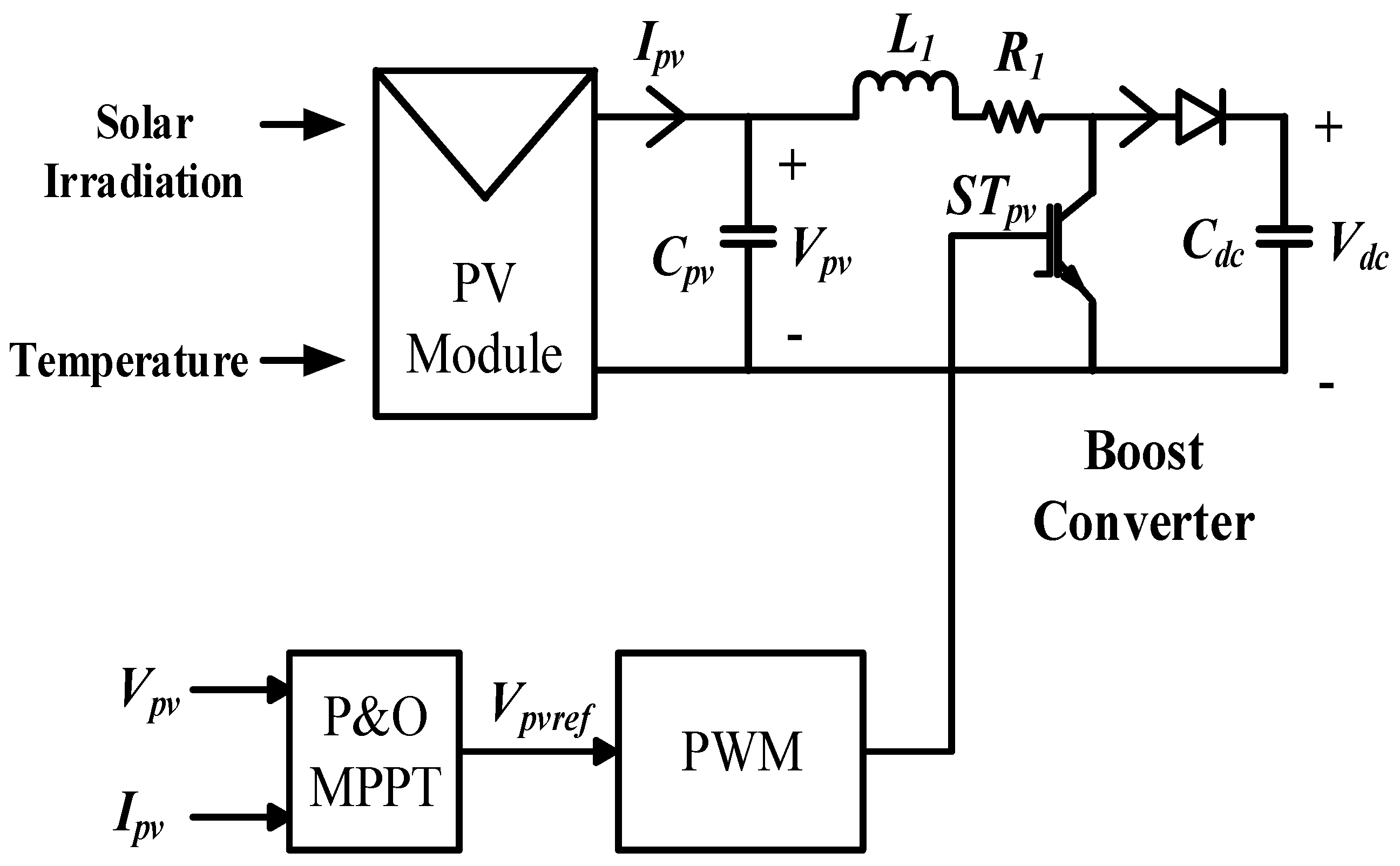
2. Grid-Connected PV System

The schematic of the grid-connected PV system is presented in Figure 1. The PV system is interconnected to the grid via MF-GIC and filter circuits. DC loads are joined at the DC link fed directly by the PV system, and all other loads are connected at the PCC. The PV system has interfaced DC-link capacitors, which help decouple it from the utility grid [9] and facilitate autonomous control of MF-GIC whenever required.

2.1. Modelling of PV System

Solar PV systems are essential for reducing greenhouse gas emissions and minimizing power-generation expenditures. The developed PV system’s modeling is based on the single-diode solar cell model. Various parameters of PV array such as solar irradiance and cell temperature are considered for the mathematical modeling to determine the power output. The developed PV system schematic is shown in Figure 2. The PV module is integrated with a P&O-based MPPT system and a DC-DC boost converter to track maximum power output. Equations (1)–(3) represent the single-diode solar cell model [9,10].
The PV system output current is represented by
I p v = N p I p h N p I s [ e x p ( q ( V p v N s + I p v R s N p ) k T c A ) 1 ]
where
I p h = [ I s c + k 1 ( T c T r e f ) ] λ 1000
The saturation current of PV cell is given by
I s = I r s ( T c T r e f ) 3 e x p [ q E g ( 1 T r e f 1 T c ) k A ]
The number of series and parallel strings are represented by Np, Ns. q, λ, and K are the electron charge, solar irradiance, and Boltzmann constant, respectively. The reference and cell temperatures are indicated by Tref, Tc. The short-circuit and reverse saturation current are given by Isc, Irs.

2.2. Reference Current Extraction

The primary goal of the designed dual-loop control technique is to exchange power between the PV system and the utility grid after supplying power to DC loads. The MF-GIC offers ancillary services such as adjusting imbalanced load and neutral currents, harmonic mitigation, and managing reactive loads. The MF-GIC can perform this multi-tasking only if an appropriate reference current is generated. Additionally, the suitable reference current aids in maintaining balance in the grid current and permissible value of THD.
The developed control strategy for generating the reference current is given in Figure 3. The excess current ( I P V * ) produced by DG is controlled only if the DC link voltage (Vdc) is maintained effectively. The maintenance of Vdc is taken care of by the proposed FO-PI controller. The load current ( i l , a b c ) and output of GIC ( i c , a b c ) are measured for generating the reference current for GIC. Equations (4) and (5) represent the active reference current ( i c d * ) and the reactive and neutral currents, respectively. The error signals produced from ( i c d * ,   i c q * , i c 0 * ) and ( i c , a b c ) will be sent to the proposed FO-PI controller. It is worth noting that an enhanced PLL (EPLL) is implemented for generating the angle (θ) for the synchronous reference frame (dq0) [30].
i c d *   =   I p v * +   i l d h
i c q *   =   i l q   ;       i c 0 *   =   i l 0

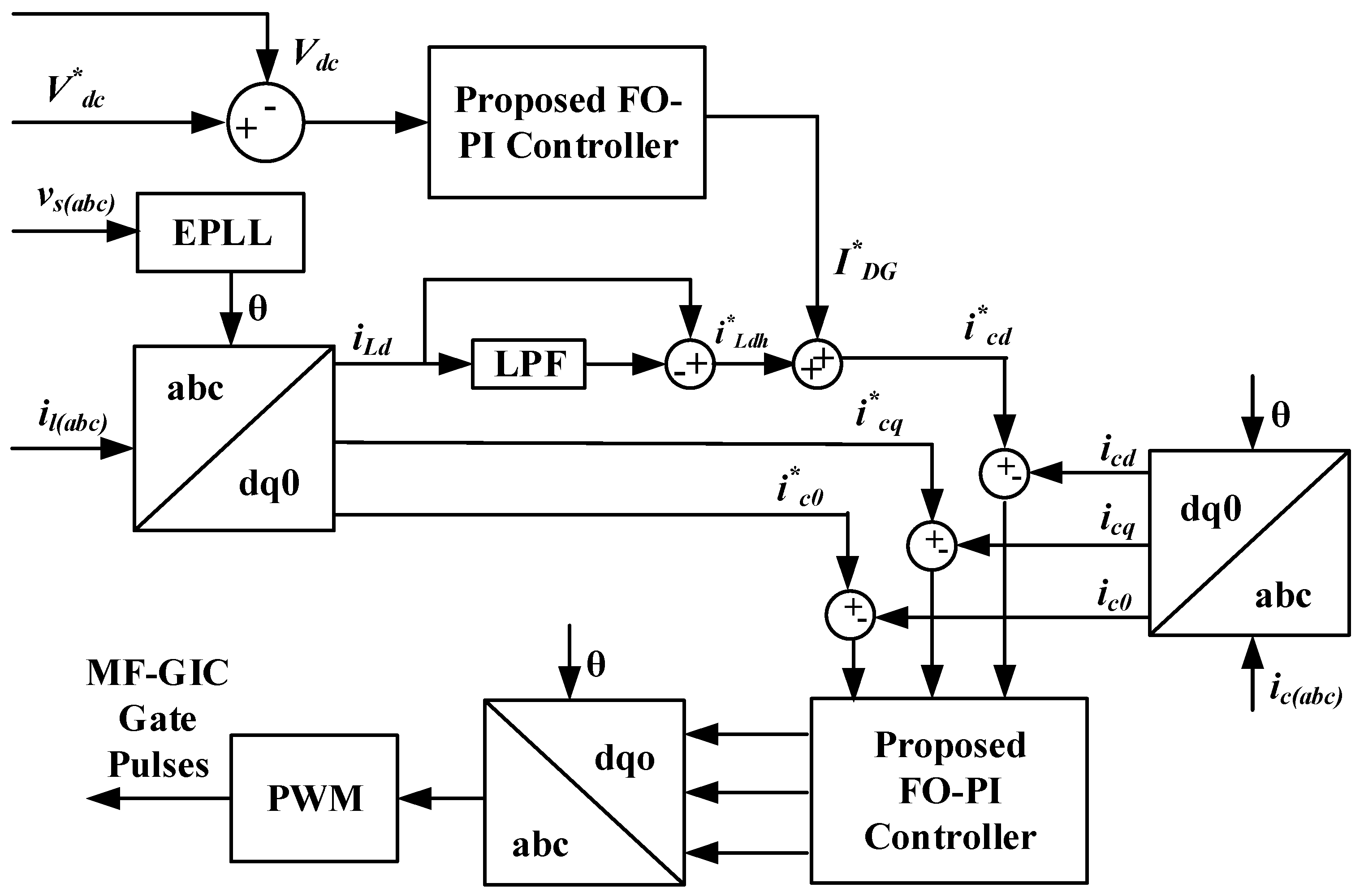
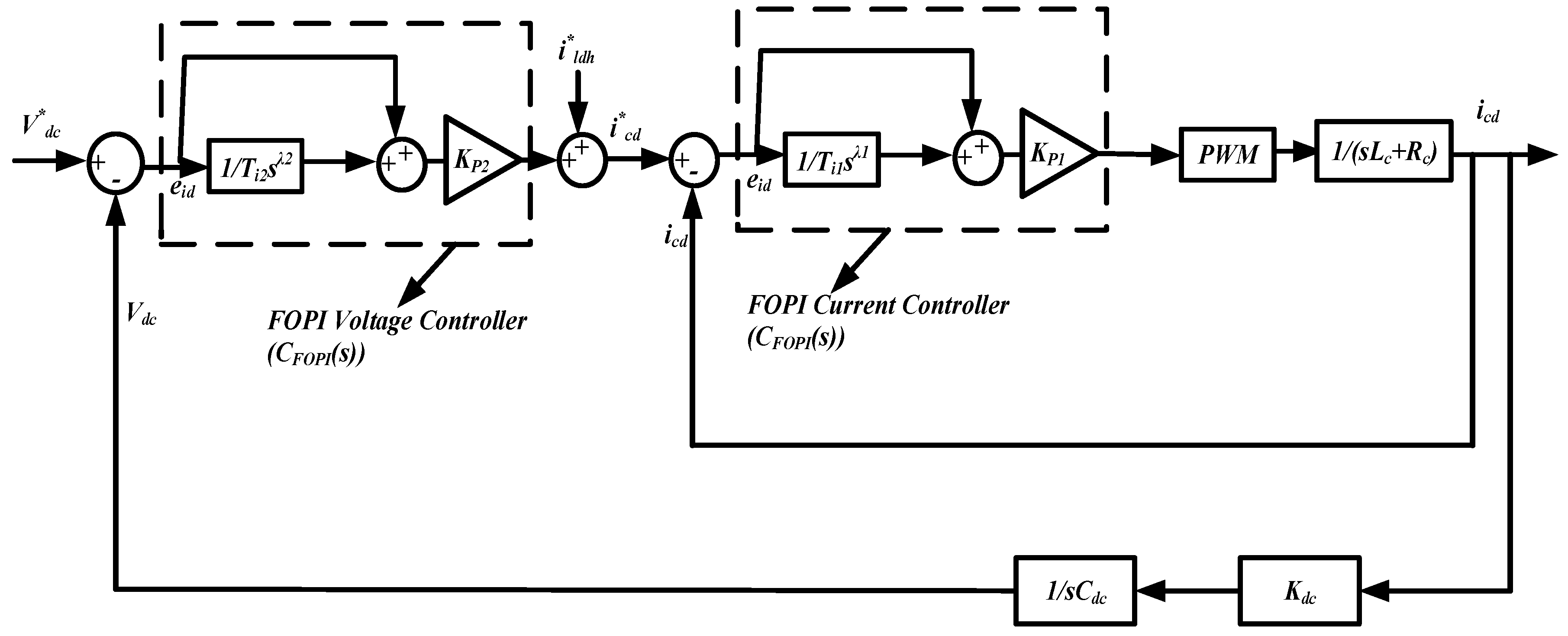
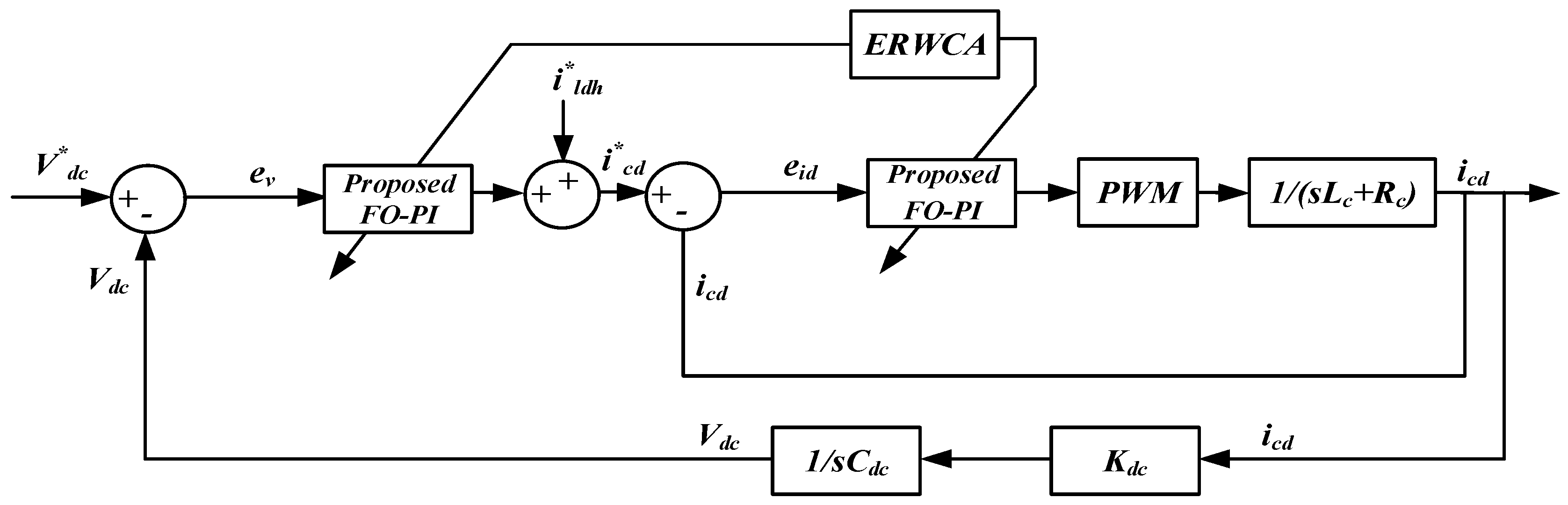
3. Proposed Cascaded FO-PI Controller for MF-GIC

Reforms in modern power systems, such as the integration of distributed energy resources, energy storage systems, etc., render these power systems increasingly complicated. Electronic interfaces controlled by conventional PI/PID controllers may not be sufficient for the efficient operation of these complex power systems. Therefore, a novel dual-loop control strategy with FO-based PI controllers is implemented for a grid-connected MG with multifunctional capabilities. Furthermore, the proposed control strategy helps in balancing the DC-link voltage and output current of MF-GIC effectively.

FO-PI-Based Voltage/Current Controller

Fractional calculus derives a non-integer order (r), fundamental operator a D t r from generalized integration and differentiation with a and t as bounds of the operator and R [31].
The integrodifferential operator is
a D t r = { d r d t r r > 0 1 r = 0 a t ( d τ ) r r < 0 }
The FO transfer function in the s-domain is represented by
G ( s ) = b m s r m + b m 1 s r m 1 + ..... + b 0 s r 0 c n s a n + c n 1 s a n 1 + ..... + c 0 s a 0 e L s
where bm, bm−1, to b0, and cn, cn−1, to c0 are the coefficients of the numerator and denominator with a delay of L for the FO transfer function. Furthermore, different definitions of fractional integrodifferential expressions are given by several authors as follows [32,33].
Grünwald–Letnikov expression,
a D t r f ( t ) = lim h 0 h r j = 0 [ t a h ] ( 1 ) j ( r j ) f ( t j h )
where
( r j ) = Γ ( r + 1 ) Γ ( j + 1 ) Γ ( r j + 1 )
Riemann–Liouville and Caputo expressions are as follows [34].
a D t r f ( t ) = 1 Γ ( n r ) d n d t n a t f ( τ ) ( t τ ) r n + 1 d τ
a D t r f ( t ) = 1 Γ ( r n ) a t f ( n ) ( τ ) ( t τ ) r n + 1 d τ
whereas n − 1 < r < n and Γ ( n ) is a popular Euler’s gamma function. By addition of a D t r f ( t ) , the differentiator and integrator can be easily unified via Equations (10) and (11).
The gamma function is as follows:
Γ ( n ) = 0 e u u n 1 d u
FO integrodifferential is developed in this paper by utilizing “approximation of Oustaloup”. This methodology uses a filter of order 2N + 1, which operates in the specified frequency spectrum [ψL, ψH,]. The FO transfer function is given by [33].
s r = M k = P P ( s + ψ z k ) ( s + ψ p k )
where M represents gain. The ψ z k   and   ψ p k , which are pole and zero frequencies, are given below [32,33].
ψ z k = ψ L ( ψ H ψ L ) k + P + ( 1 / 2 ) ( 1 r ) 2 P + 1 ψ p k = ψ L ( ψ H ψ L ) k + P + ( 1 / 2 ) ( 1 + r ) 2 P + 1
In the time domain, FO-PI is represented by
u ( t ) = K P ( 1 + 1 T i D λ ) e ( t )
Here, the fractional power and proportional and Integral gains are λ   K P ,   T I respectively.
In the s-domain,
C F O P O I ( s ) = U ( s ) E ( s ) = K P ( 1 + 1 T i   s λ )
Figure 4 depicts the fundamental block diagram of the developed cascaded FO-PI technique for MF-GIC. It involves an inner current control loop and an outer voltage control loop to regulate the DC-link voltage efficiently.

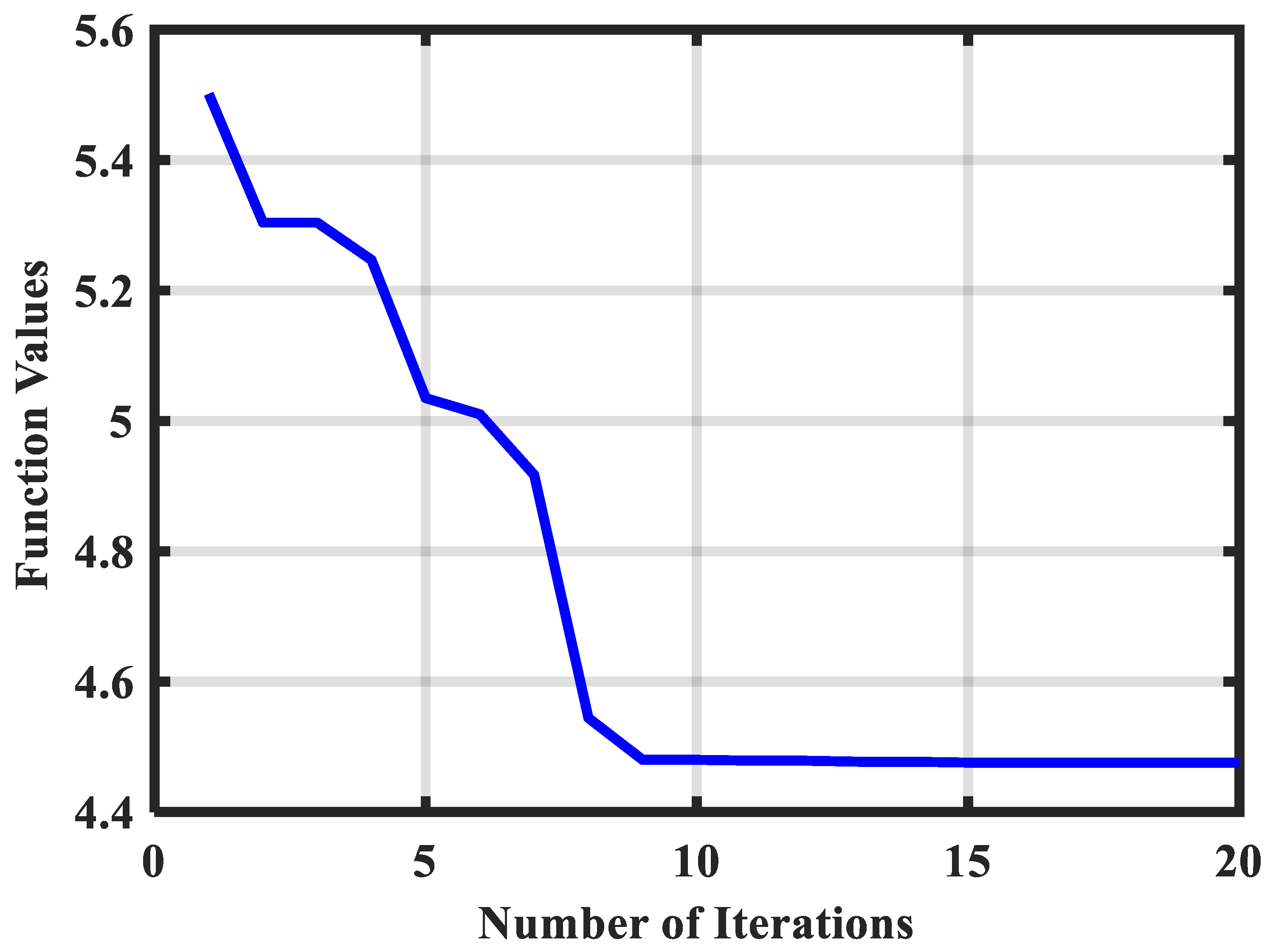
4. ERWCA Optimization

For any system, efficient and smooth operation involves determining optimal control variables. Using trial and error or traditional approaches to fine-tune control settings is time-consuming and will not produce desirable results in all operating situations. As a result, it is advantageous to use metaheuristic approaches to determine the best control settings. WCA is a metaheuristic algorithm inspired by the water cycle behavior of streams and rivers. This algorithm has been proven to be efficient in solving global unconstrained and constrained optimization problems. However, the WCA has some drawbacks, such as ease of falling into local optimum and slow convergence speed. To overcome these shortcomings, an enhanced WCA, which is associated with the evaporation rate, is developed to improve these shortcomings. This ERWCA provides a better balance between exploitation and exploration than WCA. Thus, the ERWCA metaheuristic technique is chosen to tune the controller parameters optimally [29].
The following are the main steps for implementing ERWCA:
  • Input the variables by random generation within the bounds.
  • After evaluating fitness, define the maximum fitness value as SEA and other good individuals as rivers.
  • Determine the flow rate of SEA and rivers.
  • Use below equations to merge SEA with rivers:
    X s t r e a m t + 1 = X s t r e a m t + r a n d × C × ( X R i v e r t X s t r e a m t )
    X s t r e a m t + 1 = X s t r e a m t + r a n d × C × ( X s e a t X s t r e a m t )
  • From a stream, switch between river and sea locations to find the best solution.
  • Merge the rivers with SEA using (19):
    X R i v e r t + 1 = X R i v e r t + r a n d × C × ( X s e a t X s t r e a m t )
  • Again, switch between SEA and river locations if the river offers a better solution.
  • Determine the evaporation rate using (20):
    E R = S u m ( N S n ) N s r 1 × r a n d         n = 2 ,   ...... ,   N s r
  • Update the SEA and river locations based on the ER value.
    X s t r e a m N e w ( t + 1 ) = L B + r a n d × ( U B L B )
    X s t r e a m N e w ( t + 1 ) = X s e a t + μ × r a n d ( 1 , N )
  • Once the stopping criterion is reached, terminate the ERWCA process. Otherwise, go to step 4.
The objective function chosen to determine the optimal control variable in this work is the Integral Absolute Error (IAE). Figure 5 shows the ERWCA-tuned FO-PI for voltage/current control of MF-GIC. The parameters of ERWCA considered for determining the optimal control variables are given in Table 2.

5. Results and Discussion

In this section, a comprehensive analysis of the developed dual-loop control technique for PV-based MF-GIC is presented. A detailed model of the system is implemented in MATLAB/Simulink. Table 3 provides the design parameters considered for the study. The proposed control technique is tested and validated in a multitude of scenarios as follows: (i) a sudden modification in PV power output, (ii) a sudden modification in real and reactive demand, and (iii) introducing imbalance and distortion on the grid side. It is assumed that solar irradiance and temperature are time-varying during the simulation. The switching of various types of loads is given in Table 4.
As discussed, ERWCA is applied to assess the parameters of the FO-PI controller (Kp1 = 0.89, Ki1 = 262.87, λ1 = 0.9892; Kp2 = 6.978, Ki2 = 712.30, λ2 = 0.9912). The Integral Absolute Error (IAE) is minimal with the ERWCA-tuned parameters. The convergence characteristics of ERWCA are given in Figure 6. It can be observed from Figure 6 that ERWCA converges in less than 10 iterations for the specific problem. The time-varying output power of the PV array is represented in Figure 7. At the starting point, the PV array produces 39 kW output, and with a change in irradiance, the output power is gradually reduced to 28 kW by 0.9 s, which is maintained until 1.6 s. Later, it rises to 36.2 kW for the rest of the period. Figure 8 illustrates the equivalent PV output voltage and current. The P&O algorithm can track variations in irradiance and aim to enhance power output from the PV system. Figure 9 depicts the comparison of the MF-GIC voltage with PI. The proposed controller’s tracking performance and disturbance rejection outperform the conventional PI controller during various disturbances. Furthermore, it offers an excellent response with a reduced peak and a quicker settling time under all operating conditions.
Figure 10 depicts the actual power output of the utility grid. Initially, the power generated from the PV system is supplied to the loads, and the surplus power is injected into the utility grid. With gradual changes in solar irradiance, the FO-PI controller regulates the power flows effectively throughout the period. The FO-PI controller is efficient in controlling the power during sudden changes in MG load demand. At approximately 0.8 s, due to a deficit in output power from the PV system, the utility injects the real power desired by the load. The proposed FO-PI controller provides better dynamic and transient performance during these transitions. Table 5 compares performance indices such as peak time, settling time, and rise time through the PI controller to illustrate the superiority of the proposed FO-PI controller. In addition, the results are compared with existing control approaches reported in the literature. The table verifies that the proposed FO-PI controller has a lower overshoot and settling time when compared to other controllers. The overall IAE and ITAE are low in the case of the proposed controller under all operational conditions.
Figure 11 depicts the MF-GIC’s real power output. At t = 0.3 s, an additional DC load is connected to the system, which necessitates effective regulation of the power output from the PV system and the utility grid suddenly. This disturbance at the DC side is effectively handled by the FO-PI controller in terms of the overshoot and settling time compared to the PI controller. The comparison of active, current reference tracking errors between PI and FO-PI is presented in Figure 12. The PI controller has a prominent steady-state error while tracking active current references, whereas the FO-PI controller offers a negligible error.
Due to the presence of non-linear loads and three-AC loads, the reactive power demand in the system increases abruptly. The MF-GIC can effectively handle this without relying on a utility grid and additional active filters. The reactive power from the grid is effectively regulated and maintained close to zero with less oscillations by the FO-PI controller when compared to PI, which can be observed from Figure 13 and Figure 14, respectively. Therefore, it is proven that the proposed dual-loop control strategy effectively provides reactive power compensation aside from its core purpose of controlling power flows. The reactive current tracking of FO-PI and traditional PI is shown in Figure 15. It is seen that FO-PI offers better tracking with fewer oscillations compared to the PI controller.
The existence of non-linear loads in an MG leads to the flow of neutral currents in the system, which is undesirable. The proposed control strategy automatically takes care of this issue without additional equipment. The neutral current waveforms of load, GIC, and utility grid are shown in Figure 16. The load neutral current is compensated effectively by the MF-GIC and maintains zero neutral currents at the utility.
The three-phase current waveforms of load, utility, and MF-GIC are presented in Figure 17. The grid current is sinusoidal and balanced with a THD of 0.81% in the presence of an unbalanced and distorted load current. As a result, it is possible to conclude that the proposed control strategy has multifunctional capabilities in offering ancillary services.
The study is advanced with the inclusion of distortions and grid-side imbalance to verify the robustness of the developed dual-loop control technique. Figure 18 depicts the distorted and imbalanced grid voltage used in the study. Figure 19 and Figure 20 illustrate the grid current and GIC current waveforms acquired using the proposed FO-PI and conventional PI, respectively. The developed dual-loop control technique efficiently mitigates grid voltage disturbances and maintains sinusoidal grid current with a THD of 1.30 percent. Under this case, the PI controller fails to keep the grid current sinusoidal, as seen in Figure 20. In this situation, the THD is estimated to be roughly 10.58 percent. This demonstrates the strength of the proposed dual-loop control technique with a cascaded FO-PI in dealing with grid-side uncertainties.

6. Conclusions

Due to the uncertain nature of renewable energy resources, regulating power flows in a microgrid is quite challenging. To effectively handle this issue, a new dual-loop control strategy consisting of an FO-PI controller is proposed in this paper for controlling the MF-GIC. The efficacy of the proposed controller is investigated on a grid-connected PV system consisting of balanced, unbalanced, and non-linear loads. Various operating conditions such as sudden changes in PV power output, power demand, and disturbances on the grid side are considered. The results show that, with the proposed control approach, the steady-state performance of the renewable energy microgrid in controlling the active and reactive power flow is improved significantly. The dynamic performance is also enhanced with the proposed control scheme during various operating conditions. The proposed control strategy significantly improves settling time and reduces overshoot and oscillations during disturbances. In addition to this, the MF-GIC has offered various ancillary services such as reactive power compensation, mitigation of load current harmonics, and unbalanced load and neutral current compensation to maintain good power quality. For future work, the effect of adding constant power loads to the microgrid needs to be explored. Constant power loads often bring stability issues due to their negative impedance characteristics. Hence, the effect of the proposed control approach can be explored by including the impact of constant power loads.

Author Contributions

Conceptualization, N.P., V.T. and V.S.; Methodology, N.P., V.T. and M.P.K.; Software, N.P., V.T. and V.S.; Validation, N.P., V.T., M.P.K. and V.S.; Formal analysis, N.P., V.T., H.K. and V.S.; Investigation, N.P., V.T., V.S. and R.N.T.; Resources, N.P., V.T., M.P.K. and M.B.; Data curation, N.P., V.T., V.S., R.N.T. and M.B.; Writing—original draft, N.P., V.T., H.K. and V.S.; Writing—review and editing, N.P., V.T. and V.S.; Visualization, M.P.K., V.T. and V.S.; Supervision, H.K., R.N.T. and M.B.; Project administration, H.K., R.N.T. and M.B.; Funding acquisition, R.N.T. All authors have read and agreed to the published version of the manuscript.

Funding

This research received no external funding.

Institutional Review Board Statement

Not applicable.

Informed Consent Statement

Not applicable.

Data Availability Statement

The data sources employed for analysis are presented in the text.

Conflicts of Interest

The authors declare no conflict of interest.

Abbreviations

APIAdaptive PI Control
DGDistributed Generation
ERWCAEvaporation-Rate-based Water Cycle Algorithm
FLCFuzzy-Logic Control
FOFractional Order
FO-PIFractional Order PI
GICGrid Interactive Converter
IAEIntegral Absolute Error
IMCInternal Model Control
IMPCInternal Model Predictive Control
IOInteger Order
ITAEIntegral Time Absolute Error
MF-GICMulti-functional Grid Interactive Converter
MGMicrogrid
MPCModel Predictive Control
MPPTMaximum Power Point Tracking
PCCPoint of Common Coupling
PNNCPredictive Neural Network Controller
PVPhotovoltaic
P&OPerturb & Observe
QPRQuasi-Proportional-Resonant Controller
SMCSliding-Mode Control
THDTotal Harmonic Distortion
T&DTransmission & Distribution

References

  1. Bajaj, M.; Singh, A.K. Grid integrated renewable DG systems: A review of power quality challenges and state-of-the-art mitigation techniques. Int. J. Energy Res. 2020, 44, 26–69. [Google Scholar] [CrossRef]
  2. Dharavat, N.; Sudabattula, S.K.; Velamuri, S.; Mishra, S.; Sharma, N.K.; Bajaj, M.; Elgamli, E.; Shouran, M.; Kamel, S. Optimal Allocation of Renewable Distributed Generators and Electric Vehicles in a Distribution System Using the Political Optimization Algorithm. Energies 2022, 15, 6698. [Google Scholar] [CrossRef]
  3. Akhavan, A.; Golestan, S.; Vasquez, J.C.; Guerrero, J.M.; Xie, C. Stability Enhancement of Inverters in Grid-Connected Microgrids Using FIR Filter. IEEE J. Emerg. Sel. Top. Ind. Electron. 2021, 2, 122–131. [Google Scholar] [CrossRef]
  4. Dashtdar, M.; Bajaj, M.; Hosseinimoghadam, S.M.S. Design of Optimal Energy Management System in a Residential Microgrid Based on Smart Control. Smart Sci. 2022, 10, 25–39. [Google Scholar] [CrossRef]
  5. Malakondareddy, B.; Kumar, S.S.; Gounden, N.A.; Anand, I. An adaptive PI control scheme to balance the neutral-point voltage in a solar PV fed grid connected neutral point clamped inverter. Int. J. Electr. Power Energy Syst. 2019, 110, 318–331. [Google Scholar] [CrossRef]
  6. Safa, A.; Berkouk, E.M.; Messlem, Y.; Gouichiche, A. A robust control algorithm for a multifunctional grid tied inverter to enhance the power quality of a microgrid under unbalanced conditions. Int. J. Electr. Power Energy Syst. 2019, 100, 253–264. [Google Scholar] [CrossRef]
  7. Roselyn, J.P.; Chandran, C.P.; Nithya, C.; Devaraj, D.; Venkatesan, R.; Gopal, V.; Madhura, S. Design and implementation of fuzzy logic based modified real-reactive power control of inverter for low voltage ride through enhancement in grid connected solar PV system. Control Eng. Pract. 2020, 101, 104494. [Google Scholar] [CrossRef]
  8. Arcos-Aviles, D.; Pascual, J.; Guinjoan, F.; Marroyo, L.; Garcia-Gutierrez, G.; Gordillo-Orquera, R.; Llanos-Proaño, J.; Sanchis, P.; Motoasca, T.E. An Energy Management System Design Using Fuzzy Logic Control: Smoothing the Grid Power Profile of a Residential Electro-Thermal Microgrid. IEEE Access 2021, 9, 25172–25188. [Google Scholar] [CrossRef]
  9. Vigneysh, T.; Kumarappan, N. Grid interconnection of renewable energy sources using multifunctional grid-interactive converters: A fuzzy logic-based approach. Electr. Power Syst. Res. 2017, 151, 359–368. [Google Scholar] [CrossRef]
  10. Mohamed, A.A.; Metwally, H.; El-Sayed, A.; Selem, S.I. Predictive neural network based adaptive controller for grid-connected PV systems supplying pulse-load. Sol. Energy 2019, 193, 139–147. [Google Scholar] [CrossRef]
  11. Mohapatra, S.R.; Agarwal, V. Model Predictive Control for Flexible Reduction of Active Power Oscillation in Grid-tied Multilevel Inverters under Unbalanced and Distorted Microgrid Conditions. IEEE Trans. Ind. Appl. 2019, 56, 1107–1115. [Google Scholar] [CrossRef]
  12. Saleh, A.; Deihimi, A.; Iravani, R. Model predictive control of distributed generations with feed-forward output currents. IEEE Trans. Smart Grid 2017, 10, 1488–1500. [Google Scholar] [CrossRef]
  13. Ye, T.; Dai, N.; Lam, C.S.; Wong, M.C.; Guerrero, J.M. Analysis, design, and implementation of a quasi-proportional-resonant controller for a multifunctional capacitive-coupling grid-connected inverter. IEEE Trans. Ind. Appl. 2016, 52, 4269–4280. [Google Scholar] [CrossRef] [Green Version]
  14. Zou, Z.; Wang, Z.; Cheng, M. Modeling, analysis, and design of multifunction grid-interfaced inverters with output LCL filter. IEEE Trans. Power Electron. 2013, 29, 3830–3839. [Google Scholar] [CrossRef]
  15. Leitner, S.; Yazdanian, M.; Ziaeinejad, S.; Mehrizi-Sani, A.; Muetze, A. Internal model-based active resonance damping current control of a grid-connected voltage-sourced converter with an LCL filter. IEEE Trans. Power Syst. 2018, 33, 6025–6036. [Google Scholar] [CrossRef]
  16. Zeng, Z.; Li, H.; Tang, S.; Yang, H.; Zhao, R. Multi-objective control of multi-functional grid-connected inverter for renewable energy integration and power quality service. IET Power Electron. 2016, 9, 761–770. [Google Scholar] [CrossRef]
  17. Pouresmaeil, E.; Miguel-Espinar, C.; Massot-Campos, M.; Montesinos-Miracle, D.; Gomis-Bellmunt, O. A control technique for integration of DG units to the electrical networks. IEEE Trans. Ind. Electron. 2012, 60, 2881–2893. [Google Scholar] [CrossRef]
  18. Bai, W.; Abedi, M.R.; Lee, K.Y. Distributed generation system control strategies with PV and fuel cell in microgrid operation. Control Eng. Pract. 2016, 53, 184–193. [Google Scholar] [CrossRef]
  19. Patankar, P.P.; Munshi, M.M.; Deshmukh, R.R.; Ballal, M.S. A Modified Control Method for Grid Connected Multiple Rooftop Solar Power Plants. IEEE Trans. Ind. Appl. 2021, 57, 3306–3316. [Google Scholar] [CrossRef]
  20. Li, H.; Ding, X.; Xue, R.; Li, G.; Chen, Y. Active Damping Adaptive Controller for Grid-Connected Inverter Under Weak Grid. IEEE Access 2021, 9, 132442–132454. [Google Scholar] [CrossRef]
  21. Prasad, T.N.; Devakirubakaran, S.; Muthubalaji, S.; Srinivasan, S.; Karthikeyan, B.; Palanisamy, R.; Bajaj, M.; Zawbaa, H.M.; Kamel, S. Power management in hybrid ANFIS PID based AC–DC microgrids with EHO based cost optimized droop control strategy. Energy Rep. 2022, 8, 15081–15094. [Google Scholar] [CrossRef]
  22. Dashtdar, M.; Nazir, M.S.; Hosseinimoghadam, S.M.S.; Bajaj, M.; Srikanth Goud, B. Improving the Sharing of Active and Reactive Power of the Islanded Microgrid Based on Load Voltage Control. Smart Sci. 2022, 10, 142–157. [Google Scholar] [CrossRef]
  23. Suresh, V.; Pachauri, N.; Vigneysh, T. Decentralized control strategy for fuel cell/PV/BESS based microgrid using modified fractional order PI controller. Int. J. Hydrogen Energy 2021, 46, 4417–4436. [Google Scholar] [CrossRef]
  24. Khosravi, N.; Abdolvand, A.; Oubelaid, A.; Khan, Y.A.; Bajaj, M.; Govender, S. Improvement of power quality parameters using modulated-unified power quality conditioner and switched-inductor boost converter by the optimization techniques for a hybrid AC/DC microgrid. Sci. Rep. 2022, 12, 21675. [Google Scholar] [CrossRef]
  25. Long, B.; Li, X.; Rodriguez, J.; Guerrero, J.M.; Chong, K.T. Frequency stability enhancement of an islanded microgrid: A fractional-order virtual synchronous generator. Int. J. Electr. Power Energy Syst. 2023, 147, 108896. [Google Scholar] [CrossRef]
  26. Mohammadzadeh, A.; Kayacan, E. A novel fractional-order type-2 fuzzy control method for online frequency regulation in ac microgrid. Eng. Appl. Artif. Intell. 2020, 90, 103483. [Google Scholar] [CrossRef]
  27. Mohapatra, B.; Sahu, B.K.; Pati, S.; Bajaj, M.; Blazek, V.; Prokop, L.; Misak, S.; Alharthi, M. Real-Time Validation of a Novel IAOA Technique-Based Offset Hysteresis Band Current Controller for Grid-Tied Photovoltaic System. Energies 2022, 15, 8790. [Google Scholar] [CrossRef]
  28. Jaiswal, A.; Belkhier, Y.; Chandra, S.; Priyadarshi, A.; Bajaj, M.; Pushkarna, M.; Elgamli, E.; Shouran, M.; Kamel, S. Design and Implementation of Energy Reshaping Based Fuzzy Logic Control for Optimal Power Extraction of PMSG Wind Energy Converter. Front. Energy Res. 2022, 10, 966975. [Google Scholar] [CrossRef]
  29. Sadollah, A.; Eskandar, H.; Bahreininejad, A.; Kim, J.H. Water cycle algorithm with evaporation rate for solving constrained and unconstrained optimization problems. Appl. Soft Comput. 2015, 30, 58–71. [Google Scholar] [CrossRef]
  30. Ghoshal, A.; John, V. A method to improve PLL performance under abnormal grid conditions. Proc. NPEC 2007, 7, 17–19. [Google Scholar]
  31. Ouari, K.; Belkhier, Y.; Djouadi, H.; Kasri, A.; Bajaj, M.; Alsharef, M.; Elattar, E.E.; Kamel, S. Improved nonlinear generalized model predictive control for robustness and power enhancement of a DFIG-based wind energy converter. Front. Energy Res. 2022, 10, 996206. [Google Scholar] [CrossRef]
  32. Pachauri, N.; Yadav, J.; Rani, A.; Singh, V. Modified fractional order IMC design based drug scheduling for cancer treatment. Comput. Biol. Med. 2019, 109, 121–137. [Google Scholar] [CrossRef] [PubMed]
  33. Pachauri, N.; Rani, A.; Singh, V. Bioreactor temperature control using modified fractional order IMC-PID for ethanol production. Chem. Eng. Res. Des. 2017, 122, 97–112. [Google Scholar] [CrossRef]
  34. Calderón, A.J.; Vinagre, B.M.; Feliu, V. Fractional order control strategies for power electronic buck converters. Signal Process. 2006, 86, 2803–2819. [Google Scholar] [CrossRef]
Figure 1. Schematic diagram of PV-interfaced MF-GIC.
Mathematics 11 01283 g001
Figure 2. Schematic of PV system.
Mathematics 11 01283 g002
Figure 3. Control strategy for extracting reference current for MF-GIC.
Mathematics 11 01283 g003
Figure 4. Block diagram for FOPI-based voltage/current control for MF-GIC.
Mathematics 11 01283 g004
Figure 5. ERWCA-tuned FO-PI-based voltage/current control for MF-GIC.
Mathematics 11 01283 g005
Figure 6. Convergence characteristics of ERWCA.
Mathematics 11 01283 g006
Figure 7. PV system output power.
Mathematics 11 01283 g007
Figure 8. Output from the PV system (a) voltage and (b) current.
Mathematics 11 01283 g008
Figure 9. DC-link voltage of MF-GIC.
Mathematics 11 01283 g009
Figure 10. Utility grid real power output.
Mathematics 11 01283 g010
Figure 11. Real power output of MF-GIC.
Mathematics 11 01283 g011
Figure 12. Active current reference tracking error.
Mathematics 11 01283 g012
Figure 13. Comparison of the output of MF-GIC.
Mathematics 11 01283 g013
Figure 14. Reactive power output of the grid.
Mathematics 11 01283 g014
Figure 15. Reactive current reference tracking error.
Mathematics 11 01283 g015
Figure 16. Neutral current waveforms during unbalanced loading conditions.
Mathematics 11 01283 g016
Figure 17. Three-phase current waveforms using proposed FO-PI: (a) Load, (b) Grid, and (c) MF-GIC.
Mathematics 11 01283 g017
Figure 18. Distorted and unbalanced grid voltage.
Mathematics 11 01283 g018
Figure 19. Output current waveforms using proposed FO-PI: (a) MF-GIC, (b) Grid.
Mathematics 11 01283 g019
Figure 20. Output current waveforms using PI: (a) MF-GIC, (b) Grid.
Mathematics 11 01283 g020
Table 1. Literature review on MG controllers.
Author’sControl SchemesInference
Malakondareddy et al. [5]Adaptive PI controller (API)An API-based control scheme is proposed for a grid-connected PV system and reached dynamic response.
Safa et al. [6]Sliding mode control (SMC)The performance of SMC is tested under unbalanced operating conditions.
Roselyn, J. P et al. [7]Fuzzy-logic control (FLC)The FLC-based real and reactive power control scheme is implemented for the grid-connected PV system.
D. Arcos-Aviles et al. [8]FLCFuzzy-logic-based energy management in residential electro-thermal microgrid.
Vigneysh and Kumarappan [9]Adaptive fuzzy PIDynamic performance of MG is improved using AFPI in comparison to PI.
Mohamed, A. A et al. [10]Predictive Neural network controller (PNNC)A PNNC-based adaptive controller is implemented to regulate DC bus voltage of grid-connected PV system.
Mohapatra et al. [11]Model predictive control (MPC)An MPC is implemented for grid-tied inverters under unbalanced MG conditions.
Saleh et al. [12]Improved model predictive control (IMPC)IMPC handles balanced and unbalanced load efficiently in comparison to conventional MPC
Ye et al. [13]Quasi-proportional-resonant controller (QPR)QPR is utilized to improve tracking capability of the MG converter.
Zou et al. [14]PR+ repetitive controllerThis controller is utilized to improve current tracking accuracy.
Leitner, S et al. [15]Internal model control (IMC)An IMC is implemented for resonant current damping in grid-connected MG
Zeng et al. [16]PI controllerPI controller is utilized for enhancing power quality in an MG.
Pouresmaeil et al. [17]PI controllerPI controller is utilized to connect RES to MG.
Bai, W et al. [18]ABC-optimized PI controllerABC tuned PI controller is adapted for grid-connected MG
Table 2. ERWCA parameters.
ParameterValue
No. of Unknowns6
Population25
Max Iterations20
Bounds for FO-PI Current ControllerKp1 ϵ [0.1, 2], Ki1 ϵ [100, 500], λ1 ϵ [0, 1],
Bounds for FO-PI Voltage ControllerKp2 ϵ [1, 15], Ki2 ϵ [100, 1000], λ2 ϵ [0, 1],
Table 3. Parameters of microgrid.
ParametersValue
Nominal Voltage400 V (L-L)
Rated Frequency50 Hz
DC-link Voltage700 V
Switching Frequency10 kHz
DC-link Capacitor (Ca, Cb)7500 µF
Filter ParametersRg = 0.17 Rc = 0.06 Ω Ω, Rd = 1.495 Ω, Lc = 219.98 μH, Lg = 149.80 μH, Cf = 0.1 mF
PV parametersRated Power = 50 kW; Cpv = 1500 μF, L1 = 4.8 mH.
Table 4. Switching sequence of various loads.
Type of LoadValuesOperating Period
Non-linear load and
un-balanced load
3φ: Rnl = 59.95 Ω, Lnl = 0.050 H
1φ (R-N): Rnl = 59.95 Ω, Lnl = 0.05 H
1φ (Y-N): Rnl = 59.95 Ω, Lnl = 0.05 H
0 s < t < 2 s
3φ balanced load4.96 kVA at 0.85 PF0 s < t < 2 s
4.96 kVA at 0.95 PF0.7 s < t < 2.0 s
10 kVA at 0.95 PF0.7 s < t < 1.2 s
DC load10 kW0.3 s < t < 2 s
Table 5. Performance indices of developed controller.
InstanceTypeOvershoot/
Undershoot (%)
Rise Time
(ms)
Settling Time
(ms)
IAEITAE
Step Increase in LoadPI127.8342.3681.754
SMC [6]9-98--
AFPI [9]3.8-48--
Proposed2.612.1281.5210.5548
Step Decrease in LoadPI13.88.2422.8612.035
Proposed1.914262.491.582
Disclaimer/Publisher’s Note: The statements, opinions and data contained in all publications are solely those of the individual author(s) and contributor(s) and not of MDPI and/or the editor(s). MDPI and/or the editor(s) disclaim responsibility for any injury to people or property resulting from any ideas, methods, instructions or products referred to in the content.

