1. Introduction
The development of the so-called memristive technologies has attracted growing attention in modern electronic engineering and neurotechnologies. Leon Chua was the first to introduce the term “memristor” in 1971 to describe the missing fourth element of electric circuits. This element would have to be passive and change its resistance depending on the history of charge flow [
1]. The concept of a memristor was then associated with the effect of resistive switching in thin-film nanostructures of the metal–dielectric–metal type [
2]. It involved local restructuring of the atomic structure and composition of the dielectric under the action of an inhomogeneous electric field, gradients of temperature, and concentration. Memristive behavior was influenced by quite a lot of parameters, in particular, the materials from which the device is made, as well as the methods for synthesizing memristors. At the moment, the most popular methods include magnetron sputtering [
3,
4], atomic layer deposition [
5], and pulsed laser deposition [
6]. These memristive structures are compatible with the CMOS (complementary metal–oxide–semiconductor) process and are suitable for creating devices of nonvolatile resistive memory (resistive random-access memory—RRAM) and logical devices [
7,
8] because after the power is turned off, the specified resistive state can be stored for a long time. Using memristors paves the way for the concept of “computing in memory” (logic in memory), i.e., storing the computation result in the same cell from which it was obtained. This will avoid the bottleneck of the von Neumann architecture (limiting the bandwidth between the processor and memory compared to the amount of memory).
Another point of interest in memristive devices is concerned with the design of nonlinear electronic circuits for several applications, one of which is to generate robust random dynamics over a large range of parameter values. Based on these considerations, a circuit was presented in [
9] that indicated unstable behavior over a large range of parameter values and showed minimal requirements for the shape of the nonlinearity of the memristor. In [
10], artificial Hodgkin–Huxley neurons were described in the form of a circuit for emulating neural functions, in which the key elements were storage devices that physically demonstrated the integrate-and-fire function. Thin-film devices with the effect of resistive switching enabled completely new hardware implementations of electronics characterized by ultra-low power consumption, high performance of neuromorphic computing, and compactness, with the possibility of at least partial self-learning on the non-annotated streaming data. This became a basis for a neuristor circuit demonstrating the mechanism of spike generation that was presented in [
11]. However, this circuit required the use of two Mott memristors connected in parallel with capacitors, as well as an output RC branch. A few years later [
12] a circuit of a spiking neuron was proposed, which also contained two nonlinear elements: a memristive and a memcapacitive device. These elements, however, were already placed in one integrating branch based on capacitors. Also, based on the memristive structure, a device was implemented for use in prototypes of spiking neural networks, the results of which provide the basis for autonomous neuromorphic circuits with uncontrolled learning development [
13]. A wealth of nonlinear dynamical modes was then found in such circuits, including limit cycles that emerged from different bifurcation scenarios [
14,
15], complex invariant sets, and chaotic attractors [
16,
17,
18]. It should also be noted that attempts to create brain-like architectures based on simple logic elements (triggers) at the end of the last century were unsuccessful. The application of memristive devices in combination with the principles of brain operation opens up wide opportunities for the development of new computing systems [
19,
20].
One of the intriguing applications of memristor-based electronic circuits focuses on building biologically plausible models of neurons and neuronal networks [
21]. To a certain extent, memristive nonlinearity operates quite similarly to voltage-dependent ionic channel dynamics [
22,
23]. Obviously, direct comparison of electronics implementing voltage-dependent currents in memristors with ion transport in living neurons is hardly possible. However, mechanisms of nonlinear dynamics and bifurcation scenarios leading to signal generation in neurons and memristors are very similar. Another interesting point in neurodynamics is synaptic plasticity [
24]. Synaptic connections between living neurons represent activity-dependent variables. In particular, in spike-timing-dependent plasticity (STDP), the strength of synaptic connections changes depending on relative times of spike occurrences at neighboring neurons. The STDP is considered to be responsible for memory and storing new information and patterns in the brain at the cellular level. Memristors successfully modeled synaptic plasticity reproducing STDP learning curves [
25,
26]. Providing a rich variety of neuron-like signals, including spike generation, oscillation, multistability, and chaotic dynamics, together with effective implementation of synaptic dynamics and plasticity, today’s memristors are considered to be the best candidates for use in energy-efficient neuromorphic computing systems.
In experimental fabrication, several types of memristors composed of different materials have been proposed. In this work, we consider the Au/Zr/ZrO
2(Y)/TiN/Ti memristive device [
13,
16]. Taking a simplified mathematical description of the voltage-current characteristics of this device, we incorporate it into electronic circuit modeling the FitzHugh–Nagumo (FHN) neuron [
27]. Exploring the model and presenting the results in numerical simulations, we analyzed basic bifurcation scenarios of oscillation appearance. A memristive neuron-like generator based on a metal oxide device was also experimentally implemented. This generator can be both in self-oscillating mode and at rest. For the first time, to our knowledge, we are conducting an experimental study of such a memristor-based generator and comparing the results of numerical simulation with experimental data.
At the moment, few works using a memristor in the FHN circuit have been carried out. It should be noted that a non-autonomous memristive neural circuit of the third order Fitzhugh–Nagumo neuron using an emulator of a generalized memristive diode bridge (MDB) of the first order and an AC voltage source was developed in [
28]. Although such a nonlinear circuit was related to the development of fundamental nonlinear dynamics, it had little relation to the memristor behavior. Another successful work on the integration of memristive devices into the FHN neuron generator was presented [
29], where it was demonstrated by the implementation of binary logical operations and the implementation of binary adders. A comparison was made between the binary summator of the memristive FHN neuron and the binary summator of the FHN neuron. These reports confirmed the importance of research in this direction, but they do not take into account the internal properties of the memristive device itself (the process of ion and electron transport through filaments [
30]).
The interaction between FHN oscillators through the Au/Zr/ZrO
2(Y)/TiN/Ti memristive device of this type was studied in our previous work. It was shown that a memristive device induces complex dynamics in a small ensemble of oscillators [
31,
32,
33].
In this work, we present a mathematical model and corresponding electric circuit of a memristive FHN neuron. We believe that this work is of great importance for the creation of a biologically plausible oscillator due to the similarity of resistive switching and opening of ionic channels in the biological neuron.
2. Model
2.1. Memristive Device
We considered the electronic circuit of a modified FitzHugh-Nagumo neuron [
27,
34] as a basic model. The activity of ion channels in the FHN model is simulated using a cubic function. In our work, we replaced the cubic function with a memristive one, thus making our memristor model the ion channels of a neuron.
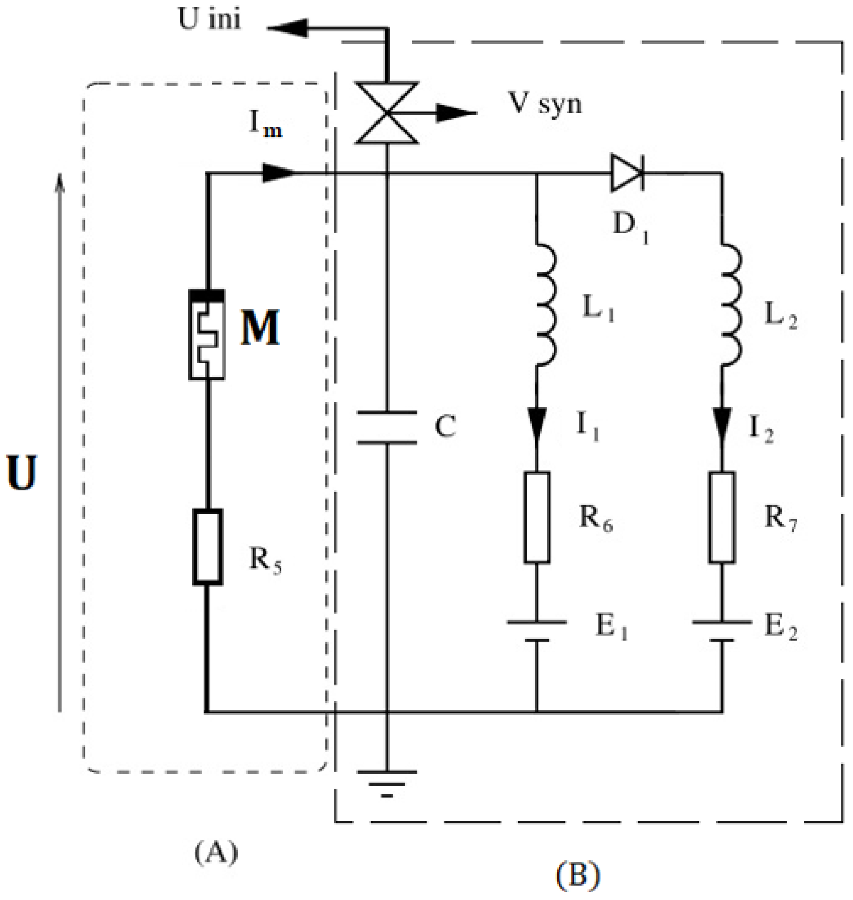
The nonlinear scheme of a memristive generator FHN, as shown in
Figure 1, can be described as follows: part (A) corresponds to memristive nonlinearity. In this figure,
U is the voltage and
Im is the corresponding current. Part (B) consists of linear resistors R
6, R
7, linear inductors L
1, L
2, and linear capacitance C in parallel with them, as well as power supplies E
1, E
2, and a commuted silicon diode D
1. The initial condition
Vini can be loaded into the neuron via an analog switch controlled by a periodic
Vsyn signal.
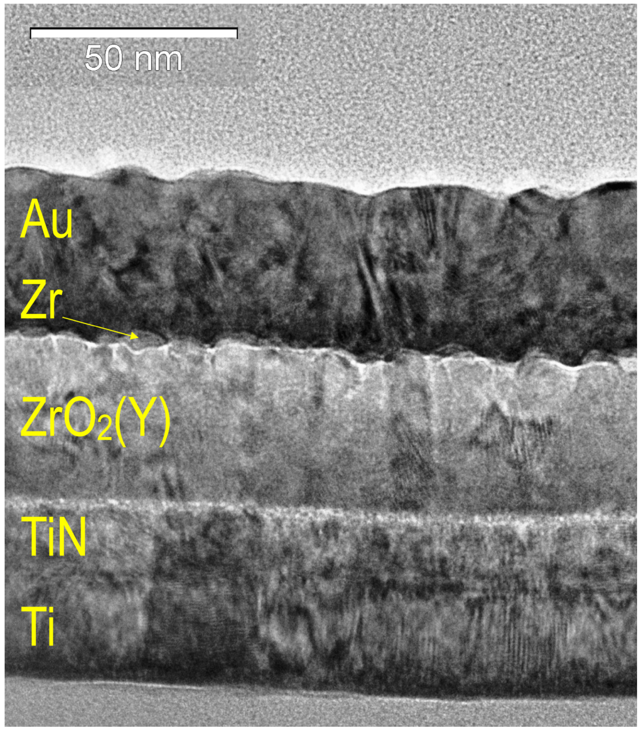
Here, the nonlinear element is presented by the Au/Zr/ZrO
2(Y)/TiN/Ti memristor fabricated on the oxidized silicon substrate using magnetron sputtering. The details of technological operations can be found in other works [
3,
13,
16,
35,
36,
37]. To study the structure of the element, we used the high-resolution cross-sectional transmission electron microscopy (XTEM) operating the Jeol JEM-2100F microscope («JEOL» company, Japan) with an acceleration voltage of 200 kV. The cross sections of memristive devices were prepared by conventional technology using the equipment of Gatan Inc. We also developed a custom topology to fabricate the array of paired micro-scale (20 × 20 μm
2) cross-point memristive devices (overall 44 devices) with the described thin-film structure on a silicon chip and mounted the chip in a standard 64-pin package. Electrical measurements and electroforming were carried out at room temperature by using the Agilent B1500A semiconductor device analyzer («ASTANA» company, Russia). Such chips containing several memristive devices are necessary for further studies of complex nonlinear effects in ensembles of oscillators.
Figure 2 shows the result of the cross-sectional transmission electron microscopy (TEM) of the Au/Zr/ZrO
2(Y)/TiN/Ti memristor.
After electroforming at negative bias, the memristive device demonstrated bipolar resistive switching with a resistance window between the high-resistance (HRS) and low-resistance (LRS) states
RHRS/
RLRS ≈ 10
4 at a reading voltage of
Ur = −0.5 V (
Figure 3). The voltage values when switching the experimental device were
Vset = −5 V and
Vreset = 6 V. Positive voltage induced switching from LRS to HRS (RESET), and negative voltage resulted in switching from HRS to LRS (SET). Devices on this basis show a good characteristic for neuromorphic computing, where constant weights are necessary for accurate training and computations [
13].
2.2. Mathematical Model of a Memristor
The mathematical model of a memristive device used a general definition of a memristor as a dynamical system [
37] and operated with the experimentally determined parameters and mechanisms of electron and ion transport inside the memristive device with a current applied to it.
The equation for the output of the memristive device represents the total electronic current dominating in LRS and HRS, respectively:
As part of a state equation, an internal state variable
x ∈ [0, 1] was introduced. This variable was determined by the fraction of the area of the structure occupied by filaments, the change of which depends on the migration of oxygen vacancies (effective migration barrier
Em = −34.8) [
30], activated by Joule heating (
kT = 4.14
10
−21 Joule) and applied electric voltage
u. The transition between HRS and LRS was determined by the dynamic contribution to the total current of filaments and, consequently, by the state parameter. In these equations
b = 3.2,
B = 2.5
10
21 are the coefficients determined by quadratic polynomial interpolation from experimental data of a physical device.
The total current density jm through the memristive device was determined by the transfer of charge carriers through defect states in the oxide material in the region of the filament rupture or the rest of the structure. Such a structure consists of a linear component jlin, which corresponds to ohmic conductivity ( = 10−8—Coeff for Ohmic current) through filaments (conducting pathways in the memristive structure), and a nonlinear component jnonlin. The nonlinear transfer of charge carriers (effective barrier Eb = 38.6) is described by the Frenkel–Poole law based on the approximation of current–voltage characteristics in HRS.
The dynamics of the variable
x are described by the following equations:
The state equations include a window function
previously introduced by Yu. N. Joglekar and S. J. Wolf [
38]. In this function,
p is a positive integer specifying its shape. It takes a zero value of
x outside the interval (0, 1).
In the above equations α1 = 30.9, A = 109—coefficients corresponding to experimental data. Vset = −3 and Vreset = 3 are the threshold voltages for resistive switching.
The I–V curves of the hysteresis type of this device, obtained as a result of numerical simulation, are shown in
Figure 4. Supplying voltage in the form of a rectangular pulse with values of ±5 V to memristive device (1)–(2) during 2000 ms. The initial state of the storage device was in HRS, then the device switched to LRS. The obtained characteristics correspond qualitatively to the experimental Au/Zr/ZrO
2(Y)/TiN/Ti device.
2.3. Memristive Oscillator Model
To model a neuronal oscillator, we took a modified FHN neuron explored mathematically in [
39] and implemented electronically in [
34]. The model equations are expressed as follows:
where
is the nonlinear function as the product of the memristor current by its load resistance. The current function is the product of the total current density of the memristive structure multiplied by the area of its electrodes
;
is a quasilinear function where
if
and
if
, where
and
;
u is the transmembrane potential (membrane potential) of the FHN neuron; and
v is a “restoring” variable (determines the dynamics of ion current responsible for restoring the equilibrium potential of the neuron cell).
is the control parameter (bifurcation parameter) and
is the recovery parameter. The
parameter controlling the excitability of the modeled neuron is also a normalization parameter. The parameter
is obtained using the least squares method.
Then, we replaced (2) with (3). So that we obtained the following three-dimensional system describing the circuit dynamics:
where the first equation of the system was obtained as follows:
The value of the linear and nonlinear components of the current density from (1) is substituted into the general formula of the current density of the memristive device;
The total current density is substituted into the formula for the current strength of the memristive device ;
The resulting current strength is multiplied by the parameters and d, a nonlinear function is obtained, which is then substituted into the differential Equation (4).
We fixed the following parameter values: , Se = 4 , d = .
2.4. Numerical Investigation Methods
Nonlinear differential Equation (4) was solved numerically using the 4-order Runge–Kutta (RK4). The convergence of this method follows from the theorem: if the numerical method is stable and approximates the initial differential problem and the initial data with the order of accuracy O(h
p), then it converges on the segment (x
0, X] to the solution of the differential problem with the order O(h
p). The full description of the method is given in [
40]. The integration procedure was performed with a step of 0.02 and an error of 10
−6 in the application software package for solving MATLAB version R2020b (The MathWorks, USA, purchased from the official website) technical computing problems [
41,
42,
43]. Choosing the initial conditions, we obtained the following results when changing the control parameter.
To study the transition between excitable and oscillatory dynamical modes, we calculated a one-parameter bifurcation diagram illustrating changes in the oscillation amplitude depending on control parameters. To do this, we ran simulations from two sets of initial conditions, one taken close to the fixed point and the other far from it. After a sufficiently long transient process of 5000 ms, the trajectory of Equation (4) converged to a stationary mode, either the rest state or the state of periodic oscillations.
Then we analyzed how the critical parameter corresponding to oscillation appearance depended on the electrode area in the memristive nonlinearity.
2.5. Experimental Study of the Generator
The developed neuromorphic oscillator consisted of an analog electronic FHN neuron containing a memristive arrangement, a DPO 4054 oscilloscope («TEKTRONIX» company, USA) (
Figure 5a), and an Agilent B1500a device analyzer for obtaining and studying the I–V characteristics of the device (
Figure 5b). This neuromorphic oscillator operates as follows. The analog memristive neuron–like FHN neuron creates a signal in the form of a pulse, thereby affecting the memory device and thus imitating the reduction and oxidation of conductive filaments in the oxide (dielectric) layer of the memristive device.
The developed memristive neuron–like generator consists of two blocks. The first block is an oscillatory generator, or, as it is also called, an R–L generator, based on an operational amplifier-implemented inductance. The second is the block of excitation pulses (block of nonlinearity), which includes a storage device Au/Zr/ZrO
2(Y)/TiN/Ti and a resistor representing a load (
Figure 5c).
In this circuit, the voltage from the 1.5 V power supply is varied by a sequential switching on of an alternating resistor (from 0 to 150 kΩ). From the output point of the generator, the signal comes to the recording device (digital oscilloscope) in the form of an oscillogram.
3. Results
3.1. Memristive Neuron Model Dynamics
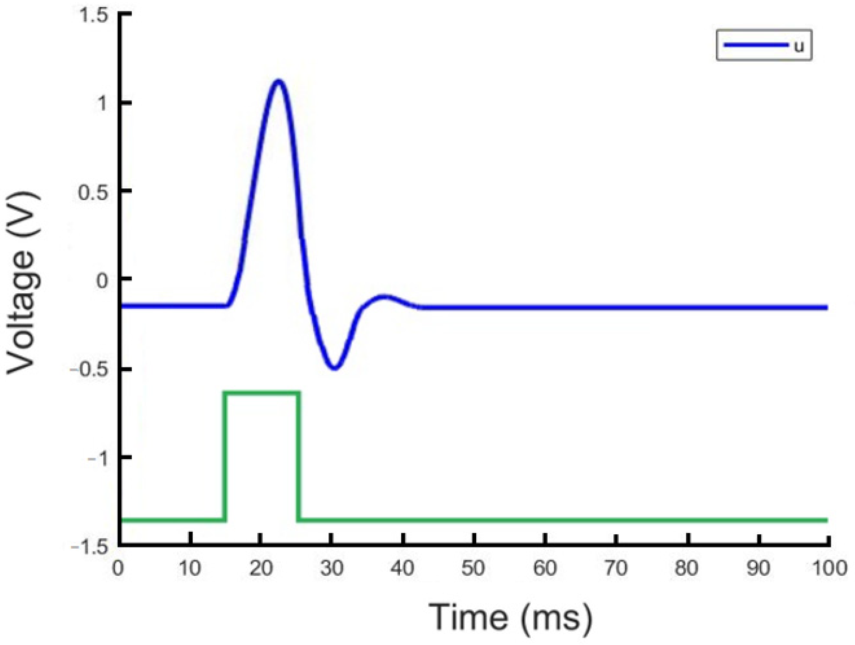
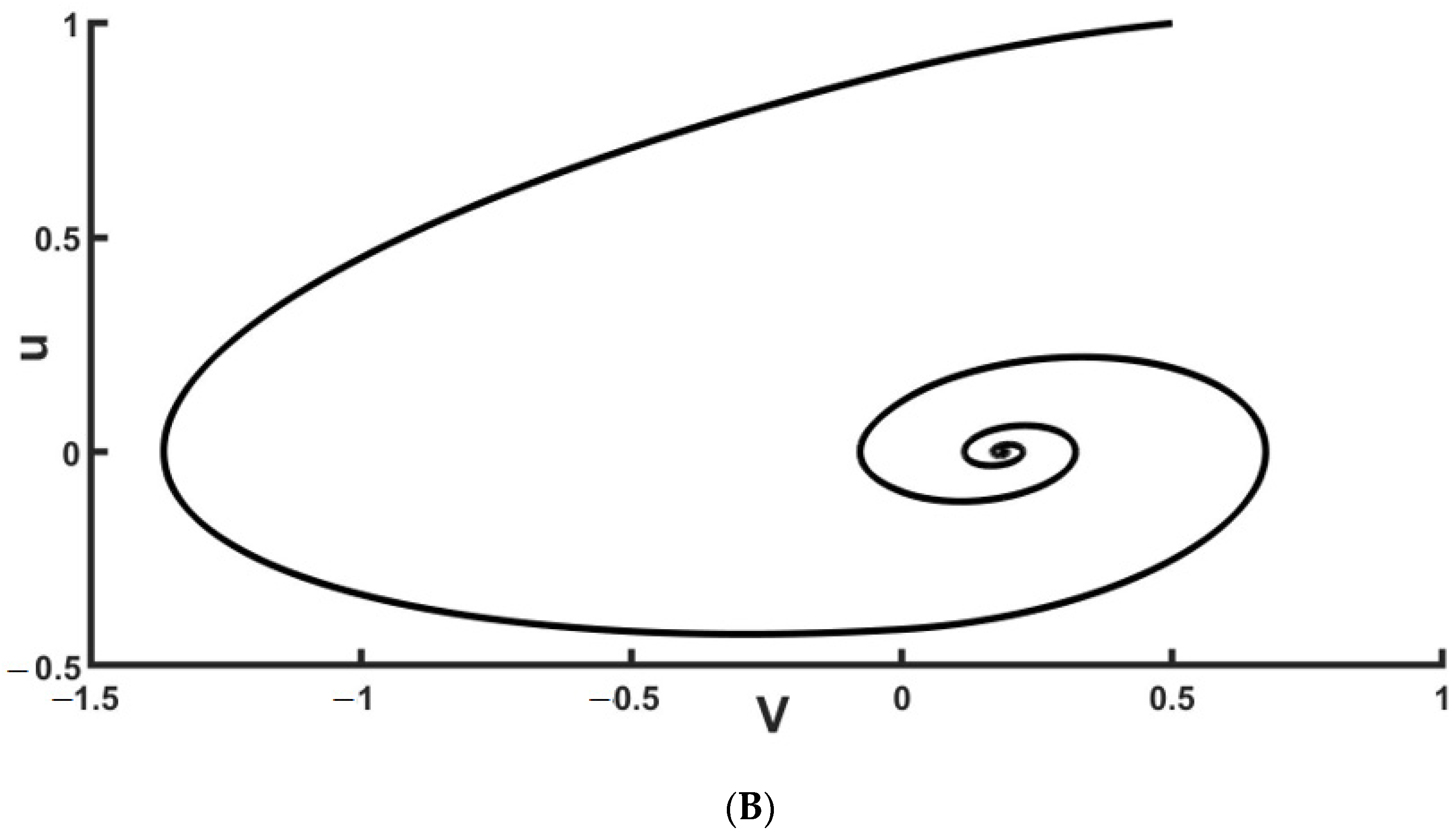
Numerical exploration of a 3D nonlinear dynamical system (4) reveals the existence of excitable and oscillatory dynamical modes. In the excitable mode, the model similar to living neurons possesses a stable fixed point of a node or focus type. For relatively small perturbations the trajectories converge to the vicinity of the stable point. However, for large enough perturbation, we obtained a response pulse of sufficiently high amplitude (
Figure 6).
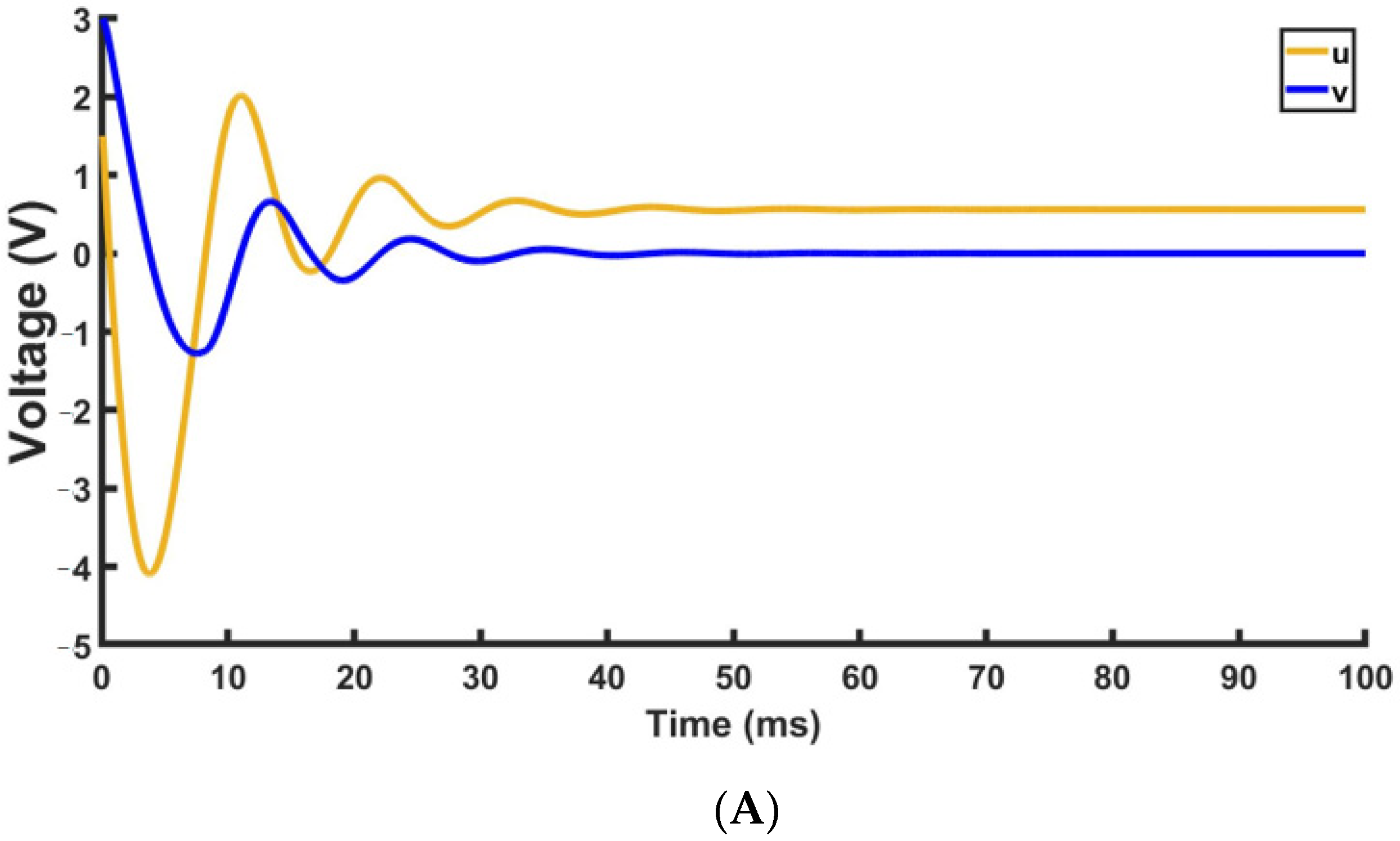
Analyzing system dynamics in the neighborhood of the stable fixed point, we find its focus type corresponding to damped oscillation (ε = 0.0003–0.89, see
Figure 7).
The numerically calculated characteristics of the damped oscillations are presented in
Table 1.
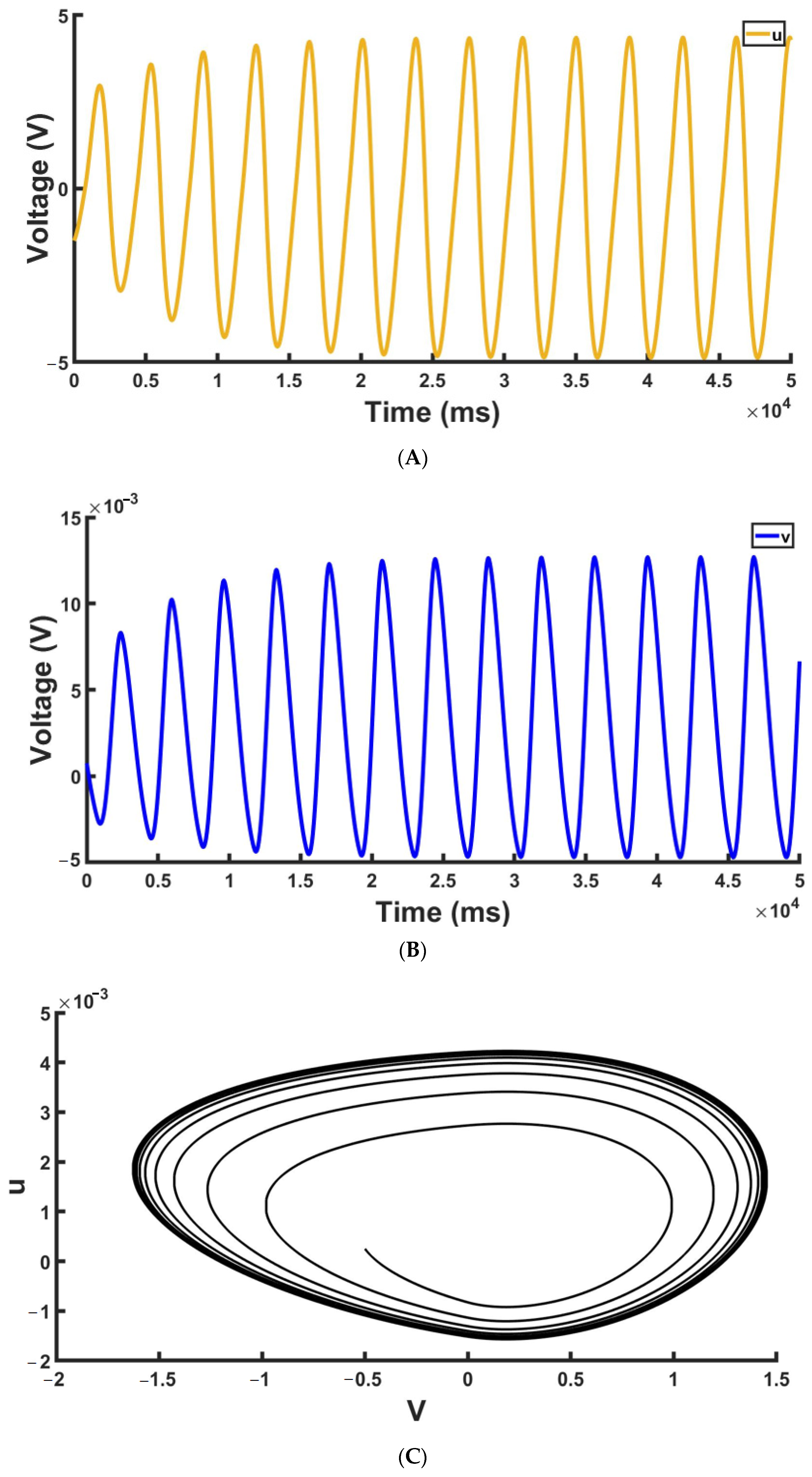
With decreasing
, the real part of the fixed–point eigenvalues tends to decrease followed by increasing transient in the damped oscillation. With the further decrease of the parameter, we end up with periodic generation mode (ε = 0.00041–0.000003, see
Figure 8).
The numerically calculated characteristics of the periodic generation mode oscillations are presented in
Table 2.
A stable limit cycle appears in the phase space corresponding to the periodic generation of neuronal oscillations. Following the numerical simulations, it is likely to correspond to a supercritical Andronov–Hopf bifurcation with a negative first Lyapunov value. In the next subsection, we will go into more detail about the bifurcation scenario.
Thus, our model qualitatively demonstrates the key characteristics of the dynamics of neurons, including excitability and oscillatory dynamics.
3.2. Bifurcation Analysis
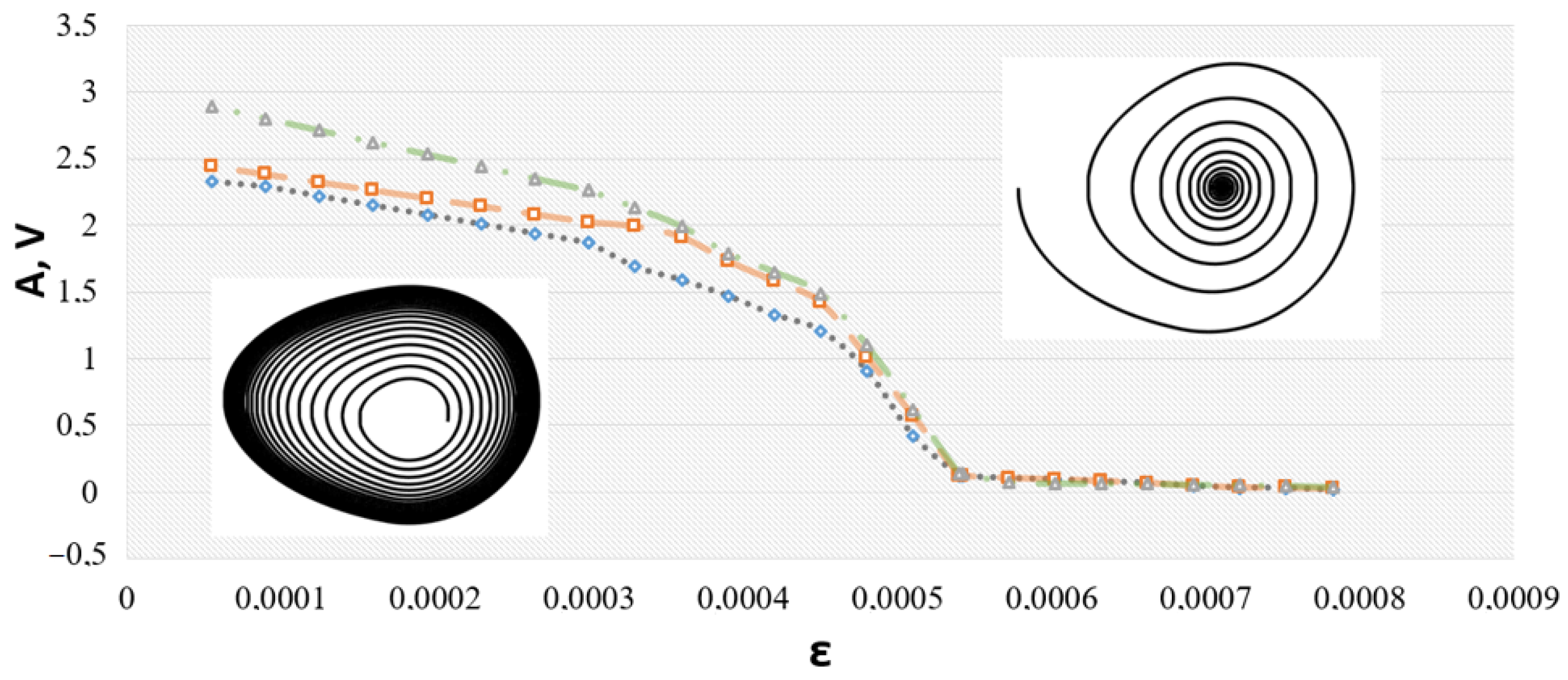
In the bifurcation analysis, we fixed all parameters except for and started by calculating the one-parameter bifurcation diagram for the fixed electrode area 50 × 50 μm2 of the memristive device. To detect possible subcritical modes or other attractors, we ran simulations for three different sets of initial conditions, [u(t = 0), v(t = 0), x(t = 0)], with the following values: y1 = [0.5, 0.25, 0.2], y2 = [−0.5, 0.004, 0.1], y3 = [2, 1, 0.5]. Transient time, e.g., estimation time of the transient process, was varied in the interval 100 ms < t < 50,000 ms with integration step h = 0.02. Next, the amplitude per cycle was calculated as the difference between the maximum and minimum cycle values for one period.
Figure 9 shows the dependence of the amplitude on parameter ε, and corresponding projections of phase trajectories on the (
u,
v) plane. Different curves correspond to different initial conditions. A critical parameter
corresponds to the appearance of the non-zero oscillation amplitude.
At this point, the stable fixed point-of-focus type loses its stability and the stable limit cycle appears to the left of the critical point. The vicinity of critical ε corresponds to the neutral stability of the fixed point, and the limit cycle appears from the bifurcation alone, as illustrated in the phase portraits. In other words, the transient processes last for a longer time as they get closer to the bifurcation point. That is, trajectories from different initial conditions for fixed calculation time end up at slightly different amplitude values, as illustrated in
Figure 8. Therefore, numerical simulations eventually illustrate that Andronov–Hopf bifurcation, in its supercritical mode, takes place in Equation (4).
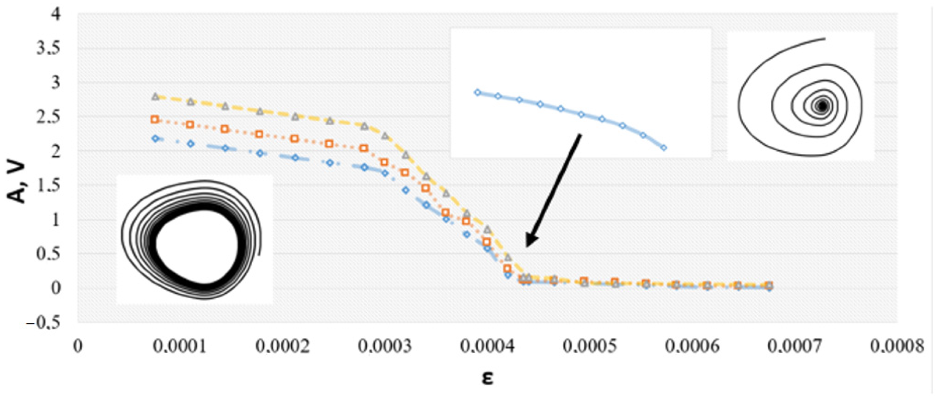
Next, we analyzed how the value of the bifurcation parameter
depends on the electrode area of the memristor. Typical values used in fabrication include the following: 5 × 5, 10 × 10, 15 × 15, 20 × 20, 25 × 25 μm
2.
Figure 10 illustrates the bifurcation diagram for the smallest device size. It is quite similar to the previous case, but the critical
is shifted to a higher voltage.
This model does not belong to type I or type II models of a neuron. It does not have a saddle point with a well-defined firing threshold and the corresponding node–saddle bifurcation into the limit cycle, as in type I neuron models. And of course, it does not have a coexisting point attractor and the limit cycle, as in type II neurons.
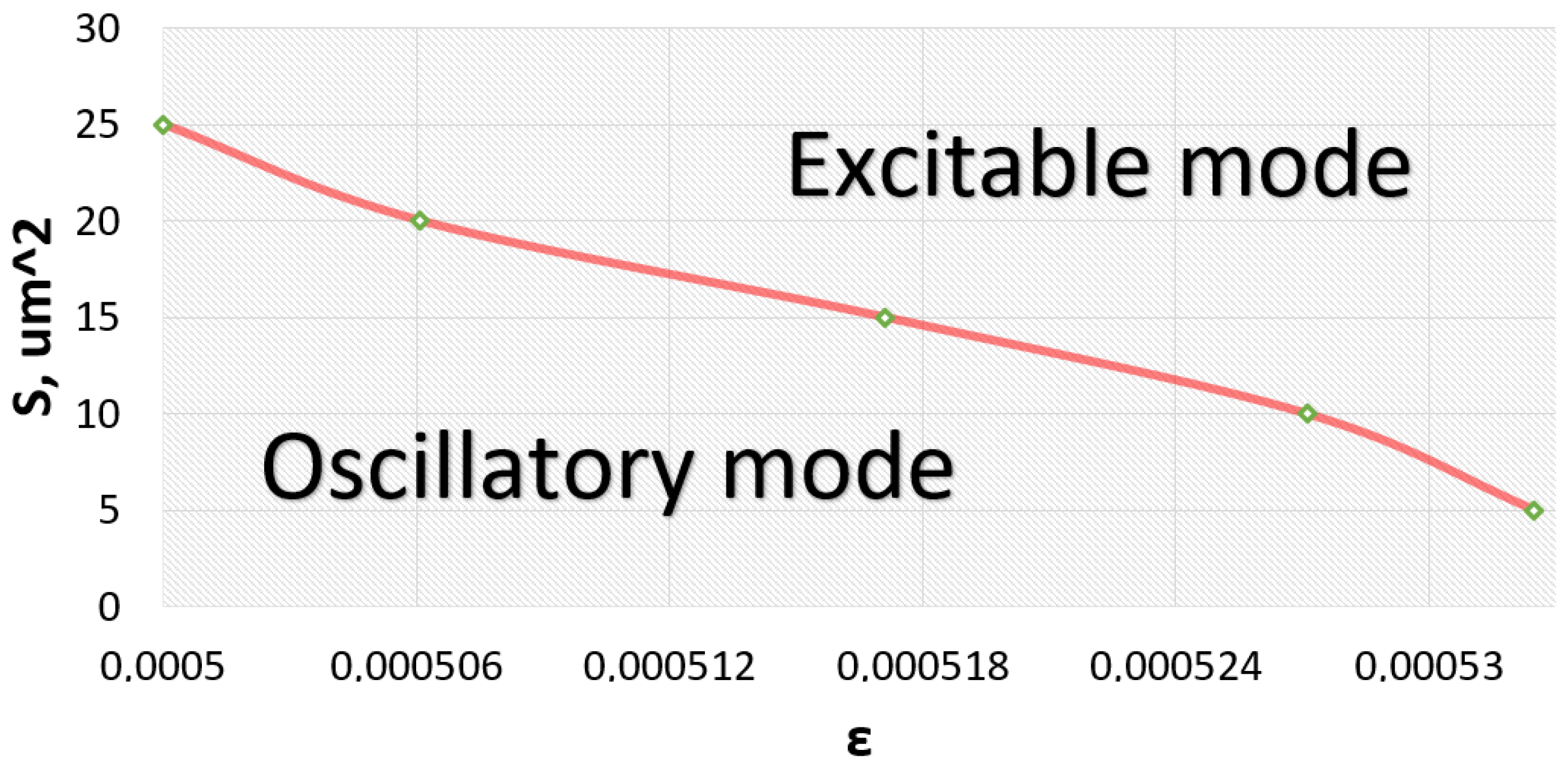
Finally, we analyzed how the critical bifurcation parameter
depends on the electrode area for all possible sizes. In the two–parameter bifurcation diagram shown in
Figure 11, one can note a nonlinear curve in the (
plane, delineating regions of excitable and oscillatory dynamics.
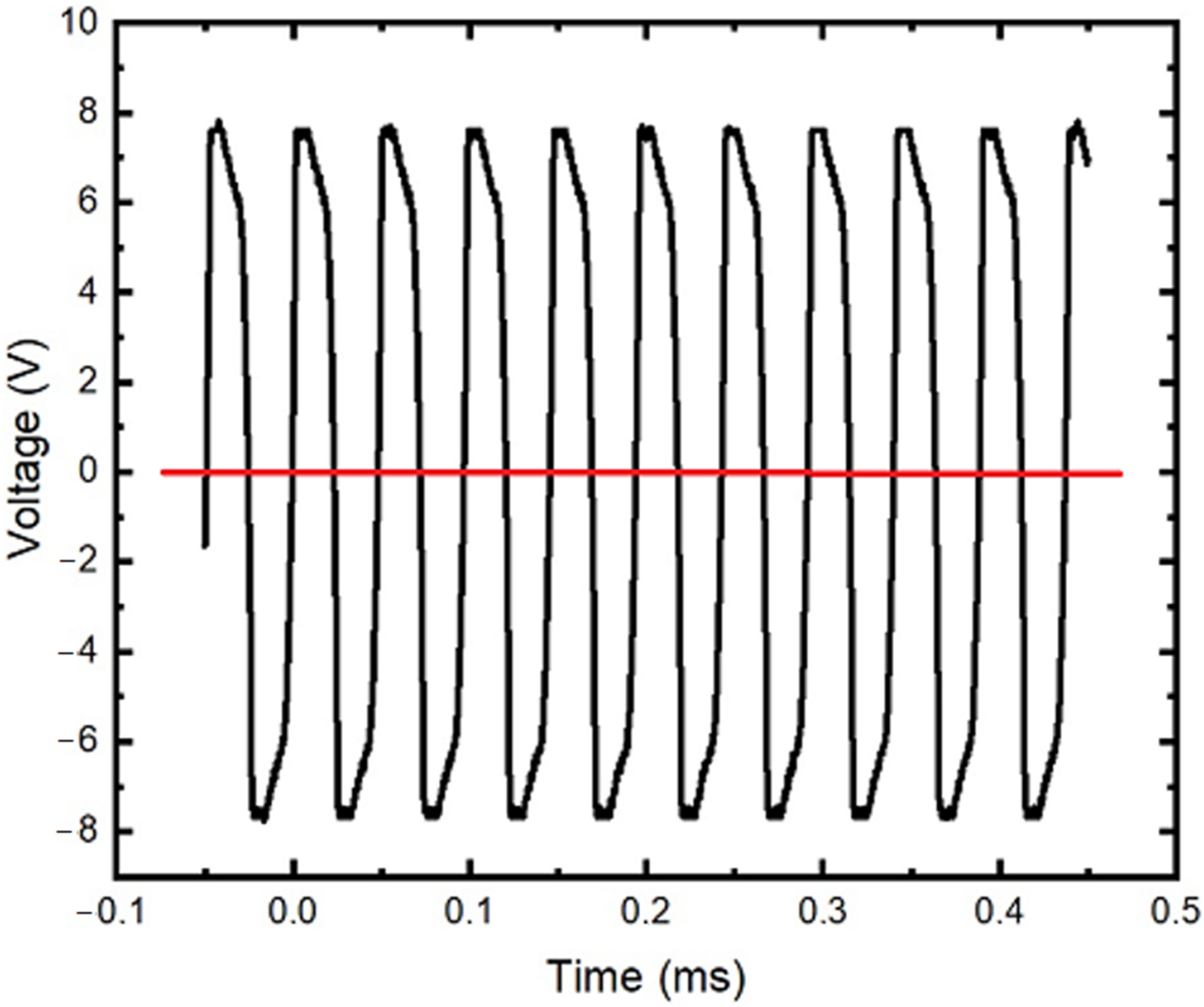
3.3. Memristive Neural Dynamics Generation
After inspection and regulation, the generator, a memristive device, was connected to the nonlinearity block. This generator demonstrates both the self–oscillating mode and the excitable modes (
Figure 12).
The signal shown in
Figure 12 (black line) was fed to the storage device which was subsequently switched from HRS to LRS (
Figure 3).
The intended switching process is related to the local heating along the current path that activates the processes of migration of oxygen ions and determines the switching threshold (as in the case of a dielectric breakdown) [
44]. In the SET process (growth of filaments), oxygen ions migrate to the TiN layer (the reduction of oxide). In the RESET process, they return to oxidizing the filaments [
30].
Time series and I–V characteristics obtained numerically and experimentally have differences, however the experiment confirms the resistive switching of our device predicted by the model. Additionally, our system describes the dynamics close to the experimentally observed one, in contrast to the first-order memristor model, taking into account the stochasticity of switching. The submitted work is fundamental to the integration of such devices into a neuron-like FHN generator, both numerically and experimentally.
4. Conclusions
We have investigated a novel mathematical and experimental model of a neuronal oscillator comprising the modified Fitzhugh–Nagumo neural generator [
27] with nonlinearity based on the Au/Zr/ZrO
2(Y)/TiN/Ti memristor. Bipolar resistive switching cycles demonstrated the stable operation and a resistance ratio of
RHRS/
RLRS ≈ 10
4 at a reading voltage of
Ur = −0.5 V. The I–V curve of a memristive device was modeled when ±5 V was applied to the device for 2000 ms. This characteristic qualitatively corresponds to the real structure of Au/Zr/ZrO
2(Y)/TiN/Ti.
For an electronic circuit with memristive nonlinearity, we obtained a three-dimensional nonlinear ordinary differential equation system. Exploring this system in the numerical simulation we analyzed its two basic dynamical modes of excitable neuron-like dynamics and quasi-harmonic self–oscillations. We found and numerically illustrated the Andronov–Hopf bifurcation as the basic bifurcation scenario of the oscillation appearance. The dependence of the bifurcation parameter points on the memristive device electrode area size were analyzed.
Stochastic switching of the storage device from a state with high resistance to a state with low resistance was achieved due to the signal supplied from the generator to the device. This enables both the self-oscillating and the excitable modes of generation.
As a discussion point, along with many other similar studies in this field, we constructed a memristor-based model of a neuronal oscillator. One of its advantages is the specific nonlinearity determined experimentally for the fabricated Au/Zr/ZrO
2(Y)/TiN/Ti memristor. The other is that the original circuit of the modified FitzHugh–Nagumo neuron used in simulations is known to demonstrate computation by spikes with both integrate–and–fire and resonant–and–fire communication modes [
39].
Therefore, we believe that, in further investigations, our model of the memristor-based neuronal oscillator will be a potential candidate for use in neuromorphic computing based on spike communication.


 ,
, 


