Abstract
The study of position control for variable stiffness actuators is important for improving their energy efficiency and robustness. In this paper, for the previously proposed nonlinear variable stiffness actuator, firstly, a dynamic model of the variable stiffness actuator system is established based on a two-inertia-system theory. Secondly, the effects of friction and gravity factors on the dynamic performance of the system are analyzed. The results of the study show that friction and gravity have obvious effects on the dynamic characteristics of the system in the constant stiffness state, and that these effects are more complex and obvious in the variable stiffness state, which proves the reasonableness and necessity of considering friction and gravity in the dynamics modeling process. Then, in order to improve the dynamic performance of the system and make its positioning performance meet the requirements, the control strategy of the variable stiffness actuator system is studied. The results show that the sliding mode control strategy based on nonlinear disturbance observer and dynamics model is a good solution to the effect of friction and gravity on the system, and can make its position-tracking performance meet the requirements. Finally, the correctness and effectiveness of the control strategy are verified experimentally.
Keywords:
variable stiffness actuator; two-inertia-system; dynamic performance; friction; gravity; position control MSC:
93-11
1. Introduction
Highly-sophisticated mobile measurement robots, legged mobile robots, and exoskeleton-assisted robots seek precise and efficient motion and high levels of safety during human-robot interactions. The application of variable stiffness actuators not only improves safety and flexibility, but also contributes to the energy efficiency of the robotic system, and makes the robotic system more robust to disturbances and un-modeled dynamics [1,2,3]. However, this still cannot avoid nonlinear problems caused by the backlash, hysteresis, deadband and stiffness adjustment, all of which can reduce the control accuracy or even lead to oscillation or instability of the system [4]. Therefore, in order to solve these problems, it is necessary to conduct an in-depth study of the dynamic performance and position control of variable stiffness actuators.
For variable stiffness actuators, the introduction of the stiffness motor system can reduce the control bandwidth of the position motor system. In addition, the friction and rotational inertia of the stiffness motor system can also produce noise disturbance to the position motor system, so it is a complex nonlinear coupling disturbance [5]. Although there are many control strategies for nonlinear systems, proportion integration differentiation (PID) control and its derived control strategies are still used in a large number of studies due to their relative simplicity; for example: The RVSA designed by Xu et al. [6], the AMASC designed by Hurst et al. [7], the variable stiffness actuator designed by Yang et al. [8], the VSA and VSA-II designed by Tonietti and Schiavi et al. [9,10], the NSA designed by Hu et al. [11], and the variable stiffness actuator designed by Liu et al. [12] all used a general proportion differentiation (PD) control strategy for position tracking control of position motor systems and stiffness motor systems. Jafari et al. used PD and additional differential control strategies for AwAS-I and AwAS-II to suppress the linkage side oscillations caused by the coupling disturbance in low stiffness states [13,14]. Zhai et al. designed an active control strategy based on a fuzzy PID algorithm in order to dynamically adjust the stiffness and damping of the system [15]. Sun et al. used feedforward and feedback PD control strategies to control the position motor system and the stiffness motor system in the prototype validation of both SVSA-I and SVSA-II [16,17].
Although the PID control studied above has a certain suppression effect on the coupling disturbance, the effectiveness of the PID controller is severely reduced when the stiffness of the actuator changes. Therefore, the PID control is mainly used in the initial scheme of the variable stiffness actuator, and the researchers can propose new control strategies for the designed variable stiffness actuator in subsequent studies. Jimenez-Fabian et al. used gradient descent optimal control for real-time control of the stiffness and position control of the MACCEPA to achieve a balance between accurate position tracking and minimum energy consumption [18]. Palli et al. linearized the nonlinear coupling disturbance of the variable stiffness actuator to achieve full-state feedback control [19]. Sardellitti et al. designed a gain scheduling controller based on linear quadratic regulator for AwAS to solve the problems of optimal control, feedback linearization and other control gain fixation [20]. Liu et al. designed a cascaded gain scheduling controller based on linear quadratic Gaussian analysis for the mechanical-rotary variable impedance actuator [21]. Such model-based control requires high modeling accuracy and precise parameter identification, while the disturbance observer can reduce the dependence of control on modeling accuracy [22]. On the other hand, most of the control strategies based on disturbance observation techniques are concentrated on series elastic actuators with constant stiffness, and relatively little research has been performed upon variable stiffness actuators [23,24,25,26,27]. In addition, due to the presence of the variable stiffness mechanism, the stiffness motor system and the position motor system are bound to have couplings of different degrees, especially when the stiffness is small. In these cases, the disturbances of the system are mainly caused by uncertainties such as friction, backlash, hysteresis loops, and dead zones, and its nonlinearity is more serious and difficult to model and analyze [28,29]. These factors can affect the position tracking performance of the position motor system and reduce the robustness of the system, while the position control accuracy of the output axis of the variable stiffness actuator affects the overall quality of the completed task.
For the dynamic modeling of the variable stiffness actuator, most of the studies focus on the load side, and the motor is considered to be used only to apply force or displacement to the system, so the compliance of the connection between the motor and the load is neglected. However, for variable stiffness actuators, the stiffness of the actuator is changed by changing the displacement deformation of the elastic element; therefore, the compliance of the connection between the motor and the load and the inertia characteristics of the motor should not be ignored. In addition, there are many studies for two-inertia-systems, but they mainly consider the compliance of the connection between the actuator and the external load, which is also due to the fact that they mainly use common actuators [30,31,32,33,34]. Therefore, in this paper, the two-inertia-system theory is introduced into the study of the variable stiffness actuator to improve the accuracy of the dynamic modeling and the control accuracy of the variable stiffness actuator.
Therefore, in this paper, for a previously designed variable stiffness actuator [8,35], firstly, a two-inertia-system dynamic model of the variable stiffness actuator is developed; secondly, the effects of friction and gravity on the dynamic performance of the system are analyzed by the established two-inertia-system model, and then the control strategy of the variable stiffness actuator system is studied to improve the dynamic performance of the system and to make its position tracking performance meet the requirements of use. Finally, the effectiveness and correctness of the control strategy are verified by experiment.
The rest of the paper is organized as follows. In Section 2, based on the two-inertia-system theory, a two-inertia-system dynamics model of the variable stiffness actuator considering friction and gravity is developed; In Section 3, the effects of friction and gravity on the dynamic performance of the variable stiffness actuator system are analyzed; In Section 4, the control strategy of the variable stiffness actuator system is studied; In Section 5, the conclusion is stated.
2. Two-Inertia-System Dynamics Model of a Variable Stiffness Actuator
A previously designed leg prototype containing the variable stiffness actuator is shown in Figure 1. The two-inertia-system dynamics model of the designed variable stiffness actuator can also be seen in Figure 1, which consists of a position motor system and a stiffness motor system in parallel. The position motor and the stiffness motor are connected with the spindle through the drive shaft system and the coupling, which have certain torsional stiffness and damping by themselves. Therefore, when the dynamic model is established, the two-inertia-system theory is used for modeling, and the viscous friction, uncertain external input and other disturbances of the two drive chains should also be considered in the modeling.
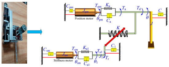
Figure 1.
The schematic diagram of the two-inertia-system dynamics model of the variable stiffness actuator.
J, J1, Jpm and Jsm are rotational inertias of the lower leg, ball screw, position motor system, and stiffness motor system, respectively; C, C1, Cpm and Csm are damping coefficients of the lower leg, ball screw, position motor and stiffness motor, respectively; θ, θ1, θpm and θsm are rotation angles of the lower leg, ball screw, position motor, and stiffness motor, respectively; Tpm and Tsm are input torques of the position motor and the stiffness motor, respectively; Ka and Ka1 are torsional stiffness of the drive system of the position motor system and the stiffness motor system, respectively; Ca and Ca1 are damping coefficients of the drive system of the position motor system and the stiffness motor system, respectively; Ta and Ta1 are input torques of the lower leg and the ball screw, respectively; Td and Tr are total disturbances of the position motor system and the stiffness motor system, respectively; K is the stiffness of the variable stiffness actuator, as shown in Equation (2).
According to Figure 1 and the Lagrange formula [36,37], the dynamics model of the system is shown in Equation (1).
where Tvs is the elastic torque due to the variable stiffness system; m is the mass of the lower leg; L1 is the distance between the center of mass of the lower leg and the axis; and g is the acceleration of gravity.
where E is the Young’s modulus of the cantilever beam; I is the inertia moment of the cantilever beam, which can be obtained from the geometric parameters of the cantilever beam, e is the eccentric distance of the eccentric cam; rt is the radius of the roller; r is the distance between the center of the roller and the axle center of the eccentric cam; h is the maximum travel distance of the push rod; and θ0 is the rotation angles of the eccentric cam at the maximum extending stroke.
As for the total disturbance Td of the system, it consists of two main parts: one is the disturbance moment Tdd outside the variable stiffness actuator and the other is the friction moment Tf1 inside the system, which can be described by the LuGre friction model [38] as shown in Equation (3).
where δ0 is the friction stiffness coefficient of the system; δ1 is the friction damping coefficient of the system; δ2 is the viscous friction coefficient of the system; z11 is the internal friction state of the system; Tc1 is the Coulomb friction moment of the system; Ts1 is the static friction moment of the system; and is the Stribeck velocity of the system.
3. Dynamic Performance Analysis of a Variable Stiffness Actuator System
The dynamic performance of the variable stiffness actuator system and the effect of friction and gravity on its dynamic performance can be derived by analyzing Equation (1) with the 4th order Runge-Kutta algorithm; in the analysis process, a fixed step is chosen as 10−6. During the analysis, in order to analyze the effects of friction and gravity on the dynamic performance of the variable stiffness actuator system, the dynamic performance of the system was studied at two states: constant stiffness and variable stiffness, respectively. In addition, the input torque of the position motor Tpm = 25sin(2πt) Nm is chosen and the specific simulation parameters of the variable stiffness actuator system are shown in Table 1.

Table 1.
Specific simulation parameters of the variable stiffness actuator system.
3.1. The Effect of Friction on the Dynamic Performance of the Variable Stiffness Actuator System at Constant Stiffness Condition
Assuming that the stiffness of the variable stiffness actuator remains constant at 100 Nm/rad during the motion, the effect of friction on the dynamic performance of the variable stiffness actuator system in this state is analyzed, and the results are shown in Figure 2.
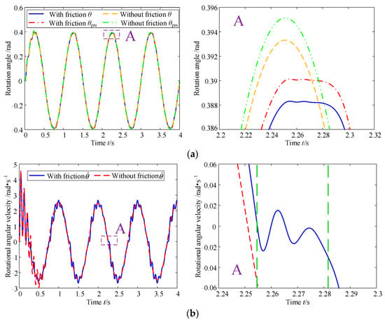
Figure 2.
Effect of friction on the dynamic performance of the variable stiffness actuator system at constant stiffness: (a) rotation angle and (b) rotational angular velocity.
As can be seen in Figure 2, after considering friction, firstly, the amplitude of both the rotation angle θpm of the position motor and the rotation angle θ of the load are reduced, and the time to reach the maximum value is delayed, which is caused by the friction’s consuming part of the energy of the position motor system. Secondly, after considering the friction, there is a period of stability at the maximum value of θpm and θ, which is due to the friction that causes a certain hysteresis when the position motor or the load changes the direction of motion, this is more evident in the rotational angular velocity in Figure 2b (the rotational angular velocity of the load first fluctuates for a short time around 0, and then continues to move according to the established pattern). Then, it can also be seen from Figure 2a that the rotation angle θpm of the position motor and the rotation angle θ of the load show a certain difference regardless of whether the friction is considered or not, which can be explained by considering the flexibility of the coupling and the transmission system; this also proves that it is necessary to model the dynamics of the position motor system using the double inertia theory, otherwise the analysis can cause certain errors in practical application. In addition, it can be seen from Figure 2b that when friction is considered, the rotational angular velocity of the load appears to crawl, which greatly reduces the dynamic performance of the system.
3.2. The Effect of Gravity on Dynamic Performance of Variable Stiffness Actuator System at Constant Stiffness Condition
Assuming that the stiffness of the variable stiffness actuator remains constant at 100 Nm/rad during the motion, the effect of gravity on the dynamic performance of the variable stiffness actuator system in this state is analyzed, and the results are shown in Figure 3.
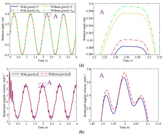
Figure 3.
Effect of gravity on the dynamic performance of the variable stiffness actuator system at constant stiffness: (a) rotation angle and (b) rotational angular velocity.
As can be seen in Figure 3, firstly, both the rotation angle θpm of the position motor and the rotation angle θ of the load at the same torque are reduced after considering gravity, because a part of the torque provided by the position motor is offset by the gravity of the load, and therefore the torque provided to the load and the position motor is reduced. Secondly, when gravity is not considered, the rotational angular velocity of the load is greater than the rotational angular velocity with gravity for the same reason. In addition, it can be seen from Figure 3a,b that the hysteresis due to friction is reduced by gravity.
3.3. The Effect of Friction on Dynamic Performance of Variable Stiffness Actuator System at Variable Stiffness Condition
Assuming that the stiffness of the variable stiffness actuator has been changing with the law of 50 × sin(2πt) + 100 Nm/rad during the motion, the effect of friction on the dynamic performance of the variable stiffness actuator system in this state is analyzed, and the specific results are shown in Figure 4.
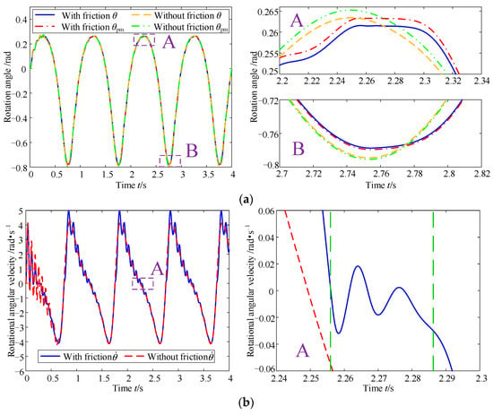
Figure 4.
Effect of friction on the dynamic performance of position motor systems at variable stiffness: (a) rotation angle and (b) rotational angular velocity.
As can be seen in Figure 4, compared with Figure 2a, since the stiffness of the first half-period of each period at a variable stiffness condition is larger than the stiffness at constant stiffness condition, both the rotation angle θpm of the position motor and the rotation angle θ of the load in the variable stiffness condition are much smaller; while the stiffness of the second half-period in the variable stiffness condition is smaller than the stiffness at constant stiffness condition. Therefore, both the rotation angle θpm of the position motor and the rotation angle θ of the load at variable stiffness condition are much larger. Then, comparing the enlarged figure A of Figure 4a and Figure 2a, it can be seen that the effect of friction on the rotation angle amplitude decreases, but it makes the friction-induced hysteresis phenomenon more obvious, which can also be seen from the comparison of the rotational angle velocity in the enlarged figure A of Figure 4b and Figure 2b. When the stiffness at the variable stiffness condition is smaller than the stiffness at the constant stiffness condition, the effect of friction on the rotation angle can increase, while the hysteresis caused by friction can be reduced, because the greater the stiffness of the system, the more stable the system is, and the smaller is the amplitude of the fluctuation of its rotation angle, and the energy consumed by the friction can thereby be reduced. Finally, it can also be seen from Figure 4b that when the stiffness rises, the fluctuation of the rotational angular velocity of the load is much smaller, because the position motor system is more and more stable when the stiffness rises, while the stability of the system starts to decrease when the stiffness starts to decrease.
3.4. The Effect of Gravity on the Dynamic Performance of the Variable Stiffness Actuator System at Variable Stiffness Condition
Assuming that the stiffness of the variable stiffness actuator has been changing with the law of 50 × sin(2πt) + 100 Nm/rad during the motion, the effect of gravity on the dynamic performance of the variable stiffness actuator system in this state is analyzed, and the specific results are shown in Figure 5.
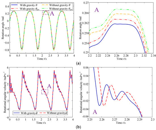
Figure 5.
Effect of gravity on the dynamic performance of position motor systems at variable stiffness: (a) rotation angle and (b) rotational angular velocity.
As can be seen in Figure 5, firstly, since the stiffness of the first half-period of each period at variable stiffness condition is larger than the stiffness at the constant stiffness condition, it can still be seen that both the rotation angle θpm of the position motor and the rotation angle θ of the load are much smaller than in Figure 3a. Since the stiffness of the second half-period is smaller at variable stiffness condition than the stiffness at constant stiffness condition, both the rotation angle θpm of the position motor and the rotation angle θ of the load are much larger than Figure 3a. Then, comparing the enlarged figure A of Figure 5a with the enlarged figure A of Figure 3a, it can be seen that the effect of gravity on the position motor system is reduced at the high stiffness point of the variable stiffness condition. In addition, it can be seen from Figure 5b that the hysteresis effect of friction on the position motor system becomes more pronounced when gravity is not considered.
The above four subsections show that friction and gravity have obvious effects on the dynamic performance of the variable stiffness actuator system at both the constant and variable stiffness conditions, and these effects are more complex and obvious in the variable stiffness state, which proves the reasonableness and necessity of considering friction and gravity in the dynamics modeling process, which lays the foundation for the subsequent research on the accurate control of the variable stiffness actuator.
4. Position Control Strategy for Variable Stiffness Actuator System
From the study in Section 3, it can be seen that the dynamic performance of the variable stiffness actuator system deteriorates when the effects of friction and gravity on the variable stiffness actuator are considered, which is incompatible with the high safety levels required during human-robot interactions. Therefore, this section investigates the control strategy of the variable stiffness actuator system based on the dynamic model, so that the load (lower leg) can have accurate motion capability and minimize or even eliminate the influence of friction and gravity on the variable stiffness actuator.
4.1. The Exponentially Convergent Nonlinear Disturbance Observer Based on Linear Matrix Inequality
From Section 2, the total disturbance Td of the variable stiffness actuator system mainly consists of two parts, one is the disturbance moment Tdd outside the system and the other is the friction moment Tf1 inside the system; the presence of the disturbance Td can seriously degrade the position tracking performance of the variable stiffness actuator system. Therefore, it is necessary to estimate the nonlinear coupling of the variable stiffness actuator system and compensate for it to make the system more stable.
Referring to the two-inertia-system model of the variable stiffness actuator system in Figure 1 and the dynamic model of the system in Equation (1), the dynamics equation of the load side of the system can be written as shown in Equation (4).
Many disturbance observers have been proposed based on the assumption that acceleration measurements of the controlled target are available [39]. Such disturbance observers are required to perform acceleration measurements, but many robotic systems do not have accurate acceleration sensors. Unless robust differentiation techniques are used, differentiation of the velocity signal corrupted by noise is not a suitable choice for deriving acceleration signals [40].
For a common disturbance observer, the form is generally as shown in Equation (5).
Here, a parameter z1 is introduced and is specified as shown in Equation (6).
where p1 can be determined from the corrected observer gain matrix L1 as shown in Equation (7).
Derive Equation (6) and substitute Equations (4), (5), and (7) into it, as shown in Equation (8).
Since the item is eliminated, the improved disturbance observer does not need to measure the acceleration, and its form is shown in Equation (9).
While, referring to the literature [41], the modified observer gain matrix L1 is prescribed as shown in Equation (10).
where X is an invertible constant matrix. Note that the chosen inertia matrix J is generally a symmetric and positive definite value, so the inertia matrix J is invertible.
According to Equations (7) and (10), Equation (11) can be obtained.
The invertible constant matrix X in Equations (10) and (11) can be found by linear matrix inequality. Furthermore, since the differential of the general disturbance Td is not known as a priori knowledge, it is assumed that the disturbance Td changes slowly, relative to the dynamic properties of the observer, i.e., take = 0.
Next, the robustness of exponentially convergent nonlinear disturbance observer based on linear matrix inequality is analyzed. First, the Lyapunov function is designed, as shown in Equation (12).
Since J is both symmetric and positive definite, and the constant matrix X is invertible, the matrix XTJX is also positive definite. Therefore, the scalar function VL1 is also positive definite and radially unbounded. When = 0, the time derivative of VL1 is taken, and the result is shown in Equation (13).
While according to Equation (9), it is known that:
Since = 0, the observation error equation can be obtained as shown in Equation (15).
So,
Substituting Equation (16) into Equation (13) yields the result as in Equation (17).
Here, assume that there exists a positive definite symmetric matrix , which can be conditioned as shown in Equation (18).
Therefore, the combined Equations (17) and (18) can be rewritten as Equation (19).
The analysis of Equation (19) shows that all ΔTd are negative definite, and therefore, this interference observer is showing exponential convergence and the convergence accuracy is dependent on the matrix . The larger the value of , the faster its convergence and the higher the accuracy.
4.2. Nonlinear Sliding Mode Control Strategy Based on Dynamics Model and Disturbance Observer
Assuming that the ideal rotation angle of the load is θd, the tracking error of the variable stiffness actuator system is shown in Equation (20).
The sliding mode function of the variable stiffness actuator system s1 is shown in Equation (21).
In addition, defining the filtering error of the variable stiffness actuator system e2 is shown in Equation (22).
where kp1 is the gain matrix of the control strategy.
After the disturbance Td is observed using the disturbance observer of Equation (9), the disturbance is compensated for in the sliding mode control, which can effectively reduce the switching gain and thus the buffeting vibration.
Derivation of Equation (21) with respect to time and substituting Equation (4) into it yields Equation (23).
After adopting the interference observer Equation (9), the controller of the position motor system is designed as shown in Equation (24) with reference to Equation (23).
Multiplying both sides of the equal sign of Equation (23) by the inertia matrix J at the same time and substituting Equation (24) into it, Equation (25) can be obtained.
Next, the robustness of the overall control system is analyzed, and since the inertia matrix J is a positive definite matrix, the Lyapunov function of the closed-loop system is designed as shown in Equation (26).
After deriving Equation (26) and substituting Equation (25) into it, we can obtain Equation (27).
It can be seen from Equation (26), when , , = 0. Therefore, according to LaShalle’s invariance theory, this closed-loop system is asymptotically stable, and as time t tends to infinity, tends to 0 and tends to 0. The convergence rate of the system depends on the magnitudes of η1, kp2 and .
Subsequently, by substituting Equation (24) into Equation (1), the virtual control quantity θpmv of the rotation angle of the position motor on the motor side of the variable stiffness actuator system can be obtained as shown in Equation (28).
Combining Equations (1), (9), (24) and (28), we can obtain the control quantity of the position motor of the variable stiffness actuator, as shown in Equation (29).
In summary, the proposed sliding mode control strategy based on a nonlinear disturbance observer and associated dynamics model consists of two main components: feedforward control on the motor side and sliding mode control on the load side are mainly used to ensure the stability of the closed-loop system, while the exponentially convergent nonlinear disturbance observer based on linear matrix inequality is mainly used to observe the system’s disturbance and introduce compensation in the control to achieve complete control of the system disturbance. The details are shown in Figure 6.
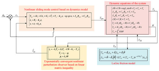
Figure 6.
Sliding mode control strategy based on nonlinear disturbance observer and dynamics model.
4.3. Position Tracking Performance Analysis of the Control Strategy
In order to verify the effectiveness of the sliding mode control strategy based on the nonlinear disturbance observer and dynamics model (LMIDOB+SMC), the variable stiffness actuator system is numerically simulated and compared with the position tracking performance analysis of the nonlinear sliding mode control strategy based on the dynamics model (SMC). In the analytic process, since the rotational inertia J of the default load is a constant value, and according to has an upper bound ξ, then ξ = 0.5 can be taken; take Ω = 0.1, and then according to Equation (10), it can be solved for , so take X= 3.9. The initial state of the controlled object then is: initial rotation angle of the load θ0
= 0, and initial rotational angular velocity θ0 = 0. In addition, the gain parameters kp1 = 1500, kp2 = 50, and η1 = 0.1 are taken, while the desired output of the load is θd = 11π/90sin(2πt-π/2) + 11π/90 rad.
First, the position tracking performance of the sliding mode control strategy based on the nonlinear disturbance observer and dynamics model at constant stiffness (100 Nm/rad) is investigated, and the specific results are shown in Figure 7.
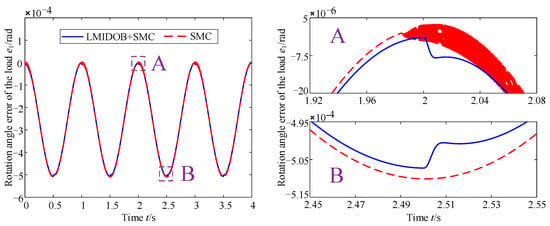
Figure 7.
Position tracking performance of control strategy at constant stiffness condition.
As can be seen in Figure 7, compared with the nonlinear sliding mode control strategy based on the dynamics model, the sliding mode control strategy based on the nonlinear disturbance observer and the dynamics model not only substantially improves the buffeting vibration of the position motor system, but also reduces the rotation angle error e1 of the load. Because the disturbance observer compensates well for the disturbance torque of the position motor system, this can also be seen in Figure 8. In addition, it is also seen from Figure 8 that, although the disturbance observer has eliminated the buffeting vibration of the position motor system as much as possible, when the position motor system is in the start-up phase, the torque composition of the system is complicated, and the disturbance observer cannot identify and compensate it quickly enough, so there is still a short period of buffeting vibration in the start-up phase, but it can shortly be eliminated. However, in general, the sliding mode control strategy based on the nonlinear disturbance observer and the dynamics model improves the buffeting vibration phenomenon of the position motor system at a constant stiffness condition, which is beneficial to the improvement of the static index of the system and the reduction of the mechanical wear and energy consumption of the system.
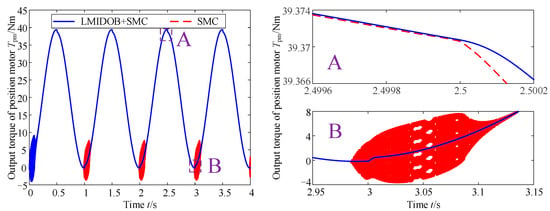
Figure 8.
Output torque of position motor at a constant stiffness condition.
Subsequently, the position tracking performance of the sliding mode control strategy based on the nonlinear disturbance observer and dynamics model at the variable stiffness (K = 50 × sin(πt) + 100 Nm/rad) condition is investigated, and the specific results are shown in Figure 9.
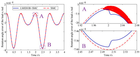
Figure 9.
Position tracking performance of control strategy at the variable stiffness condition.
From Figure 9, it can be seen that, firstly, the rotation angle error e1 at high stiffness is larger than that at low stiffness, as shown in Figure 9; secondly, combined with Figure 10, it can be seen that the buffeting vibration is not well-suppressed by the disturbance observer in the start-up phase because the torque composition of the system can be complicated, and at the rest of the time period, the buffeting vibration of the position motor system is indeed well suppressed, which also proves the effectiveness of the sliding mode control strategy based on the nonlinear disturbance observer and the dynamics model. In addition, comparing Figure 8 and Figure 10, it can be seen that the buffeting vibration is different around 1 s, 2 s, and 3 s, at the variable stiffness condition compared with the constant stiffness condition, which proves that the nonlinear sliding mode control strategy based on the dynamics model not only causes buffeting vibration in the variable stiffness actuator, but also does not cope well with the time-varying parameters in the system, while the sliding mode control strategy based on the nonlinear disturbance observer and the dynamics model can cope well with the effect of the stiffness change on the system, i.e., the control strategy can equate the difference between the actual object and the nominal model caused by the change of the model parameters to the control input when the stiffness of the variable stiffness actuator changes, and the equivalent compensation is introduced in the control to achieve complete control of the disturbance.
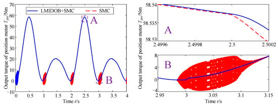
Figure 10.
Output torque of position motor at the variable stiffness condition.
Finally, the response time, stationary error and overshooting of the two control strategies under step response at different operating conditions are compared, and the results are shown in Table 2.

Table 2.
Performance comparison of two control strategies under step response.
As can be seen from Table 2, the stationary error, response time and the overshooting of the sliding mode control strategy based on nonlinear disturbance observer and the dynamics model are smaller compared with the nonlinear sliding mode control strategy based on the dynamics model at both constant and variable stiffness conditions, which sufficiently establishes the advantage of the sliding mode control strategy based on nonlinear disturbance observer and the dynamics model.
4.4. Experimental Verification
To verify the correctness and accuracy of the sliding mode control strategy based on the nonlinear disturbance observer and the dynamics model, experiments were conducted with a variable stiffness actuator system controlled by this control strategy, as shown in Figure 11. As can be seen in Figure 11, the experimental bench mainly consisted of a position motor system with variable stiffness actuator, an encoder (to measure the rotation angle of the load), and a controller (to collect the position information and torque value from the motor encoder and control the motor rotation through a control strategy).
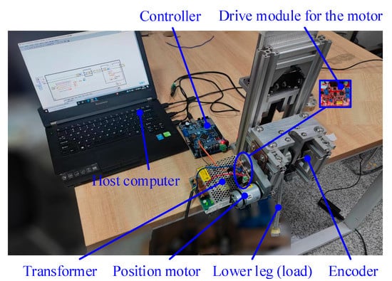
Figure 11.
Experimental platform for variable stiffness actuator.
The control strategy verification experiment of the variable stiffness actuator system is conducted by inputting the desired angle of rotation of the load as θd = 11π/90sin(πt-π/2) + 11π/90 rad to the controller. In addition, in the experiment, the change of the rotation angle of the load also causes the change of the stiffness of the variable stiffness actuator, therefore, this experiment belongs with the experiment conducted at the variable stiffness condition, and the stiffness change law can be derived according to Equation (2). The specific experimental results are shown in Figure 12.
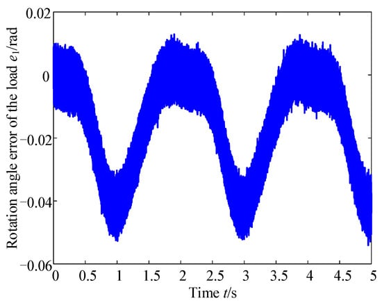
Figure 12.
Experimental error.
From Figure 12, it can be seen that, firstly, the theoretical curve of the rotation angle error of the load is consistent with the trend of the experimental curve, and the rotation angle error of the load is always less than 5%, which proves the validity of the experimental method and of the experimental platform, as well as the correctness of the established model. The fluctuation of the experimental measurement error is much larger than the theoretical error, because in the actual experiment, there are machining errors, assembly errors, and the noise of the sensor, all of which affect the actual rotation angle of the load, so the fluctuation of the experimental measurement error is much larger than the theoretical error.
5. Conclusions
In this paper, a dynamic model of the variable stiffness actuator system considering friction and gravity is established based on the two-inertia-system theory, and the dynamic performance of the system is studied based on the established dynamic model. Then, the control strategy of the variable stiffness actuator system is studied, which hopes to eliminate or reduce the influence of friction and gravity on the system, so that the position adjustment of the load (rotation of the lower leg) can be quicker and more stable, and the correctness and effectiveness of this control strategy are then verified through experiments. The following conclusions are obtained.
(1) Friction has a great influence on the dynamic performance of the high-precision variable stiffness actuator system at both the constant and variable stiffness conditions, so the influence of friction on the system should be eliminated as much as possible. At the constant stiffness condition, friction consumes part of the energy of the variable-stiffness actuator system, so the amplitude of the rotation angle θpm of the position motor and the rotation angle θ of the load are reduced, the time to reach the maximum value of the rotation angle is lagged, and the rotational angular velocity of the load appears to crawl; at the variable stiffness condition, as the stiffness of the actuator increases, the system becomes more stable, but the hysteresis caused by friction becomes more pronounced.
(2) Gravity has a great influence on the dynamic performance of the high-precision variable stiffness actuator system at both the fixed and variable stiffness conditions, so the influence of gravity on the system should be eliminated as much as possible. Whether at the constant stiffness condition or the variable stiffness condition, the rotation angle under the same torque is reduced after considering gravity, because part of the torque provided by the position motor is offset by the gravity of the load. In addition to the above, the hysteresis due to friction is reduced by gravity.
(3) The sliding mode control strategy based on a nonlinear disturbance observer and dynamics model can eliminate the adverse effects of gravity and friction on the variable stiffness actuator system, so that its load can achieve the desired output more accurately, and the nonlinear disturbance observer suppress the buffeting vibration of the variable stiffness actuator system; the correctness and effectiveness of this control strategy are verified through experiments.
Author Contributions
Methodology, Z.Y.; resources, Z.Y.; writing—original draft preparation, Z.Y.; writing—review and editing, J.X. and R.C.; supervision, H.Y.; project administration, X.L.; funding acquisition, X.L. All authors have read and agreed to the published version of the manuscript.
Funding
This research was funded by National Natural Science Foundation of China (NSFC) (No. 51875092), National Key Research and Development Project of China (No. 2020YFB2007802), Natural Science Foundation of Ningxia Province (No. 2020AAC03279).
Data Availability Statement
Not applicable.
Conflicts of Interest
The authors declare no conflict of interest.
Nomenclature
| J | Rotational inertias of the lower leg |
| J1 | Rotational inertias of the ball screw |
| Jpm | Rotational inertias of the position motor system |
| Jsm | Rotational inertias of the stiffness motor system |
| C | Damping coefficients of the lower leg |
| C1 | Damping coefficients of the ball screw |
| Cpm | Damping coefficients of the position motor |
| Csm | Damping coefficients of the stiffness motor |
| θ | Rotation angles of the lower leg |
| θ1 | Rotation angles of the ball screw |
| θpm | Rotation angles of the position motor |
| θsm | Rotation angles of the stiffness motor |
| Tpm | Input torques of the position motor |
| Tsm | Input torques of the stiffness motor |
| Ka | Torsional stiffness of the drive system of the position motor system |
| Ka1 | Torsional stiffness of the drive system of the stiffness motor system |
| Ca | Damping coefficients of the drive system of the position motor system |
| Ca1 | Damping coefficients of the drive system of the stiffness motor system |
| Ta | Input torques of the lower leg |
| Ta1 | Input torques of the ball screw |
| Td | Total disturbances of the position motor system |
| Tr | Total disturbances of the stiffness motor system |
| K | Stiffness of the variable stiffness actuator |
| Tvs | Elastic torque due to the variable stiffness system |
| m | Mass of the lower leg |
| L1 | Distance between the center of mass of the lower leg and the axis |
| g | Acceleration of gravity |
| E | Young’s modulus of the cantilever beam |
| I | Inertia moment of the cantilever beam |
| e | Eccentric distance of the eccentric cam |
| rt | Radius of the roller |
| r | Distance between the center of the roller and the axle center of the eccentric cam |
| h | Maximum travel distance of the push rod |
| θ0 | Rotation angles of the eccentric cam at the maximum extending stroke |
| δ0 | Friction stiffness coefficient of the system |
| δ1 | Friction damping coefficient of the system |
| δ2 | Viscous friction coefficient of the system |
| z11 | Internal friction state of the system |
| Tc1 | Coulomb friction moment of the system |
| Ts1 | Static friction moment of the system |
| Stribeck velocity of the system | |
| e1 | Tracking error of the variable stiffness actuator system |
| e2 | Filtering error of the variable stiffness actuator system |
| s1 | Sliding mode function of the variable stiffness actuator system |
| kp1 | Gain matrix of the control strategy |
| kp2 | Gain matrix of the control strategy |
References
- Chen, R.Z.; Li, X.P.; Yang, Z.M.; Xu, J.C.; Yang, H.X. A variable positive-negative stiffness joint with low frequency vibration isolation performance. Measurement 2021, 185, 110046. [Google Scholar] [CrossRef]
- Braun, D.J.; Chalvet, V.; Chong, T.H.; Apte, S.S.; Hogan, N. Variable stiffness spring actuators for low-energy-cost human augmentation. IEEE Trans. Robot. 2019, 35, 1435–1449. [Google Scholar] [CrossRef]
- Moltedo, M.; Cavallo, G.; Baček, T.; Lataireb, J.; Vanderborghta, B.; Lefebera, D.; Rodriguez-Guerreroa, C. Variable stiffness ankle actuator for use in robotic-assisted walking: Control strategy and experimental characterization. Mech. Mach. Theory 2019, 134, 604–624. [Google Scholar] [CrossRef]
- Calanca, A.; Muradore, R.; Fiorini, P. A review of algorithms for compliant control of stiff and fixed-compliance robots. IEEE/ASME Trans. Mech. 2016, 21, 613–624. [Google Scholar] [CrossRef]
- Jafari, A. Coupling between the output force and stiffness in different variable stiffness actuators. Actuators 2014, 3, 270–284. [Google Scholar] [CrossRef]
- Xu, Y.P.; Guo, K.; Sun, J.; Li, J.F. Design, modeling and control of a reconfigurable variable stiffness actuator. Mech. Syst. Signal Pr. 2021, 160, 107883. [Google Scholar] [CrossRef]
- Hurst, J.W.; Chestnutt, J.E.; Rizzi, A.A. The actuator with mechanically adjustable series compliance. IEEE Trans. Robot. 2010, 26, 597–606. [Google Scholar] [CrossRef]
- Yang, Z.M.; Li, X.P.; Xu, J.C.; Chen, R.Z.; Yang, H.X. A new low-energy nonlinear variable stiffness actuator for the knee joint. Mech. Based Des. Struc. 2022. [Google Scholar] [CrossRef]
- Tonietti, G.; Schiavi, R.; Bicchi, A. Design and Control of a Variable Stiffness Actuator for Safe and Fast Physical Human/Robot Interaction. In Proceedings of the IEEE International Conference on Robotics and Automation, Barcelona, Spain, 18–22 April 2005; pp. 526–531. [Google Scholar]
- Schiavi, R.; Grioli, G.; Sen, S.; Bicchi, A. VSA-II: A novel prototype of variable stiffness actuator for safe and performing robots interacting with humans. In Proceedings of the IEEE International Conference on Robotics and Automation, Pasadena, CA, USA, 19–23 May 2008; pp. 2171–2176. [Google Scholar]
- Hu, X.Q.; Song, Z.B.; Ma, T.Y. Novel design method for nonlinear stiffness actuator with user-defined deflection-torque profiles. Mech. Mach. Theory 2020, 146, 103712. [Google Scholar] [CrossRef]
- Liu, Y.; Cui, S.; Sun, Y. Mechanical design and analysis of a novel variable stiffness actuator with symmetrical pivot adjustment. Front. Mech. Eeng.-PRC 2021, 16, 711–725. [Google Scholar] [CrossRef]
- Jafari, A.; Tsagarakis, G.N.; Caldwel, D.G. A novel intrinsically energy efficient actuator with adjustable stiffhess (AwAS). IEEE/ASME Trans. Mech. 2013, 18, 355–365. [Google Scholar] [CrossRef]
- Jafari, A.; Tsagarakis, G.N.; Sardellim, I.; Caldwel, D.G. A new actuator with adjustable stiffness based on a variable ratio lever mechanism. IEEE/ASME Trans. Mech. 2014, 19, 55–63. [Google Scholar] [CrossRef]
- Zhai, M.; Zhang, B.; Li, X.; Long, Z. Design and implementation of permanent and electromagnet composite vibration isolation system based on negative stiffness theory. Actuators 2023, 12, 44. [Google Scholar] [CrossRef]
- Sun, J.T.; Guo, Z.; Zhang, Y.B.; Xiao, X.H.; Tan, J.R. A novel design of serial variable stiffness actuator based on an archimedean spiral relocation mechanism. IEEE/ASME Trans. Mech. 2018, 23, 2121–2131. [Google Scholar] [CrossRef]
- Sun, J.T.; Guo, Z.; Sun, D.Y.; He, S.Y.; Xiao, X.H. Design, modeling and control of a novel compact, energy-efficient, and rotational serial variable stiffness actuator (SVSA-II). Mech. Mach. Theory 2018, 130, 123–136. [Google Scholar] [CrossRef]
- Jimenez-Fabian, R.; Weckx, M.; Rodriguez-Cianca, D.; Lefeber, D.; Vanderborght, B. Online reconfiguration of a variable-stiffness actuator. IEEE/ASME Trans. Mech. 2018, 23, 1866–1876. [Google Scholar] [CrossRef]
- Palli, G.; Melchiorri, C.; Luca, A.D. On the feedback linearization of robots with variable joint stiffness. In Proceedings of the IEEE International Conference on Robotics and Automation, Pasadena, CA, USA, 19–23 May 2008; pp. 1753–1759. [Google Scholar]
- Sardellitti, I.; Medrano-Cerda, G.A.; Tsagarakis, N.; Jafari, A.; Caldwell, D.G. Gain scheduling control for a class of variable stiffness actuators based on lever mechanisms. IEEE Trans. Robot. 2013, 29, 791–798. [Google Scholar] [CrossRef]
- Liu, L.; Leonhardt, S.; Misgeld, B.J.E. Experimental validation of a torque-controlled variable stiffness actuator tuned by gain scheduling. IEEE/ASME Trans. Mech. 2018, 23, 2109–2120. [Google Scholar] [CrossRef]
- Chen, W.H.; Yang, J.; Guo, L.; Li, S.H. Disturbance-observer-based control and related methods—An overview. IEEE Trans. Ind. Electron. 2016, 63, 1083–1095. [Google Scholar] [CrossRef]
- Sariyildiz, E.; Chen, G.; Yu, H.Y. Robust trajectory tracking control of multimass resonant systems in state space. IEEE Trans. Ind. Electron. 2017, 64, 9366–9377. [Google Scholar] [CrossRef]
- Sariyildiz, E.; Mutlu, R.; Yu, H.Y. A sliding mode force and position controller synthesis for series elastic actuators. Robotica 2019, 38, 15–28. [Google Scholar] [CrossRef]
- Oh, S.; Kong, K. High-precision robust force control of a series elastic actuator. IEEE/ASME Trans. Mech. 2017, 22, 71–80. [Google Scholar] [CrossRef]
- Park, Y.; Paine, N.; Oh, S. Development of force observer in series elastic actuator for dynamic control. IEEE Trans. Ind. Electron. 2017, 65, 2398–2407. [Google Scholar] [CrossRef]
- Guo, J.S.; Tian, G.H. Robust tracking control of the variable stiffness actuator based on the lever mechanism. Asian J. Control. 2020, 22, 729–749. [Google Scholar] [CrossRef]
- Petit, F.; Dietrich, A.; Albu-Schäffer, A. Generalizing torque control concepts: Using well-established torque control methods on variable atiffness robots. IEEE Robot. Autom. Mag. 2015, 22, 37–51. [Google Scholar] [CrossRef]
- Kong, K.; Bae, J.; Tomizuka, M. Control of rotary series elastic actuator for ideal force-mode actuation in human–robot interaction applications. IEEE/ASME Trans. Mech. 2009, 14, 105–118. [Google Scholar] [CrossRef]
- Bang, J.S.; Shim, H.; Park, S.K.; Seo, J.H. Robust tracking and vibration suppression for a two-Inertia system by combining backstepping approach with disturbance observer. IEEE Trans. Ind. Electron. 2010, 57, 3197–3206. [Google Scholar] [CrossRef]
- Shang, D.; Li, X.; Yin, M.; Li, F. Control Method of Flexible Manipulator Servo System Based on a Combination of RBF Neural Network and Pole Placement Strategy. Mathematics 2021, 9, 896. [Google Scholar] [CrossRef]
- Wu, Q.C.; Wang, X.S.; Chen, B.; Wu, H.T. Modeling, online identification, and compensation control of single tendon sheath system with time-varying configuration. Mech. Syst. Signal Pr. 2019, 130, 56–73. [Google Scholar] [CrossRef]
- Shao, Z.; Wu, Q.; Chen, B.; Wu, H.; Zhang, Y. Modeling and inverse control of a compliant single-tendon-sheath artificial tendon actuator with bending angle compensation. Mechatronics 2019, 63, 102262. [Google Scholar] [CrossRef]
- Lu, L.; Wu, Q.; Chen, X.; Shao, Z.; Chen, B.; Wu, H. Development of a sEMG-based torque estimation control strategy for a soft elbow exoskeleton. Robot. Auton. Syst. 2018, 111, 88–98. [Google Scholar] [CrossRef]
- Yang, Z.M.; Li, X.P.; Chen, R.Z.; Shang, D.Y.; Xu, J.C.; Yang, H.X. Dynamic performance analysis of the variable stiffness actuator considering gap and friction characteristics based on two-inertia-system. Mech. Mach. Theory 2022, 168, 104584. [Google Scholar] [CrossRef]
- Wang, Q.B.; Xu, K.; Huai, T.S.; Ma, H.; Wang, K. A mesh stiffness method using slice coupling for spur gear pairs with misalignment and lead crown relief. Appl Math. Model. 2021, 90, 845–861. [Google Scholar] [CrossRef]
- Chanachai, T.; Pouyan, R.S.; Peyman, R.S.; Nima, R.; Sayan, S.; Suraparb, K.; Silvia, T. Dynamic response of fluid-conveying hybrid smart carbon nanotubes considering slip boundary conditions under a moving nanoparticle. Mech. Adv. Mater. Struc. 2022. [Google Scholar] [CrossRef]
- Johanastrom, K.; Canudas-de-Wit, C. Revisiting the LuGre friction model. IEEE Contr. Syst. Mag. 2008, 28, 101–114. [Google Scholar] [CrossRef]
- Chen, W.H.; Balance, D.J.; Gawthrop, P.J.; O’Reilly, J. A nonlinear disturbance observer for robotic manipulators. IEEE Trans. Ind. Electron. 2000, 47, 932–938. [Google Scholar] [CrossRef]
- Levant, A. Robust exact differentiation via sliding mode technique. Automatica 1998, 34, 379–384. [Google Scholar] [CrossRef]
- Mohammadi, A.; Tavakoli, M.; Marquez, H.J.; Hashemzadeh, F. Nonlinear disturbance observer design for robotic manipulators. Control. Eng. Pract. 2013, 21, 253–267. [Google Scholar] [CrossRef]
Disclaimer/Publisher’s Note: The statements, opinions and data contained in all publications are solely those of the individual author(s) and contributor(s) and not of MDPI and/or the editor(s). MDPI and/or the editor(s) disclaim responsibility for any injury to people or property resulting from any ideas, methods, instructions or products referred to in the content. |
© 2023 by the authors. Licensee MDPI, Basel, Switzerland. This article is an open access article distributed under the terms and conditions of the Creative Commons Attribution (CC BY) license (https://creativecommons.org/licenses/by/4.0/).