Article

Numerical Study of a Phase Change Material Energy Storage Tank Working with Carbon Nanotube–Water Nanofluid under Ha’il City Climatic Conditions

1
Department of Mechanical Engineering, College of Engineering, University of Ha’il, Ha’il City 81541, Saudi Arabia
2
Mechanical Engineering Department, College of Engineering, University of Babylon, Hilla 51002, Iraq
3
Laboratory of Metrology and Energy Systems, Department of Energy Engineering, University of Monastir, Monastir 5000, Tunisia
4
Laboratory of Electrochemistry and Environment (LEE), National Engineering School of Sfax (ENIS), University of Sfax, Sfax 3038, Tunisia
5
Laboratory of Applied Fluid Mechanics, Environment and Process Engineering “LR11ES57”, National School of Engineers of Sfax (ENIS), University of Sfax, Soukra Road Km 3.5, Sfax 3038, Tunisia
6
Laboratoire de Mécanique, Matériaux et Procédés LR99ES05, Ecole Nationale Supérieure d’Ingénieurs de Tunis, Université de Tunis, 5 Avenue Taha Hussein, Montfleury, Tunis 1008, Tunisia
7
Department of Software Engineering, College of Computer Engineering and Sciences, Prince Sattam Bin Abdulaziz University, P.O. Box 151, Al-Kharj 11942, Saudi Arabia
8
College of Engineering and Technology, American University of the Middle East, Egaila 54200, Kuwait
9
Department of Pure and Applied Mathematics, School of Mathematical Sciences, Sunway University, No. 5, Jalan Universiti, Bandar Sunway, Petaling Jaya 47500, Selangor Darul Ehsan, Malaysia
10
Symbiosis Institute of Technology, Symbiosis International University, Pune 412115, India
*
Author to whom correspondence should be addressed.
Mathematics 2023, 11(4), 1057; https://doi.org/10.3390/math11041057
Submission received: 28 December 2022 / Revised: 20 January 2023 / Accepted: 11 February 2023 / Published: 20 February 2023

Abstract

:
A numerical investigation of a phase change material (PCM) energy storage tank working with carbon nanotube (CNT)–water nanofluid is performed. The study was conducted under actual climatic conditions of the Ha’il region (Saudi Arabia). Two configurations related to the absence or presence of conductive baffles are studied. The tank is filled by encapsulated paraffin wax as the PCM, and CNT–water nanofluid flows through the capsules. The main goal is to increase the temperature of the PCM to 70 °C in order to store the thermal energy, which can then be used during the night and cloudy weather. Numerical computations are made using the finite element method (FEM) based on actual measured weather conditions. Climate conditions were collected from a weather station located on the roof of the engineering college’s building at the University of Ha’il. The collected data served as input to the numerical model, and the simulations were performed for three months (December, March, and July). The solid CNT volume fraction range was (0 ≤ ϕ ≤ 0.05) and the nanofluid volume flow rate ranged was (0.5 L/min ≤ V ≤ 3 L/min). For both considered cases (with and without baffles), it was found that the use of CNT–nanofluid led to a reduction in the charging time and enhanced its performance. An increase in the volumetric flow rate was found to accelerate the melting process. The best performances of the storage tank occurred during July due to the highest solar irradiation. Furthermore, it was found that the use of baffles had no beneficial effects on the melting process.

1. Introduction

Solar energy is the most well-known type of renewable energy, but one of its serious problems is its instability and randomness, especially during the sunrise and sunset periods [1,2,3]. For this reason, the thermal energy storage tank can be considered an essential component of the solar water heating system (SWHs) [4,5]. In these systems, heat is mainly stored as latent heat in a tank filled with phase change materials (PCM). Saudi Arabia (especially the Ha’il region) is characterized by significant solar intensity potential. For solar water heating applications, the most principal issue is meeting the demand during night and cloudy periods. Heat storage is therefore an excellent solution to bridge this gap between energy supply and demand [6,7]. Due to their exceptional thermal storage capacity, PCMs can be considered as an appropriate solution, as they have proven their efficiency over the last few years [8,9,10,11,12,13,14]. The two principal families of PCMs are metallic and non-metallic materials. The first type such as aluminum and tin are costly, whereas the second type such as molten salt, fatty acids and paraffin wax are cheap and available [15]. Paraffin wax is one of the most famous and widely used PCMs in thermal applications.
The use of PCMs in solar heaters and energy storage tanks has received increasing attention from many authors. Karthikeyan et al. [16] numerically examined the efficiency of a storage unit filled with PCM encapsulated in spherical balls using the enthalpy method. The fluid inlet temperature, flow rate and the size of PCM balls were investigated. The authors deduced that the efficiency of the storage tank was optimized by increasing the exchange surface using smaller balls and by increasing the mass flow rate. Numerical modeling of a coiled energy storage water tank was carried out by Abdelsalam et al. [17]. The authors mentioned that the stored energy was improved from two to five times by using PCM compared to the system using only water. Delgado et al. [18] experimentally investigated the heat transfer in a coiled stirred tank including a paraffin emulsion as PCM. The experimental results indicated that even at low rotational speed, the thermal storage efficiency was significantly increased. Meng and Zhang [19] studied the performance of a latent heat storage unit made up of a tube-in-tank using copper foam and paraffin as PCMs. It has been demonstrated that the considered unit can be used in large-scale storage systems. The numerical analysis of solar energy storage units filled with PCM modules under the climatic conditions of the city of Marrakech (Morocco) was studied by Bouhal et al. [20]. Two numerical codes were established; the first code considered the problem using the apparent specific heat capacity technique, whereas the second code used the enthalpy method. The apparent heat capacity approach was more accurate and relevant than the enthalpy method. Huang et al. [21] studied the thermal stratification in a storage tank filled with sodium acetate trihydrate as PCM. The effect of the PCMs location (i.e., top, middle, and bottom) on the thermal stratification characteristics for various discharge flow rates was also examined. The authors concluded that the water mixing became significant when the PCM was located at the bottom or near the inlet. In addition, the energy storage in the tank was enhanced by about 3% by using PCMs. Mousa et al. [22] investigated the effect of using Tricosane as a PCM tank. They concluded that the time required to maintain the water temperature at or above 45 °C was more than doubled compared to the case without using PCM. Lee et al. [23] modeled a tank including 1620 spherical capsules filled with either heating or cooling PCM. The authors mentioned that the suggested compact tank was efficient and met both heating and cooling demands. Huang et al. [24] proposed a modified SWHs configuration by coupling the water tank and PCM unit in series. The model was built using TRNSYS. The sodium acetate trihydrate mixtures were adopted as a PCM. Three different configurations were simulated: a conventional water tank, a water tank in-series with a PCM unit and a water tank in parallel with a PCM unit. It was observed that the in-series system has the best performance. Carmona et al. [25] studied a hot water storage tank operated with paraffin wax filled in cylindrical bottles. The effects of tank aspect ratio, water flow rate, ratio of PCM in the tank and its properties on the exergy and energy efficiencies of the system were evaluated. They concluded that PCM properties, such as latent heat of fusion and average melting temperature, had positive effects on the exergy and energy efficiencies of the system. Furthermore, these efficiencies were increased by decreasing the water flow rate.
Recently, the use of nanoparticles to improve the performance of energy storage systems has been the subject of several studies. The experimental analysis of the performance of a flat plate solar collector using pure paraffin wax and paraffin wax with Cu nanoparticles was performed by Saw et al. [26]. The collector efficiency was enhanced by about 6.9% and 8.4% when paraffin and (paraffin-Cu) nanocomposite are used, respectively. Al-Kayiem and Lin [27] designed and fabricated an experimental setup to study a solar collector at various inclination angles of 10°, 20° and 30° connected to a heat storage tank. The experiments included three cases (without PCM, with PCM and PCM-Cu nanocomposite). The highest efficiency of 52% was achieved when PCM-Cu nanocomposite was used at inclination angle of 10°. Xiao et al. [28] studied the effect of adding graphene nano-sheets into a phase change material (mixture of NaNO3 and KNO3) for solar energy storage. The fraction of nanoparticles varied from 5% to 20%. The authors noted that the conductivity of nano-PCM was significantly enhanced, by a factor of two to seven times, compared to pure PCM, and that the storage and energy recovery time was considerably reduced. Mahdi and Nsofor [29] studied the solidification of a Al2O3-nano-PCM in a triplex tube. Volumetric concentrations of nanoparticles between 3 and 8% were suitable to save 8–20% of the total solidification time. Lin and Al-Kayiem [30] investigated the performance of a nano-PCM synthesized by mixing 20 nm-sized Cu nanoparticles with paraffin wax. They found a 1.7% improvement in efficiency when 1.0% Cu nanoparticles were added. Kant et al. [31] numerically studied the influence of mixing graphene nanosheets with different PCMs on the melting process. Three distinct types of PCM were selected, namely paraffin, inorganic and organic. The nanoparticles were mixed at three different volumetric fractions of 1%, 3%, and 5%. The authors showed that the addition of graphene nanoparticles increased the melting rate. The experimental investigation of the performance of SWHs operating with a CuO–paraffin wax nanocomposite overnight was carried out by Mandal et al. [32]. They used the electrochemical discharge method to synthetize CuO nanoparticles. The water outlet temperature, nanocomposite temperature and heat transfer decreased by increasing the concentration of nanoparticles. The study of the heat storage process of nano-encapsulated-PCM (NEPCM) was performed by Kumar and Mylsamy [33] under the outdoor conditions of Coimbatore city, India. Paraffin with CeO2 nanoparticles was selected as NEPCM, and the experiments covered five cases (without paraffin, with pure paraffin and NEPCM at three mass fractions of nanoparticles). It was concluded that the daily energy and exergy efficiencies reached their maximum values of 79.2% and 5.1%, respectively, when NEPCM was used at a mass fraction of 1%. Mandal et al. [34] experimentally investigated the influence of using CuO–paraffin wax nanocomposite on the performance of SWHs. The results confirmed that the use of nanoparticles improved the water outlet temperature. Kumar et al. [35] experimentally explored the effect of a hybrid nano composite PCM (HNCPCM) on the efficiency of an evacuated tube solar heater. They carried out five different experiments (without paraffin, with pure paraffin and HNCPCM for mass fractions of 0.5%, 1% and 2% of SiO2/CeO2 hybrid nanoparticles). It was found that the improvement in energy and exergy efficiencies reached maximum values of 19.4% and 1.28%, respectively, when HNCPCM was used at a mass fraction of 1%. The analysis of an energy storage tank filled with nano-PCMs was performed by Al-Jethelah et al. [36]. Coconut oil was considered as a PCM, while CuO was considered as nanoparticles. It was mentioned that the melting process was improved by adding CuO nanoparticles to PCM. Other interesting articles on nano-enhanced PCMs are available in the literature [37,38,39,40,41,42].
On the other hand, fins or baffles can be used to improve the performance of thermal storage systems. One of the main functions of fins is to improve the melting and solidification time of PCM [43]. The fins are placed in the heat storage tank and designed in different shapes: circular, corrugated, triangular, radial, rectangular, V-shaped, and cylindrical. The baffles are attached in order to increase the heat transfer surface or to guide the fluid flow. Gharebaghi and Sezai [44] inserted a grid of fins to increase the heat transfer rate in storage modules filled with a PCM. The energy storage rate was successfully increased by using the internal fins. Touati et al. [45] studied the heat discharging in a multiple PCMs-filled solar storage tank. It was mentioned that the heat transfer was accelerated by the use of fins, which reduced the discharge time. Sathe and Dhoble [46] investigated the thermal performance of PCM melting in a rectangular container heated from the top. A comparison was made between a container with and without fins for various inclination angles and PCM layer thickness. It was observed that the duration of PCM melting was increased by decreasing the inclination angle and increasing PCM thickness. In addition, heat transfer was intensified by about six to nine times for the finned container tilted by 90° compared to the finless container. Gürtürk and Kok [47] studied the effect of the fin surface area on the solidification and melting processes of paraffin wax. It was found that the melting process was accelerated by using fins up to a certain limit.
Few researchers combined the use of nanoparticles and fins. Singh et al. [48] proposed a novel fin design incorporated in a thermal storage system. They analyzed the cost reduction of a 23-kW solar absorption chiller as a case study by using the suggested fin design. They mentioned that the melting time was about 43% lower for the proposed design with 5% of graphene nanosheets. The maximum heat transfer rate was achieved by decreasing the fin size. Mousavi et al. [49] investigated the melting process in a vertical cylindrical unit filled with PCM mixed with Al2O3 nanoparticles. The authors showed that using Al2O3 nanoparticles (without fins) enhanced the melting time by about 5.5%, while it is improved by about 28% using nano-PCM and fins.
Based on the comprehensive review of the previous literature and the authors’ knowledge of the field of study, to date, there are no papers coupling the use of baffles in an open solar energy storage tank with the use of CNT nanofluid as working fluid and encapsulated PCM. The encapsulation technique was recommended by Lin and Al-Kayiem [30]. In addition, tracking the melting front in a tank filled with encapsulated PCM and operated with water containing CNTs coming from a solar collector under real-world climate conditions has not been considered numerically before. This point is particularly important in the design of energy storage tanks.

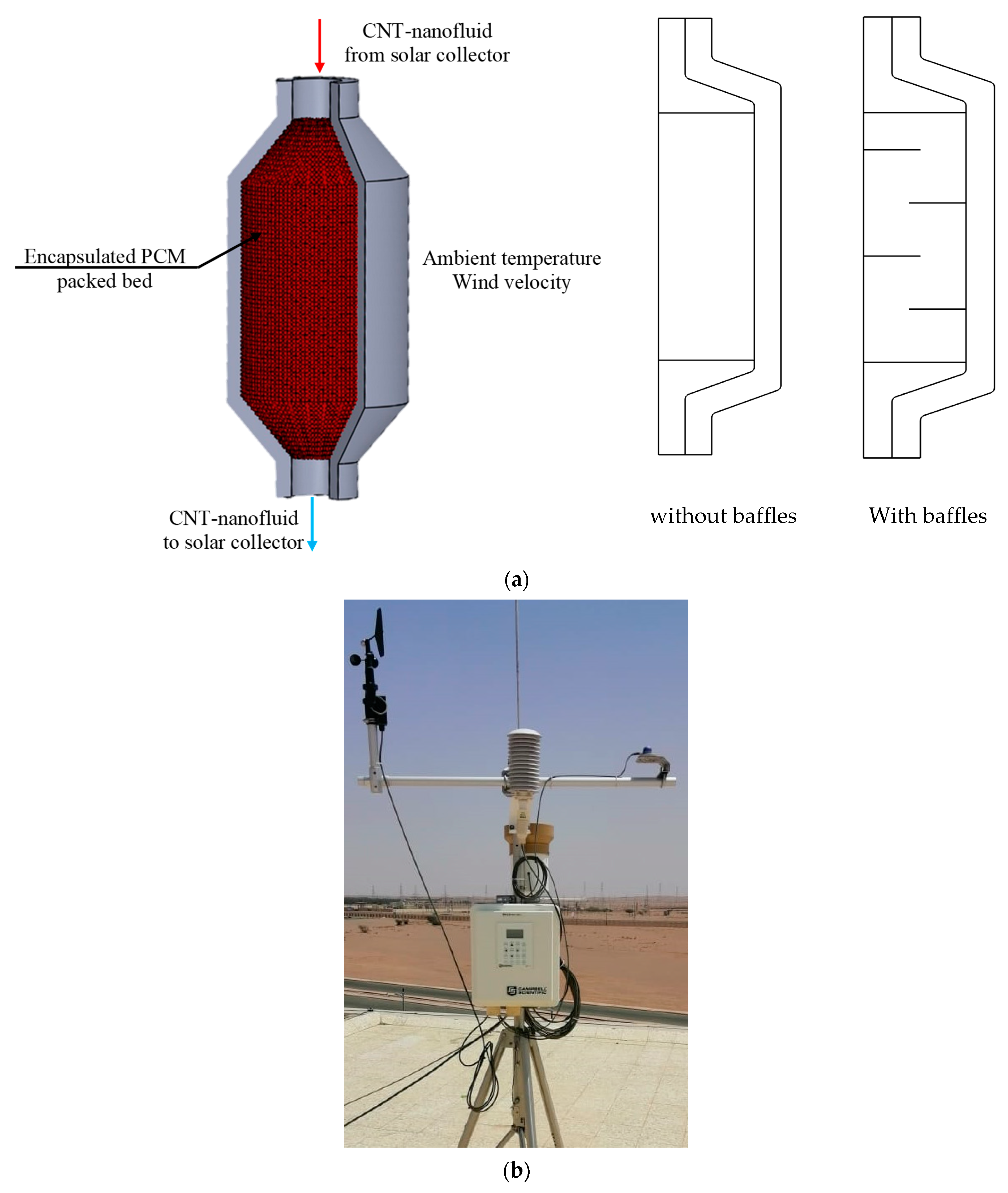
2. Studied Configuration, Mathematical Formulation, and Numerical Procedure

The system considered in this work consists of a flat plate solar collector connected to an energy storage tank. The tank is filled with encapsulated PCM (packed bed), and a CNT–nanofluid flows through the capsules after gaining heat from the closed-loop flat solar collector with a surface Sc = 2 m2 and an average thermal efficiency of η = 0.68 (Figure 1a). Two configurations are studied: with and without baffles (four horizontal baffles), as presented in Figure 1a. A weather station (Figure 1b) situated at University of Ha’il was used to collect the climatic conditions (solar irradiation, ambient temperature, and wind velocity) that are used as input of the numerical model.
The analysis was performed under actual climatic conditions of the Ha’il region. The thermal storage tank is filled with encapsulated paraffin wax. The capsules are spherical in shape with a diameter dp = 55 mm and negligible thickness. The porosity of the embedded capsules is ε p = 0.49. The paraffin thermophysical properties are listed in Table 1.
During the charging process, the paraffin and nano-paraffin absorb heat during the daytime and release it during the discharge process at night. Once the paraffin reaches 60 °C, it begins to melt and absorbs extra latent heat as it moves from the solid to the liquid phase. This heat lost by the paraffin during the night is used to warm the water. When the paraffin attains 70 °C as a minimum local temperature (extra heat is stored as sensible heat), the nanofluid flow is directed to a heat exchanger (instead of the storage tank) to heat the water that will be supplied to the users. This was practically controlled by using a three-way valve and a temperature control system. The main goal of the present work is to store the paraffin wax at a minimum local temperature of 70 °C to use it to heat the water during the night and cloudy times. This temperature is chosen to ensure the melting of all PCM.
For modeling this problem, a single-phase nanofluid model approach is applied. Under the assumptions of a Newtonian and incompressible fluid, the governing equations are written as follows:
-
For the nanofluid region
u = 0
ρ ( u ) u = [ p I + μ ( u + ( u ) T ) ]
ρ C p ( T t + u T ) = ( k T )
-
For the PCM region
u = 0
1 ε p ρ ( u ) u ε p = [ p I + μ ε p ( u + ( u ) T ) ] ( μ κ 1 + β p ρ | u | ) u
κ denotes the Kozeny–Carman permeability
κ = d p 2 150 ε p ( 1 ε p ) 2
ρ C p ( T t + u T ) = ( k T )
The thermo-physical properties in the PCM phase are calculated by the following relations:
ρ = ( 1 α ) ρ f 1 + α   ρ f 2
C p = 1 ρ ( ( 1 α ) ρ f 1 C p , f 1 + α   ρ f 2 C p , f 2 ) + L α m T
k = ( 1 α ) k f 1 + α   k f 2
α m = 1 2 α ρ f 2 ( 1 α )   ρ f 1 ( 1 α )   ρ f 1 + α ρ f 2
α is the phase change function.
α { 0   if   T < ( T m Δ T m 2 ) 1   if   T > ( T m + Δ T m 2 )
f1, f2 and L stand for liquid phase, solid phase, and latent heat of melting, respectively.
The tank inlet temperature is evaluated using the utile heat collected by the flat solar collector.
T i n = T o u t + η · A c · I r ρ n f · V i n · c p n f
Convective heat transfer condition is applied at the boundaries in contact with surrounding air. The tank is considered as a vertical cylinder under external flow at ambient temperature and velocity:
q 0 = h · ( T a m b T )
with:
h = k D ( 0.3 + 0.62 · Re D 1 / 2 · Pr 1 / 3 ( 1 + ( 0.4 Pr ) 2 / 3 ) 1 / 4 · ( 1 + ( Re D 282,000 ) 5 / 8 ) 4 / 5 )
In order to couple the heat transfer in the interface between the nanofluids phase and the solids phase (paraffin capsules), the local thermal nonequilibrium principle was adopted [51]. The heat exchange can then be modulated by the following heat source.
( 1 α ) ρ s C p , s T s t [ ( 1 α ) k s T s ] = q s f ( T f T s ) + ( 1 α ) Q s
α ρ f C p , f ( T f t + u f T f ) + [ β k f T f ] = q s f ( T s T f ) + α Q f
Q f , Q s and q s f represent, respectively, the nanofluid heat sources, the solid heat sources, and the interstitial coefficient of convective transfer.
1 q s f = 2 r p a s f ( 1 k f N u + 1 k s β )
β is set to 10 (spherical shape). The solid–fluid Nusselt number is defined as [52]:
N u = 2 + 1.1 Pr 1 / 3 Re p 0.6
The particle Prandtl and Reynolds numbers are given as:
Pr = μ C p , f k f ; Re p = 2 r p ρ f | u f | μ
The properties of the CNT–water nanofluid are expressed as:
-
Density:
ρ n f = ϕ   ρ C N T + ( 1 ϕ ) ρ f
-
Heat capacitance:
( ρ · C p ) n f = ϕ · ( ρ · C p ) C N T + ( 1 ϕ ) · ( ρ · C p ) f
-
Dynamic viscosity (Nan’s model) [53]:
μ n f μ f = ( 1 ϕ a v ϕ m ) 2
with
ϕ a g = ϕ ( r a r p ) 3 D ;   ϕ m = 3.61 × 10 2 ;   r a r p = 4.41 ; D = 2.1
-
Thermal conductivity (Nan’s model) [54]:
λ n f λ f = 3 + ϕ ϕ a g ( β 11 β 33 ) 3 ϕ β 11
with:
β 11 = λ 11 λ f λ f + 0.5 ( λ C N T λ f )   ;   β 33 = λ 33 λ f 1   ;   λ 11 = λ C N T 1 + 2 R k λ f λ C N T d p λ f   ;   λ 33 = λ C N T 1 + 2 R k · λ f λ C N T l p λ f
where:
  • λ 11 , λ 33 are the transverse and longitudinal thermal conductivities;
  • d p = 9.2 nm;
  • l p =1.5 μm; and
  • R k = 8.83 × 10 8 m 2 K / W .
The properties of water and CNT are illustrated in Table 2.
A Galerkin weighted residual finite element method (FEM) [56] has been used to solve the governing equations. The simulated domain is divided into triangular elements. Different orders of Lagrange triangular finite elements are employed for every flow variable in the computational domain. The residuals corresponding to each conservation equation are found by replacing the approximations in the governing equations. The penalty finite element method has been adopted for the momentum balance equation [57]. The benefit of the penalty finite element formulation compared to the conventional pressure–velocity approach is the suppression of pressure by just a penalty parameter. The nonlinear terms of the momentum equations are simplified using a Newton–Raphson iteration algorithm [58]. At each time step, the solution is assumed to be satisfactory if each variable verifies the following convergence criteria:
max | Ψ n + 1 Ψ n Ψ n + 1 | 10 6
n represents the nth iteration.
The numerical methodology flow chart is presented in Figure 2.

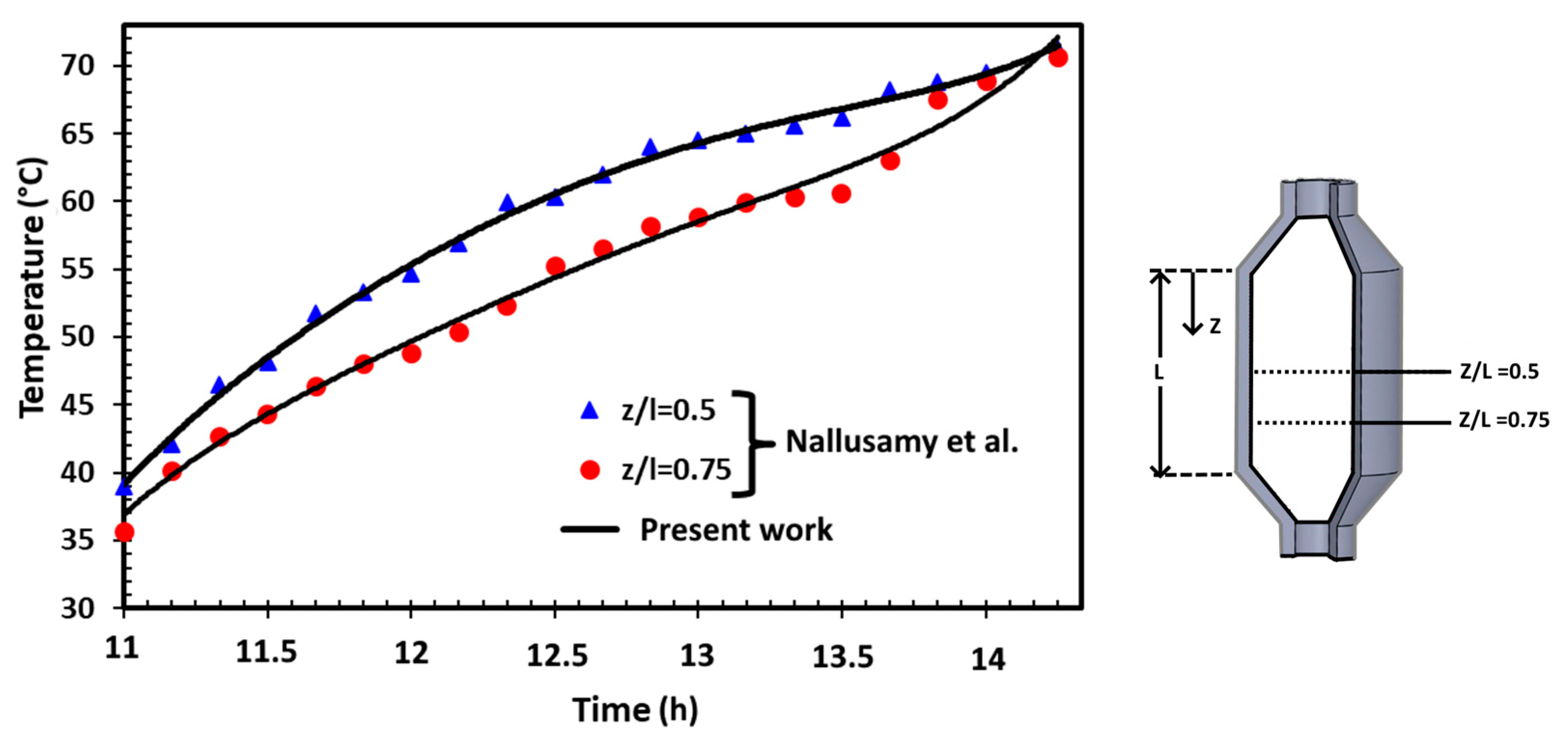
3. Validation and Grid Sensitivity Test

The validation of the numerical code is performed by a direct comparison with the experimental results of Nallusamy et al. [59]. In this study, the authors investigate the behavior of a flat plate solar collector connected to an energy storage tank. This tank is equipped with spherical encapsulated PCM (paraffin). The water feeding mass flow rate is 6 L/min, and the porosity of the incorporated capsules is 0.49.
The temperature histories of the fluid with PCM in two cross-sections of the tank (Z/L = 0.5 and 0.75) are plotted in Figure 3. As shown in the figure, the simulated and experimental results are in good agreement with a maximum error that does not exceed 5.5%.
To guarantee the accuracy of the results, four grids (G1, G2, G3 and G4) were tested. The time needed to reach the target temperature (t70°C) is chosen as a sensitive parameter. The results of the grid sensitivity test are presented in Table 3. Based on the results of this table, it was decided to choose the G3 grid to perform all the numerical simulations. In fact, (t70°C) varies only by (0.12944%) by increasing the grid from 36,857 (G3) to 63,121 (G4). The selected mesh is presented in Figure 4.

4. Results and Discussion

In this section, the effect of nanofluid volume flow rate and CNT volume fraction on the temperature field, fluid flow and melting process will be discussed. The results will be presented for three typical days in December, March, and July considering two configurations corresponding to the presence or absence of baffles.

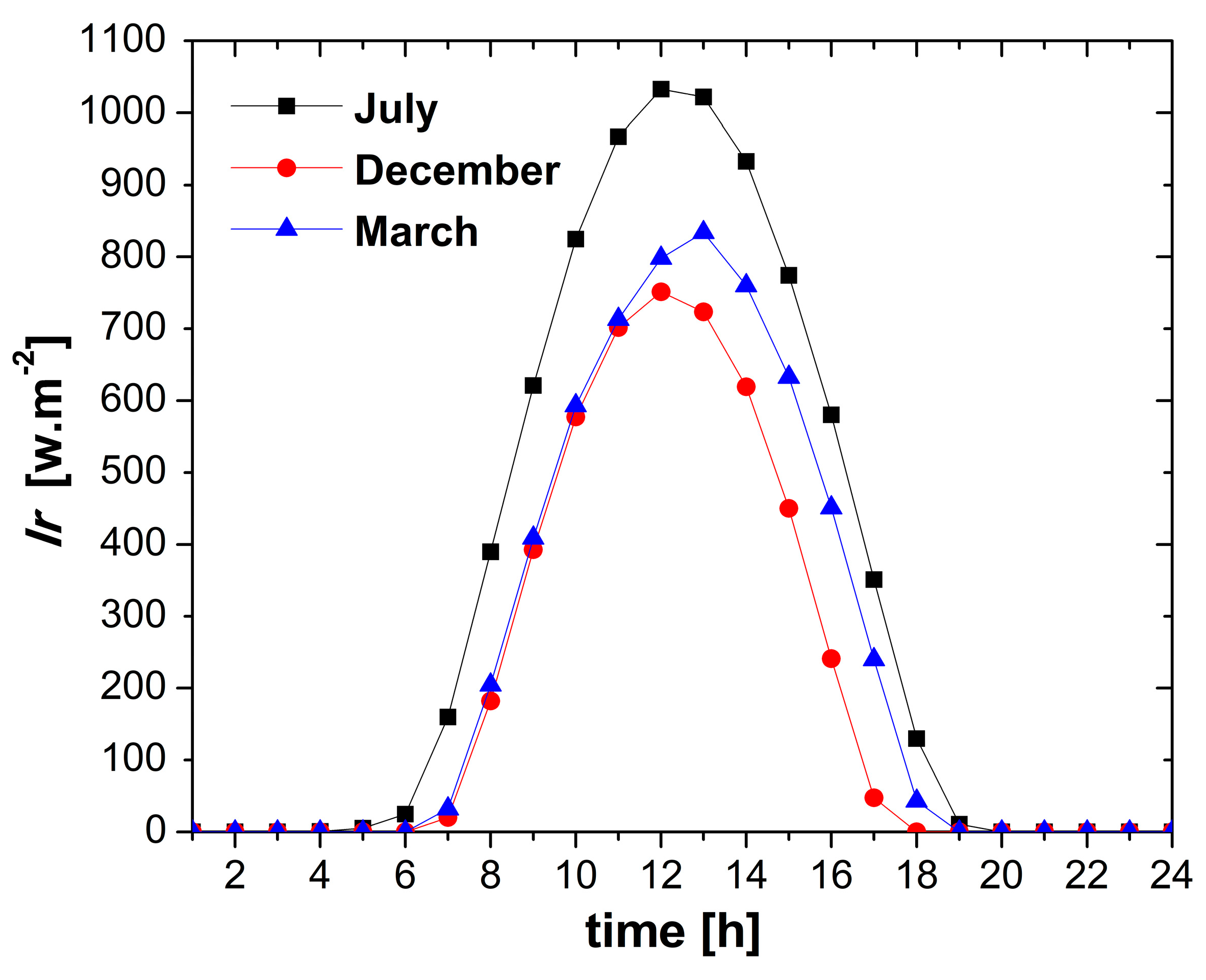
4.1. Weather Conditions

The variation in incident solar radiation for three of the months considered (December, March, and July) is shown in Figure 5. It can be seen that the incident solar radiation increases gradually with time until it reaches its peak value at the middle of the day. After that, it begins to decrease until it reaches its zero value after about 18 h. As expected, the incident solar radiation reaches its maximum value at the summer month (July), followed by the spring month (March), while the minimum value can be found at the winter month (December). This is due to the low elevation angle in winter. Figure 6 illustrates the variation of the ambient temperature with time during the day for the three considered months. The results show that the ambient temperature begins to decrease gradually until time 06:00 in March and July and until time 07:00 in December. After that, it increases until it reaches a maximum value around time 15:00. This behavior can be seen for all selected months. Beyond this hour, it begins to decrease gradually until it reaches its lowest value at the end of the day. Again, the maximum value of the ambient temperature can be found as predicted in July, while the minimum one occurs in December. The variation of the external air velocity with time during the day for three selected months is presented in Figure 7. It is noted that the velocity reaches its peak value in July, while the lowest value of it can be found in December. In general, an oscillatory relation between the velocity and the time can be found in all selected months. Furthermore, in July, there is a continuous increase in the velocity from time 13:00 to time 20:00. However, in March, the period of this increasing in the velocity begins to be less, whereas a sharp decrease is found in December. After time 20:00, the velocity begins to decrease in July, while an opposite trend can be seen in March and December. It is to be mentioned that the presented solar irradiations, ambient temperatures, and air velocities are averaged for each day/hour for each specific month.

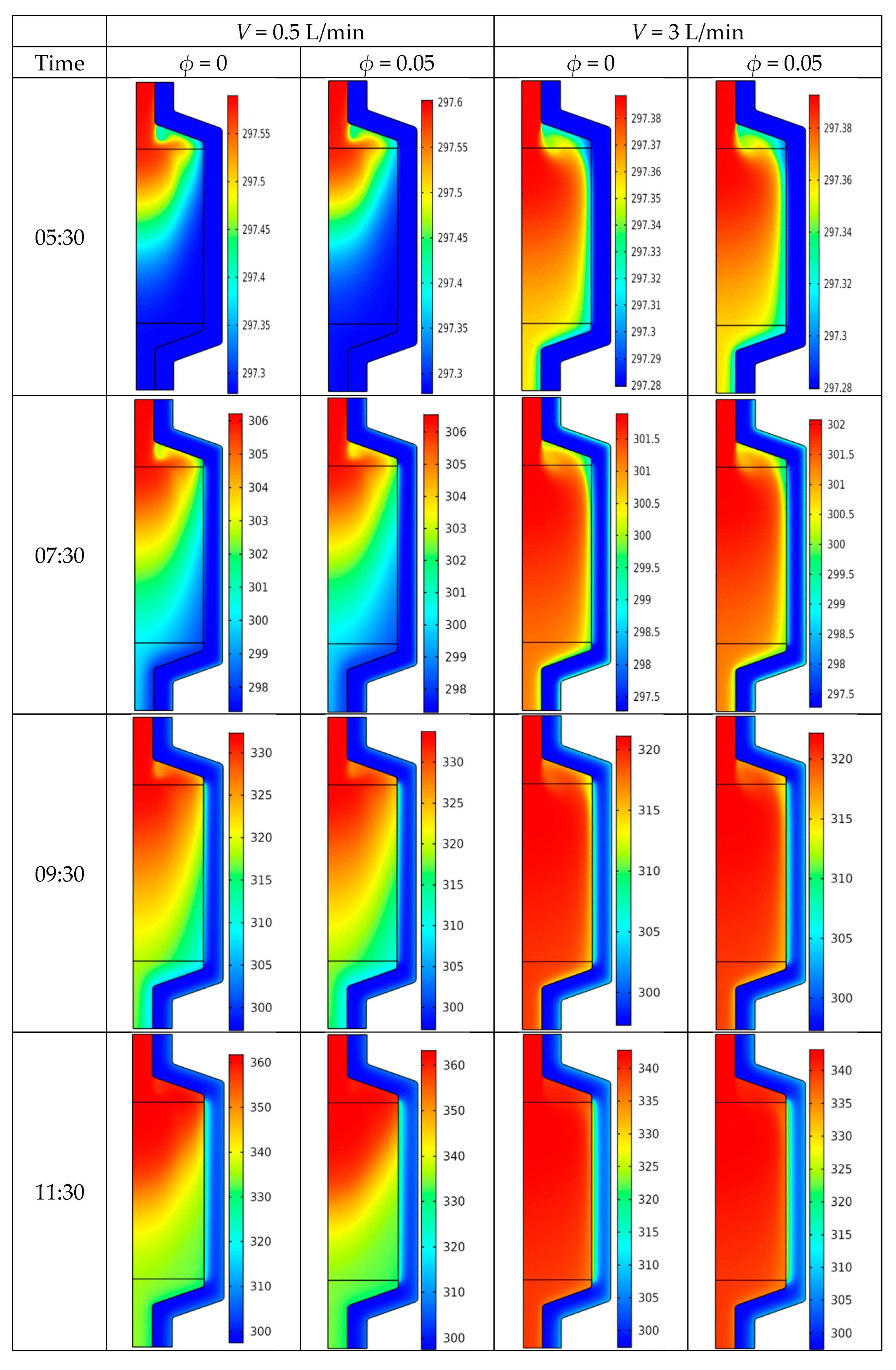
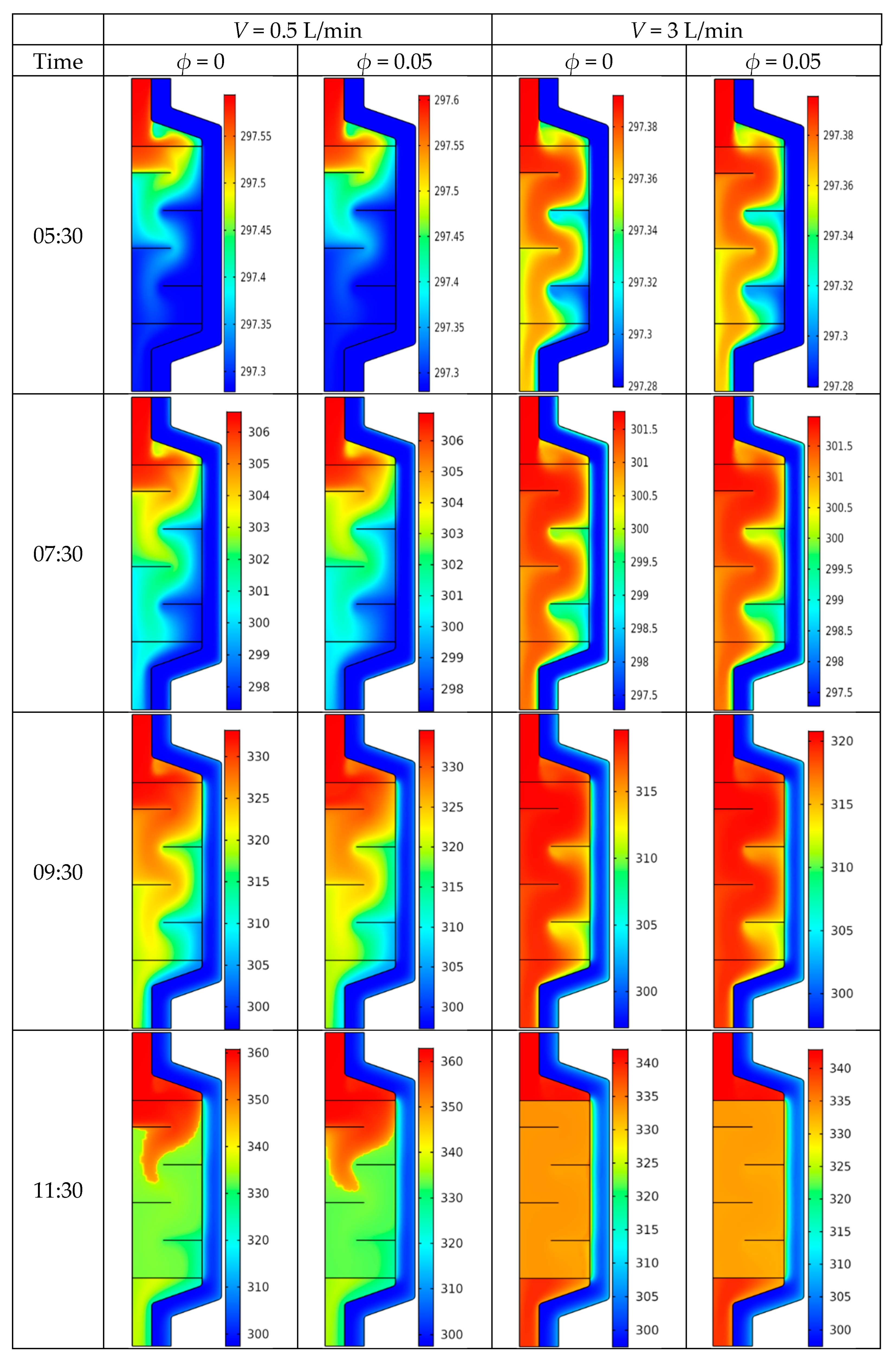
4.2. Temperature Field
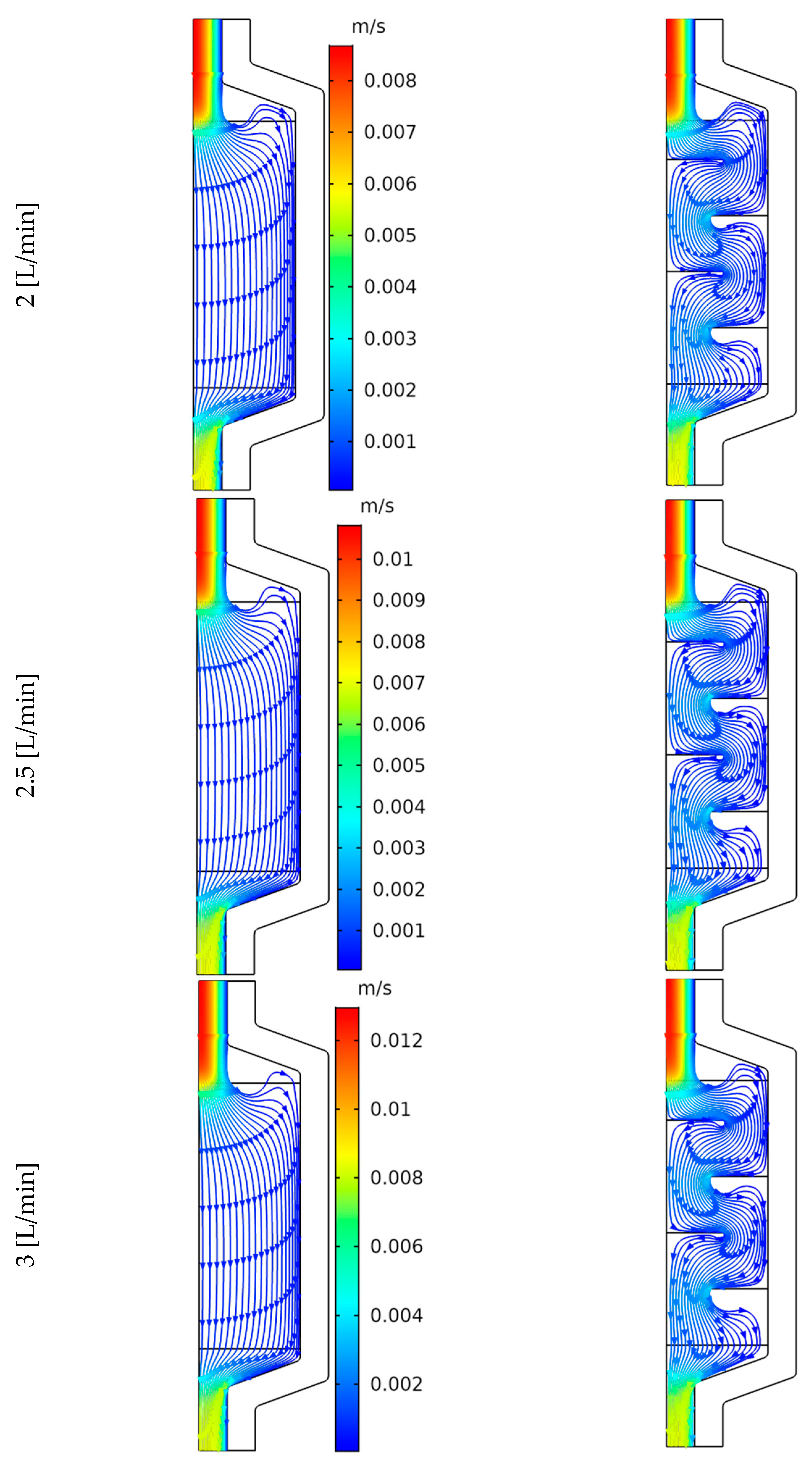
Figure 8 presents the temporal variations of the minimum PCM temperature for the considered months (with and without baffles) at various volume flow rates and CNT volume fractions. It is noticed that for July, due to the high solar irradiance, the target temperature (70 °C) is reached for all the considered volume flow rates and CNT volume fractions. For the month of March, the target temperature approximatively reached 69.85 °C only for V = 0.5 L/min and ϕ = 0.05. For the other volume fractions and volume flow rates it is not reached, but the performance still acceptable since the minimum temperatures at the end of the day are considerably higher than the melting temperature of the PCM (60 °C). The use of baffles has no beneficial effect and causes a reduction in the minimum temperatures. In fact, at the end of the day, there are still some zones in the PCM where the temperatures are lower than the melting point, which indicates the non-completion of the melting process. For December, the minimum temperatures are less than 60 °C for all the considered cases and are lower using the baffles. It is to be mentioned that the variation of temperature occurs principally in three steps: in the first step, the solid PCM gains energy as sensible heat with an increase in the temperature, in the second step, the PCM begins transforming to liquid (phase change at constant temperature), the third step begins when the PCM is transformed to liquid, and it gains the energy at sensible heat again. This third step explains the quick rise of the temperature after the temperature plateau at 60 °C, especially in July, where the solar radiation is higher. It is also to be noted that during December, the PCM is not completely liquid: that is why the third step does not occur.
For July, the target temperature is reached at various times of the days when the working conditions change. For a better understanding of this behavior, Figure 9 presents the effect of the volume fraction and the volume flow rate on the time at which this target temperature is reached (t70°C). First, it is noted that the use of baffles delays the melting process, and for all the corresponding volume fractions and volume flow rate, longer time is needed to reach 70 °C. It is also clear that the use of CNT nanoparticles has a beneficial effect on the heat storage in the PCM tank. In fact, the increase in the CNT volume fraction leads to the reduction in (t70°C), indicating higher performances of the melting process. Concerning the influence of the volume flow rate, an interesting behavior is encountered. In fact, the variation is not monotone, and optimal values appear. In the absence of baffles, the lowest time occurs for V = 2.5 L/min for all volume fractions considered. When baffles are used, the lowest time occurs for V = 2 L/min also for all volume fractions considered, except for φ = 0, where it occurs for V = 2.5 L/min. It is to be mentioned that the existence of this optimum is due to the competition between the increase in the heat transfer coefficient and the reduction in the nanofluid residence time in the tank when the volume flow rate is increased. These results can practically lead to improving the thermal–hydrodynamic performances of the system by reducing the pumping power while promoting the heat transfer process.
Figure 10 shows the temperature field for various times in the PCM energy storage tank (without baffles) during a day of July for various values of the volumetric flow rate and the solid volume fraction. For low volume flow rates (V = 0.5 L/min), it can be seen that in the first hours of the day, the addition of CNT nanoparticles (ϕ = 0.05) does not cause any notable change in the temperature distribution within the tank. This can be confirmed from the high similarity between the temperature fields for both pure water (ϕ = 0) and CNT–water nanofluid (ϕ = 0.05). For lower volume flow rates, higher temperatures occur especially after 13:00, where the solar irradiance is maximal. In addition, the incorporation of a CNT causes an increase in the temperature; this is due to the enhanced properties of the nanofluid. It is also to be mentioned that the temperature increases obviously with time increase. For example, the maximum temperature increases from 24.4 °C, at time 5:30 to 106.85 °C, at time 13:30. The local temperature cannot be an indicator of the performance of the heat storage process: in fact, for low volume flow rates, the maximum temperatures are located only at the entrance of the tank. As mentioned in Section 2, the main goal is to store heat in the PCM storage tank at a minimum local temperature of 70 °C. The time needed to reach this temperature is noted as t70°C. This time is a key indicator of the performance of the charging process. The shorter the t70°C, the faster the charging process. It is noticed that this time is shorter for higher volume flow rates and higher CNT volume fractions, indicating higher performances of the charging process.
For pure water (ϕ = 0), the PCM reaches 70 °C, at time 14:39, while it is reached at time 14:19 for nanofluid (ϕ = 0.05). Using CNT nanoparticles leads to reducing the time of the charging phase of PCM. The difference between the temperature fields at V = 0.5 L/min and V = 3 L/min can be summarized by two points. The first point is that the temperature begins to decrease with increasing V for all values of t and ϕ, whereas the second difference is that the hot temperature zone begins to expand at V = 3 L/min compared to the corresponding zone at V = 0.5 L/min. The main finding from the results presented in Figure 10 is that the minimum time required for PCM to reach 70 °C (i.e., 13:54), corresponds to ϕ = 0.05 and V = 3 L/min.
The temperature distribution in the PCM energy storage tank (with baffles) during a day of July for different values of the volume flow rate and CNT volume fraction is illustrated in Figure 11. Four horizontal straight baffles having equal length are incorporated in the tank. Again, it can be observed that for V = 0.5 L/min, the increase in the solid volume fraction does not alter the pattern of the structure of the temperature field. In addition, it can be mentioned that the temperature gradually increases with time. Regarding the required time to reach 70 °C, the results showed that PCM reaches this degree at time 15:45 when the pure water is used. However, the PCM charging phase finishes at time 15:11 when CNT nanoparticles were added to the water. Concerning the effect of using the internal baffles inside the tank, by comparing the results of Figure 10 and Figure 11, it can be mentioned that the baffles decrease the spreading of the temperature fields inside the tank. This behavior occurs for all the volume fractions considered. Moreover, it can be concluded that the existence of baffles leads to an increase in the time of the PCM charging phase. Thus, the time needed to reach 70 °C is longer with baffles. For example, for pure water at V = 0.5 L/min, the temperature of 70 °C is reached at 15:45 with baffles and at 14:39 without baffles. Meanwhile, for nanofluid, it occurs at 15:11 with baffles and at 14:19 without baffles. It can also be mentioned that the increase in volume flow rate causes important changes in the temperature field. In fact, the zones of hot temperature spread further inside the tank compared to the low volume flow rate case.
The variations of the midline temperature profile along the axial axis for three times of a July day and various CNT volume fractions at (V = 0.5 L/min) are illustrated in Figure 12. Since the thermal non-equilibrium model is considered, both the temperatures of PCM (TPCM) and nanofluid (Tnf) are plotted, and it is obvious that Tnf is higher than TPCM. For all the considered cases, the nanofluid temperature stays quasi-constant until z = 0.18 m, where it meets the PCM capsules and begins to lose heat. After this position, the temperatures of PCM and nanofluid began decreasing uniformly in the absence of baffles and stepwise when baffles are used. It should also be mentioned that the addition of nanoparticles leads to an increase in the temperatures of nanofluid and consequently of PCM. At the outlet of the energy storage tank, the temperature of nanofluid is higher when baffles are used; this indicates that less heat is transferred to the PCM, leading to a lower performance of the melting process. In addition, higher temperature occurs as we move forward in time due to the increase in solar irradiation.

4.3. Flow Structure

The CNT–water flow structure in the energy storage tank with and without baffles at 12:00 for a day of July for various volume flow rates and ϕ = 0.05 is displayed in Figure 13. It can be seen, as expected, that the velocity begins to increase as the values of the volume flow rate increase. In addition, it can be observed that there is a noteworthy difference between the flow structure with and without baffles. For a tank without baffles, the pattern of the flow structure is quasi-unidirectional in the packed bed for all the considered volume flow rates. With respect to the baffle case, the baffles lead to the generation of a bidirectional flow structure by guiding the nanofluid. It is also worth mentioning that the velocity has a maximum value at the inlet and then decreases as it passes through the packed bed.

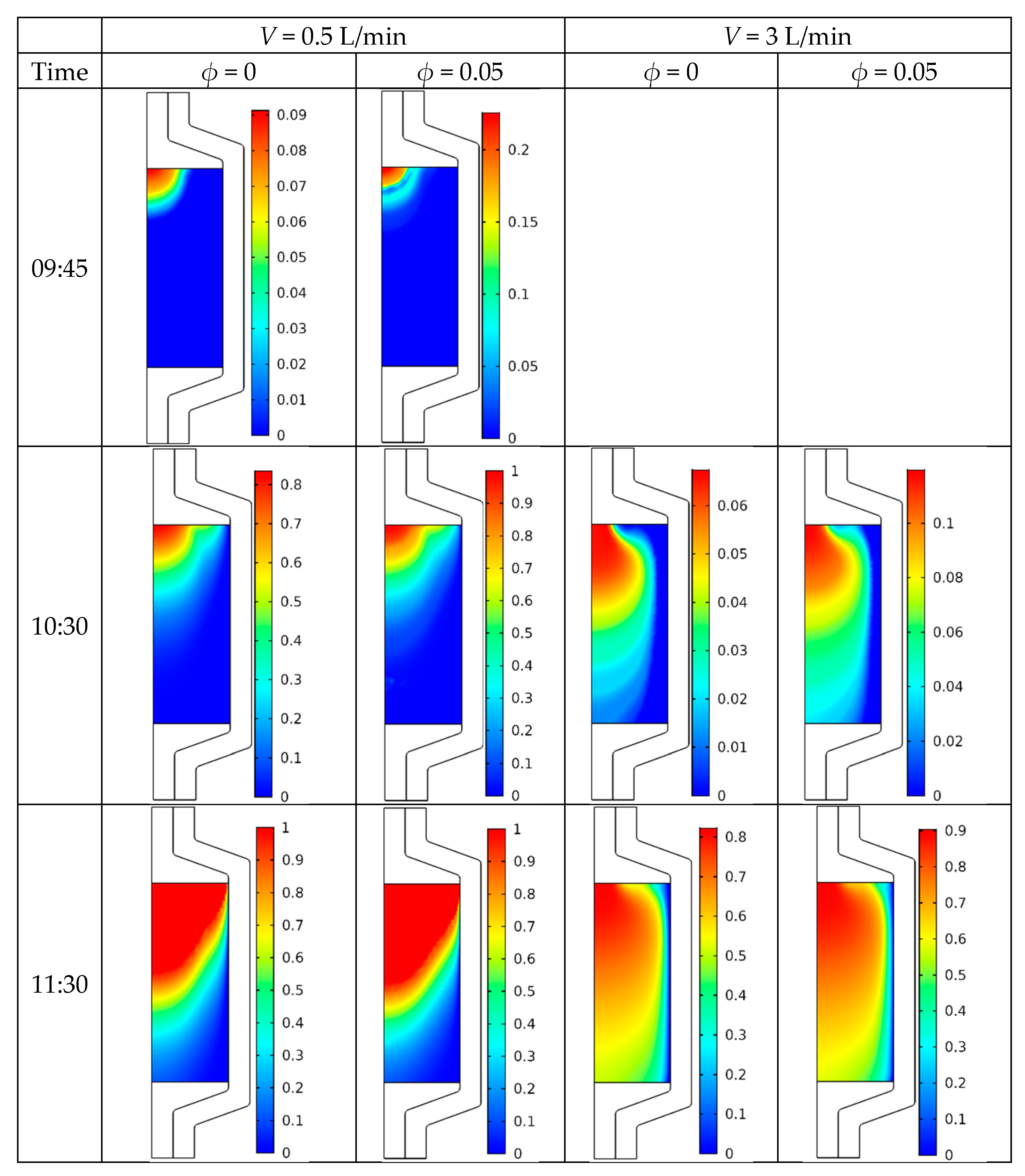
4.4. Melting Process

Figure 14 illustrates the liquid fraction distribution at several times during a July day (without baffles) for various volume flow rates and CNT volume fractions. It should be mentioned that the melting of PCM begins earlier for lower volume flow rates. In fact, it begins at 09:45 for V = 0.5 L/min and 10:30 for V = 3 L/min. Moving forward in time, the local liquid fraction increases especially at the top region of the PCM packed bed. This is confirmed by the temperature fields presented in Figure 10. The use of CNT leads to considerable enhancement of the melting process, and the local liquid fractions are higher compared to the case of pure water. Despite the thermal insulation of the tank, the local liquid fractions values occur at the center of the tank. This is due to the heat exchanged with the surrounding caused by the external air flow.
The time at which all the PCM is transformed to liquid is denoted by tliq and presented at the bottom row. This time is lower for higher volume flow rates and higher CNT volume fractions, indicating a more performant melting process. Similarly, Figure 15 presents the local distribution of the liquid fraction with incorporated baffles under the same conditions as in Figure 14. The same conclusions can be drawn. When comparing the results of Figure 11 and Figure 12, it can be mentioned that the use of baffles opposes the melting process, and the times at which all the PCM is converted to liquid are higher. It is also remarked that the presence of baffles causes higher local liquid fractions at the top region of the packed bed and lower fractions at the bottom region especially at the right corners of the baffles. This result can be explained by the flow structures presented in Figure 13, where it is noticed that the nanofluid does not easily reach the regions delimited by the baffles and the wall of the tank.
The temporal variation of the average liquid fraction for the cases with and without baffles at V = 3 L/min and ϕ = 0.05 are presented in Figure 16. For all the considered months, it is clear that the use of baffles reduces the performance of the melting process. In fact, for July, the time needed to melt all the PCM is delayed by using the baffles, and for December and March, the melting becomes incomplete even at the end of the day. When comparing the temporal variations of the liquid fraction during the three months, it is obvious that the melting process is quicker during July due to the higher solar irradiance.

5. Conclusions

In this paper, the flow field, heat transfer and melting process inside an encapsulated PCM filled heat storge tank working under actual weather conditions were numerically studied. The main conclusions can be summarized as follows:
-
A similar pattern of the temperature distribution inside the PCM energy storage tank was noticed with and without the use of CNT nanofluid.
-
For all the considered cases, the temperature began to increase gradually with time.
-
The increase in the volume flow rate and addition of CNT nanoparticles lead to a reduction in the charging time.
-
The time required to completely transform the PCM to the liquid was reduced by using CNT nanoparticles.
-
The use of baffles opposes the melting process, especially at the corners.
-
The midline nanofluid and PCM temperature profiles was found to decrease along the axial axis.
-
The optimum melting process occurred for V = 2.5 L/min when no baffles were used and for V = 2 L/min when baffles were used.

Author Contributions

Conceptualization, L.K.; Methodology, L.K., A.K.H., W.H., W.R., A.S. and K.R.; Software, L.K. and T.L.; Formal analysis, L.K., A.K.H., W.H., L.B.S., B.A., T.L. and K.R.; Investigation, L.K., L.B.S. and K.R.; Resources, B.A.; Writing—original draft, L.K., A.K.H., W.H., L.B.S., B.A., W.R., T.L., A.S. and K.R.; Writing—review & editing, L.K., A.K.H., W.H., L.B.S., B.A., W.R., A.S. and K.R.; Supervision, B.A.; Project administration, B.A.; Funding acquisition, B.A. and T.L. All authors have read and agreed to the published version of the manuscript.

Funding

This research has been funded by Scientific Research Deanship at the University of Ha’il, Saudi Arabia through project number “RD-21 025”.

Institutional Review Board Statement

Not applicable.

Informed Consent Statement

Not applicable.

Data Availability Statement

Not applicable.

Conflicts of Interest

The authors declare no conflict of interest.

References

  1. Ghodbane, M.; Bellos, E.; Said, Z.; Boumeddane, B.; Hussein, A.K.; Kolsi, L. Evaluating Energy efficiency and economic effect of heat transfer in copper tube for small solar linear Fresnel reflector. J. Therm. Anal. Calorim. 2021, 143, 4197–4215. [Google Scholar] [CrossRef]
  2. Ghodbane, M.; Boumeddane, B.; Hussein, A.K.; Li, D.; Sivasankaran, S. Optical numerical investigation of a solar power plant of parabolic trough collectors. J. Therm. Eng. 2021, 7, 550–569. [Google Scholar] [CrossRef]
  3. Ben Abderrahmane, A.; Benazza, A.; Hussein, A.K. Heat transfer enhancement analysis of tube receiver for parabolic trough solar collector with central corrugated insert. J. Heat Transf.-Trans. ASME 2020, 142, 062001. [Google Scholar] [CrossRef]
  4. Hussein, A.K.; Walunj, A.; Kolsi, L. Applications of nanotechnology to enhance the performance of the direct absorption solar collectors. J. Therm. Eng. 2016, 2, 529–540. [Google Scholar] [CrossRef]
  5. Ghodbane, M.; Boumeddane, B.; Hussein, A.K.; Ali, H.; Li, D. Thermal numerical investigation of a small parabolic trough collector under desert climatic conditions. J. Therm. Eng. 2021, 7, 429–446. [Google Scholar] [CrossRef]
  6. Riahi, S.; Liu, M.; Jacob, R.; Belusko, M.; Bruno, F. Assessment of exergy delivery of thermal energy storage systems for CSP plants: Cascade PCMs, graphite-PCMs and two-tank sensible heat storage systems. Sustain. Energy Technol. Assess. 2020, 42, 100823. [Google Scholar] [CrossRef]
  7. Elfeky, K.; Li, X.; Ahmed, N.; Lu, L.; Wang, Q. Optimization of thermal performance in thermocline tank thermal energy storage system with the multilayered PCM(s) for CSP tower plants. Appl. Energy 2019, 243, 175–190. [Google Scholar] [CrossRef]
  8. Li, D.; Li, Z.; Zheng, Y.; Liu, C.; Hussein, A.K.; Liu, X. Thermal performance of a PCM-filled double-glazing unit with different thermophysical parameters of PCM. Sol. Energy 2016, 133, 207–220. [Google Scholar] [CrossRef] [Green Version]
  9. Liu, C.; Wu, Y.; Li, D.; Ma, T.; Hussein, A.K.; Zhou, Y. Investigation of thermal and optical performance of a phase change material filled double-glazing unit. J. Build. Phys. 2018, 42, 99–119. [Google Scholar] [CrossRef]
  10. Mao, Q.; Zhang, Y. Thermal energy storage performance of a three-PCM cascade tank in a high-temperature packed bed system. Renew. Energy 2020, 152, 110–119. [Google Scholar] [CrossRef]
  11. Galione, P.; Pérez-Segarra, C.; Rodriguez, I.; Torras, S.; Rigola, J. Numerical evaluation of multi-layered solid-PCM thermocline-like tanks as thermal energy storage systems for CSP applications. Energy Procedia 2015, 69, 832–841. [Google Scholar] [CrossRef] [Green Version]
  12. Li, Y.; Zhang, N.; Ding, Z. Investigation on the energy performance of using air-source heat pump to charge PCM storage tank. J. Energy Storage 2020, 28, 101270. [Google Scholar] [CrossRef]
  13. Fang, Y.; Niu, J.; Deng, S. An analytical technique for the optimal designs of tube-in-tank thermal energy storage systems using PCM. Int. J. Heat Mass Transf. 2019, 128, 849–859. [Google Scholar] [CrossRef]
  14. Saw, C.; Al-Kayiem, H.; Aris, M. Experimental investigation on the performance of integrated PCM-flat plate solar collector. J. Appl. Sci. 2012, 12, 2390–2396. [Google Scholar]
  15. Sharma, S.; Micheli, L.; Chang, W.; Tahir, A.; Reddy, K.; Mallick, T. Nano-enhanced phase change material for thermal management of BICPV. Appl. Energy 2017, 208, 719–733. [Google Scholar] [CrossRef]
  16. Karthikeyan, S.; Solomon, G.; Kumaresan, V.; Velraj, R. Parametric studies on packed bed storage unit filled with PCM encapsulated spherical containers for low temperature solar air heating applications. Energy Convers. Manag. 2014, 78, 74–80. [Google Scholar] [CrossRef]
  17. Abdelsalam, M.; Sarafraz, P.; Cotton, J.; Lightstone, M. Heat transfer characteristics of a hybrid thermal energy storage tank with phase change materials (PCMs) during indirect charging using isothermal coil heat exchanger. Sol. Energy 2017, 157, 462–476. [Google Scholar] [CrossRef]
  18. Delgado, M.; Lazaro, A.; Mazo, J.; Penalosa, C.; Marin, J.; Zalba, B. Experimental analysis of a coiled stirred tank containing a low cost PCM emulsion as a thermal energy storage system. Energy 2017, 138, 590–601. [Google Scholar] [CrossRef]
  19. Meng, Z.; Zhang, P. Experimental and numerical investigation of a tube-in-tank latent thermal energy storage unit using composite PCM. Appl. Energy 2017, 190, 524–539. [Google Scholar] [CrossRef]
  20. Bouhal, T.; El- Rhafiki, T.; Kousksou, T.; Jamil, A.; Zeraouli, Y. PCM addition inside solar water heaters: Numerical comparative approach. J. Energy Storage 2018, 19, 232–246. [Google Scholar] [CrossRef]
  21. Huang, H.; Wang, Z.; Zhang, H.; Dou, B.; Huang, X.; Liang, H.; Goula, M. An experimental investigation on thermal stratification characteristics with PCMs in solar water tank. Sol. Energy 2019, 177, 8–21. [Google Scholar] [CrossRef]
  22. Mousa, H.; Naser, J.; Houche, O. Using PCM as energy storage material in water tanks: Theoretical and experimental investigation. J. Energy Storage 2019, 22, 1–7. [Google Scholar] [CrossRef]
  23. Lee, Y.; Kim, M.; Lee, S.; Gim, J.; Chung, J. Numerical analysis in a full-scale thermal energy storage tank with dual PCM capsules. Energy Build. 2019, 204, 109410. [Google Scholar] [CrossRef]
  24. Huang, H.; Xiao, Y.; Lin, J.; Zhou, T.; Liu, Y.; Zhao, Q. Improvement of the efficiency of solar thermal energy storage systems by cascading a PCM unit with a water tank. J. Clean. Prod. 2020, 245, 118864. [Google Scholar] [CrossRef]
  25. Carmona, M.; Rincon, A.; Gulfo, L. Energy and exergy model with parametric study of a hot water storage tank with PCM for domestic applications and experimental validation for multiple operational scenarios. Energy Convers. Manag. 2020, 222, 113189. [Google Scholar] [CrossRef]
  26. Saw, C.; Al-Kayiem, H.; Owolabi, A. Experimental investigation on the effect of PCM and nano-enhanced PCM of integrated solar collector performance. WIT Trans. Ecol. Environ. 2013, 179, 899–909. [Google Scholar] [CrossRef] [Green Version]
  27. Al-Kayiem, H.; Lin, S. Performance evaluation of a solar water heater integrated with a PCM nanocomposite TES at various inclinations. Sol. Energy 2014, 109, 82–92. [Google Scholar] [CrossRef]
  28. Xiao, X.; Zhang, P.; Li, M. Experimental and numerical study of heat transfer performance of nitrate/expanded graphite composite PCM for solar energy storage. Energy Convers. Manag. 2015, 105, 272–284. [Google Scholar] [CrossRef]
  29. Mahdi, J.; Nsofor, E. Solidification of a PCM with nanoparticles in triplex-tube thermal energy storage system. Appl. Therm. Eng. 2016, 108, 596–604. [Google Scholar] [CrossRef]
  30. Lin, S.; Al-Kayiem, H. Evaluation of copper nanoparticles—Paraffin wax compositions for solar thermal energy storage. Sol. Energy 2016, 132, 267–278. [Google Scholar] [CrossRef]
  31. Kant, K.; Shukla, A.; Sharma, A.; Biwole, P. Heat transfer study of phase change materials with graphene nano particle for thermal energy storage. Sol. Energy 2017, 146, 453–463. [Google Scholar] [CrossRef]
  32. Mandal, S.; Kumar, S.; Singh, P.; Mishra, S.; Bishwakarma, H.; Choudhry, N.; Nayak, R.; Das, A. Performance investigation of CuO-paraffin wax nanocomposite in solar water heater during night. Thermochim. Acta 2019, 671, 36–42. [Google Scholar] [CrossRef]
  33. Kumar, P.; Mylsamy, K. A comprehensive study on thermal storage characteristics of nano-CeO2 embedded phase change material and its influence on the performance of evacuated tube solar water heater. Renew. Energy 2020, 162, 662–676. [Google Scholar] [CrossRef]
  34. Mandal, S.; Kumar, S.; Singh, P.; Mishra, S.; Singh, D. Performance investigation of nanocomposite based solar water heater. Energy 2020, 198, 117295. [Google Scholar] [CrossRef]
  35. Kumar, P.; Mylsamy, K.; Alagar, K.; Sudhakar, K. Investigations on an evacuated tube solar water heater using hybrid-nano based organic phase change material. Int. J. Green Energy 2020, 17, 872–883. [Google Scholar] [CrossRef]
  36. Al-Jethelah, M.; Tasnim, S.; Mahmud, S.; Dutta, A. Nano-PCM filled energy storage system for solar-thermal applications. Renew. Energy 2018, 126, 137–155. [Google Scholar] [CrossRef]
  37. Saw, C.; Al-Kayiem, H. Thermophysical properties of nano-phase change material composition for thermal energy storage. Appl. Mech. Mater. 2012, 232, 127–131. [Google Scholar]
  38. Owolabi, A.; Al-Kayiem, H.; Baheta, A. Nanoadditives induced enhancement of the thermal properties of paraffin-based nanocomposites for thermal energy storage. Sol. Energy 2016, 135, 644–653. [Google Scholar] [CrossRef]
  39. Sheikholeslami, M. Numerical simulation for solidification in a LHTESS by means of nano-enhanced PCM. J. Taiwan Inst. Chem. Eng. 2018, 86, 25–41. [Google Scholar] [CrossRef]
  40. Harikrishnan, S.; Devaraju, A.; Kumar, G.; Kalaiselvam, S. Improved thermal energy storage behavior of a novel nanofluid as phase change material (PCM). Mater. Today Proc. 2019, 9, 410–421. [Google Scholar] [CrossRef]
  41. Dawood, M.; Nabil, T.; Kabeel, A.; Shehata, A.; Abdalla, A.; Elnaghi, B. Experimental study of productivity progress for a solar still integrated with parabolic trough collectors with a phase change material in the receiver evacuated tubes and in the still. J. Energy Storage 2020, 32, 102007. [Google Scholar] [CrossRef]
  42. Naghdbishi, A.; Yazdi, M.; Akbari, G. Experimental investigation of the effect of multi-wall carbon nano tube—Water/glycol based nanofluids on a PVT system integrated with PCM covered collector. Appl. Therm. Eng. 2020, 178, 115556. [Google Scholar] [CrossRef]
  43. Ji, C.; Qin, Z.; Dubey, S.; Choo, F.; Duan, F. Simulation on PCM melting enhancement with double-fin length arrangements in a rectangular enclosure induced by natural convection. Int. J. Heat Mass Transf. 2018, 127, 255–265. [Google Scholar] [CrossRef]
  44. Gharebaghi, M.; Sezai, I. Enhancement of heat transfer in latent heat storage modules with internal fins. Numer. Heat Transf. Part A Appl. 2007, 53, 749–765. [Google Scholar] [CrossRef]
  45. Touati, B.; Kerroumi, N.; Virgone, J. Solar thermal energy discharging from a multiple phase change materials storage tank. Appl. Sol. Energy 2017, 53, 185–189. [Google Scholar] [CrossRef]
  46. Sathe, T.; Dhoble, A. Thermal analysis of an inclined heat sink with finned PCM container for solar applications. Int. J. Heat Mass Transf. 2019, 144, 118679. [Google Scholar] [CrossRef]
  47. Gürtürk, M.; Kok, B. A new approach in the design of heat transfer fin for melting and solidification of PCM. Int. J. Heat Mass Transf. 2020, 153, 119671. [Google Scholar] [CrossRef]
  48. Singh, R.; Xu, H.; Kaushik, S.; Rakshit, D.; Romagnoli, A. Effective utilization of natural convection via novel fin design and influence of enhanced viscosity due to carbon nano-particles in a solar cooling thermal storage system. Sol. Energy 2019, 183, 105–119. [Google Scholar] [CrossRef]
  49. Mousavi, S.; Siavashi, M.; Heyhat, M. Numerical melting performance analysis of a cylindrical thermal energy storage unit using nano-enhanced PCM and multiple horizontal fins. Numer. Heat Transf. Part A Appl. 2019, 75, 560–577. [Google Scholar] [CrossRef]
  50. Foudhil, W.; Dhifaoui, B.; Jabrallah, S.B.; Dutil, Y.; Rousse, D.R. Numerical simulation of thermal storage by latent and sensible heat in a porous vertical channel: Performance analysis and comparison. Numer. Heat Transf. Part A Appl. 2012, 62, 948–972. [Google Scholar] [CrossRef]
  51. Nield, D.; Bejan, A. Convection in Porous Media, in Convection Heat Transfer; John Wiley & Sons, Inc.: Hoboken, NJ, USA, 2013. [Google Scholar]
  52. Wakao, N.; Kaguei, S.; Funazkri, T. Effect of fluid dispersion coefficients on particle-to fluid heat transfer coefficients in packed beds: Correlation of Nusselt numbers. Chem. Eng. Sci. 1979, 34, 325–336. [Google Scholar] [CrossRef]
  53. Sheikholeslami, M.; Bandpy, M.; Ashorynejad, H. Lattice Boltzmann method for simulation of magnetic field effect on hydrothermal behavior of nanofluid in a cubic cavity. Phys. A 2015, 432, 58–70. [Google Scholar] [CrossRef]
  54. Sajjadi, H.; Amiri Delouei, A.; Atashafrooz, M.; Sheikholeslami, M. Double MRT Lattice Boltzmann simulation of 3D MHD natural convection in a cubic cavity with sinusoidal temperature distribution utilizing nanofluid. Int. J. Heat Mass Transf. 2018, 126, 489–503. [Google Scholar] [CrossRef]
  55. Kolsi, L.; Oztop, H.; Ghachem, K.; Al-Meshaal, M.; Mohammed, H.; Babazadeh, H.; Abu-Hamdeh, N. Numerical study of periodic magnetic field effect on 3D natural convection of MWCNT–water/nanofluid with consideration of aggregation. Processes 2019, 7, 957. [Google Scholar] [CrossRef] [Green Version]
  56. Reddy, J. An Introduction to the Finite Element Method; McGraw-Hill: New York, NY, USA, 1993. [Google Scholar]
  57. Basak, T.; Roy, S.; Babu, S.K.; Pop, I. Finite element simulations of natural convection flow in an isosceles triangular enclosure filled with a porous medium: Effects of various thermal boundary conditions. Int. J. Heat Mass Transf. 2008, 51, 2733–2741. [Google Scholar] [CrossRef]
  58. Basak, T.; Ayappa, K.G. Influence of internal convection during microwave thawing of cylinders. AIChE J. 2001, 47, 835–850. [Google Scholar] [CrossRef]
  59. Nallusamy, N.; Sampath, S.; Velraj, R. Study on performance of a packed bed latent heat thermal energy storage unit integrated with solar water heating system. J. Zhejiang Univ.-Sci. A 2006, 7, 1422–1430. [Google Scholar] [CrossRef]
Figure 1. (a) Studied configurations, (b) weather station at University of Ha’il (Saudi Arabia).
Mathematics 11 01057 g001
Figure 2. Numerical methodology flow chart.
Mathematics 11 01057 g002
Figure 3. Temperature histories during the charging process (V = 6 L/min and ε = 0.49); comparison with the experimental results of Nallusamy et al. [59].
Mathematics 11 01057 g003
Figure 4. Used Mesh.
Mathematics 11 01057 g004
Figure 5. Temporal variation of the incident solar radiation for the three considered months.
Mathematics 11 01057 g005
Figure 6. Temporal variation of the ambient temperature for the three considered months.
Mathematics 11 01057 g006
Figure 7. Temporal variation of the external air velocity for the three considered months.
Mathematics 11 01057 g007
Figure 8. Temporal variations of the minimum PCM temperature for various volume flow rates and CNT volume fractions: (a) July without baffles, (b) July with baffles, (c) March without baffles, (d) March with baffles, (e) December without baffles, (f) December with baffles.
Mathematics 11 01057 g008aMathematics 11 01057 g008b
Figure 9. Effect of the volume flow rate on t70°C for various CNT volume fractions during a day of July: (a) without baffles and (b) with baffles.
Mathematics 11 01057 g009
Figure 10. Temperature field (without baffles) during a July day for various volume flow rates and CNT volume fractions.
Mathematics 11 01057 g010aMathematics 11 01057 g010b
Figure 11. Temperature field (with baffles) during a July day for various volume flow rates and CNT volume fractions.
Mathematics 11 01057 g011aMathematics 11 01057 g011b
Figure 12. The variation of the midline temperature profiles along the axial axis with and without baffles for a July day at V = 0.5 L/min and various CNT volume fraction; (a) t = 09:00; (b) t = 11:00; (c) t = 13:00.
Mathematics 11 01057 g012
Figure 13. Flow structures in the energy storage tank with (right column) and without (left column) baffles at time 12:00 and ϕ = 0.05 for a day of July and various values of the volume flow rates.
Mathematics 11 01057 g013aMathematics 11 01057 g013b
Figure 14. Liquid fraction distributions in PCM packed bed without baffles during a July day for various values of the volume flow rates and CNT volume fractions.
Mathematics 11 01057 g014aMathematics 11 01057 g014b
Figure 15. Liquid fraction distributions in PCM packed bed with baffles during a July day for various values of the volume flow rates and CNT volume fractions.
Mathematics 11 01057 g015aMathematics 11 01057 g015bMathematics 11 01057 g015c
Figure 16. Temporal variation of the average liquid fraction for the considered months (with and without baffles) at V = 3 L/min and ϕ = 0.05.
Mathematics 11 01057 g016
Table 1. Paraffin thermophysical properties [50].
Material PropertySolid ParaffinLiquid Paraffin
Melting temperature, Tm (°C)60-
Latent heat of fusion, L (kJ kg−1)213-
Heat capacity, Cp (J kg−1·K−1)18512384
Density, ρ (kg.m−3)861778
Thermal conductivity, k (W m−1 K−1)0.40.15
Table 2. Properties of water and CNT [55].
WaterCNT
Specific heat, Cp (J kg−1 K−1)4179796
Density, ρ (kg.m−3)997.11600
Thermal conductivity, λ (W m−1 K−1)0.6133000
Thermal expansion coefficient, β (K−1)21 × 10−54.2 × 10−5
Dynamic viscosity, μ (Pa s)0.85 × 10⁻³-
Table 3. Grid sensitivity test: without baffles, V = 3 L/min and ϕ = 0.05.
Number of Elementst70°CVariation (%)Incremental Variation (%)
G1: 779014:07--
G2: 1550213:590.85694-
G3: 3685713:541.515580.66433
G4: 6312113:531.643060.12944
Disclaimer/Publisher’s Note: The statements, opinions and data contained in all publications are solely those of the individual author(s) and contributor(s) and not of MDPI and/or the editor(s). MDPI and/or the editor(s) disclaim responsibility for any injury to people or property resulting from any ideas, methods, instructions or products referred to in the content.

