Abstract
Brushless synchronous homopolar machines (SHM) have long been used as highly reliable motors and generators with an excitation winding on the stator. However, a significant disadvantage that limits their use in traction applications is the reduced specific torque due to the incomplete use of the rotor surface. One possible way to improve the torque density of SHMs is to add inexpensive ferrite magnets in the rotor slots. This paper presents the results of optimizing the performances of an SHM with ferrite magnets for a subway train, considering the timing diagram of train movement. A comparison of its characteristics with an SHM without permanent magnets is also presented. When using the SHM with ferrite magnets, a significant reduction in the dimensions and weight of the motor, as well as power loss, is shown.
Keywords:
ferrite magnets; synchronous homopolar motor; electrically excited synchronous motor; Nelder–Mead method; optimal design of electric machines; subway train; constant power speed range; traction drive MSC:
00A06
1. Introduction
Interior rare-earth permanent magnet synchronous motors (PMSM) are a popular choice in electric vehicle drives of various power ratings. As they have no excitation winding and, consequently, excitation loss, these motors have high power density and efficiency [1,2]. However, their drawbacks are: (1) Rare-earth magnets required in the PMSMs production are expensive and their cost can vary by several times in a year or two because of a limited number of manufacturers; it also makes it inevitable to rely on a limited number of magnet suppliers in the world market [3,4,5]; (2) The rare-earth elements extraction is not environmentally friendly [6]; (3) Strong magnetic field and high temperature in PMSMs with high power density can result in rare-earth magnets demagnetization; (4) If a wide constant power speed region is required, achieving high efficiency at speeds close to maximum is not so easy because of increased winding losses in field weakening mode [7,8,9]; (5) In addition, in electric drives such as drives of subway and railway trains, a large value of uncontrolled electromotive force (EMF) in the windings during rotation of the PMSM creates a fire hazard in the event of an emergency short circuit. Since trains have high inertia and cannot stop quickly in the event of an emergency short circuit, the use of PMSM in this application should be avoided.
Wound rotor synchronous motors (WRSM) have no disadvantages such as this and are used in traction applications by BMW (BMW iX3 crossover) and Renault (Renault Zoe supermini electric car, Fluence sedan, Megane E-TECH small family car) (BMW [10,11], Renault [12]). WRSMs have no magnets. Excitation current as well as demagnetizing part of stator current can be reduced at high speed, which makes it possible to achieve high efficiency throughout a wide constant power speed region [13,14]. However, slip rings in the WRSM design limit the motor speed and reduce its reliability [14].
Homopolar machines (SHM) combine the advantages of PMSMs and WRSMs: they have no slip rings such as PMSMs. Similar to WRSMs, they have no magnets and can have a wide constant power speed range due to controlling the excitation current. An additional advantage of SHM over WRSMs is that the number of the excitation coils does not depend on the number of poles, while it grows with the number of poles in WRSMs, reducing excitation magnetomotive force (MMF).
In the SHM design considered in this paper, there is only one excitation coil. This results in a decrease in the mass and the loss in excitation winding in SHMs compared with those of WRSMs. Also, since there are no losses in the SHM rotor, no rotor cooling is required. There are many applications of SHMs as high-reliable generators: in passenger railway cars, in ships and aircraft [15,16], in welding units [17], and as automotive generators [18].
Applications of SHMs as a traction motor of a mining truck are discussed in [7,19,20,21,22,23]. In [19], the computation method of the traction SHM, based on the set of 2D magnetostatic was described and verified in the experiment in [19]. The control strategy for traction SHMs was described in [20]. The examples of the optimization of the SHM for traction applications based on Nelder–Mead algorithm and the model described in [19] are provided in [21]. Paper [7] provide a comparison of the SHM and PMSM characteristics in the mining truck application.
However, as shown in [23], traction SHMs have the following disadvantages compared to WRSMs: (1) The mass and dimensions of SHMs are greater than those of WRSMs, since each rotor tooth covers approximately one pole pitch, and about half of the pole pitches of the SHMs is not used; (2) SHMs require a higher inverter power rating than WRSMs.
There are multi-pole SHMs with an excitation winding on the stator and rare-earth magnets in the rotor slots [24,25,26]. Such SHMs with rare-earth magnets in the rotor slots are superior to SHMs without permanent magnets due to the better use of the rotor surface, and their weight and dimensions are close to conventional PMSM. The main advantage of SHMs with rare earth magnets, compared to conventional PMSM in traction drives with a wide constant power speed range (CPSR): the inverter utilization is higher, and the cost and rated power of the inverter are lower, since due to the excitation winding, it is possible to set the optimal excitation flux in a wide range of speeds. Thus, the excitation winding current is an additional control signal that expands the opportunities for optimizing the operation of the SHM with magnets. The main disadvantage of the SHM with rare earth magnets, which limits their use, is the high cost of rare earth magnets and raw material dependence on a limited number of suppliers of rare earth elements. In addition, the depth of the rotor slots of the SHM with rare earth magnets is much smaller than that of the SHM without magnets, which worsens the saliency of the rotor of the SHM with rare earth magnets. Therefore, although the use of rare earth magnets creates a significant additional torque, the main torque generated by the interaction of the field of the excitation winding modulated by rotor stacks and the field of the stator winding is reduced.
Further improvement of the characteristics of SHMs with magnets is possible by using inexpensive ferrite magnets in their design. Ferrite magnets are much cheaper than rare-earth ones and produced in many countries throughout the world [5].
An SHM with ferrite magnets is presented in [15,27] as an undercar generator for railway passenger cars. It is shown that the use of SHMs with ferrite magnets has the following main advantages compared to SHMs without magnets: (1) The reduction of the weight and dimensions of the machine; (2) Power loss reduction. However, the review of the literature shows that traction SHMs with ferrite magnets in the rotor slots have not been studied in detail. This article presents a novel design of the traction SHM with ferrite magnets. An example of the optimal design of the SHM with ferrite magnets for the subway train is provided. A comparison between the SHM with ferrite magnets and the SHM without magnets in the target application is also presented. The characteristics of the SHM without magnets for comparison are adopted from our previous study [28].
This study provides the optimization of the SHM with ferrite magnets for subway trains by means of the Nelder–Mead method and the mathematical model described in [19]. The Nelder–Mead method is a one-criterion, unconstrained, local optimum search method. The optimization is based on several criteria such as the minimization of losses, and the armature winding current. The merits of these criteria are chosen and taken into account at building up the cost function. Using the Nelder–Mead method significantly reduces computational efforts compared with multicriteria or global search methods [29,30,31,32,33].
2. Main Design Parameters of the SHM
Figure 1 illustrates the design of the traction motor in question. Its specifications are shown in Table 1. Two stator lamination stacks with 60 teeth and a nonmagnetic supporting core are installed in the housing made of ferromagnetic non-laminated structural steel. Common 8-pole 3-phase armature winding is installed between the teeth of the stator stacks. The rotor stacks are installed opposite the stator stacks, on the shaft using an intermediate sleeve made of ferromagnetic non-laminated structural steel.

Figure 1.
SHM feature representation: (a) 1/4 cross-section and stator armature winding layout; (b) 3D cutout view. A 1/2 stator cutout is shown. The rotor is shown without cutout. The stator winding is not shown to avoid cluttering up the figure.

Table 1.
Technical specifications of the SHM.
A supporting core fixes an excitation winding between the stator and rotor stack pairs. The rotor stacks are rotated with respect to each other by 180 electrical degrees (45 mechanical degrees).
As can be seen in Figure 2, the power supply circuit for the SHM consists of an ordinary three phase invertor to supply the multiphase armature winding and a chopper to supply the excitation winding.
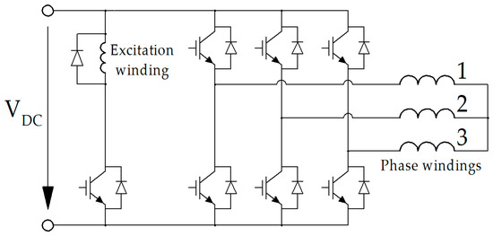
Figure 2.
Diagram of a three-phase inverter with a DC breaker for the excitation winding, where ‘1,2,3’ are numbers of the phases of the SHM armature winding.
3. Representation of the Train Flow Pattern in the Motor Optimization Routine
There are following stages in the motion of the subway train between stations from one station to another, as shown in Figure 3 [34]:
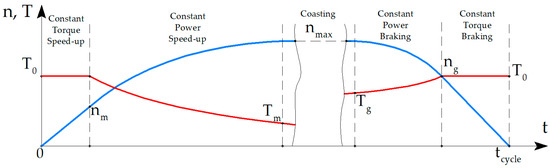
Figure 3.
Sketch of the speed (blue) and torque (red) profiles in time of the traction motor of the subway train.
- It accelerates with the constant torque T0 = 1240 N·m, achieving speed nm = 1427 rpm;
- Continues acceleration with the constant mechanical power until the maximum speed nmax = 4280 rpm is achieved;
- Then it sustains the constant speed or decelerates slowly;
- Brakes with the constant power to the speed ng = 2854 rpm;
- Braking with the constant torque T0 to the stop.
The required torque dependence on the rotational speed is shown in Figure 4. To depict this dependence in the motor and generator modes, there are two abscissa axes. The first abscissa axis directed to the right is for the motor mode, and the second one directed to the left is for the generator mode. Let’s list the specific modes used in the optimization procedure, in order of increasing torque:
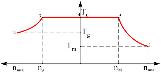
Figure 4.
Demanded speed-torque curve of the subway traction drive.
- Driving mode at the maximum speed nmax;
- Braking mode at the maximum speed nmax;
- Braking mode joining the constant power and constant torque modes;
- Zero speed mode with the maximum torque T0;
- Driving mode joining constant torque and constant power at the speed nm = 1427 rpm.
According to the technical assignment for the motor, the braking mode torque is equal to the motor torque, and ng is twice as large as nm. So, maximum (constant) power in the generator mode is twice as large as in motor mode.
DC catenary voltage is VDC rated = 750 V. Supercapacitors are installed in the train invertor. They charge at braking up to the voltage VDC max = 1050 V. The energy used in supercapacitors is used for the acceleration in the next cycle. Also, during the braking, supercapacitors provide a DC voltage higher than VDC rated, which facilitates implementing brake modes.
4. Average Electrical Loss Calculation
The average of electrical loss over the cycle, that is over the trip from station to station, is estimated with the following assumptions:
- The subway stations are close to each other. The cruising time is excluded from the average loss calculation routine;
- The train accelerates and decelerates only due to the torque produced by the motor. Slopes, windage friction, the friction in the gearbox, etc., are neglected;
- Linear dependence of the losses on speed is assumed at each stage of the cycle.
The average electrical losses <Ploss el> can be calculated as the weighted average of electrical losses Ploss el_i in the operating points of the cycle:
where wi is a normalized weight coefficient defined by the cycle parameters as follows:
The detailed derivation of (1) is given in [28]. The average of any other value can be found in this way if a linear approximation of its dependance on stages of the cycle is assumed.
5. Voltage Limit
The maximum allowed line-to-line voltage in i-th operation point Vi is approximately equal to the DC voltage but not exactly. Due to voltage drop in the switches, Vi is slightly higher in the generator modes and slightly lower in the other modes than DC voltage. Let’s introduce the ratio of Vi and DC voltage in catenary ki = Vi/VDC rated. It is assumed that in modes 1,2,4,5, the DC voltage in modes is equal to that in a catenary, and ki is close to 1. In generator mode 2, k2 can be chosen greater than in motor modes 1,4,5. With some margin, the following values are chosen k2 = 0.99; k1 = k4 = k5 = 0.97.
On braking, supercapacitors charge, and DC voltage increases up to VDC max. It is claimed in [28] that DC voltage VDC 3 in the operation point 3 can be calculated knowing the ratio ng/nmax and assuming that the charging goes with constant efficiency:
Since VDC 3/VDC rated = 1.24, k3 = 1.1 is chosen with a good margin.
The parameters of the operating points including wi, calculated according to (2) and ki are summarized in Table 2.
Table 2.
Operating points of the traction motor considered during the optimization.
6. Objectives and Parameters of the Optimization
To use Nelder–Mead method, the cost function is constructed from four targets:
- Minimization of the estimated average losses < Ploss el > obtained as the weighted average (1);
- Minimization of the maximum armature winding current max (Iarm i) among 5 considered operating points;
- Minimization of the maximum symmetrized torque ripple max (TRsymi) among 5 considered operating points;
- Minimization of the maximum nonsymmetrized torque ripple max (TRi) among 5 considered operating points.
A nonsymmetrized torque ripple is produced by a single pair of the stator and rotor stacks. A symmetrized torque ripple is produced by all pairs of the stator and rotor stacks that is by the SHM as a whole. The paper [19] describes the terms TR and TRsym in detail.
In developing an SHM the discrete nature of some parameters such as the number of turns Nsec in the section of armature winding and discrete values of the rectangular wire width and height standardized in [35] must be taken into account. In this study, the discreteness of these values are neglected, and they can have any positive real value. It provides a more objective picture by excluding random factors arising because of a variety of technical assignments for developing an SHM: in one design the optimal real values of these parameters can be closer or further than in another design. In particular, the number of turns in the armature winding Nsec is selected so as to maximum value Vi/ki over 5 operation points to be equal VDC rated = max(Vi/ki) [23]. Number of parallel branches is assumed to be equal to 4.
Magnet Y30H-2 has a residual flux density of 3.95–4.15 kG and a coercive force of 3.9–4.2 kOe under rated conditions. As the temperature increases, the coercive force of ferrite magnets increases [36].
The Nelder–Mead method being unconstrained optimization method requirean s only initial design to be given. The parameters fixed during the optimization and varied ones are given in Table 3 and Table 4. They uniquely specify the SHM design and electromagnetic processes in the considered operating points together with the following relations:
Table 3.
Motor parameters unchanged during optimization.
Table 4.
Variable motor parameters.
- The cross-sections of the stator housing and the rotor sleeve have equal areas, for the same excitation flux is conducted through them;
- The shaft is made of nonmagnetic material;
- The following relationship between stator slot depth hp and width b on one hand and the height wy and wx width of the rectangular wire is assumed (see Figure 5b):
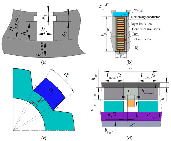 Figure 5. SHM parameters. (a) Stator; (b) Armature winding; (c) Rotor; (d) Axial plane.
bp = wx + ax; hp = 2·(wy + Δw)·Nsec + ay,
The space taken by the slot and layer insulations is taken into account through the constant ax = 1.51 mm, ay = 1.8 mm, Δw = 0.31 mm.
- DC losses in the excitation colis are calculated assuming the net copper fill factor of 0.8. Eddy current losses in the excitation winding are neglected.
- Only the current angles in modes 1,2,3,4 varied during the optimization.
- The following assumption is made to reduce the number of variable parameters during optimization. The current angle in operating point 5 is equal to that in operating point 4. The ratio of currents in the excitation winding section and the armature winding layer is constant among all modes. Additionally, the ratio of the rotor slot widths α2/α1 (see Figure 5c) is constant during the optimization.
Since the principle of operation of SHM is the interaction of the excitation flux and the current of the armature winding, the width of the air gap does not directly affect the torque as long as both the excitation flux and the armature current vector are fixed. However, too small an air gap increases the leakage flux induced by armature winding and flowing through the rotor teeth, which contributes to the reactive power and saturation of the machine. An increase in the air gap results in an increase in the excitation current required to generate the same excitation flux. Therefore, a too large or small air gap is not optimal. During optimization, the optimal gap width was found.
7. Optimization Results
Figure 6 shows that during optimization, the cost function decreased and became almost constant in the end. Figure 7 and Figure 8 show some optimization targets can increase, and less valuable ones can increase as a compromise to allow the cost function to decrease. Figure 7 shows the change in the electrical losses and current magnitude during the optimization stage. Figure 8 depicts the simultaneous change of the symmetrized and nonsymmetrized torque ripple.
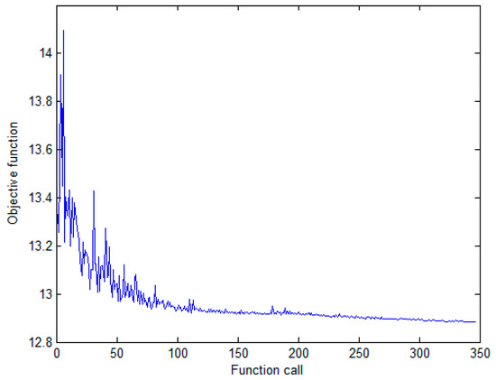
Figure 6.
Variation of the cost function value during optimization.
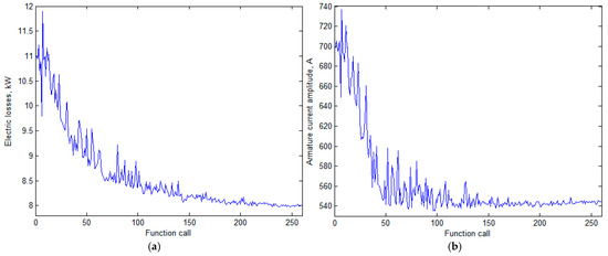
Figure 7.
History of change of the target performances. (a) Average electrical loss; (b) Upper limit of the motor current.
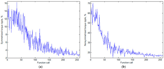
Figure 8.
History of change of the target performances. (a) Symmetrized torque ripple; (b) Nonsymmetrized torque ripple.
A comparison of Figure 9 and Figure 10. shows that as a result of optimization, the permanent magnet area between the teeth has increased significantly, and the rotor teeth have changed shape and become thinner. As the comparison of the flux density plots for points with the maximum torque (Figure 9c–e and Figure 10c–e) shows, after optimization, the area of regions with a flux density value of more than 2 T is significantly reduced. A comparison of Figure 11a,b shows that as a result of the optimization, the maximum demagnetizing force has been reduced from 3 kOe to about 2.5 kOe. So, no check of the demagnetization is needed in this optimization. Table 5 shows the characteristics of the SHM with ferrite magnets before and after optimization.
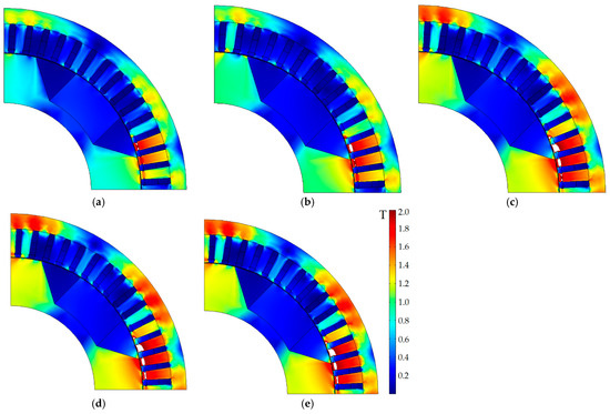
Figure 9.
The cross-section of the initial design of the motor and the plot of flux density magnitude; white areas are the extreme saturation areas (>2 T). (a) Operating point 1; (b) Operating point 2; (c) Operating point 3; (d) Operating point 4; (e) Operating point 5.
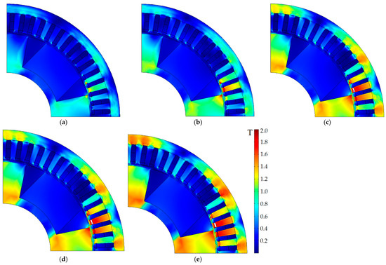
Figure 10.
The cross-section of the optimized design of the motor and the plot of flux density magnitude; white areas are the extreme saturation areas (>2 T). (a) Operating point 1; (b) Operating point 2; (c) Operating point 3; (d) Operating point 4; (e) Operating point 5.
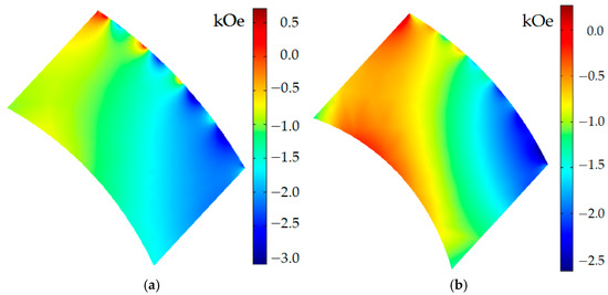
Figure 11.
Demagnetizing force (kOe) in the area of the permanent magnet at operating point 4. (a) Before optimization; (b) After optimization.
Table 5.
Optimization results.
The following conclusions can be made from Table 5 on the optimization results:
- The optimization significantly reduced losses at all operating points, except for operating point 4 at zero speed with maximum torque; it also significantly reduced the average losses and maximum current of the armature winding;
- Average losses according to (1) were reduced by 100% (12.7 − 9.84)/12.7 = 22.5%;
- The maximum current magnitude before optimization was 694 A at operation point 5 at the speed nm, joining the motor modes with the constant power and the constant torque. After optimization, the maximum current magnitude becomes at the operation point 3 at the speed ng, joining the generator modes with the constant power and the constant torque. Thus, the maximum inverter current magnitude was reduced by (694 − 541)/ 694 = 22%;
- In the initial design, the line-to-line voltage limit is reached at operating point 1 in motor mode. In the optimized design, it is reached at operating point 2 in generator mode. Both operating points are at the maximum rotational speed;
- Before optimization, the maximum torque ripple occurs at operating point 2 at maximum speed in generator mode. After optimization, it occurs at operating point 4 at zero speed at maximum torque. Thus, after optimization, the maximum torque ripple was reduced by (11.1 − 2.61)/11.1 = 76.5%, which is because of a significant increase in the airgap;
- Since the exact magnetic properties of the structural non-laminated steel are unknown, the drop in MMF in the non-laminated parts of the magnetic circuit can only be estimated approximately. For the error of such an estimate not to strongly affect the results of the evaluation of the characteristics of the machine, the flux density in these parts made of structural steel must be small. It can be seen that for the initial design, the maximum flux density is 1.2 T, which is less significant than the acceptable values of the magnetic flux density in laminated cores of 1.8 T and more, and for the optimized design, this value is further reduced by 100% (1.2 − 1.15)/1.2 = 4.2%. So, no restriction on the magnetic flux density in non-laminated parts was needed in the optimization.
- As shown in Figure 11, in the initial design, during optimization, and in the optimized design, the demagnetizing field does not exceed 3.2 kOe, while the coercive force of the Y30H-2 magnet is about 4 kOe [36]. As a result of optimization, the demagnetizing field even weakened. Thus, there is no risk of demagnetization of ferrite magnets in all operating points, due to the well-chosen parameters of the initial design.
8. Comparison of SHM with Ferrite Magnets and SHM without Magnets
This section discusses the comparison between the SHM with ferrite magnets, which characteristics are presented in this article, and the SHM without magnets, which characteristics were calculated in our previous study [28]. To avoid repetition in this article, in Table 6 we present only the final optimized characteristics of the SHM without magnets. Details of the SHM design without magnets and its optimization can be found in [28]. Table 6 shows a comparison of the performances of the optimized SHM designs with ferrite magnets and without magnets. The dimensions, masses, and costs of active materials for the SHMs with and without ferrite magnets are compared in Table 7.
Table 6.
Comparison of SHM with ferrite magnets and SHM without magnets.
Table 7.
Comparison of masses, costs, and dimensions of parts of the SHM without magnets and with ferrite magnets.
Comparing the characteristics of the SHMs without permanent magnets and with ferrite magnets, shown in Table 6 and Table 7, the following findings can be reported:
- Average losses according to (1) for the SHM with ferrite magnets are less than for the SHM without ferrite magnets by 100% (12.02 − 9.84)/12.02 = 18.1%;
- The maximum current for the SHM with ferrite magnets is slightly less than for the SHM without ferrite magnets, by 100% (457 − 451)/457 = 1.3%;
- The maximum output torque ripple of the SHM with ferrite magnets is less than that of the SHM without ferrite magnets by 100% (3.91 − 2.61)/3.91 = 33.2% due to the increased air gap;
- The total length excluding the armature winding end parts, including the width of the field winding, for the SHM with ferrite magnets is less than for the SHM without ferrite magnets, by 100% (302.5 − 260)/302.5 = 14%;
- The weight of the rotor sleeve and housing of the SHM with ferrite magnets is two times less than that of the SHM without magnets. This is so, firstly, because the ferrite magnets contribute to the excitation field, and therefore the field of the excitation winding can be reduced. Secondly, the magnetic fluxes created by the ferrite magnets and the excitation winding have opposite directions in the non-laminated parts (the rotor sleeve and housing). Therefore, the saturation of the non-laminated parts is reduced, and the housing of the SHM with ferrites becomes thinner than the SHM case without magnets.
- The total mass of active materials including the rotor sleeve and the motor housing for the SHM with ferrite magnets is 100% (405.9 − 363.1)/363.1 = 10.5% less than the mass of the SHM without magnets;
- The total cost of the active materials (electrical steel, copper, permanent magnets) and structural steel of the rotor sleeve and motor housing for the SHM with ferrite magnets is 1309.9/762.3 = 1.7 times more than that of the SHM without magnets, primarily due to the addition of the cost of ferrite magnets.
9. Conclusions
The optimization procedure based on the single-objective Nelder–Mead algorithm and its results for a synchronous homopolar motor (SHM) with ferrite magnets with a power of 370 kW for driving subway train, taking into account the subway train moving trajectory, namely acceleration and braking stages is described in the article. For one function call, only 5 operating points are to be computed, which makes computational efforts tolerable for computer-aided optimization.
The cost function is constituted from the following optimization objectives: decreasing the average operational cycle, decreasing the upper limit of armature current, and the reduction of the torque ripple. As a result of optimization, the following characteristics of the traction SHM have been improved. Power loss is reduced by 22.5%. The upper limit current of the solid-state inverter is reduced by 22%. The motor torque ripple is reduced by 76.5%.
Based on the optimization results, the obtained characteristics of the SHM with ferrite magnets are compared with the characteristics of the SHM without permanent magnets, optimized by the same method. The comparison of the characteristics of the SHMs with ferrite magnets and without magnets shows that the SHM with ferrite magnets has significant advantages: power loss is reduced by 18.1%, inverter current is reduced by 1.3%, torque ripple is reduced by 33.2%, the total mass of the active materials, rotor sleeve and motor housing is reduced by 10.5%, the overall machine length is reduced by 14%. The advantage of the SHM without magnets is that the cost is 1.7 times less, since it does not use ferrite magnets.
In future work, the comparison between the SHM with ferrite magnets and other types of electrical machines for subway drives and other applications will be carried out.
Author Contributions
Conceptual approach, V.D. and V.P.; data curation, V.D. and V.K.; software, V.D. and V.P.; calculations and modeling, V.D., V.K. and V.P.; writing—original draft, V.D., V.K. and V.P.; visualization, V.D. and V.K.; review and editing, V.D., V.K. and V.P. All authors have read and agreed to the published version of the manuscript.
Funding
The research funding from the Ministry of Science and Higher Education of the Russian Federation (Ural Federal University Program of Development within the Priority-2030 Program) is gratefully acknowledged.
Institutional Review Board Statement
Not applicable.
Informed Consent Statement
Not applicable.
Data Availability Statement
Data are contained within the article.
Acknowledgments
The authors thank the editors and reviewers for careful reading and constructive comments.
Conflicts of Interest
The authors declare no conflict of interest.
References
- Gundogdu, T.; Zhu, Z.-Q.; Chan, C.C. Comparative Study of Permanent Magnet, Conventional, and Advanced Induction Machines for Traction Applications. World Electr. Veh. J. 2022, 13, 137. [Google Scholar] [CrossRef]
- Dianov, A. Highly Efficient Sensorless Multicontrol Mode Compressor IPMSM Drive with Seamless Transitions. IEEE Trans. Power Electron. 2022, 37, 9129–9137. [Google Scholar] [CrossRef]
- Schulze, R. Reducing Environmental Impacts of the Global Rare Earth Production for Use in Nd-Fe-B Magnets, How Magnetic Technologies Much Can Recycling Contribute? Ph.D. Thesis, Technical University of Darmstadt, Darmstadt, Germany, December 2018. Available online: https://tuprints.ulb.tu-darmstadt.de/8301/7/Diss%20Rita%20Schulze%2015-12-2018.pdf (accessed on 30 November 2022).
- Dong, S.; Li, W.; Chen, H.; Han, R. The status of Chinese permanent magnet industry and R&D activities. AIP Adv. 2017, 7, 1–17. [Google Scholar] [CrossRef]
- Carraro, E.; Bianchi, N.; Zhang, S.; Koch, M. Design and Performance Comparison of Fractional Slot Concentrated Winding Spoke Type Synchronous Motors with Different Slot-Pole Combinations. IEEE Trans. Ind. Appl. 2018, 54, 2276–2284. [Google Scholar] [CrossRef]
- De Lima, W.I.B. Rare Earth Industry; Elsevier: Amsterdam, The Netherlands, 2015. [Google Scholar]
- Dmitrievskii, V.; Prakht, V.; Kazakbaev, V.; Anuchin, A. Comparison of Interior Permanent Magnet and Synchronous Homopolar Motors for a Mining Dump Truck Traction Drive Operated in Wide Constant Power Speed Range. Mathematics 2022, 10, 1581. [Google Scholar] [CrossRef]
- Papini, F.; Osama, M. Electromagnetic Design of an Interior Permanent Magnet Motor for Vehicle Traction. In Proceedings of the 2018 XIII International Conference on Electrical Machines (ICEM), Alexandroupoli, Greece, 3–6 September 2018; pp. 205–211. [Google Scholar] [CrossRef]
- Dianov, A. Optimized Field-Weakening Strategy for Control of PM Synchronous Motors. In Proceedings of the 2022 29th International Workshop on Electric Drives: Advances in Power Electronics for Electric Drives (IWED), Moscow, Russia, 26–29 January 2022; pp. 1–6. [Google Scholar] [CrossRef]
- The First-Ever BMW iX3, PressClub Global, Article. Available online: https://www.press.bmwgroup.com/global/article/detail/T0310696EN/the-first-ever-bmw-ix3?language=enhttps://www.netcarshow.com/bmw/2021-ix3 (accessed on 30 November 2022).
- Feustel, S.; Huebner, B.; Loos, D.; Merwerth, J.; Tremaudant, Y.; Vollmer, K. Rotor for Separately Excited Inner Rotor Synchronous Machine, Inner Rotor Synchronous Machine, Motor Vehicle and Method. U.S. Patent US20210006105A1, 7 January 2021. Available online: https://patents.google.com/patent/US20210006105A1 (accessed on 30 November 2022).
- Raia, M.R.; Ruba, M.; Martis, C.; Husar, C.; Sirbu, G.M. Battery electric vehicle (BEV) powertrain modelling and testing for real-time control prototyping platform integration. In Proceedings of the 2021 23rd European Conference on Power Electronics and Applications (EPE’21 ECCE Europe), Ghent, Belgium, 6–10 September 2021; pp. 1–10. Available online: https://ieeexplore.ieee.org/document/9570616 (accessed on 30 November 2022).
- Chu, W.Q.; Zhu, Z.Q.; Zhang, J.; Ge, X.; Liu, X.; Stone, D.; Foster, M. Comparison of electrically excited and interior permanent magnet machines for hybrid electric vehicle application. In Proceedings of the 2014 17th International Conference on Electrical Machines and Systems (ICEMS), Hangzhou, China, 22–25 October 2014; pp. 401–407. [Google Scholar] [CrossRef]
- Illiano, E. Design of a Highly Efficient Brushless Current Excited Synchronous Motor for Automotive Purposes. Ph.D. Thesis, ETH-Zürich, Zürich, Switzerland, 2014. [Google Scholar] [CrossRef]
- Orlova, S.; Pugachov, V.; Levin, N. Hybrid Excitation of the Axial Inductor Machine. Latv. J. Phys. Tech. Sci. 2012, 49, 35–41. [Google Scholar] [CrossRef]
- Bindu, G.; Basheer, J.; Venugopal, A. Analysis and control of rotor eccentricity in a train-lighting alternator. In Proceedings of the 2017 IEEE International Conference on Power, Control, Signals and Instrumentation Engineering (ICPCSI), Chennai, India, 21–22 September 2017; pp. 2021–2025. [Google Scholar] [CrossRef]
- Bianchini, C.; Immovilli, F.; Bellini, A.; Lorenzani, E.; Concari, C.; Scolari, M. Homopolar generators: An overview. In Proceedings of the 2011 IEEE Energy Conversion Congress and Exposition, Phoenix, AZ, USA, 17–22 September 2011; pp. 1523–1527. [Google Scholar] [CrossRef]
- Lorilla, L.; Keim, T.; Lang, J.; Perreault, D. Topologies for future automotive generators. Part I. Modeling and analytics. In Proceedings of the 2005 IEEE Vehicle Power and Propulsion Conference, Chicago, IL, USA, 7 September 2005; pp. 74–85. [Google Scholar] [CrossRef]
- Dmitrievskii, V.; Prakht, V.; Anuchin, A.; Kazakbaev, V. Traction Synchronous Homopolar Motor: Simplified Computation Technique and Experimental Validation. IEEE Access 2020, 8, 185112–185120. [Google Scholar] [CrossRef]
- Lashkevich, M.; Anuchin, A.; Aliamkin, D.; Briz, F. Control strategy for synchronous homopolar motor in traction applications. In Proceedings of the 43rd Annual Conference of the IEEE Industrial Electronics Society (IECON), Beijing, China, 29 October–1 November 2017; pp. 6607–6611. [Google Scholar] [CrossRef]
- Dmitrievskii, V.; Prakht, V.; Anuchin, A.; Kazakbaev, V. Design Optimization of a Traction Synchronous Homopolar Motor. Mathematics 2021, 9, 1352. [Google Scholar] [CrossRef]
- Prakht, V.; Dmitrievskii, V.; Anuchin, A.; Kazakbaev, V. Inverter Volt-Ampere Capacity Reduction by Optimization of the Traction Synchronous Homopolar Motor. Mathematics 2021, 9, 2859. [Google Scholar] [CrossRef]
- Prakht, V.; Dmitrievskii, V.; Kazakbaev, V.; Anuchin, A. Comparative Study of Electrically Excited Conventional and Homopolar Synchronous Motors for the Traction Drive of a Mining Dump Truck Operating in a Wide Speed Range in Field-Weakening Region. Mathematics 2022, 10, 3364. [Google Scholar] [CrossRef]
- Bekhaled, C.; Hlioui, S.; Vido, L.; Gabsi, M.; Lecrivain, M.; Amara, Y. 3D magnetic equivalent circuit model for homopolar hybrid excitation synchronous machines. In Proceedings of the 2007 International Aegean Conference on Electrical Machines and Power Electronics, Bodrum, Turkey, 10–12 September 2007; pp. 575–580. [Google Scholar] [CrossRef]
- Asfirane, S.; Hlioui, S.; Amara, Y.; Gabsi, M. Study of a Hybrid Excitation Synchronous Machine: Modeling and Experimental Validation. Math. Comput. Appl. 2019, 24, 34. [Google Scholar] [CrossRef]
- Hoang, E.; Lécrivain, M.; Hlioui, S.; Gabsi, M. Hybrid excitation synchronous permanent magnets synchronous machines optimally designed for hybrid and full electrical vehicle. In Proceedings of the 8th International Conference on Power Electronics—ECCE Asia, Seogwipo, Republic of Korea, 30 May–3 June 2011. [Google Scholar]
- Ketner, K.; Dirba, J.; Levins, N.; Orlova, S.; Pugachev, V. Inductor Machine with Axial Excitation. L.V. Patent LV13971B, 20 November 2009. (In Latvian). [Google Scholar]
- Dmitrievskii, V.; Prakht, V.; Kazakbaev, V.; Anuchin, A. Design Optimization of the Magnet-Free Synchronous Homopolar Motor of a Subway Train. Appl. Sci. 2022, 12, 12647. [Google Scholar] [CrossRef]
- Cupertino, F.; Pellegrino, G.; Gerada, C. Design of synchronous reluctance machines with multiobjective optimization algorithms. IEEE Trans. Ind. Appl. 2014, 50, 3617–3627. [Google Scholar] [CrossRef]
- Krasopoulos, C.T.; Beniakar, M.E.; Kladas, A.G. Robust Optimization of High-Speed PM Motor Design. IEEE Trans. Magn. 2017, 53, 1–4. [Google Scholar] [CrossRef]
- Fatemi, A.; Ionel, D.; Popescu, M.; Chong, Y.; Demerdash, N. Design Optimization of a High Torque Density Spoke-Type PM Motor for a Formula E Race Drive Cycle. IEEE Trans. Ind. Appl. 2018, 54, 4343–4354. [Google Scholar] [CrossRef]
- Montonen, J.; Nerg, J.; Gulec, M.; Pyrhönen, J. A New Traction Motor System with Integrated-Gear: A Solution for Off-Road Machinery. IEEE Access 2019, 7, 113740–113750. [Google Scholar] [CrossRef]
- Guo, S.; Zhao, H.; Wang, Y.; Yin, X.; Qi, H.; Li, P.; Lin, Z. A Design Technique of Traction Motor for Efficiency Improvement Based on Multiobjective Optimization. World Electr. Veh. J. 2021, 12, 260. [Google Scholar] [CrossRef]
- Lin, F.; Li, X.; Zhao, Y.; Yang, Z. Control Strategies with Dynamic Threshold Adjustment for Supercapacitor Energy Storage System Considering the Train and Substation Characteristics in Urban Rail Transit. Energies 2016, 9, 257. [Google Scholar] [CrossRef]
- IEC. Specifications for Particular Types of Winding Wires—Part 0-2: General Requirements—Enamelled Rectangular Copper Wire; IEC 60317-0-2:2020; IEC: Geneva, Switzerland, 2020; Available online: https://webstore.iec.ch/publication/63495 (accessed on 30 November 2022).
- Grades of Ferrite. The Original Online Company. Bunting. E-Magnets. Available online: https://e-magnetsuk.com/ferrite-magnets/grades-of-ferrite/ (accessed on 8 January 2022).
- Hard Ferrite Magnets, Product Information, IBSMagnet. 2020. Available online: https://ibsmagnet.com/products/dauermagnete/hartferrit.php (accessed on 8 January 2022).
Disclaimer/Publisher’s Note: The statements, opinions and data contained in all publications are solely those of the individual author(s) and contributor(s) and not of MDPI and/or the editor(s). MDPI and/or the editor(s) disclaim responsibility for any injury to people or property resulting from any ideas, methods, instructions or products referred to in the content. |
© 2023 by the authors. Licensee MDPI, Basel, Switzerland. This article is an open access article distributed under the terms and conditions of the Creative Commons Attribution (CC BY) license (https://creativecommons.org/licenses/by/4.0/).