Article

Kinematics Parameter Calibration of Serial Industrial Robots Based on Partial Pose Measurement

1
College of Civil Aviation, Nanjing University of Aeronautics and Astronautics, Nanjing 210016, China
2
School of Automation, Nanjing Institute of Technology, Nanjing 210096, China
*
Author to whom correspondence should be addressed.
Mathematics 2023, 11(23), 4802; https://doi.org/10.3390/math11234802
Submission received: 27 October 2023 / Revised: 24 November 2023 / Accepted: 26 November 2023 / Published: 28 November 2023

Abstract

:
The kinematics parameter error is the main error factor that affects the absolute accuracy of industrial robots. The absolute accuracy of industrial robots can be effectively improved through kinematics calibration. The error model-based method is one of the main methods for calibrating the kinematics parameter error. This paper presents a kinematics parameter calibration method for serial industrial robots based on partial pose measurement. Firstly, the kinematics and the pose error models have been established based on the modified Denavit–Hartenberg (MDH) model. By introducing the concept of error sensitivity, the average significance index is proposed to quantitatively analyze the effects of the kinematics parameter error on the pose error of a robot. The results show that there is no need to measure the full pose error of the robot. Secondly, a partial pose measurement device and method have been presented. The proposed device can measure the position error and the attitude error on the x-axis or y-axis. Finally, the full pose error model, the NP-type partial pose error model, and the OP-type partial pose error model have been applied for calibrating the kinematics parameter errors. The experimental results show that the effectiveness of the OP-type partial pose error model is consistent with the full pose error model.

1. Introduction

In recent years, robotics technology has developed rapidly, and industrial robots are gradually being used in fields of high-end manufacturing [1], such as intelligent grinding and polishing operations for aerospace engines, drilling and riveting in the aerospace industry, and online measurement systems for manufacturing sites [2,3,4,5]. From 2017 to 2020, the Ministry of Science and Technology of China implemented the “intelligent robot” key research and development plan, which pointed out that when industrial robots were used in a certain type of high-end manufacturing field, the absolute position accuracy should be better than 0.1 mm and the attitude accuracy should be better than 0.1° [6]. The COMET project funded by the European Union from 2010 to 2013 was intended to study the key technologies of industrial robots in mechanical processing, of which the goals were to realize a high-precision, low-cost, and flexible processing system [7]. The COMET project pointed out that the absolute position accuracy of industrial robots must be better than 0.05 mm to meet the accuracy requirements of machining operations. However, the repetitive positioning accuracy of most serial industrial robots can reach within 0.01 mm~0.1 mm, although the absolute positioning accuracy of serial industrial robots is still poor, which cannot meet the application accuracy requirements of high-end manufacturing fields [8].
The relevant research has shown that error compensation technology can effectively improve the absolute positioning accuracy of industrial robots [9]. At present, the error compensation technology of industrial robots is divided into online compensation technology and offline compensation technology. The online compensation technology uses high-precision measurement equipment to obtain the end pose of the robot in real time and directly corrects the pose deviation through an error compensation algorithm. Bonev I. of the University of Quebec and others used a C-Track 780 vision measuring instrument to realize the online compensation of the FANUC 200iC robot pose [10]. The offline compensation technology is also called error calibration, and it is usually divided into the model-based method and the non-model-based method. Based on the position error model method, Bonev I. of the University of Quebec improved the average positioning accuracy of the FANUC 200iC robot from 0.873 mm to 0.479 mm [11]. Professor Liao Wenhe of Nanjing University of Aeronautics and Astronautics and others improved the average positioning accuracy of the KUKA KR-30HA robot by 81.6% based on the spatial interpolation method [12]. The industrial robot after offline compensation does not need external measuring equipment during operation and has strong adaptability and versatility.
The positioning error of industrial robots is usually divided into the joint error, the kinematics parameter calibration error, and the non-kinematics parameter calibration error [13]. The kinematics parameter calibration error is the main factor affecting the absolute positioning accuracy of the robot [14]. Kinematics parameters mainly describe the geometric configuration relation between the neighboring connecting links, and it is generally considered that the kinematics parameter error is fixed. The kinematics parameter calibration is mainly divided into the error model calibration method [15] and the axis measurement calibration method. The axis measurement method is also called the circle point analysis (CPA) method [16]. When the robot is unloaded, the single axis rotates one by one to obtain the axis direction vector and then calculate the kinematics parameters. Based on the CPA method, Santolaria J. et al. of the University of Zaragoza improved the positioning accuracy of the KUKA KR-5 robot from 0.40 mm to 0.11 mm [17]. The calibration process of the error model calibration method includes four steps, i.e., modeling, measurement, identification, and compensation. The most commonly used model is the Denavit–Hartenberg (DH) model proposed by Denavit and Hartenberg [18,19]. However, due to the problems of non-integrity and discontinuity in the DH model, researchers have successively proposed improved models such as the zero reference model [20], product of exponentials (POE) model [21], complete and parametrically continuous (CPC) model [22], and MDH model [23]. Wu L. of Tsinghua University et al. realized the parameter calibration of the ABB IRB120 robot based on the POE model and increased the average positioning error from 18.17 mm to 0.266 mm [24]. Klimchik A. and others of the Central Institute of Technology in Nantes used a laser tracker to increase the positioning accuracy of the KUKA KR-270 robot to 0.17 mm [25]. Professor Gao Guanbin of Kunming University of Science and Technology and others simplified the error model through parameter redundancy analysis, which effectively improved the positioning accuracy of the REBOT-S6 robot in three axial directions [26]. Bonev I. of the University of Quebec used spherical constraints to improve the positioning accuracy of the FANUC 200iC robot from 0.698 mm to 0.086 mm [27].
According to the different measuring equipment or measuring targets used in the robot calibration process, the established error model is mainly divided into the distance error model [28], the position error model [29], and the pose error model [30]. Compared with the position error model and the pose error model, the distance error model does not need to perform the transformation between the measurement coordinate system and the robot base coordinate system. Therefore, the error introduced in the measurement step is smaller. Zhang T. of South China University of Technology and others improved the average positioning accuracy of the GSK08 robot from 2.722 mm to 0.0458 mm based on the distance error model [31]. The position error model and the pose error model are currently more commonly used calibration models. The pose error model comprehensively describes the end position and attitude errors of the robot, which is more comprehensive and complete. However, the measurement of the robot’s end pose requires special equipment.
Bonev I. of the University of Quebec used the C-Track 780 vision measuring instrument to measure the pose error of the FANUC 200iC robot [10]. Wen X. of Nanjing Institute of Technology and others used the dedicated pose measurement device T-MAC equipped with a Leica AT960 laser tracker to realize the error measurement of the Staubli TX60 robot. While the price of T-MAC equipment is relatively high, the weight of the device is relatively heavy. It is not suitable for the calibration of low-load robots [32]. Nguyen H. of the University of Ulsan in South Korea and others designed a device and method that can realize the full pose measurement of the robot’s end pose by rotating a fixed angle with only a target ball, and they used the device to achieve the calibration of the robot’s kinematics parameters [33]. Shi X. of Tianjin University and others used a Faro laser tracker to measure the linear motion of the target ball in the tool coordinate system, realized the measurement of the axis direction vectors of the tool coordinate system, and then calculated the robot pose error [34]. Wu Y. and others of the National Institute of Advanced Engineering in France used three target balls to measure the robot’s end pose error and increased the average positioning error of the KUKA KR-270 robot from 0.54 mm to 0.1 mm [35].
All the relevant research has been listed in Table 1. Taking the above research results as references, this paper mainly studies the robot kinematics calibration method based on the partial pose measurement method. The error model of the robot to be calibrated is established based on the MDH model, and the influence of the robot kinematics parameter error on the robot’s end pose error is analyzed in Section 2. A partial pose measurement device and method based on the results of parameter significance analysis are proposed in Section 3. The device is suitable for the pose measurement of a robot with a small load and the proposed method only needs partial pose data to obtain the robot pose information, which is more efficient and convenient. The industrial robot calibration system is briefly introduced and the calibration effect of kinematics parameters based on the partial pose error model is verified through an experimental comparison in Section 4. A conclusion and future research work are given in Section 5.

2. Analysis of the Pose Error Model and Error Significance

2.1. Establishment of the Pose Error Model Based on the MDH Model

As shown in Figure 1a, the classical DH model uses four parameters, i.e., the link length a, the link distance d, the link torsion angle α, and the joint angle θ, to describe the pose relation between the neighboring links. However, when the two neighboring axes are parallel or nearly parallel, the DH model has the problem of singularity, which is not conducive to the calibration of the kinematics parameters. To solve the above problems, Hayati added an angle parameter β to describe the position relation between neighboring parallel axes, as shown in Figure 1b. This model is called the MDH model [20]. The transformation matrix between the neighboring link coordinate systems of the robot is shown in Equation (1).
A i = R o t ( Z i , θ i ) × T r a n s ( Z i , d i ) × T r a n s ( X i , a i ) × R o t ( X i , α i ) × R o t ( Y i , β i ) = [ s θ i s α i s β i + c θ i c β i s θ i c α i c θ i s α i s β i + s θ i c β i c θ i c α i c α i s β i s α i 0 0 s θ i s α i c β i + c θ i s β i a i c θ i c θ i s α i c β i + s θ i s β i a i s θ i c α i c β i d i 0 0 ]
where ai, di, αi, θi, and βi are the values of the link length, the link distance, the link torsion angle, the joint angle, and the joint torsion angle of the i-th joint, respectively (i = 1, 2, …, 6). Moreover, s and c represent the abbreviations of sin and cos, respectively.
Therefore, the nominal pose of the industrial robot’s end in its base coordinate system can be expressed as Equation (2) [36].
T n = A 1 n A 2 n A 3 n A 4 n A 5 n A 6 n = [ R n P n 0 1 ]
where Rn and Pn are the nominal rotation matrix and the nominal displacement matrix, respectively.
However, due to the processing and assembly of robot components, the robot kinematics parameters will inevitably deviate from the nominal parameters. In this paper, the errors of the robot kinematics model parameters ai, di, αi, θi, and βi are defined as Δai, Δdi, Δαi, Δθi, and Δβi, respectively. The actual end pose of the robot can be calculated using the matrix Tr:
T r = A 1 r A 2 r A 3 r A 4 r A 5 r A 6 r = [ R r P r 0 1 ]
where Rr and Pr are the actual rotation matrix and the actual displacement matrix, and the subscript r indicates that the transformation matrix is substituted into the actual kinematics model parameters.
The industrial robot Staubli TX60 to be calibrated in this paper is shown in Figure 2. The nominal values of its MDH model parameters are shown in Table 2. Since joint 2 and joint 3 are theoretically parallel, the kinematics model parameter d2 is equal to 0 and the parameters βi of all the joints are 0. At this time, Equation (1) is equal to that of the traditional DH model.
The establishment of the error model is one of the key steps in the robot calibration process, which determines the identification accuracy of the robot kinematics parameters. Compared with the position error model and the distance error model, the pose error model can more completely describe the error characteristics of the robot.
The positioning error of the robot’s end is defined as the difference ΔT between the actual pose matrix Tr and the nominal pose matrix Tn.
Δ T = T r T n = [ Δ n Δ o Δ a Δ p 0 0 0 0 ]
where [Δn Δo Δa] is the column vector of the attitude error matrix ΔR, and Δp is the position error vector.
Taking the partial differentiation of TN to the kinematics parameters and ignoring the higher-order terms, the robot kinematics error model can be obtained as Equation (5).
[ Δ p Δ n Δ o Δ a ] = [ p r p n n r n n o r o n a r a n ] = [ H p H n H o H a ] Δ η
where Δ η = [ Δ θ i Δ d i Δ a i Δ α i Δ β i ] is the kinematics parameter error to be identified, and H p , H n , H o , H a are the position Jacobian matrix and the attitude Jacobian matrix.
{ H p = [ p j θ i p j d i p j a i p j α i p j β i ] T H n = [ n j θ i n j d i n j a i n j α i n j β i ] T H o = [ o j θ i o j d i o j a i o j α i o j β i ] T H a = [ a j θ i a j d i a j a i a j α i a j β i ] T
Equation (5) can be rewritten into the matrix form as follows:
Δ E = H Δ η
where Δ E = [ Δ P T Δ n T Δ o T Δ a T ] T is the pose error vector, and H = [ H P T H n T H o T H a T ] T is the Jacobian matrix of the pose error model of the MDH model.

2.2. Significance Analysis of Kinematics Parameters

The robot’s end pose error is combined with the kinematics parameter errors, and each kinematics parameter error has a different effect on the end pose error of the robot. To characterize the influence degree of each parameter error on the end pose error, the kinematics parameter error sensitivity concept is proposed. Its definition is shown as Equation (8).
{ S P i = P q i , S n i = n q i S o i = o q i , S a i = a q i
where qi is the MDH parameter of the robot, SPi is the position error sensitive vector of the MDH parameter of the robot, and [Sni, Soi, Sai] is the attitude error sensitive vector of the MDH parameter.
However, SPi, Sni, Soi, and Sai are all three-dimensional vectors, and it is impossible to quantitatively analyze the effect of the parameters. In order to quantify the effect of the kinematics parameter error on the end pose error, the definition of Equation (9) is introduced to express the projection length of the error vector caused by the kinematics parameter i on the robot’s end error vector. e ¯ p i , e ¯ n i , e ¯ o i , e ¯ a i represent the significance index of each kinematics parameter on the position vector, attitude vector on the x-axis, attitude vector on the y-axis, and attitude vector on the z-axis, respectively.
{ e p i = ( S P i d P ) d q i d P , e n i = ( S n i d n ) d q i d n e o i = ( S oi d o ) d q i d o , e a i = ( S a i d a ) d q i d a
where d q i represents the error value of the kinematics parameter.
The same kinematics parameter error may cause different errors in different poses. N sampling points are randomly selected, and the average significance index of each kinematics parameter is solved separately, which is used to comprehensively characterize the influence degree of the kinematics parameter on the attitude error of the robot’s end. The average significance index is calculated as follows:
{ e ¯ p i = 1 N k = 1 N e p i k , e ¯ n i = 1 N k = 1 N e n i k e ¯ o i = 1 N k = 1 N e o i k , e ¯ a i = 1 N k = 1 N e a i k
According to the above definition, 50 test points are randomly selected in the joint space of the industrial robot. The nominal value of the kinematics parameter qi is added with an error of 0.1. For example, di and ai are added with an error of 0.1 mm respectively, and βi, αi, and θi are added with 0.1 rad error, respectively. The nominal pose Tn without the parameter error and the actual pose Tr with the parameter error of the 50 test points are calculated. The robot’s end pose error is calculated according to Equation (4). The average significance index of the corresponding kinematics parameter is calculated according to Equation (10). The simulation calculation results are shown in Figure 3.
It can be seen from Figure 3a that the kinematics parameter errors α6 and θ6 do not affect the end position error of the robot, while the other parameters will cause the end position error of the robot. The kinematics parameters α0, β0, α1, θ2, α3, and θ3 have a greater impact on the robot’s end position error. It can be seen from Figure 3b–d that the kinematics parameter errors di and ai do not affect the robot’s end pose error. The kinematics parameters α1, θ1, α2, β2, α3, θ4, α6, and θ6 have a greater impact on the robot’s end attitude error. And it can also be seen from the figure that the average significance index e ¯ n i , e ¯ o i , e ¯ a i corresponding to the kinematics parameters is more balanced, indicating that the kinematics parameter error has a more balanced influence on the axial attitude of the robot’s end. Therefore, it is not necessary to realize the measurement of the three axial attitude errors in the actual measurement process. And the measurement of a single-axis attitude error, with the partial pose error model, can also realize the accurate identification of robot kinematics parameters. Based on this principle, a partial pose measurement device is designed in this paper, and then the calibration of the kinematics parameters based on this device is implemented. The effect of the calibration results is compared with the full pose error model.

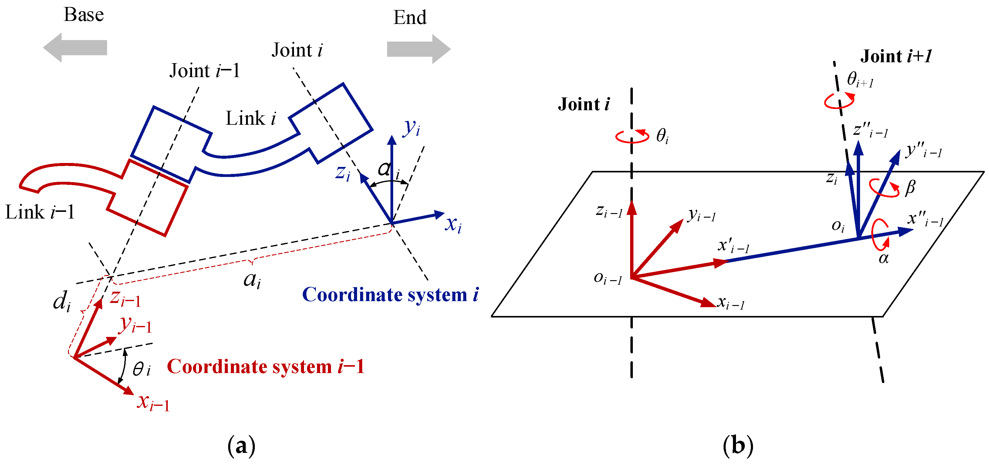
3. The Measurement Method for the Partial Pose

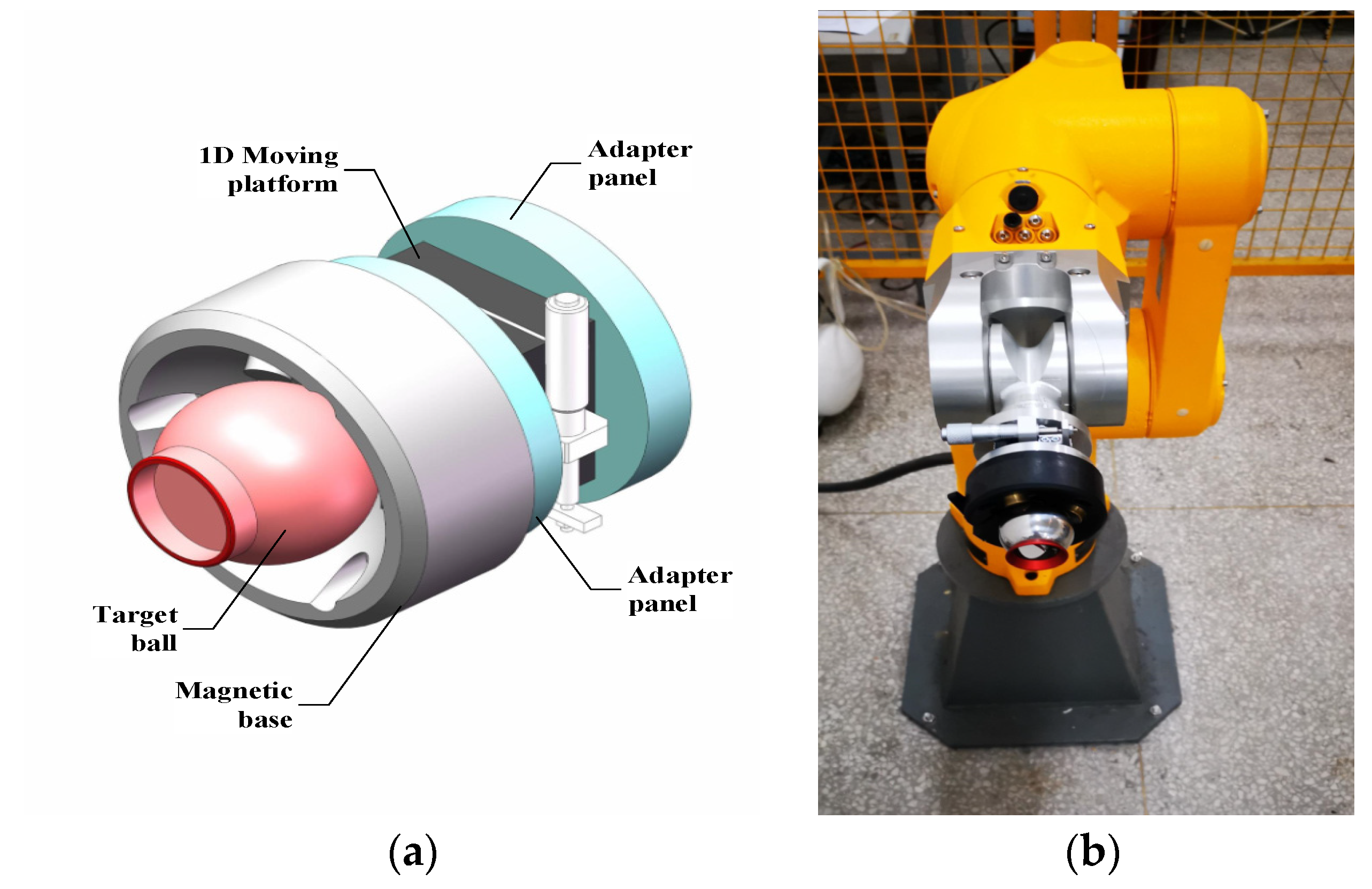
The partial pose measurement device designed in this paper is shown in Figure 4a. The device mainly consists of five parts. The 1.5-inch target ball of the laser tracker is installed in a magnetic base, which is connected with the upper surface of the 1D manual moving platform. The movement of the moving platform is controlled by a manual micrometer. The lower surface of the 1D manual moving platform is fixedly connected with another adapter plate, and the measuring device is fixedly installed on the end flange of the robot, as shown in Figure 4b. The moving direction of the 1D manual moving platform is parallel to the y-axis of the flange, so that the direction vector on the y-axis of the tool coordinate system in the robot’s end can be measured. Similarly, the movement direction of the 1D manual moving platform can be parallel to the x-axis of the flange, so that the direction vector on the x-axis of the tool coordinate system can be measured.
In the actual measurement process for the robot’s end pose, the default position of the 1D manual moving platform is defined as P1 and the point after moving by 10 mm is defined as P2. The point P1 is recorded as the origin point of the coordinate system of the partial pose measuring device. The direction vector formed by the point P2 and the point P1 is recorded as the direction vector on the 
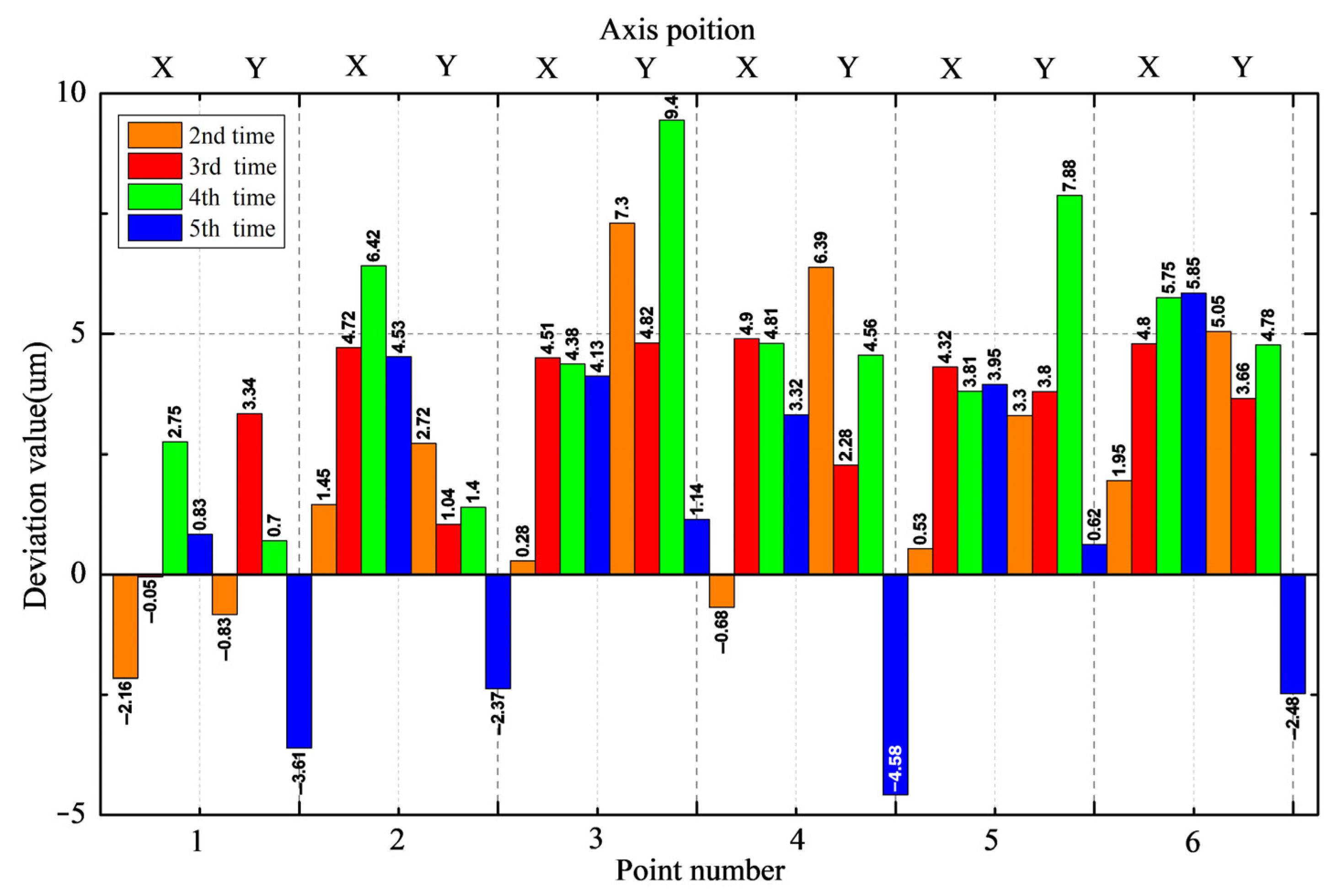
y-axis of the flange coordinate system. According to the performance parameters of the 1D moving platform, the control accuracy is 0.01 mm and the parallelism misalignment is 0.02 mm, which can sufficiently meet the measurement accuracy requirements of the robot’s end. To verify the measurement accuracy of the device, the robot was moved to any position and then the 1D moving platform was manually moved from the point P1 to the point P2, moving 1 mm each time, and the spatial location of the 1.5-inch target ball was recorded by the laser tracker five times. The above steps were repeated 5 times to calculate the repeatability of the operation and the accuracy of the device. The experimental results are shown in Figure 5. The first-time record is set as a reference. And comparing with the other four times, the deviation value can be obtained. There is a fixed position deviation on the x-axis of the device for every 1 mm movement on the y-axis direction. When the device moves by a length of 1 mm, there will be a position error on the x-axis. The error can be treated as a system error to compensate. In addition, the repeatability of the partial pose measurement device is better than 0.005 mm.
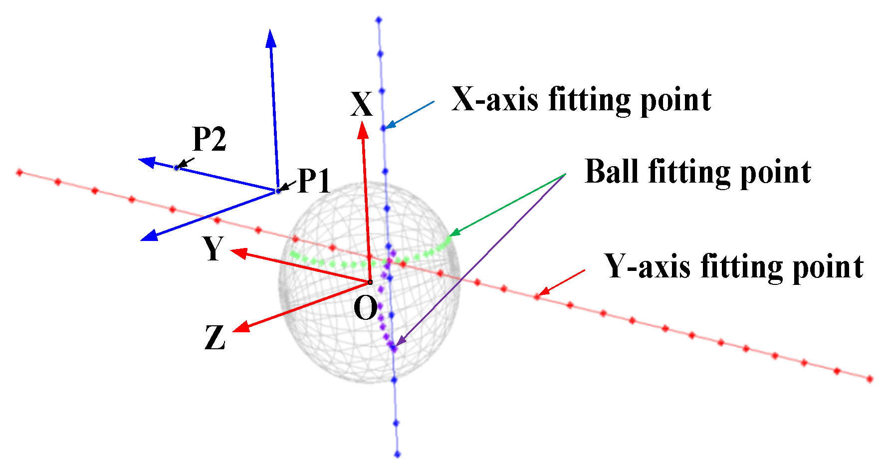
After the error compensation of the partial pose measurement device is completed, the accuracy of the pose data can be guaranteed. To achieve the robot’s calibration, it is necessary to complete the transformation between the coordinate system of the partial pose measurement device and the coordinate system of the robot’s end flange, as shown in Figure 6. The specific measurement steps are as follows:
Firstly, control the robot to move in the positive direction of the x-axis and the y-axis along the default flange tool coordinate system to obtain the direction vector of the tool coordinate system. Then, control the robot to rotate in the positive direction of the x-axis and the y-axis of the default tool coordinate system. And using the least square multiplying method to fit the ball, the center of the ball is the origin of the flange tool coordinate system. Measure the spatial position of the 1.5-inch target ball at the point P1 using the laser tracker and record the point as P01.
Secondly, control the robot to move to the specified point i through the robot’s teach pendant. Measure and record the spatial position of the target ball at the point P1 as Pi1 using the laser tracker. And then manually adjust the 1D moving platform to move 10 mm, using a laser tracker to measure and record the spatial position of the target ball at the point P2 as Pi2. The unit vector formed by the two points is calculated as Equation (11), and the vector is used to replace the vector o in the matrix R.
L i = ( P i 1 P i 2 ) P i 1 P i 2

4. Robot Calibration Experiments Based on the Partial Pose Error Model

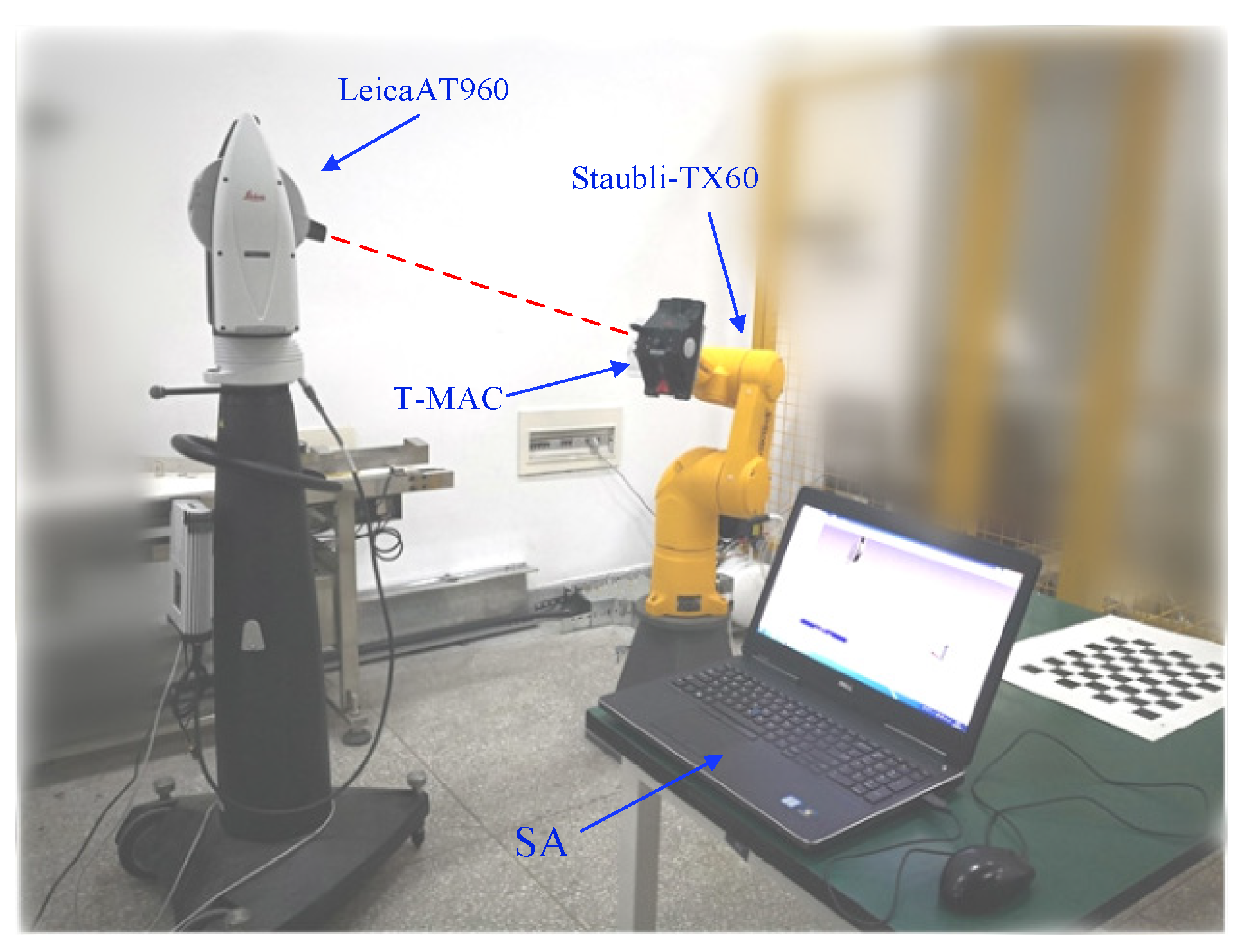
The industrial robot calibration test system built in this paper is shown in Figure 7. A Leica AT960 laser tracker is used in the system, and its measurement uncertainty is ±(15 μm + 6 μm/m). The supporting measurement and analysis software is SpatialAnalyzer2015 (SA), which provides functions including fitting geometry and establishing coordinate systems. The industrial robot to be calibrated with this system is Staubli TX60. The robot has a repeat positioning accuracy of ±0.02 mm, a rated load of 3 kg, and a maximum load of 5 kg. The measurement tools of the laser tracker mainly include a 1.5-inch target ball and a T-MAC measurement tool. The 1.5-inch target ball can only achieve the position measurement, and the T-MAC measurement tool can achieve the pose measurement. The weight of the T-MAC is about 1.5 kg, which is not suitable for the pose measurement of a robot with a small load. A partial pose measurement device designed in this paper. The device is suitable for the pose measurement of a robot with a small load. And the proposed method only needs partial pose data to obtain the robot’s pose information, which is more efficient and convenient. The measurement processes involved in this paper comply with the GB/T 12642-2013 [37] and ISO 9283 [38] industrial robot performance specifications and test method standards.
In this paper, the base coordinate system of the Staubli TX60 robot is used as the reference coordinate system. A total of 300 measurement points are randomly selected in the cube space with a side length of 1000 mm and a center point of (550 mm, 0, 550 mm), and these 300 measurements are distributed as much as possible in the entire cube space. Moreover, 100 measuring points are used to realize the kinematics parameter identification, and the other 200 measuring points are used to realize the identification parameter verification. The robot error measurement based on the full pose error model is achieved by using the T-MAC measurement tool, and the robot error measurement based on the partial pose error model is achieved using the measurement target device designed in this paper. The error model constructed based on the MDH kinematics model is a typical nonlinear equation. The Levenberg–Marquardt (LM) algorithm is a commonly used optimization algorithm for solving the optimal problem of nonlinear equations. The LM algorithm has the advantages of fast and stable convergence and small computational complexity. Thus, the LM algorithm is used for kinematics parameter error identification in this paper.

4.1. Parameter Identification Based on the Full Pose Error Model

The full pose error model contains both the attitude information and the position information. The optimization objective function of the full pose error model is defined as Equation (12).
f = min ( j = 1 N Δ n j 2 + Δ o j 2 + Δ a j 2 + Δ p j 2 )
where j represents the j-th measurement data, and N represents the total number of calibration measurement data. In this paper, the number N is equal to 100.
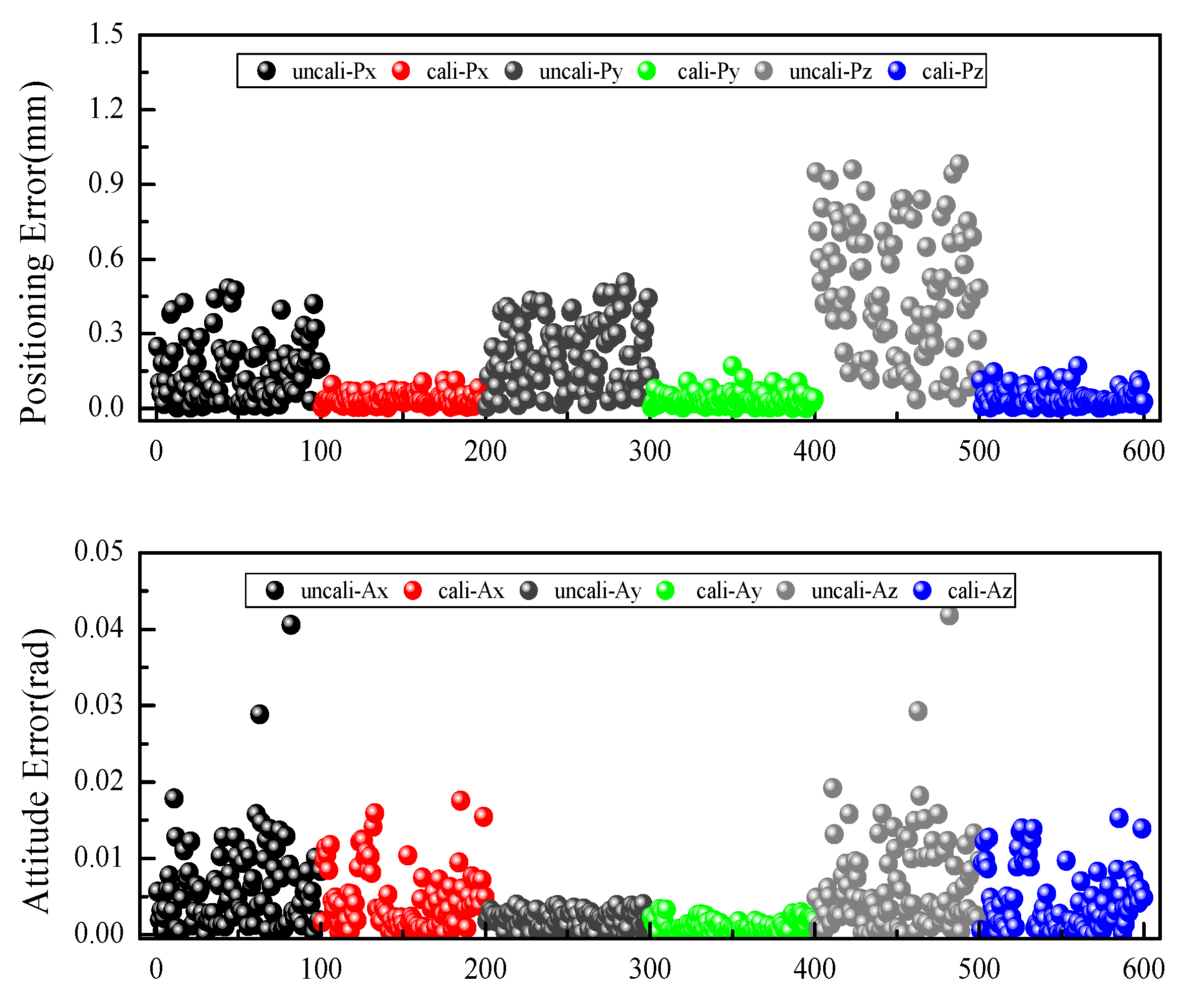
Firstly, the robot’s end error is calculated based on the identification data set. Secondly, the MDH parameter error is identified based on the LM optimization algorithm. The identification results are shown in Table 3. The axial position error and the axial attitude error before and after calibration are shown in Figure 8 and Figure 9. To comprehensively evaluate the calibration effect of the robot, the average comprehensive position error ep and the average comprehensive attitude error eδ are defined as Equation (13).
{ e ¯ p = 1 N i = 1 N Δ p i x 2 + Δ p i y 2 + Δ p i z 2 e ¯ δ = 1 N i = 1 N δ i x 2 + δ i y 2 + δ i z 2
where Δ p i x , Δ p i y , Δ p i z indicate the position error on the x-axis, y-axis, and z-axis, respectively, and δ i x , δ i y , δ i z indicate the attitude error on the x-axis, y-axis, and z-axis, respectively.
As shown in 
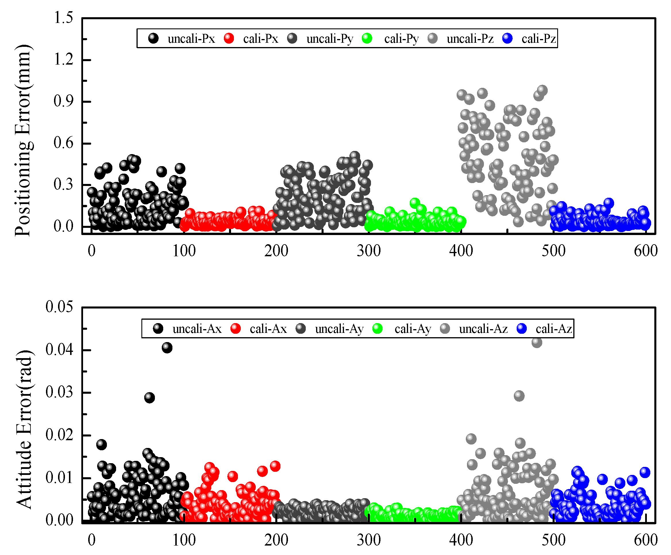
Figure 8, the average position error vector of the robot in the three axes after calibration based on the full pose error model is reduced from (0.151 mm, 0.222 mm, 0.477 mm) to (0.0347 mm, 0.0349 mm, 0.0421 mm). The maximum position error vector is reduced from (0.482 mm, 0.505 mm, 0.980 mm) to (0.110 mm, 0169 mm, 0.167 mm). The average position comprehensive error is reduced from 0.585 mm to 0.0736 mm. The position accuracy of the robot has been greatly improved. The average attitude error vector in the three axes is reduced from (0.00612 rad, 0.002 rad, 0.00638 rad) to (0.00382 rad, 0.00226 rad, 0.00367 rad). The maximum attitude error vector is reduced from (0.0406 rad, 0.00399 rad, 0.0418 rad) to (0.0128 rad, 0.003 rad, 0.0116 rad). The average attitude is reduced from 0.00961 rad to 0.00563 rad. The attitude accuracy of the robot is improved to a small extent.
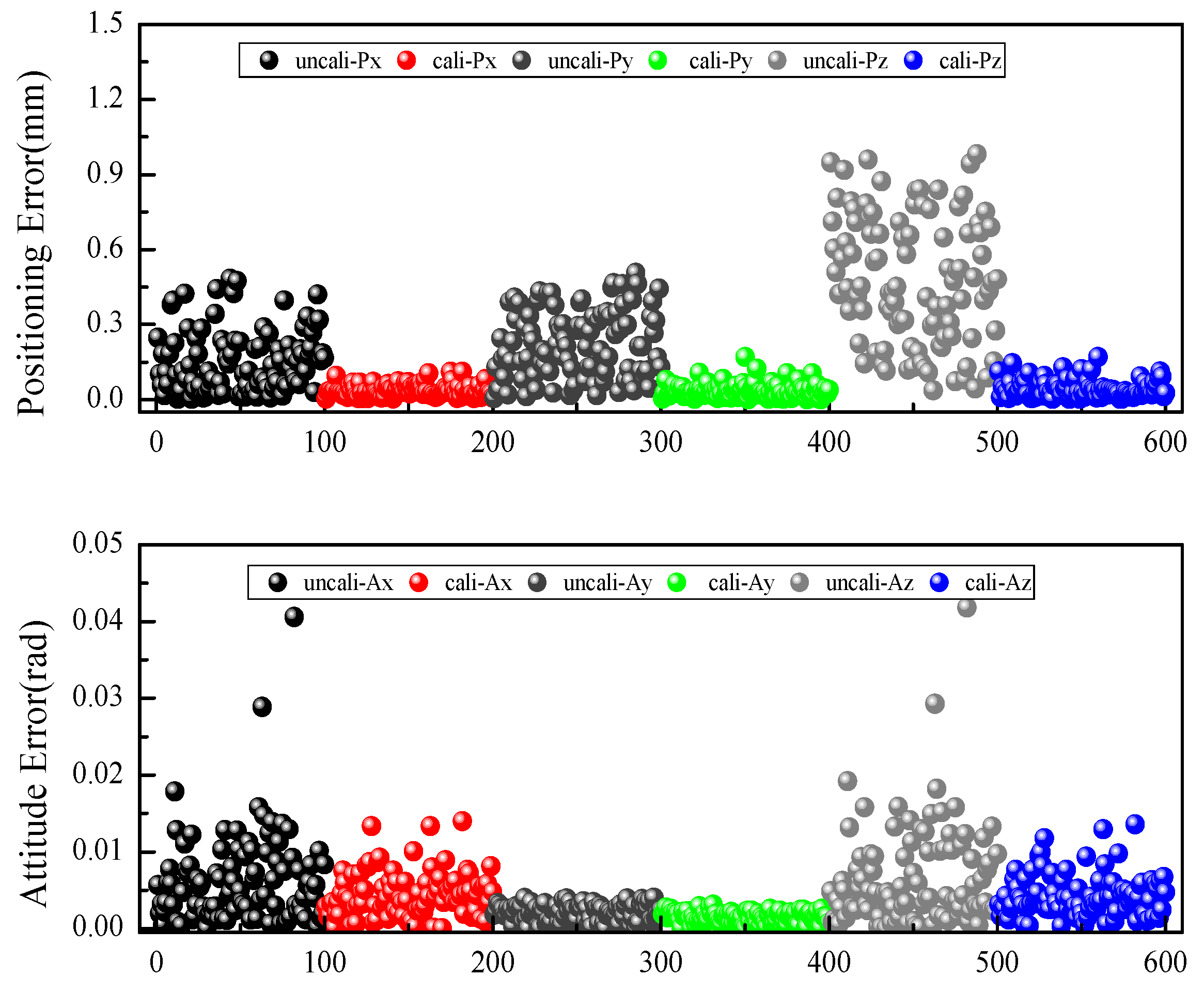
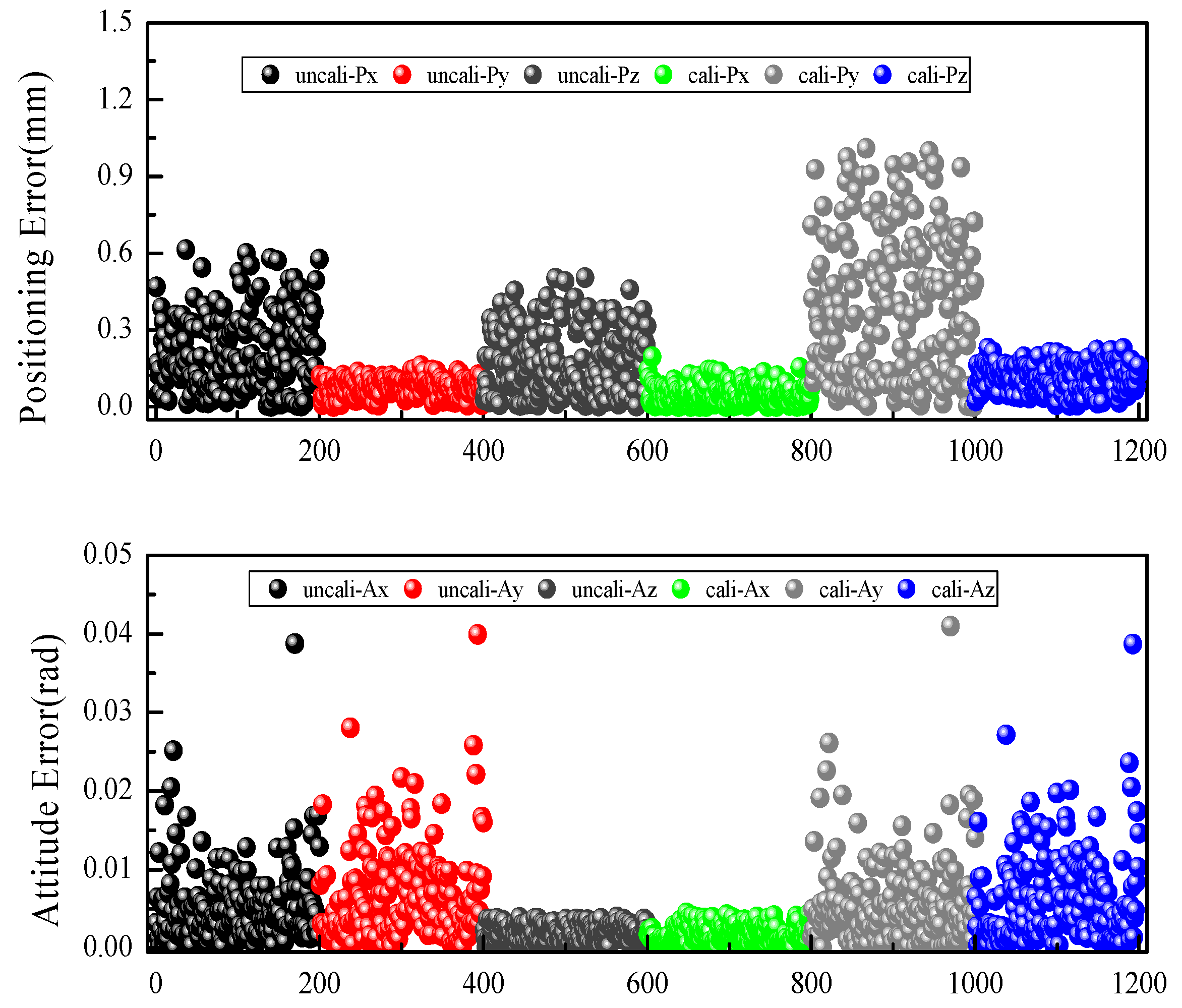
To further verify the calibration effect of the robot, the axial position error and the axial attitude error of the verification data set based on the identified MDH parameters are calculated. The calculation results are shown in Figure 9. The average position error vector of the robot in the three axes is reduced from (0.214 mm, 0.180 mm, 0.399 mm) to (0.0767 mm, 0.0493 mm, 0.113 mm). The maximum position error vector is reduced from (0.613 mm, 0.504 mm, 1.01 mm) to (0.160 mm, 0.196 mm, 0.229 mm). The average comprehensive position error is reduced from 0.547 mm to 0.158 mm, which indicates that the position accuracy of the robot has been greatly improved. The average attitude error vector of the robot in the three axes is reduced from (0.00539 rad, 0.00195 rad, 0.00559 rad) to (0.00479 rad, 0.00156 rad, 0.00455 rad). The maximum attitude error vector is reduced from (0.0388 rad, 0.00393 rad, 0.0410 rad) to (0.0257 rad, 0.00389 rad, 0.0245 rad). The average comprehensive attitude error is reduced from 0.00844 rad to 0.00715 rad, which indicates that the attitude accuracy is improved to a small extent. The error characteristics of the two data sets are basically the same, indicating that the accuracy performance of the robot has been improved.

4.2. Parameter Identification Based on the Partial Pose Error Model

The partial pose measurement device designed in this paper includes two installation states. One of the states is to make the movement direction of the 1D moving platform parallel with the x-axis, and the other is to make the movement direction of the 1D moving platform parallel with the y-axis. Therefore, to prove the effectiveness of the method proposed in this paper, both the data measurements in the two states are obtained.

4.2.1. Parallel with the x-Axis

When the moving direction of the 1D moving platform is parallel with the x-axis, the measured direction vector L is equal to the post data n on the x-axis, and the data used for identification also include position data p. The optimization objective function is shown in Equation (14). In this paper, this model is called the NP-type partial pose error model.
f = min ( j = 1 N Δ n 2 + Δ p 2 )
The MDH parameter errors are identified based on the LM optimization algorithm. The identification results are shown in 
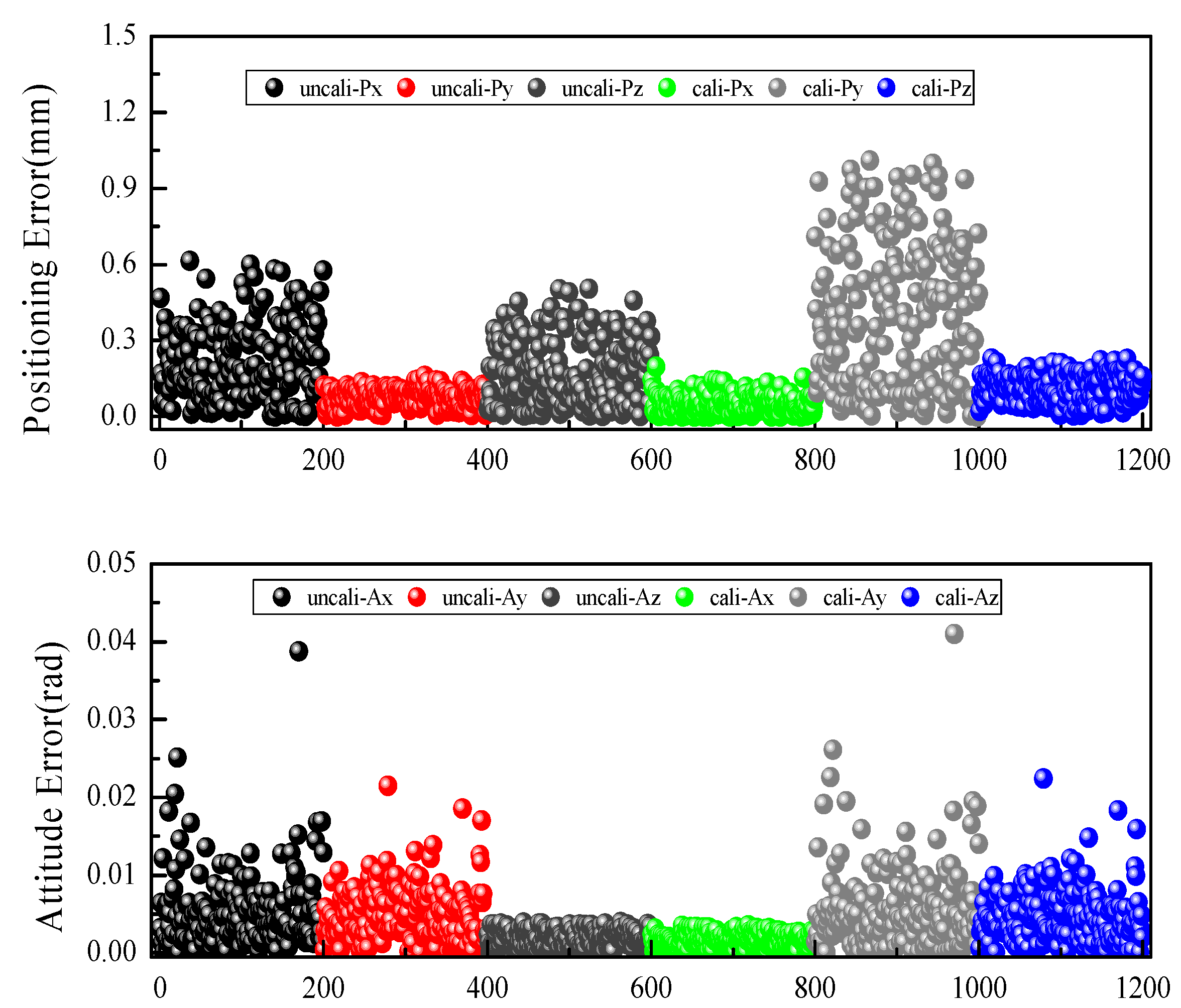
Table 4. Compared with the MDH kinematics parameters identified based on the full pose error model, the difference between the two identified kinematics parameters is relatively small. As shown in Figure 10, the average position error vector of the robot in the three axes after calibration based on the NP-type partial pose error model is reduced from (0.151 mm, 0.222 mm, 0.477 mm) to (0.0347 mm, 0.0349 mm, 0.0421 mm). The maximum position error vector is reduced from (0.482 mm, 0.505 mm, 0.980 mm) to (0.110 mm, 0.169 mm, 0.169 mm). The average comprehensive position error is reduced from 0.585 mm to 0.0736 mm, which shows that the position accuracy of the robot has been greatly improved. This is consistent with the calibration effect of the full pose error model. The average attitude error vector of the robot in the three axes is reduced from (0.00612 rad, 0.002 rad, 0.00638 rad) to (0.00463 rad, 0.00109 rad, 0.00423 rad). The maximum attitude error vector is reduced from (0.0406 rad, 0.00399 rad, 0.0418 rad) to (0.0175 rad, 0.00337 rad, 0.0153 rad). The average comprehensive attitude error is reduced from 0.00961 rad to 0.00656 rad, which shows that the attitude accuracy is improved to a small extent. The calibration effect based on the NP-type partial pose error model is inferior to the effect based on the full pose model.
The verification data set is used to verify the calibration effect of this method, and the identified MDH parameters are used to calculate the axial position error and the axial attitude error of the verification data set. As shown in Figure 11, the average position error vector of the robot in the three axes is reduced from (0.214 mm, 0.180 mm, 0.399 mm) to (0.0768 mm, 0.0493 mm, 0.113 mm). The maximum position error vector is reduced from (0.613 mm, 0.504 mm, 1.01 mm) to (0.160 mm, 0.195 mm, 0.229 mm). The average comprehensive position error is reduced from 0.547 mm to 0.158 mm, which is consistent with the calibration effect of the full attitude error model. The average attitude error of the robot in the three axes is changed from (0.00539 rad, 0.00195 rad, 0.00559 rad) to (0.00664 rad, 0.00181 rad, 0.0061 rad). The maximum attitude error is changed from (0.0388 rad, 0.00393 rad, 0.0410 rad) to (0.0399 rad, 0.00449 rad, 0.0387 rad). The average comprehensive error is changed from 0.00844 rad to 0.00949 rad, which shows that the attitude accuracy of the verification set has not been improved. Therefore, the MDH parameters of the identification set based on the NP-type partial pose error model have poorer generalization ability for the pose optimization than those of the full pose error model.

4.2.2. Parallel with the y-Axis

When the moving direction of the 1D moving platform is parallel with the y-axis, the measured direction vector L is equal to the post data n on the y-axis, and the data used for identification also include position data p. The optimization objective function is shown in Equation (15). In this paper, this model is called the OP-type partial pose error model.
f = min ( j = 1 N Δ o 2 + Δ p 2 )
The MDH parameter errors are identified based on the LM optimization algorithm. The identification results are shown in Table 5. The difference between the MDH kinematics parameters identified based on the full pose error model and the OP-type partial pose error model is relatively small.
As shown in Figure 12, the average position error vector of the robot in the three axes after calibration based on the OP-type partial pose error model is reduced from (0.151 mm, 0.222 mm, 0.477 mm) to (0.0347 mm, 0.0349 mm, 0.0421 mm). The maximum position error vector is reduced from (0.482 mm, 0.505 mm, 0.980 mm) to (0.110 mm, 0.169 mm, 0.169 mm). The average comprehensive position error is reduced from 0.585 mm to 0.0736 mm. The position accuracy of the robot can be improved well based on the OP-type partial pose error model. The average attitude error vector of the robot in the three axes is reduced from (0.00611 rad, 0.002 rad, 0.00638 rad) to (0.00433 rad, 0.00139 rad, 0.00418 rad). The maximum attitude error vector is reduced from (0.0406 rad, 0.00399 rad, 0.0418 rad) to (0.0140 rad, 0.00305 rad, 0.0135 rad). The average comprehensive attitude error is reduced from 0.00961 rad to 0.00643 rad. Compared with the full pose model, the attitude calibration effect is poorer based on the OP-type partial pose error model poor, although it is consistent with the calibration effect based on the NP-type partial error model.
The axial position error and the axial attitude error of the verification data set are calculated based on the identified MDH parameters, and the results are shown in Figure 13. The average position error vector of the robot in the three axes is reduced from (0.214 mm, 0.180 mm, 0.399 mm) to (0.0768 mm, 0.0493 mm, 0.113 mm). The maximum position error vector is reduced from (0.613 mm, 0.504 mm, 1.01 mm) to (0.160 mm, 0.195 mm, 0.229 mm). The average comprehensive position error is reduced from 0.547 mm to 0.158 mm, which is consistent with the calibration results of the other two error models. The average attitude error vector of the robot in the three axes is reduced from (0.00539 rad, 0.00195 rad, 0.00559 rad) to (0.00496 rad, 0.00169 rad, 0.00469 rad). The maximum attitude error vector is reduced from (0.0388 rad, 0.00393 rad, 0.0410 rad) to (0.0215 rad, 0.00355 rad, 0.0224 rad). The average comprehensive attitude error is reduced from 0.00844 rad to 0.00736 rad. The attitude accuracy is improved to a small extent. Therefore, the MDH parameters of the identification set based on the OP-type partial pose error model have slightly poorer generalization ability for the pose than those of the full pose error model, although they are better than those of the NP-type partial attitude error model. It can be seen from 
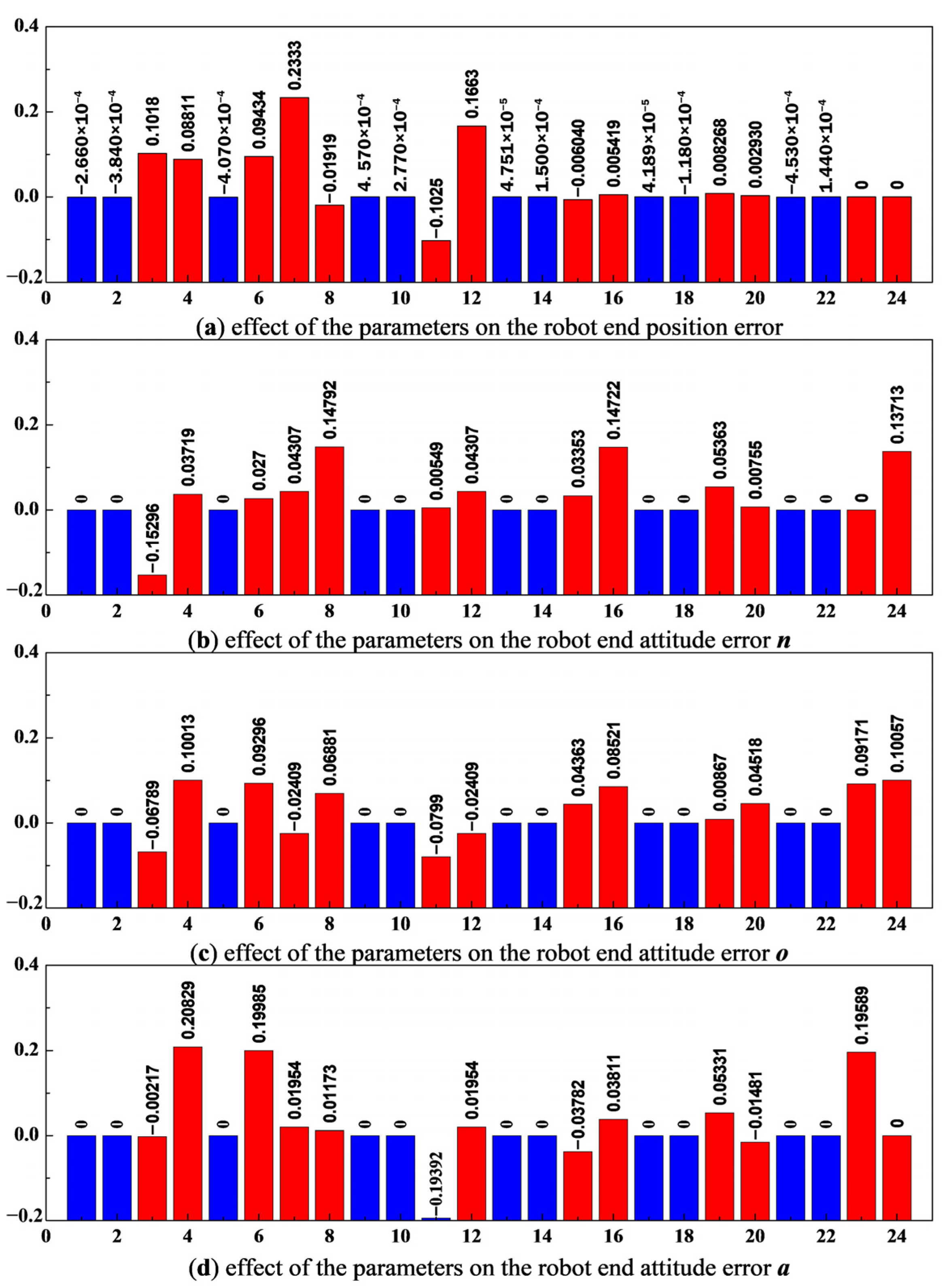
Figure 4 that the average significance indexes e ¯ o i of the MDH kinematics parameters βi, αi, θi are all non-zero, and both the value e ¯ n i of α6 and the value e ¯ a i of θ6 are 0. It can be seen from Table 2, Table 3 and Table 4 that the values of α6 identified based on the OP-type partial pose error model, based on the full pose error model and based on the NP-type partial pose error model are 8.808 × 10⁻⁴, 7.83 × 10⁻⁴, and 1.84 × 10⁻¹⁵, respectively. The value based on the OP-type partial pose error model is quite different from the values identified based on the other two models. Therefore, when using a partial pose device for robot calibration, the OP-type partial pose error model should be used, and the movement direction of the 1D moving platform should be installed parallel to the y-axis of the flange coordinate system of the robot.

5. Conclusions

In this paper, the kinematics model and the pose error model of the Staubli TX60 robot to be calibrated are established based on the MDH model. The average significance index of the kinematics parameters error is proposed, taking the concept of error sensitivity into account. And the influence degree of the kinematics parameters error on the pose error of the robot’s end is quantified and analyzed. According to the influence of the kinematics parameters of the MDH model on the robot attitude error, a partial pose measurement device is proposed. The device can only realize the measurement of the robot position error and the measurement of the direction vector on the x-axis or y-axis. At the same time, the partial pose measurement steps of the device are designed. Finally, based on the built-up industrial robot calibration platform, MDH kinematics parameter identification based on the full pose error model, NP-type partial pose error model and OP-type partial pose error model are realized, respectively. The experimental results show that the position and attitude errors based on the OP-type partial pose error model reduced from (0.585 mm, 0.00961 rad) to (0.0736 mm, 0.00643 rad), which is closer to the calibration effect based on the full pose error model. Meanwhile, the results show that the measurement device designed in this paper is feasible and can effectively reduce the load of the measurement device and the equipment price.

Author Contributions

Conceptualization, T.X.; methodology, H.Z.; software, X.J., G.Q. and C.G.; validation, X.J., G.Q. and C.G.; formal analysis, X.J., G.Q. and C.G.; investigation, T.X.; resources, X.J.; data curation, G.Q.; writing—original draft preparation, T.X.; writing—review and editing, H.Z.; visualization, C.G.; supervision, H.Z.; project administration, G.Q.; funding acquisition, T.X. and G.Q. All authors have read and agreed to the published version of the manuscript.

Funding

This work was supported in part by the Natural Science Foundation of China under Grant 51905258 and by the China Postdoctoral Science Foundation under Grant 2019M650095.

Data Availability Statement

The data presented in this study are available on request from the corresponding author. The data are not publicly available due to our project has not finished yet.

Acknowledgments

The research reported in this paper was carried out at the College of Civil Aviation, Nanjing University of Aeronautics and Astronautics, Nanjing, China, and the School of Automation, Nanjing Institute of Technology, Nanjing, China.

Conflicts of Interest

The authors declare that there are no conflict of interest regarding the publication of this article.

References

  1. Xu, G.; Zhang, Z.; Li, Z.; Guo, X.; Liang, Q.; Liu, X. Multi-objective discrete brainstorming optimizer to solve the stochastic multiple-product robotic disassembly line balancing problem subject to disassembly failures. Mathematics 2023, 11, 1557. [Google Scholar] [CrossRef]
  2. Gan, Y.; Duan, J.; Dai, X. A calibration method of robot kinematic parameters by drawstring displacement sensor. Int. J. Adv. Robot. Syst. 2019, 16, 1729881419883072. [Google Scholar] [CrossRef]
  3. De Rossi, G.; Minelli, M.; Roin, S.; Falezza, F.; Sozzi, A.; Ferraguti, F.; Setti, F.; Bonfè, M.; Secchi, C.; Muradore, R. A first evaluation of a multi-modal learning system to control surgical assistant robots via action segmentation. In IEEE Transactions on Medical Robotics and Bionics; IEEE: Piscataway, NJ, USA, 2021; Volume 3, pp. 714–724. [Google Scholar]
  4. Luo, G.; Zou, L.; Wang, Z.; Lv, C.; Ou, J.; Huang, Y. A novel kinematic parameters calibration method for industrial robot based on Levenberg-Marquardt and Differential Evolution hybrid algorithm. Robot. Comput.-Integr. Manuf. 2021, 71, 102165. [Google Scholar] [CrossRef]
  5. Li, Z.; Li, S.; Luo, X. An overview of calibration technology of industrial robots. IEEE/CAA J. Autom. Sin. 2021, 8, 23–36. [Google Scholar] [CrossRef]
  6. Qiao, G.; Tian, L.; Zhang, Y.; Liu, D.; Song, G. Error Sensitivity Based Redundancy Analysis for Kinematic Calibration of Industrial Robot. In International Conference on Artificial Intelligence and Security; Springer International Publishing: Cham, Switzerland, 2022. [Google Scholar]
  7. Zhu, Z.; Tang, X.; Chen, C.; Peng, F.; Yan, R.; Zhou, L.; Li, Z.; Wu, J. High precision and efficiency robotic milling of complex parts: Challenges, approaches and trends. Chin. J. Aeronaut. 2022, 35, 22–46. [Google Scholar] [CrossRef]
  8. Wang, R.; Guo, X.; Li, S.; Wang, L. Separation and Calibration Method of Structural Parameters of 6R Tandem Robotic Arm Based on Binocular Vision. Mathematics 2023, 11, 2491. [Google Scholar] [CrossRef]
  9. Bo, L.I.; Tian, W.; Zhang, C.; Hua, F.; Gui, F.; Li, Y. Positioning error compensation of an industrial robot using neural networks and experimental study. Chin. J. Aeronaut. 2022, 35, 346–360. [Google Scholar]
  10. Gharaaty, S.; Shu, T.; Joubair, A.; Xie, W.F.; Bonev, I.A. Online pose correction of an industrial robot using an optical coordinate measure machine system. Int. J. Adv. Robot. Syst. 2018, 15, 1729881418787915. [Google Scholar] [CrossRef]
  11. Nubiola, A.; Bonev, I. Absolute robot calibration with a single telescoping ballbar. Precis. Eng. 2014, 38, 472–480. [Google Scholar] [CrossRef]
  12. Zhou, W.; Liao, W.; Tian, W. Theory and experiment of industrial robot accuracy compensation method based on spatial interpolation. Jixie Gongcheng Xuebao (Chin. J. Mech. Eng.) 2013, 49, 42–48. [Google Scholar] [CrossRef]
  13. Ke, X.; Yu, Y.; Li, K.; Wang, T.; Zhong, B.; Wang, Z.; Kong, L.; Guo, J.; Huang, L.; Idir, M.; et al. Review on robot-assisted polishing: Status and future trends. Robot. Comput.-Integr. Manuf. 2023, 80, 102482. [Google Scholar] [CrossRef]
  14. Huang, P.; Huang, H.; Li, Y.; Li, H. Positioning accuracy reliability analysis of industrial robots based on differential kinematics and saddlepoint approximation. Mech. Mach. Theory 2021, 162, 104367. [Google Scholar] [CrossRef]
  15. Bai, M.; Zhang, M.; Zhang, H.; Li, M.; Zhao, J.; Chen, Z. Calibration method based on models and least-squares support vector regression enhancing robot position accuracy. IEEE Access 2021, 9, 136060–136070. [Google Scholar] [CrossRef]
  16. Lattanzi, L.; Cristalli, C.; Massa, D.; Boria, S.; Lépine, P.; Pellicciari, M. Geometrical calibration of a 6-axis robotic arm for high accuracy manufacturing task. Int. J. Adv. Manuf. Technol. 2020, 111, 1813–1829. [Google Scholar] [CrossRef]
  17. Santolaria, J.; Conte, J.; Pueo, M.; Javierre, C. Rotation error modeling and identification for robot kinematic calibration by circle point method. Metrol. Meas. Syst. 2014, 21, 85–98. [Google Scholar] [CrossRef]
  18. Denavit, J.; Hartenberg, R.S. A kinematic notation for lower-pair mechanisms based on matrices. J. Appl. Mech. 1955, 22, 215–221. [Google Scholar] [CrossRef]
  19. Cristoiu, C.; Ivan, M.; Ghionea, I.G.; Pupăză, C. The Importance of Embedding a General forward Kinematic Model for Industrial Robots with Serial Architecture in Order to Compensate for Positioning Errors. Mathematics 2023, 11, 2306. [Google Scholar] [CrossRef]
  20. Mooring, B.W.; Tang, G.R. An improved method for identifying the kinematic parameters in a six axis robot. In International Computers in Engineering Conference and Exhibit; Texas A & M University: College Station, TX, USA, 1984; pp. 79–84. [Google Scholar]
  21. Yang, X.; Wu, L.; Li, J.; Chen, K. A minimal kinematic model for serial robot calibration using POE formula. Robot. Comput.-Integr. Manuf. 2014, 30, 326–334. [Google Scholar] [CrossRef]
  22. Zhuang, H.; Roth, Z.S. Robot calibration using the CPC error model. Robot. Comput.-Integr. Manuf. 1992, 9, 227–237. [Google Scholar] [CrossRef]
  23. Wu, B.; Liu, X.; Zhu, C.; Xu, K. Design and Implementation of a Self-Calibration Method for a Dual-Arm Haptic Device. In Proceedings of the 2022 IEEE International Conference on Robotics and Biomimetics (ROBIO), Jinghong, China, 5–9 December 2022; pp. 409–414. [Google Scholar]
  24. Wu, L.; Yang, X.; Chen, K.; Ren, H. A minimal POE-based model for robotic kinematic calibration with only position measurements. IEEE Trans. Autom. Sci. Eng. 2014, 12, 758–763. [Google Scholar] [CrossRef]
  25. Judd, R.; Knasinski, A. A technique to calibrate industrial robots with experimental verification. In IEEE International Conference on Robotics and Automation; IEEE: Piscataway, NJ, USA, 1987; pp. 351–357. [Google Scholar]
  26. Gao, G.; Sun, G.; Na, J.; Guo, Y.; Wu, X. Structural parameter identification for 6 DOF industrial robots. Mech. Syst. Signal Process. 2018, 113, 145–155. [Google Scholar] [CrossRef]
  27. Joubair, A.; Bonev, I. Kinematic calibration of a six-axis serial robot using distance and sphere constraints. Int. J. Adv. Manuf. Technol. 2015, 77, 515–523. [Google Scholar] [CrossRef]
  28. Mu, N.; Wang, K.; Xie, Z.; Ren, P. Calibration of a flexible measurement system based on industrial articulated robot and structured light sensor. Opt. Eng. 2017, 56, 054103. [Google Scholar] [CrossRef]
  29. Zeng, Y.; Tian, W.; Liao, W. Positional error similarity analysis for error compensation of industrial robots. Robot. Comput.-Integr. Manuf. 2016, 42, 113–120. [Google Scholar] [CrossRef]
  30. Wang, S.; Jia, Q.; Chen, G.; Liu, D. Complete relative pose error model for robot calibration. Ind. Robot. Int. J. Robot. Res. Appl. 2019, 46, 622–630. [Google Scholar] [CrossRef]
  31. Zhang, T.; Du, L.; Dai, X. Test of robot distance error and compensation of kinematic full parameters. Adv. Mech. Eng. 2014, 6, 810684. [Google Scholar] [CrossRef]
  32. Wen, X.; He, S.; Qiao, G.; Wang, D.; Song, A.; Kang, C.; Lv, Z. Uncertainty estimation of robot geometric parameters and end-effecter position based on new generation gps. Math. Probl. Eng. 2019, 2019, 7830489. [Google Scholar] [CrossRef]
  33. Nguyen, H.-N.; Zhou, J.; Kang, H.-J. A new full pose measurement method for robot calibration. Sensors 2013, 13, 9132–9147. [Google Scholar] [CrossRef]
  34. Shi, X.; Zhang, F.; Qu, X.; Liu, B. An online real-time path compensation system for industrial robots based on laser tracker. Int. J. Adv. Robot. Syst. 2016, 13, 1729881416663366. [Google Scholar] [CrossRef]
  35. Wu, Y.; Klimchik, A.; Caro, S.; Furet, B.; Pashkevich, A. Geometric calibration of industrial robots using enhanced partial pose measurements and design of experiments. Robot. Comput.-Integr. Manuf. 2015, 35, 151–168. [Google Scholar] [CrossRef]
  36. Zaplana, I.; Hadfield, H.; Lasenby, J. Singularities of serial robots: Identification and distance computation using geometric algebra. Mathematics 2022, 10, 2068. [Google Scholar] [CrossRef]
  37. GB/T 12642-2013; Performance Specification and Test Method Standard for Industrial Robots. Chinese Standard: Beijing, China, 2013.
  38. ISO 9283; Manipulating Industrial Robots Performance Criteria and Test Methods. ISO: Geneva, Switzerland, 1998.
Figure 1. Schematic diagram of the coordinate system transformation of the MDH model. (a) Modeling of non-parallel joints. (b) Modeling of parallel joints.
Mathematics 11 04802 g001
Figure 2. Schematic diagram of the definition of the coordinate systems of the Staubli TX60 robot.
Mathematics 11 04802 g002
Figure 3. The significance analysis of the parameters of the MDH model. The order of the MDH parameters is a1, d1, α1, θ1, a2, α2, θ2, β2, a3, d3, α3, θ3, a4, d4, α4, θ4, a5, d5, α5, θ5, a6, d6, α6, θ6.
Mathematics 11 04802 g003
Figure 4. The 3D structure diagram (a) and actual installation diagram (b) of the partial pose measurement device designed.
Mathematics 11 04802 g004
Figure 5. Accuracy test results of the partial pose measurement device.
Mathematics 11 04802 g005
Figure 6. Schematic diagram of the calibration method for the flange tool coordinate system.
Mathematics 11 04802 g006
Figure 7. The calibration system for the industrial robot built in this paper.
Mathematics 11 04802 g007
Figure 8. Comparison of the axial position error and the axial attitude error before and after calibration based on the identification data set of the full pose error model.
Mathematics 11 04802 g008
Figure 9. Comparison of the axial position error and the axial attitude error before and after calibration based on the verification data set based on the full pose error model.
Mathematics 11 04802 g009
Figure 10. Comparison of the axial position error and the axial attitude error before and after calibration of the identification data set based on the NP-type partial pose error model.
Mathematics 11 04802 g010
Figure 11. Comparison of the axial position error and the axial attitude error before and after calibration of the verification data set based on the NP-type partial pose error model.
Mathematics 11 04802 g011
Figure 12. Comparison of the axial position error and the axial attitude error before and after calibration based on the identification data set of the OP-type partial pose error model.
Mathematics 11 04802 g012
Figure 13. Comparison of the axial position error and the axial attitude error before and after calibration based on the verification data set of the OP-type partial pose error model.
Mathematics 11 04802 g013
Table 1. The research on the accuracy improvement of industrial robots.
MethodsAverage Positioning Error ImprovementsRobotsResearchers
Position error model methodFrom 0.873 mm to 0.479 mmFANUC 200iCBonev I. of University of Quebec [11]
Spatial interpolation method81.6%KUKA KR-30HALiao W. of Nanjing University of Aeronautics and Astronautics [12]
CPA methodFrom 0.40 mm to 0.11 mmKUKA KR-5Santolaria J. of University of Zaragoza [17]
POE modelFrom 18.17 mm to 0.266 mmABB IRB120Wu L. of Tsinghua University [24]
Using a laser trackerTo 0.17 mmKUKA KR-270Klimchik A. of Central Institute of Technology in Nantes [25]
Spherical constraintsFrom 0.698 mm to 0.086 mmFANUC 200iCBonev I. of University of Quebec [27]
Distance error modelFrom 2.722 mm to 0.0458 mmGSK08Zhang T. of South China University of Technology [31]
Three target balls measurementFrom 0.54 mm to 0.1 mmKUKA KR-270Wu Y. of National Institute of Advanced Engineering in France [35]
Table 2. Nominal parameters of the robot based on the MDH model.
iθi/raddi/mmai/mmαi/radβi/rad
1π00π/20
2π/2029000
3π/2200π/20
4π3100π/20
5π00π/20
6070000
Table 3. The errors of the kinematics parameters identified based on the full pose error model.
iΔθi/radΔdi/mmΔai/mmΔαi/radΔβi/rad
1−0.00015−0.19537−0.244647.36 × 10−50
20.00079700.299495−3.42 × 10−51.79 × 10−5
30.0003430.2025380.0078220.0008770
40.0015110.200548−0.08927−0.000420
50.001−0.06341−0.01266−0.000460
60.001394−0.10686−0.094320.0007830
Table 4. The errors of the kinematics parameters identified based on the NP-type partial pose error model.
iΔθi/radΔdi/mmΔai/mmΔαi/radΔβi/rad
1−1.5 × 10⁻⁴−0.1958−0.24457.37 × 10−50
27.97 × 10−400.2995−3.42 × 10−51.78 × 10−5
33.34 × 10−40.20280.010508.78 × 10−40
41.511 × 10−30.2006−0.08926−0.000420
51.112 × 10⁻³−0.1347−0.02051−0.001470
61.394 × 10⁻³−0.1069−0.094421.84 × 10−150
Table 5. The errors of the kinematics parameters identified based on the OP-type partial pose error model.
iΔθi/radΔdi/mmΔai/mmΔαi/radΔβi/rad
1−1.5 × 10⁻⁴−0.1961−0.24447.37 × 10−50
27.966 × 10−400.2995−3.41 × 10−51.78 × 10−5
33.291 × 10−40.20300.012138.785 × 10−40
41.511 × 10−30.2006−0.08926−4.246 × 10−40
56.888 × 10⁻⁴−4.376 × 10−30.0091343.87 × 10−40
61.394 × 10⁻³−0.1069−0.094498.808 × 10−40
Disclaimer/Publisher’s Note: The statements, opinions and data contained in all publications are solely those of the individual author(s) and contributor(s) and not of MDPI and/or the editor(s). MDPI and/or the editor(s) disclaim responsibility for any injury to people or property resulting from any ideas, methods, instructions or products referred to in the content.

