Abstract
This research continues the previous work “Robotic-Arm-Based Force Control in Neurosurgical Practice”. In that study, authors acquired an optimal control arm speed shape for neurological surgery which minimized a cost function that uses an adaptive scheme to determine the brain tissue force. At the end, the authors proposed the use of reinforcement learning, more specifically Deep Deterministic Policy Gradient (DDPG), to create an agent that could obtain the optimal solution through self-training. In this article, that proposal is carried out by creating an environment, agent (actor and critic), and reward function, that obtain a solution for our problem. However, we have drawn conclusions for potential future enhancements. Additionally, we analyzed the results and identified mistakes that can be improved upon in the future, such as exploring the use of varying desired distances of retraction to enhance training.
Keywords:
neurosurgical robotics; optimal control; reinforcement learning; deep deterministic policy gradient MSC:
68T40; 68U10; 68T01; 68T05
1. Introduction
This article is the continuation of the work developed in [1]. As stated in that work, studies indicate that every year, 22.6 million people suffer neurological injuries and 13.8 million of them must go to the operating room [2]. Only in the USA and according to the American Society of Neurological Surgeons (AANS), 50,000 neuro surgeries lasting more than half an hour are performed each year and studies indicate that brain tissue begins to undergo tension about a quarter of an hour after the beginning of the operation [3].
In order to prevent ischemia discomfort, medical professionals emphasize the crucial need for maintaining an appropriate volume of the inner brain artery, with a recommended level higher than 10–13 mL per 100 gm−1 min1. Additionally, Bell et al. [4] and the research of Laha et al. [5] indicate that brain injury can occur when mean arterial pressure is off by less than 70 mmHg from the brain’s retraction pressure, but that full recovery can occur when the deviation is beyond 200 mmHg. Notably, the frequency of postoperative problems varies depending on the complexity of the surgical treatment, with an incidence between 3% and 9% [6,7]. Brain retraction in skull base surgery causes particular complications in about 10% of surgeries, which might result in problems such parenchymal hematomas, aphasia, hemiparesis, and numbness, see the work of Laha et al. [5].
Intriguingly, the human brain is an incredibly complex organ, and its response to surgical procedures involves a delicate interplay of various factors. The impact of brain retraction extends beyond immediate mechanical stress; it can also influence cerebral blood flow and intracranial pressure. When the brain is retracted, it can compress blood vessels, potentially compromising blood flow to vital regions. This reduced blood supply can lead to ischemia, which can have severe consequences, including neuronal damage and cognitive deficits [8]. Therefore, the meticulous management of brain retraction is crucial not only for preventing immediate tissue damage but also for safeguarding the brain’s overall functionality.
Moreover, it is worth noting that the brain’s sensitivity to pressure variations can vary significantly from person to person. Factors such as age, overall health, and pre-existing conditions can influence how the brain responds to retraction. Older individuals or those with vascular disorders may be more vulnerable to complications related to brain retraction, emphasizing the need for personalized approaches in neurosurgical procedures [9].
Medical practitioners have taken a number of steps to improve surgical outcomes in light of these alarming figures. Two significant developments are the adoption of minimally invasive surgery (MIS) techniques as an alternative to traditional operations, which minimizes the requirement for large incisions, and the introduction of surgical robots [3] to overcome human limits and improve surgical precision. Combining these developments has created minimally invasive robotic surgery (MIRS), in which robots work with surgeons to extend surgical options and bypass human limits. Patients who receive MIRS experience a quicker return to baseline function, less postoperative discomfort, shorter hospital stays, less immune system stress, and cheaper healthcare expenses [10,11,12]. Hoecklemann has defined three primary categories for MIRS: teleoperated systems, where robots collaborate with medical professionals via an interface; image-guided systems, where robots carry out predetermined surgical plans using intraoperative geometric data obtained from navigation or tracking systems; and active guidance, where medical professionals have manual control over the robotic system [13,14].
This article primarily focuses on the critical aspect of brain retraction during surgical procedures (refer to Figure 1). In surgeries involving access to areas deep within the brain, surgeons employ a technique called “brain retraction” [15]. This maneuver involves carefully separating the natural folds of the brain to access the targeted area within. However, experts caution that the pressure applied during brain retraction can potentially damage brain tissue, and the extent of damage depends on several factors, including the magnitude and duration of the pressure, gravitational effects, fluid loss, the brain’s rigidity, and the limit of deformation (typically around 20 mm) [3,10,11,12,16,17]. High pressure during retraction can lead to brain contusions and infarctions, compromising oxygen supply due to vein deformations and swelling.
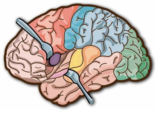
Figure 1.
Brain retraction.
In a groundbreaking study outlined in a prior work [1], researchers introduced the use of a robotic system to assist with brain retraction (Table 1). They formulated a control law equation, derived from variational calculus, which provided an optimal speed for the robotic brain retractor, denoted as Equation (1). This equation incorporates three lambda coefficients to model the robotic arm’s behavior, and the precise definition of these coefficients is crucial for achieving the correct speed profile.

Table 1.
Control parameters and variables from [1].
The robotic brain retractor must reach the desired final position, have a final speed of zero, and start at a position of zero. The ideal speed is determined by Equation (1) and accomplishes these three critical goals.
The point of interaction, the preceding position, and the applied force are all inputs into this control system (Figure 2), which only has one output—speed.
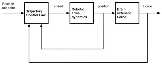
Figure 2.
Control structure used in [1] based on variational calculus.
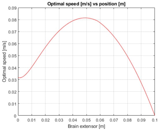
Figure 3.
Robotic arm speed vs. position.
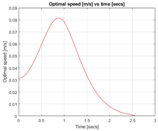
Figure 4.
Robotic arm speed over time.
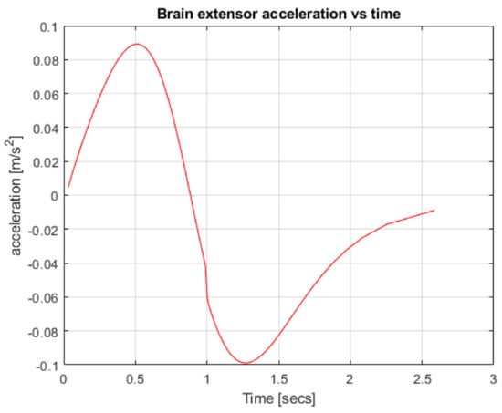
Figure 5.
Robotic arm acceleration over time.
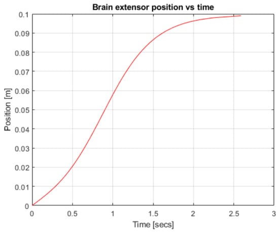
Figure 6.
Robotic arm position over time.
In [1], when discussing future improvements, it was proposed to use deep reinforcement learning techniques for the configuration of the controller; such techniques could then be applied to the research to improve and adapt the control law. Considering everything stated above, we will now go over how to apply these methods to the application we just mentioned. It is important to note that this is a highly analytical result, and one can only support it if they have a very accurate and linear model of brain tissue.
Furthermore, in the existing literature, several research works, such as the one presented in the work of Song et al. [18], have introduced adaptive control structures. These methodologies hold the potential for applicability in our specific scenario, particularly when the penalty or optimization costs can be expressed as analytical functions that depend on the control parameters. One notable advantage of these adaptive control structures is their ability to mitigate issues such as controller-induced overshoot, thus enhancing overall system performance.
However, it is important to note that, in our case, a significant limitation arises due to the absence of an analytical expression linking the control response to its corresponding reward or fitness function. This lack of a direct analytical relationship between the control actions and the performance metrics poses a considerable challenge when attempting to integrate adaptive control methods into our system.
2. Problem Statement
We have set two conditions for the control proposal to be useful. On one hand, the most important objective is to separate the brain folds enough for the professional to work in the affected area, so we are going to set up a variable as xdesired, which is the distance we are trying to achieve between the folds that we are opening. On the other hand, as we have mentioned before, when the brain is retracted, ischemic processes are induced, so our second condition is to reduce them as much as possible, lowering the deformation force on the brain as we open it and reducing the velocity of retraction as much as possible.
The strength/resistance of the brain tissues when they are separated does not cause significant errors in the location of the retraction tools, so the robot’s speed and the speed of the displaced brain tissues will always be the same. As a result, the robot’s dynamic equation can be defined as follows:
The robot velocity (u) is the derivative of the position (x) with respect to time (t).
Brain tissues generate a reaction force when the retractors are opened by the robotic arm; this is what we are going to control to achieve/improve our second objective. We will model this resistance/force using the hyper elastic response from the Ogden model [19] (see Figure 7), where the deformation force depends on the separated distance.
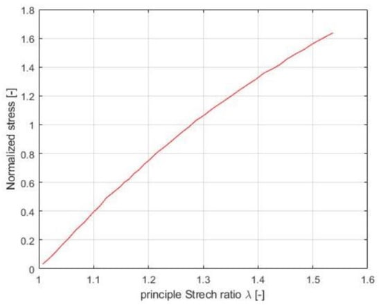
Figure 7.
Ogden model for brain tissue.
Because there is a dearth of detailed knowledge about modeling brain tissue, we have opted for the straightforward model shown in Figure 7. It is currently the only straightforward yet reliable model that is available to us. The necessity for simplicity and accuracy and the lack of more extensive modeling choices dictated this decision in the absence of alternatives.
The stretch ratio (λ) in our case is the position of the robot (x), which is same as the distance between the brain folds that we are opening because the initial position is taken as zero. The force is calculated with Equations (3)–(5).
A stiffness model from the literature is used to normalize the force to its maximum values. The maximum force is a necessary parameter for this model.
3. Control Proposal
Through a digital twin or a more intricate model than the one utilized in the earlier study, reinforcement learning (RL) enables adaptation.
Among the deep reinforcement learning techniques, we will use the Deep Deterministic Policy Gradient (DDPG). Both are included in the reinforcement learning (RL) paradigm.
RL is based on the fact that a robot, also known as an actor, can train itself to solve a problem and always executes the most appropriate decisions (which will give the greatest reward) [20]. RL’s actor is connected to a simulated environment, which defines the problem we want to solve. While training, the agent will select actions based on the feedback received from the environment. The goal is to gradually learn the set of actions that will give the actor the best reward by solving the problem with the optimal result.
DDPG uses this method to learn a policy (what to do in a given state or situation) in a continuous environment with a deterministic actor [21]. A problem formulation is composed of the environment, the agent (critic and actor), and the reward function.
The initial article’s methodology confines the development to a linear model of brain tissue. Because it incorporates control based on continuous input and output variables, this technique was chosen above others.
3.1. Environment
The environment gives the agent the information it needs, such as, the observations which define the state (position of the retraction tools and deformation force) and the reward (value of the previously taken action) (see Section 3.4) [20]. As stated previously, it is a simulated environment, which simulates the operation room and the brain. The code written to create the environment was divided into two parts.
On one hand, we initialized the quantity/number of observations and actions (see Algorithm 1). Then, we set all the values for all the variables that are necessary to perform the calculations within the environment, and finally created the environment.
Also, we created a function called “cleanstart” (see Algorithm 2), which reset all variables to their starting values, so that when a new simulation starts, the agent will start from the same state every time.
| Algorithm 1: Create an environment. |
|
| Algorithm 2: Create a reset function. |
|
On the other hand, we created a function that runs every time the agent interacts with the environment to give it feedback, where the actual position of the robot and the value of the deformation force are calculated (see Algorithm 3). In addition, the reward function is calculated and the ending/penalty conditions are checked, which will be explained later.
| Algorithm 3: Obtains observations and reward for agent use. |
|
| Algorithm 4: Terminal conditions. |
|
| Algorithm 5: Reward function. |
|
3.2. Agent
The agent in DDPG is composed of two parts, which were implemented as two neural networks.
3.2.1. Actor
The actor is the first neural network that we need to create. Neural networks learn from data sets to construct a model [19]. Neural networks are made up of several layers, each inner layer fulfilling a function. The layers are made up of a number of neurons, which are connected to the neurons of the layers before and after. Each neuron has weights and biases that define the neural network output and are variables that change while training. The consequence of these connections and weights is a long equation, filled with variables that implement our policy. Figure 8 shows a simple model.
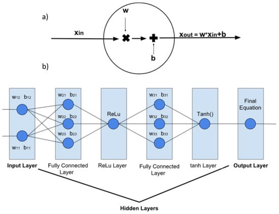
Figure 8.
Simple model of an (a) artificial neuron and (b) artificial neural network.
In reinforcement learning, the actor–critic architecture is a common approach used to solve problems where an agent interacts with an environment and learns to make decisions, in order to maximize its long-term rewards. The actor–critic architecture combines elements from both value-based and policy-based methods to improve learning efficiency.
The actor–critic architecture has several advantages:
- Efficient learning: The critic’s value estimates guide the actor’s exploration and exploitation, which helps in faster convergence and better decision-making.
- Policy optimization: The actor’s policy can be directly optimized using gradient-based methods, leveraging the critic’s value estimates. This allows for more flexible and effective policy updates compared to value-based methods alone.
- Handling continuous action spaces: The actor–critic architecture is well-suited for problems with continuous action spaces, where the actor can learn a policy that produces continuous valued actions, while the critic estimates the value of state–action pairs.
The actor is responsible for learning a policy, which is a mapping from states to actions. It directly interacts with the environment, receives observations, and selects actions based on its current policy. The actor explores the environment and collects data by performing actions and observing rewards and next states.
We build the following neural network for the actor. It is worth mentioning that we built a Multilayer Perceptron (MLP) artificial neural network that is usually composed of alternating Fully Connected Layers (layers composed of neurons that are connected with neurons in all previous and following layers) and ReLu Layers (layers that limit the data to only positive values).
The layers for the actor were:
- Input Layer (obs1) → 2 inputs/observations (x,F) → 2 neurons;
- Fully Connected Layer (fc1) → 10 neurons;
- ReLu Layer (relu1);
- Fully Connected Layer (fc2) → 10 neurons;
- ReLu Layer (relu2);
- Fully Connected Layer (fc3) → 10 neurons;
- ReLu Layer (relu3);
- Fully Connected Layer (act1) → 1 neuron;
- ReLu Layer (relu4) → works as the output layer → 1 neuron.
3.2.2. Critic
The critic is the second and final neural network that we need to create. The critic evaluates the actions taken by the actor by estimating the value or quality of each state or state–action pair. It provides feedback to the actor by estimating how good or bad the actor’s actions are in a given state. The critic learns from the collected experiences and updates its value estimates to guide the actor towards better actions.
To build the critic neural network, we used the following layers. We started with two different lines that converge into one since the critic takes inputs from two different sources, i.e., the environment and the actor.
- 1st Line:
- ○
- Input Layer (obs2) → 2 inputs/observations(x,F) → 2 neurons;
- ○
- Fully Connected Layer (fc1) → 10 neurons;
- ○
- ReLu Layer (relu1);
- ○
- Fully Connected Layer (fc2) → 10 neurons.
- 2nd Line:
- ○
- Input Layer (act2) → 1 input/observations. → 1 neuron.
- ○
- Fully Connected Layer (fact) → 10 neurons.
- Convergence Line;
- Addition Later → adds the two lines into one;
- ReLu Layer (relu2);
- Fully Connected Layer (fc3) → 10 neurons;
- ReLu Layer (relu3);
- Fully Connected Layer (value) → works as the output layer → 1 neuron.
After creating the actor and the critic, we combine them to create our complete agent.
3.3. Terminal Conditions
When we talk about terminal conditions, we refer to situations where the simulation enters a state that we cannot handle, which might be impossible in reality, or a state that we do not want to pass through it (see Algorithm 4). Are our terminal conditions are the following:
- The agent opens the brain more than desired, creating too much pressure.
- The positions have negative values. This is impossible in reality.
- While the robot opens the brain, the robot starts closing it again without reaching our objective, making us lose time.
If we encounter any of these situations, we will add a penalty to the reward, so that the agent can avoid them. Typically, in terminal conditions, rewards are given when our robot successfully reaches a specific goal. However, in our case, these rewards are not implemented because our objective is not simply to reach a specific value (e.g., opening until a certain threshold), but rather to sustain and maintain a desired state (keeping the brain open).
3.4. Reward Function
The reward function in reinforcement learning (RL) is a mechanism that assigns numerical values to different states or actions taken by an agent. It serves as a measure of the desirability or success of those states or actions, guiding the learning process of the RL algorithm by providing positive or negative reinforcement signals.
Therefore, the environment variables that will be observed and the following circumstances will be taken into account:
- The error is as small as possible.
- The opposite force made by the brain must be as small as possible.
- Speed should be as small as possible.
Knowing all of this, we established the following code.
The reward value function used in the code is described by Equation (6). The variable “Penalty” in the equation only takes on a value when a terminal condition is met (see terminal conditions in Section 3.3).
The equation provided represents a mathematical expression that was derived after extensive experimentation and iterations. Let us break down the components and their meanings.
- R within the equation signifies the system’s output, specifically representing the velocity of the robot.
- λ1, λ2, and λ3 are coefficients or constants embedded within the equation, ostensibly governing and shaping the intricate behavior of the system.
- λ1: This parameter governs the relative significance of both the position error and the reactive force within the reward function.
- λ2: This parameter controls the relative significance of the position error within the reward function.
- λ3: This parameter modulates the significance of the position error within the reward function.
- x and ẋ represent the state of the robot within the system, with x denoting its position and ẋ representing its velocity.
- F embodies the reactive force emanating from the brain, obtained through the Ogden model data elucidated in point 2. Our objective is to minimize this force.
- In the event that the terminal condition is satisfied, the Penalty variable introduces a penalty into the reward function. This serves to inform the actor that an unfavorable combination of actions was taken.
4. Experimental Results
Once we created the environment and agent, we started training the agent. We established the training parameters shown in Table 2.

Table 2.
Control parameters and variables in Equations (3)–(5).
In order to obtain successful results, the training settings provided in Table 3 have been chosen following a number of thorough trials. Fine-tuning parameters in reinforcement learning can frequently be a difficult operation that requires a rigorous process of trial and error. It is important to keep in mind that changing these settings can result in less-than-ideal outcomes. For example, when changing the learning rate, we saw occasions where the robot did nothing while training.

Table 3.
Training parameters.
As we can see in the training plot (Figure 9), the actions initially performed by the actor make no sense; however, as time passes, the reward is larger and larger, jumping at the end between the terminal condition of the upper limit and our desired position.
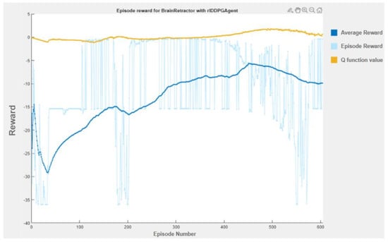
Figure 9.
Training plot.
We saved the best performing agent for testing later. The following figures show the performance of that agent. As we can see (Figure 10, Figure 11, Figure 12, Figure 13, Figure 14, Figure 15, Figure 16, Figure 17 and Figure 18), the agent has decided, with our established reward function, that the best option is to set the maximum speed at the beginning is and stop it once we achieve our desired position (xdesired). For all the cases, to change from one objective to another, we had to train our agent again.
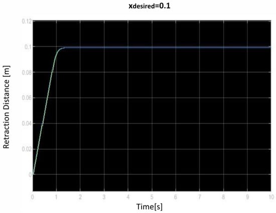
Figure 10.
First distance of retraction over time curve.
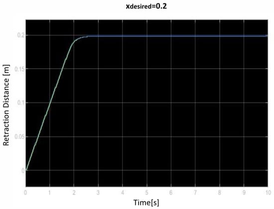
Figure 11.
Second distance of retraction over time curve.
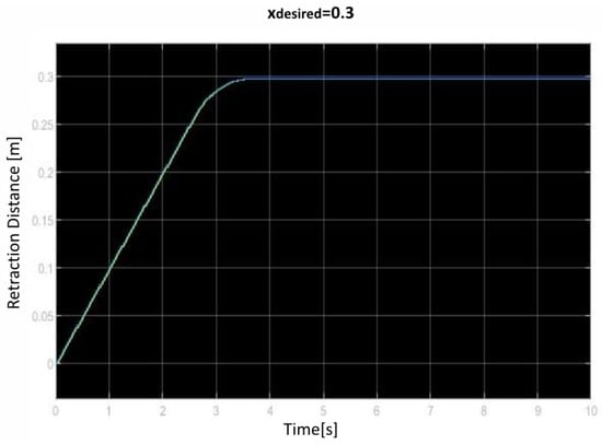
Figure 12.
Third distance of retraction over time curve.
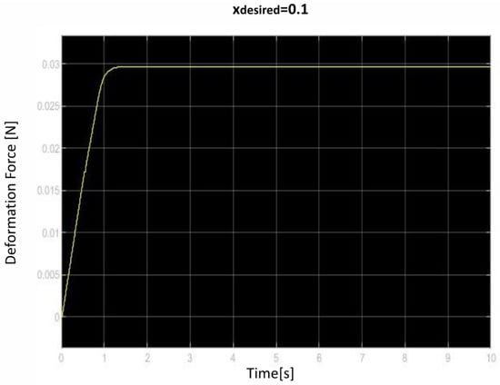
Figure 13.
First deformation force over time curve.
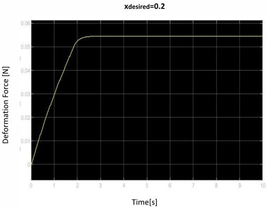
Figure 14.
Second deformation force over time curve.
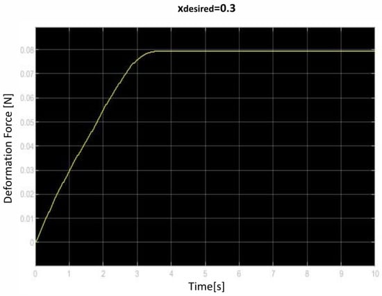
Figure 15.
Third deformation force over time curve.
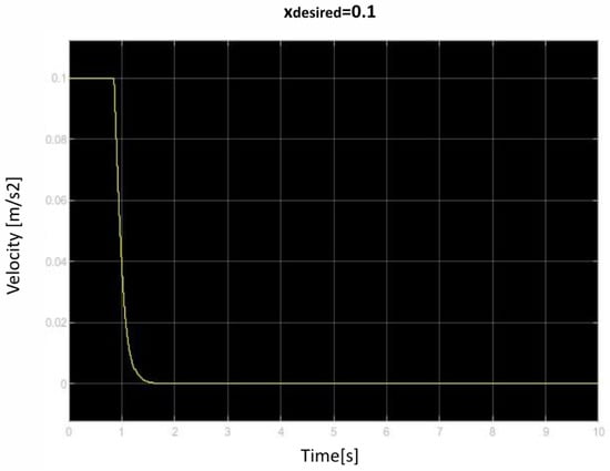
Figure 16.
First velocity of retraction over time curve.
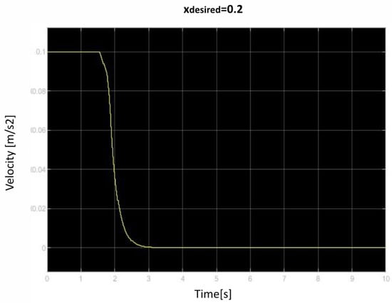
Figure 17.
Second velocity of retraction over time curve.
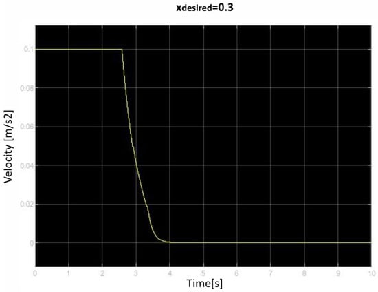
Figure 18.
Third velocity of retraction over time curve.
5. Conclusions
We followed the article [1] and used the knowledge given to create a control problem using deep reinforcement learning techniques.
This article’s primary contribution lies in its comprehensive guide for preparing an autonomous robot to effectively utilize the DDPG method. DDPG involves the establishment of two distinct networks, and this work plays a crucial role in elucidating their structural prerequisites and specifying the requisite transfer functions. Additionally, it introduced an incentive function designed to assist the robot in overcoming control challenges. Furthermore, it delved into the critical parameters and hyperparameters essential for training these networks. The central objective here is to assess the future potential of this system, with prospects for developing a more intricate model of the robot’s behavior. It is worth noting that the current work represents an initial application of the deep reinforced learning algorithm to address an existing problem, laying the foundation for future advancements in this domain.
As we can see, our results compared to the ones in [1] are not the same. The graphs of velocity over time do not match (Figure 3 and Figure 13). This is due to our reward function, which does not perfectly represent the actual problem and gives a similar explanation. For future improvement, the reward function could be adjusted (by changing the lambda coefficients) so both the agent self-training policies and calculated optimal speeds match.
The proposed control method operates as a closed-loop control, which has been tuned according to a reward function. Therefore, the input to the actor agent accepts both a position error and a measurement of the force exerted by the retractor. The output consists of the position/velocity of the retractor.
One of our biggest limitations is that even if we change the desired retraction distance after training, it will not change the robot’s behavior and will just function to retract the brain until the trained distance is reached. For every new desired retraction distance, the agent must be retrained. This can be improved in the future by training an agent for different xdesired values. This can be achieved by adjusting our reset function (Algorithm 2) and adding xdesired as a random variable that changes when a simulation starts. This was tested by us but was immediately thrown out due to lack of computational resources and time.
The availability of a linear or near-linear model adequately describing the mechanical properties of brain tissue is a prerequisite for the validity of the analytical strategy described in the initial study. This crucial realization emphasizes how important it is to continue studying and improving our understanding of brain mechanics since it has a direct bearing on the applicability and efficiency of analytical approaches to dealing with complicated problems in this area.
In our current state, the experiment cannot be tested in real-life situations. As soon as more complex models of mechanical behavior and brain damage become available, this technique can be applied directly. However, it is important to note that, in its current state, the experiment conducted cannot be tested in a real-life situation due to the simplicity of the models used and the need for a more accurate representation of reality.
When a more complex mechanical stress model of brain tissue is available, the technique used in this study enables improved control. It is adaptive in nature and can produce good outcomes when a more precise digital counterpart is present.
Author Contributions
Conceptualization, E.Z. and I.I.-H.; methodology, I.I.-H. and E.Z.; software, E.G. and I.I.-H.; validation, S.E. and U.F.-G.; formal analysis, S.E. and E.Z.; investigation, I.I.-H. and J.M.L.-G.; resources, U.F.-G. and E.Z.; writing—original draft preparation, I.I.-H. and E.G.; writing—review and editing, J.M.L.-G. and E.G. All authors have read and agreed to the published version of the manuscript.
Funding
The authors were supported by the government of the Basque Country through the research grant ELKARTEK KK-2023/00058 DEEPBASK (Creación de nuevos algoritmos de aprendizaje profundo aplicado a la industria). This study has also been conducted partially under the framework of the project ADA (Grants for R&D projects 2022 and supported by the European Regional Development Funds).
Data Availability Statement
Data are available upon reasonable request to the corresponding author.
Acknowledgments
The authors would also like to thank Karmele Gomez for her contribution. The authors wish to thank the Aldakin Group for material support. Finally, the authors thank the University of the Basque Country for its laboratory resource collaboration.
Conflicts of Interest
The authors declare no conflict of interest.
References
- Inziarte-Hidalgo, I.; Uriarte, I.; Fernandez-Gamiz, U.; Sorrosal, G.; Zulueta, E. Robotic-Arm-Based Force Control in Neurosurgical Practice. Mathematics 2023, 11, 828. [Google Scholar] [CrossRef]
- Dewan, M.C.; Rattani, A.; Fieggen, G.; Arraez, M.A.; Servadei, F.; Boop, F.A.; Johnson, W.D.; Warf, B.C.; Park, K.B. Global Neurosurgery: The Current Capacity and Deficit in the Provision of Essential Neurosurgical Care. Executive Summary of the Global Neurosurgery Initiative at the Program in Global Surgery and Social Change. J. Neurosurg. 2019, 130, 1055–1064. [Google Scholar] [CrossRef]
- Bennett, M.H.; Albin, M.S.; Bunegin, L.; Dujovny, M.; Hellstrom, H.; Jannetta, P.J. Evoked Potential Changes during Brain Retraction in Dogs. Stroke 1977, 8, 487–492. [Google Scholar] [CrossRef] [PubMed]
- Bell, B.A.; Symon, L.; Branston, N.M. CBF and Time Thresholds for the Formation of Ischemic Cerebral Edema, and Effect of Reperfusion in Baboons. J. Neurosurg. 1985, 62, 31–41. [Google Scholar] [CrossRef] [PubMed]
- Laha, R.K.; Dujovny, M.; Rao, S.; Barrionuevo, P.J.; Bunegin, L.; Hellstrom, H.R.; Albin, M.S.; Taylor, F.H. Cerebellar Retraction: Significance and Sequelae. Surg. Neurol. 1979, 12, 209–215. [Google Scholar] [PubMed]
- Andrews, R.J.; Bringas, J.R. A Review of Brain Retraction and Recommendations for Minimizing Intraoperative Brain Injury. Neurosurgery 1993, 33, 1052–1064. [Google Scholar] [PubMed]
- Spetzler, R.F.; Sanai, N. The Quiet Revolution: Retractorless Surgery for Complex Vascular and Skull Base Lesions: Clinical Article. J. Neurosurg. 2012, 116, 291–300. [Google Scholar] [CrossRef] [PubMed]
- Zagzoog, N.; Reddy, K.K. Modern Brain Retractors and Surgical Brain Injury: A Review. World Neurosurg. 2020, 142, 93–103. [Google Scholar] [CrossRef] [PubMed]
- Müller, S.J.; Henkes, E.; Gounis, M.J.; Felber, S.; Ganslandt, O.; Henkes, H. Non-invasive intracranial pressure monitoring. J. Clin. Med. 2023, 12, 2209. [Google Scholar] [CrossRef] [PubMed]
- Fukamachi, A.; Koizumi, H.; Nukui, H. Postoperative Intracerebral Hemorrhages: A Survey of Computed Tomographic Findings after 1074 Intracranial Operations. Surg. Neurol. 1985, 23, 575–580. [Google Scholar] [CrossRef] [PubMed]
- Kalfas, I.H.; Little, J.R. Postoperative Hemorrhage: A Survey of 4992 Intracranial Procedures. Neurosurgery 1988, 23, 343–347. [Google Scholar] [CrossRef] [PubMed]
- Rosenørn, J. The Risk of Ischaemic Brain Damage during the Use of Self-Retaining Brain Retractors. Acta Neurol. Scand. 1989, 79, 1–30. [Google Scholar] [CrossRef] [PubMed]
- Hoeckelmann, M.; Rudas, I.J.; Fiorini, P.; Kirchner, F.; Haidegger, T. Current Capabilities and Development Potential in Surgical Robotics. Int. J. Adv. Robot. Syst. 2015, 12, 61. [Google Scholar] [CrossRef]
- DeLorenzo, C.; Papademetris, X.; Staib, L.H.; Vives, K.P.; Spencer, D.D.; Duncan, J.S. Volumetric Intraoperative Brain Deformation Compensation: Model Development and Phantom Validation. IEEE Trans. Med. Imaging 2012, 31, 1607–1619. [Google Scholar] [CrossRef] [PubMed]
- Dai, Z. Improvement of General Design Theory and Methodology with Its Application to Design of a Retractor for Ventral Hernia Repair Surgery. Master’s Thesis, University of Saskatchewan, Saskatoon, SK, Canada, 2019. [Google Scholar]
- Yokoh, A.; Sugita, K.; Kobayashi, S. Clinical Study of Brain Retraction in Different Approaches and Diseases. Acta Neurochir. 1987, 87, 134–139. [Google Scholar] [CrossRef] [PubMed]
- Dujovny, M.; Wackenhut, N.; Kossovsky, N.; Leff, L.; Gómez, C.; Nelson, D. Biomechanics of Vascular Occlusion in Neurosurgery. Acta Neurol. Lat. 1980, 26, 123–127. [Google Scholar]
- Song, K.-Y.; Behzadfar, M.; Zhang, W.-J. A dynamic pole motion approach for control of nonlinear hybrid soft legs: A preliminary study. Machines 2022, 10, 875. [Google Scholar] [CrossRef]
- Coats, B.; Margulies, S.S. Material Properties of Porcine Parietal Cortex. J. Biomech. 2006, 39, 2521–2525. [Google Scholar] [CrossRef] [PubMed]
- Sutton, R.S.; Barto, A.G. Reinforcement Learning: An Introduction; MIT Press: Cambridge, MA, USA, 2018. [Google Scholar]
- Silver, D.; Lever, G.; Heess, N.; Degris, T.; Wierstra, D.; Riedmiller, M. Deterministic Policy Gradient Algorithms. In Proceedings of the 31st International Conference on Machine Learning, Beijing, China, 22–24 June 2014. [Google Scholar]
Disclaimer/Publisher’s Note: The statements, opinions and data contained in all publications are solely those of the individual author(s) and contributor(s) and not of MDPI and/or the editor(s). MDPI and/or the editor(s) disclaim responsibility for any injury to people or property resulting from any ideas, methods, instructions or products referred to in the content. |
© 2023 by the authors. Licensee MDPI, Basel, Switzerland. This article is an open access article distributed under the terms and conditions of the Creative Commons Attribution (CC BY) license (https://creativecommons.org/licenses/by/4.0/).