Article

Automatic Creation of 3D Documentation in CAD/BIM Based on Topology

by
Dalibor Bartoněk
Institute of Geodesy, Faculty of Civil Engineering, Brno University of Technology, 602 00 Brno, Czech Republic
Mathematics 2023, 11(17), 3758; https://doi.org/10.3390/math11173758
Submission received: 30 July 2023 / Revised: 21 August 2023 / Accepted: 28 August 2023 / Published: 31 August 2023

Abstract

:
This paper deals with reverse engineering, namely the as-built documentation of actual construction. The input is data measured in the field using geodetic methods. In addition to modern methods of surveying 3D objects, such as laser scanning, it is still necessary to use classic surveying using a total station. The bottleneck of the process is the creation of documentation of the construction, which is still created manually in the appropriate CAD/BIM software. The goal of this research was to find a method that would reduce the amount of manual work when drawing documentation in CAD/BIM to a minimum. The core of the solution is the use of a topology that interconnects the points measured in-field. The entire procedure has two parts: (1) creating a topological drawing template in a suitable CAD/GIS software (digital sketch) and (2) adding geometry to this sketch and creating a drawing using topological codes. This method was verified in practice by applying it to several specific buildings in the Czech Republic. The practical application of the method demonstrated 30% time savings and a reduction in work and error rate in the entire process.

1. Introduction

Today’s era is characterized by extensive digitization, which affects all fields. In the Czech Republic, digitization is supported by two fundamental strategies: Digital Czechia 2018+ [1] and GeoInfoStrategy 2020+ [2]. The goals of these strategies are the unification of all processes in the state administration and in the private sector, their subsequent automation and the storage of results in a central database for further use. In general, digitization is a complex process not only from a technical point of view, but also from an organizational one that requires fundamental changes in the legal, social and human resources fields. This article deals with digitization in the field of construction and geodesy in the issue of reverse engineering. It is a geodetic survey of the actual execution of the building in the field, processing the results in suitable software and creating a 3D model, or BIM (Building Information Modeling) [3] model. In practice, the following geodetic methods are usually used for surveying buildings:
  • Terrestrial surveying using a total station (spatial polar method);
  • Global Navigation Satellite Systems (GNSS)—primarily for the surveying network;
  • Laser scanning (terrestrial, airbone, mobile);
  • Photogrammetry (creating a 3D model using measurement images from cameras);
  • A combination of the above methods.
Focusing on the actual implementation of the construction is a necessary part of the life cycle of the construction before its commissioning. See Figure 1—here in the context of the resolved topic.
Currently, modern technologies such as laser scanning are most often used for the surveying of 3D objects. The advantage of this method is that in a short time we obtain geometric information about the object with a relatively high resolution (up to 1 mm); the disadvantage is the difficulty of processing and evaluating the obtained data. This is because it is a large amount of data (Big Data) that requires powerful hardware and sophisticated software. The main problem is the detection of edges in the cloud of points, which is a task that is difficult to algorithmize from the point of view of the mathematical theory of programs. The software used mostly works on the basis of heuristic methods with the support of artificial intelligence (classification, convolution, neural networks, etc.) [4]. Another problem is the transformation of the data into the global coordinate system (national grid). For this process, we need identical points with known coordinates that are missing in the point cloud. Experience from practice shows that both mentioned problems can be solved by a combination of geodetic methods, e.g., laser scanning + classical surveying or classical surveying + photogrammetry resp. classical surveying + GNSS. It follows from this fact that we cannot do without the classic orientation of a 3D object (building), even in the case of using modern technologies. However, the classic surveying of an object using a total station also has its problems. It is about creating a drawing from a set of points that were taken in-field. These points contain only the geometry of the object, lacking the topology that binds the points together. For this reason, until now the drawing of the 3D object in the appropriate CAD/BIM software was created manually, which is a time-consuming, tedious and error-prone job. The goal of this research was to find a method that would reduce the amount of manual work when drawing documentation in CAD/BIM to a minimum.
In the article, we will deal with the first mentioned method—i.e., terrestrial surveying of the building. The current procedure takes place in the following stages—see Figure 2:
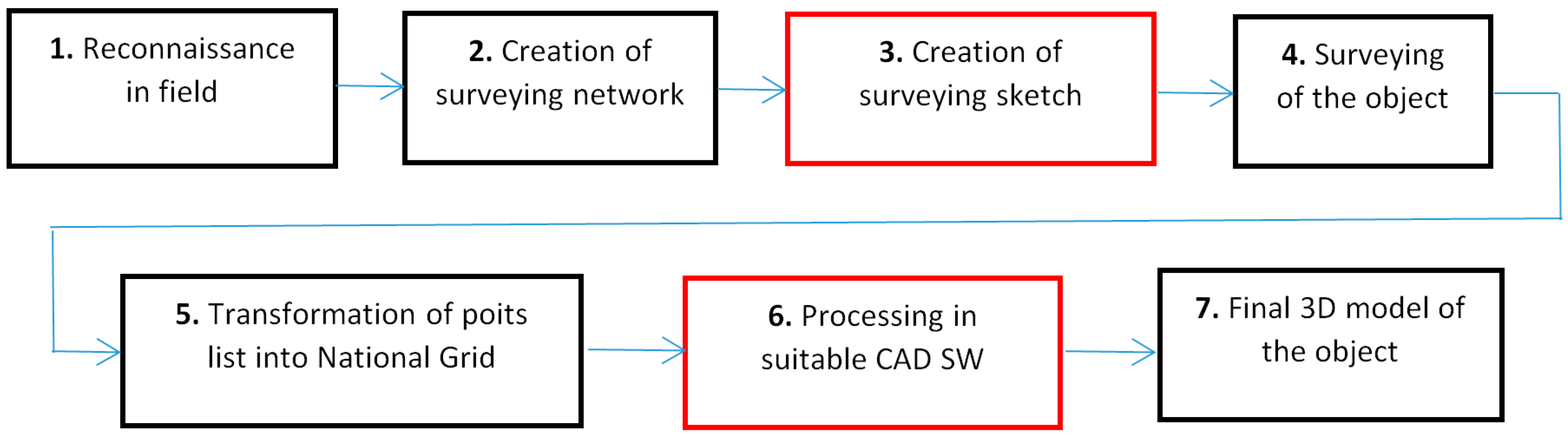
  • Reconnaissance in field with the identification of the position and height point field in the national grid.
  • Creation of a surveying network with the required accuracy of determining position and height in the reference system.
  • Creation of a surveying plan—a sketch of the object with the marking of the points that will be measured.
  • Surveying of the object (building) according to the sketch from the previous stage (3) using the spatial polar method. The output is a list of coordinates of points in the local coordinate system of the surveying network stored in the total station as a text file.
  • Import the text file into the appropriate software, where the point coordinates are transformed into the reference coordinate system. The output is a list of the coordinates of the measured points in the national reference coordinate system.
  • Import the list of point coordinates from the previous stage (5) into a suitable graphic CAD (computer-aided design) system, where the points are connected according to the sketch.
  • The output is a wireframe 3D model of the given object.
Figure 2. Phases during terrestrial surveying of a 3D object in field (building, structure) with highlighting of critical phases (red).
Mathematics 11 03758 g002
Current devices for terrestrial measurement use advanced technologies, which, in addition to the accuracy of the measured values, are characterized by a large number of built-in functions that provide high user comfort. Despite these advantages, however, a number of sub-processes during surveying must be carried out manually, primarily these two fundamental processes:
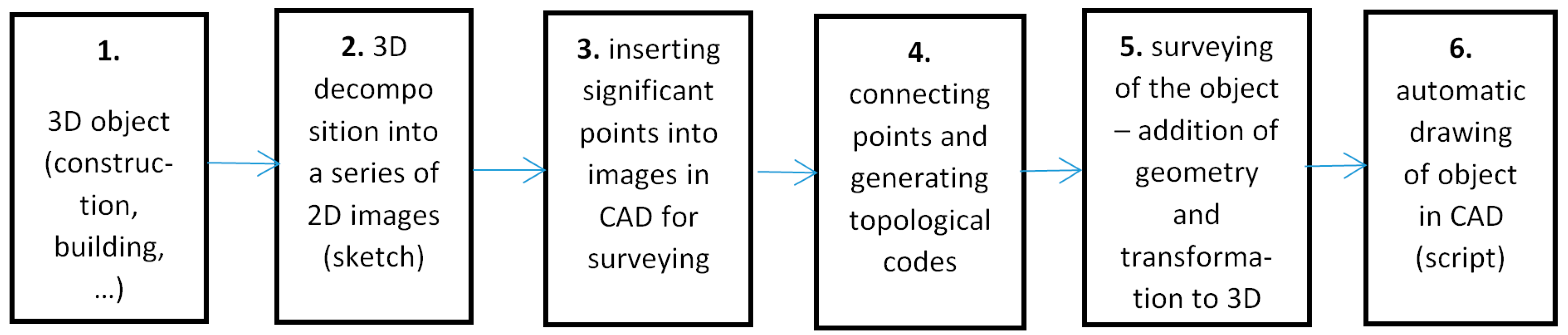
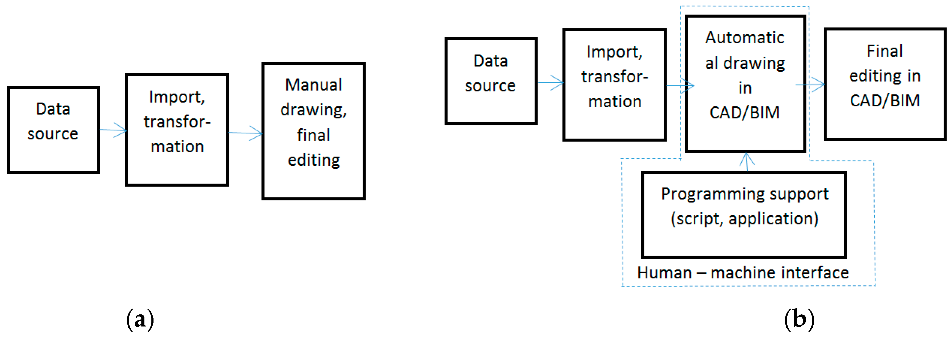
  • A measurement plan, i.e., a surveying sketch, which determines which points on the 3D object (construction) will be measured (item ad 3 in the above list of stages);
  • Connecting a set of focused points in the appropriate CAD/BIM software with lines and creating a 3D drawing in the CAD/BIM system for further processing (item ad 6 in the above list of stages). The BIM model can be understood as an extension of the CAD model with the necessary information that interprets graphic elements and is important for other processes in the construction life cycle (e.g., FM—Facility Management—in Figure 1, Operation).
The above-mentioned activities (measuring sketch and creation of a graphic drawing in CAD/BIM) are manually difficult and very time-consuming. For this reason, the processing chain, i.e., stages 1–6, is highly unbalanced and inefficient in terms of work and time requirements. The consequence of this fact is that, even with the use of high-performance technical and software tools, the resulting productivity of the actual design of the building is relatively low. For this reason, it is absolutely necessary to streamline the mentioned weak parts of the processing chain as much as possible so that the ratio of manual work is reduced to a minimum.
The goal of this article is to propose a method that would automate as much as possible both the measurement sketch and the creation of the resulting 3D drawing in the CAD system. This method is in accordance with both national strategies (Digital Czechia 2018+ and GeoInfoStrategy 2020+) mentioned at the beginning of the article.
Note: Many architects and designers often work in a local coordinate system. However, in context with digitization, it is desirable that they use the national grid so that their outputs are compatible with the related agendas of the state administration (Real Estate Cadastre Information System, GIS, etc.).
The article is organized as follows: in the Introduction section, the goal and need for the design of the new method are explained; in Section 2, scientific works on automated drawing in CAD systems are analyzed; in Section 3, the principle of the proposed method is described; the next Section 4 contains experimental results; and in the final Section 5, the contribution of the method is in brief summarized and evaluated.

2. Related Works

This article describes the method of automated drawing in CAD (e.g., AutoCAD 18/Revit) from data obtained by surveying of a real object (building) in-field. To connect the points, topological coding is used, which is created automatically from a digital sketch. The selection of related works, which were thematically divided into the following categories, corresponds to this goal:
  • General theory of topology and its use in CAD systems.
  • Automated drawing of a real object (reverse engineering).
  • Use of topology in 3D CAD graphics (drawing editing).
  • Automated drawing from existing data (mostly raster) and creation of a vector 3D model (vectorization).
  • Methods of transforming a hand drawing into a 3D CAD system.

2.1. Use of Topology in CAD Systems

In this category, the works of authors Sisi Zlatanova, Alias Abdul Rahman, Jatien Stoter, Chris Gold, Pawel Boguslawski, Hugo Ledoux and Claire Ellul [4,5,6,7,8,9,10,11] are considered the most outstanding. One of the most extensive works on topology in spatial data is article [5]. It is a summary of more than 147 works published so far. The results of the works are analyzed in terms of various criteria and contribute to a better understanding of spatial data in many industries. Work [6] contains a brief overview of the use of pragmatic topology in GIS (Geographical Information Systems). Work [7] deals with the topology of the interior spaces of buildings. It proposes a model for checking semantic, geometric and topological consistency of a reconstructed 3D model. The model is based on rules derived from current standards and expertise. A hybrid model based on topology and semantics for interior spaces is proposed in [8]. The topology, i.e., the connection of GO points, is implemented here using Delaunay triangulation. This method is used in the interiors of buildings in cases where information on 2D or 3D geometry and topology is missing. Topology in 3D GIS and spatial planning is dealt with in article [9]. Another work [10] analyzes the relationship between syntactic and semantic topology. It is about the classification of topology in n-dimensional space and the possibility of using the results in various applications. The relationship between syntactic and semantic topology in 3D is solved by work [11]. The authors proposed a special data structure for representing the interior spaces of buildings. This structure optimizes the storage of the model in memory. In work [12], the problem of Hausdorff distance in 3D CAD is solved. The authors propose two algorithms (with overlap, without overlap) that enable effective filtering of points in 3D and thereby simplify the processing of drawings in CAD.

2.2. Graphic in Reverse Engineering

The issue presented in publications [13,14] directly related to this article. It is about creating 3D models of buildings based on geodetic orientation in the field. Article [15] presents a program for surveying facades in CAD based on fractals and the box counting method. The core of this method is the search for topology in the geometry of the 3D model. Article [16] deals with reverse engineering in mechanical engineering. The topic is the reconstruction of machine components for CAD/CAM with a focus on the accuracy of approximation of shapes (detection of edges and surfaces). The parts are focused using terrestrial laser scanning. In general, the processing of point clouds from laser scanning belongs to the group of tasks that are difficult to algorithmize. The point is that a large set of points contains geometry, with minimal topology information. Topology is included in the point cloud only implicitly as a neighborhood of points. Therefore, any contribution in this area is very valuable. In work [17], a method of cutting a cloud of points is proposed using a previously obtained topology from a global model in order to preserve the continuity of individual cut parts. The method of least squares is used to approximate shapes.

2.3. Use of Topology in 3D Graphics in CAD

Works that deal with editing of an existing CAD drawing using topology are included in this category. A general overview of applications in CAD systems is presented in [18]. This article contains the history, brief development of CAD/CAM systems since the 1960s, used methods, programs and the perspective of further development of these systems. There is a widespread opinion among the professional public that it is impossible to find a topic that could be the subject of scientific research in the field of real estate cadaster. Article [19] refutes this assumption by proposing a method of mixed multilevel topological coding of 2D and 3D objects in the cadaster. Coding is made in the XML language and is used to define ownership relationships and create geometric plans (dividing and merging cadastral units—parcels in 2D and 3D). Topological encoding can have not only a substantive but also a procedural reason. The basic problem is the data transfer of 3D building models in a web (3D webGIS). The optimization method based on topological coding is presented in article [20]. With this method, each building is broken down into three basic structure types: main structure, independent structure and attached structure. Based on the links between the structures, a structural topology graph is compiled with the smallest unit for data transmission—the so-called transmission node. The principle of topology is also used in CAD in engineering. Work [21] presents the method of designing kinematic joint chains and their synthesis using graph topology. One of the modern methods of targeting buildings is laser scanning. Work [22] deals with the topology in the cloud of points for the needs of creating a BIM model. The continuity of walls of different shapes is investigated. This issue has not yet been satisfactorily resolved. The cloud contains geometry, but topology only in an implicit form (adjacency). If the points are adjacent, they do not have to be in a topological relationship (pragmatic topology). The topology of the drawing is dealt with in article [23], which proposes a topology-based 3D raster skeletonization algorithm. The principle is the detection of object and non-object points in an existing image. An important aspect of existing CAD and GIS datasets is copyright. In [24], the legally correct transfer of data sets and their use between actors in the processing chain of the given project is described.

2.4. Methods of Automatic Drawing in CAD

Topics related to automated drawing in CAD from various sources and using various methods (scanning, vectorization, artificial intelligence, etc.) are included in this category. Processing a point cloud from laser scanning is generally difficult and various methods are used. In work [25], an algorithm based on Delaunay triangulation is proposed, which creates a multi-resolution alpha-shape series. The final phase of the algorithm generates 3D printable models. Some CAD systems have a limited set of drawing functions and users have to program the necessary procedures themselves. In [26], an algorithm for finding the center and radius of a circle based on three geodetically oriented points is proposed. The script is stored in the module and is used to automatically draw arcs and circles from given points. Article [27] deals with the semi-automatic creation of building documentation in CAD. It is a method of creating a digital twin in the BIM model. The algorithm has three phases: (1) extraction of geometry (parts of the building) from CAD and OCR drawing, (2) addition of relevant information based on fuzzy image processing, and (3) creation of IFC format based on modules ad (1) and ad (2). In article [28], an algorithm is proposed for the automatic generation of CAD drawings in DXF format in the field of engineering. Work [29] presents a method of automatically creating assembly plans in engineering from a series of CAD drawings. This method is based on image recognition using artificial intelligence and pattern recognition. Work [30] presents a semi-automatic method of edge detection in a 3D point cloud. Edges are identified on 2D surfaces of known orientation and the algorithm determines the plane defined by the edge in the image and its perspective center. The goal is to locate points that form an edge in geodesic space. The automatic drawing of 2D floor plans of exterior and interior spaces of buildings is described in [31]. The algorithm is based on a heuristic search in the graph. The input is the topological plan structure of the resulting rectangular drawing. In article [32], a method of automatic dimensioning in CAD drawings is proposed. This method is based on modifying the properties of graphic elements and comparing them with similar drawings. Study [33] deals with the automatic drawing of biochemical networks based on the topology of nodes and the cost function between them. The algorithm is based on the method of simulated annealing. A similar problem is solved in [34]. It is about the automatic drawing of CAD diagrams in electrical engineering based on an expert system that searches for suitable elements from the database according to the topological graph. In work [35], a heuristic algorithm for the automatic drawing of flowcharts is proposed. The core of the algorithm is the conceptual design and topological structure of the system. The optimization of the planar graph is based on a heuristic method. The application uses special engineering symbols. The goal of the method described in [36] is to provide an automatic transformation of architectural CAD drawings into spatial and topological information about the building for further use. The basis of the algorithm is graph theory—a part of topology. The vectorization of aerial images based on topology extraction from these images is solved in [37]. The method was verified on images of cities and road networks. The original method of automatic 2D to 3D drawing conversion is described in [38]. This method is based on the simplification of a 2D drawing and its subsequent assembly into a hierarchical structure of a 3D model.
Article [39] evaluates the existing methods of reconstruction of models from CAD drawings. The algorithm is based on the boundary representation of the 3D model. The automatic generation of a 3D BIM model from a series of 2D CAD drawings is described in [40]. The method is based on the analysis of the floor plan of the building and creates a 3D model in BIM technology. Another method for automatic drawing is addressed in [41]. It is a drawing of lines from stereo photogrammetric images supplemented by a scanner. The normals of the relief surface are selected from the 2D images, which are transformed into 3D using the scanner projection.

2.5. Methods of Transforming a Hand Drawing into a 3D CAD System

Article [42] deals with the vectorization of raster images drawn with a pencil. The algorithm is based on the analysis of the topology of the drawing, especially where the lines cross. The topology calculation is performed using the gradient of the cluster of pixels in the centerline. The method of designing an automated drawing of a 3D CAD model based on scanning paper drawings is solved in [43]. An interesting method of automatic drawing of the interior of the building is proposed in article [44]. The drawing is generated based on a hand sketch using a special algorithm. The input of the algorithm is various variants of building shapes, including non-convex polygons. In article [45], a system of 3D tools for creating dynamic drawings is proposed. The method is based on the principle of seamless connection of a hand-made drawing of an object with a 3D model stored in the computer. The hand drawing is made by the user using the touch screen surface. Finally, the algorithm converts the drawing from 2D to 3D in real time. Another method for creating a 3D model from simple hand-drawn sketches is described in [46]. The method assumes the use of a priori knowledge about the object for the creation of its geometric model.
The common theme of the above-mentioned works is the effort to automatically support drawing in CAD/BIM systems and to solve related problems. The complexity of the methods proposed so far lies in the fact that in many cases they analyze the drawing as a whole, i.e., geometry including topology. This approach is already difficult to solve in 2D space, while in 3D similar problems are almost unsolvable (there is no effective algorithm). The next section describes a new method that simplifies the process of automated CAD/BIM drawing.

3. Method of Solution

3.1. Principle of the Proposed Method

In the processing chain in Figure 2, the blocks marked in red indicate processes of that are carried out manually, are very time-consuming and at the same time have a great influence on the efficiency of the entire process of surveying the building. Therefore, the goal of this research was to propose a method that reduced the proportion of manual work to a minimum in these processes and, if possible, automated the processes to the maximum extent possible. In essence, it is the digitization of two processes:
Creation of a surveying sketch (object measurement plan)—see block No. 3 in Figure 2;
Processing in suitable CAD/BIM software, especially the connection of individual points according to the surveying sketch—see block No. 6 in Figure 2.
The basic idea of the proposed method is formally described by the following equation:
S3 → {n × S2} → D2 D2T → D2T.G → M3
where
S3 is a set representing a 3D object in-field;
n × S2 means the decomposition of a 3D object into a series of 2D objects;
D2 is a selected set of points to be surveyed on the object;
D2T is set of points that have topology information (topological codes);
D2T.G is set of points that have information about topology and geometry, i.e., about the position of the point in the reference coordinate system (national grid);
M3 is a set of the resulting object (model) in digital form (CAD/BIM drawing).
The entire sequence of activities is shown in Figure 3. For the object in the real world, represented in block No. 1, a digital measurement sketch is created in the next phase. It is a series of digital images of the object in 2D, which are imported into a suitable CAD/BIM software—see block No. 2 in Figure 3. In this software, significant points with identification numbers are marked on all images that must be surveyed on the object. The points are inserted into the sketch in a special layer so that they clearly define the geometric determination of the 3D object—block No. 3 in Figure 3. In the next step (block 4 in Figure 3), these points are connected by lines, which are stored in the line vector layer. Then a special script is started that generates topological codes for each point. The output from block No. 4 is a list of points with topological codes, which is stored in a text file and serves as an input to the total station for surveying of the object.
This output is called a digital sketch, i.e., a set of images with marked points, which serves as a surveying plan in the next step. In block No. 5 in Figure 3, the object in the terrain is targeted using a digital sketch and a total station. During the measurement, the local coordinates of the point in the spatial polar method are added to each point. This list is then transformed from the local to the global coordinate system (national grid) in special software. The last process in Figure 3 is the automatic drawing from the list of coordinates of points with topological codes (topology + geometry) in the CAD/BIM system using a special script—see block No. 6 in Figure 3. The principle of topological coding and the algorithms of both scripts (for the digital sketch and the resulting drawing) is described in next subsections.

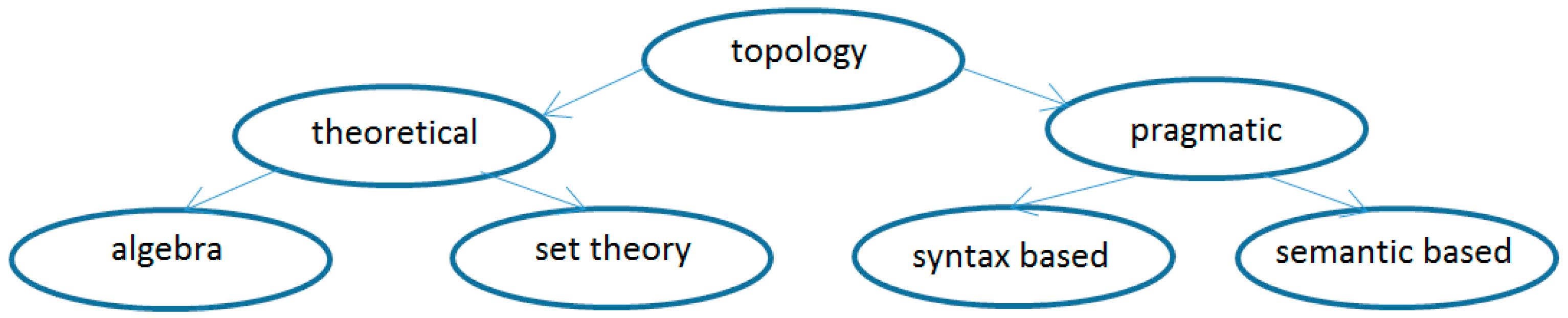
3.2. Topological Encoding

Many works have been devoted to topology in spatial structures, e.g., the already mentioned study [11] or other publications. Based on previous research, we can divide topology from the point of view of spatial data into two main categories and each of them into two subcategories—see Figure 4:
  • Theoretical—mathematical approach:
    a.
    An approach based on set theory. These mathematical theories are based on works devoted to the formal description and definition of types of topological relationships between spatial objects—see works [47,48,49,50,51,52,53,54], where each spatial object is viewed as a subset of the topological space (X, τx): X is a non-empty set, τx the system of all subsets of the set X.
    b.
    An approach based on algebra and combinatorics, which has found practical application in geoinformatics. It is about the theory of simplexes and simplex complexes. Based on this theory, spatial objects are classified according to their spatial dimension. For each dimension n, there exists a minimal object, which is called an n-simplex, where n indicates the spatial dimension [47,48,55,56,57].
  • Pragmatic—information technology approach:
Theoretical topology is characterized by high accuracy and detailed description. However, it is unsuitable for practical applications in GIS, as it would lead to time- and space-consuming algorithms. In discrete systems, a pragmatic topology is therefore used that has the advantage of simplicity and clarity compared to the theoretical topology. Pragmatic topology can be divided into:
a.
Syntax-based—topological entities (nodes, edges) are without further meaning.
b.
Semantic-based—topological entities represent specific geographic objects in the real world.
Syntactic topology was chosen for the coding of building objects, which is the simplest of the listed categories. In the case of semantic topology, we have to provide information about the meaning of a node, edge or surface for each entity. In syntactic topology, this information is not necessary; it is enough to define three basic topological concepts [58]:
  • Continuity of edges (edges are connected in topological nodes).
  • Area definition (a closed sequence of lines defines an area).
  • Adjacency (edges have a direction and define objects to the left and right).
Figure 4. Classification of topology in spatial structures.
Mathematics 11 03758 g004
The use of pragmatic topology significantly simplifies both the creation of a digital sketch and automated drawing in CAD. According to the DIGEST standard [58], there are 3 basic topological entities in pragmatic topology: nodes, edges and faces. Nodes represent points, which can be divided into geometric points—they only determine the shape and position of the entity, and topological points (intersections), which define the beginning or end of an edge. Since each point in the coordinate list has a unique identifier, it is not necessary to code it separately. We can use a code for a separate point if we assign it semantics (e.g., a point that represents a pillar or a tree in the terrain). The edges in the topology represent lines in the real object, which, of course, we have to code. For each edge, we need to determine its start and end node. We can simplify the coding of the site by adding a special character to close this chain of lines at the last end point of a series of lines. Based on the above considerations, we can propose a topological encoding according to the following rules:
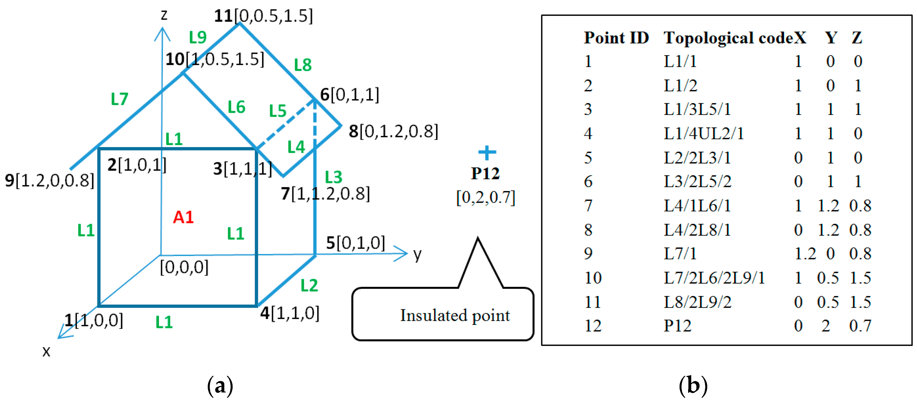
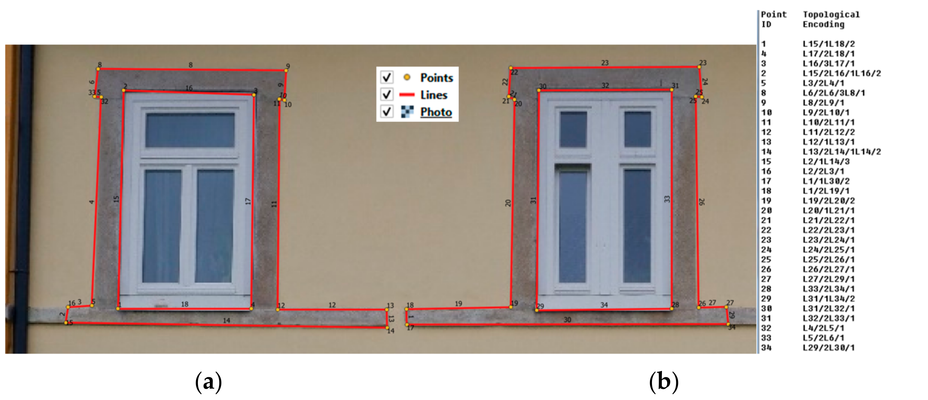
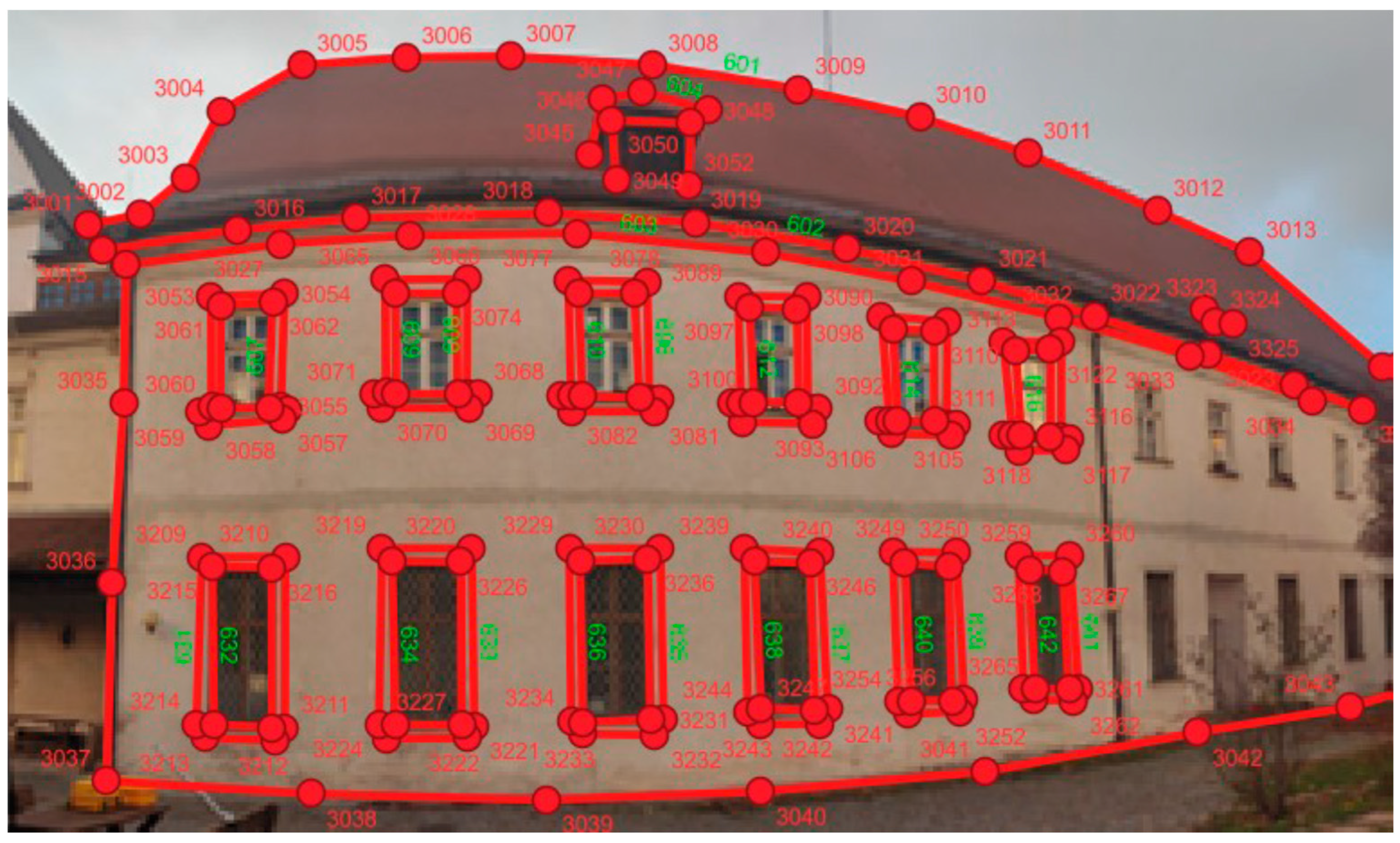
  • For isolated points, we use the symbol “P”—(point) with a numerical designation. This designation is used for semantics (e.g., column, tree, etc.). Points that are part of a line only have an ID (without a “P” symbol).
  • For lines we use the designation “LX”: “L” = line, “X” = numerical line identifier.
  • Each point on the line is marked with the sequence “LX/Y”, where “Y” is the sequence number of the point on the line. The point with the lowest ordinal number is the starting point of the line, the point with the highest ordinal number is the end point of the line and the other points are just geometric points of the line. Ordinal numbers are integers: they do not have to start from 1, nor do they have to form a complete sequence—there can be, for example, this form: (5–12–28–40) → (L1/5–L1/12–L1/28–L1/40).
  • Areas are defined implicitly in such a way that the lines that form the boundaries of the area have the same identifier and at the last point of the series of lines there is a “U” symbol in the code for the closure of the sequence of lines; see Figure 5. Areas have the code “AX”, where “A” = area “X” is the identifier of the area.
The situation is shown in Figure 5. The left part shows a 3D object with marked points and one isolated point (P12). Lines with their identifiers are also marked. The object contains one area—A1, which is defined by a sequence of lines L1 with the closure sign U at point No. 4. The second part of Figure 5 contains a list of all points with topological codes and geometric coordinates in the local coordinate system. This list contains all the necessary information to automatically draw the image on the left in a suitable CAD/BIM system using a special script. For speeding up and simplicity, the image is described without semantics and with implicit entity attributes. Further editing of the drawing is completed by the user in the CAD/BIM system.

3.3. Automated CAD Drawing Support

The list of points with topological codes and coordinates (Figure 5b) can be considered as a general and formal description of the graphics of the given 3D object. In this context, there are 2 problems need to be solved:
  • The process of creating topological codes and creating a digital sketch;
  • Automated drawing of a 3D object from a list of points (Figure 5b).
Ad (1) manual creation of topological codes in 3D is time-consuming and error-prone. Therefore, a semi-automated support was designed with the help of a special script. Reducing the difficulty of creating a digital sketch is achieved by:
  • Transformation from 3D to a series of 2D images of the object, thereby simplifying the solved problem;
  • By importing images into the CAD system and marking the topology by connecting points with lines. The created layer of points and layer of lines is processed with a special script that generates the topological codes of the entire object in a list—see Figure 5b.
The algorithm of a special script for creating topological codes in a suitable CAD/GIS system is presented in the following text.
The output of this Algorithm 1 is a list of points with topological codes for a 3D object. This list is saved in a text file and it serves as a plan for geodetic measuring the object in-field.
Algorithm 1. Topological encoding
Input: snaps series of 3D object into CAD/BIM/GIS
Output: text file—points list with topological codes
Initialization:
     create vector point layer, vector line layer, vector polygon layer
     create points_list, lines_list, polygons_list
     define items separator (space, ‘,’, ‘;’, TAB, …)
for all snaps do:
     insert points into all snaps → store in point layer
     connect points with lines → store in line layer
     draw areas on snaps → store in polygon layer
end
for all vector layers do:
     while exists non—processed point do:
         point → store ID to points_list
         if isolated point then: generate code and → store point ID + code to points_list
end
while exists non—processed line in lines_list do:
     for each line in lines_list with ID do:
         find start point, next points and end point of the line in points_list:
         generate order number in these points sequence along line
         generate topological code (Figure 5b) → store to the current point in lines_list
     end
end
while exists non—processed areas in polygons_list do:
     for each polygon in polygons_list with ID do:
         find all points of the polygon in polygons_list:
         generate order number in these points sequence
         generate topological code → store to the current point in polygons_list
     end
end
for all items in points_list, lines_list, polygons_list:
     write items into text file
end
The next step is the surveying of the object in terrain—see block no. 5 in Figure 3. This process is in fact a transformation of a series of measurement sketches, represented by a list of coordinates with topological codes from 2D to 3D space. The coordinates of individual points in the list are initially in the local coordinate system; see Figure 5b. The object is measured using the spatial polar method.
After the work in-field, it is necessary to transform the coordinates of the points from the local to the global coordinate system—S-JTSK (national grid of the Czech Republic).
The transformed list of point coordinates with topological codes stored in a text file contains all information about the 3D object in digital form. This file is imported into a suitable CAD/BIM/GIS software, where it is automatically drawn using a special script. The script is described below as Algorithm 2.
Algorithm 2. Automatic drawing from coded points list
Input: txt file with points list with 3D coordinates and topological codes into CAD/BIM/GIS
Output: Drawing in CAD file (DXF file)
Initialization:
     create vector points layer, vector line layer, vector polygon layer
     points from text file → store into points list (without duplicity)—list_P
     lines from text file → store into line list (without duplicity)—list_L
     polygons from text file → store into polygon (area) list (without duplicity)—list_A
while exists non—processed insulated point in list_P do:
     point → draw insulated point into points layer
     next point
end
while exists non—processed line in list_L do:
     for each line with ID do:
         find start point, next points and end point of the line:
         order these points according theirs order number → store points into list_L
         while exists line in list_L do:
             line → draw line into line layer
             if last point has symbol “U” do:
                 generate line between this point and start point (close area)
                 line → draw line into line layer
             end
         end
     next line
end
while exists non—processed polygons in list_A do:
     polygon → draw into polygon layer
     next polygon
end
convert whole drawing into DXF file in current CAD/BIM/GIS
end

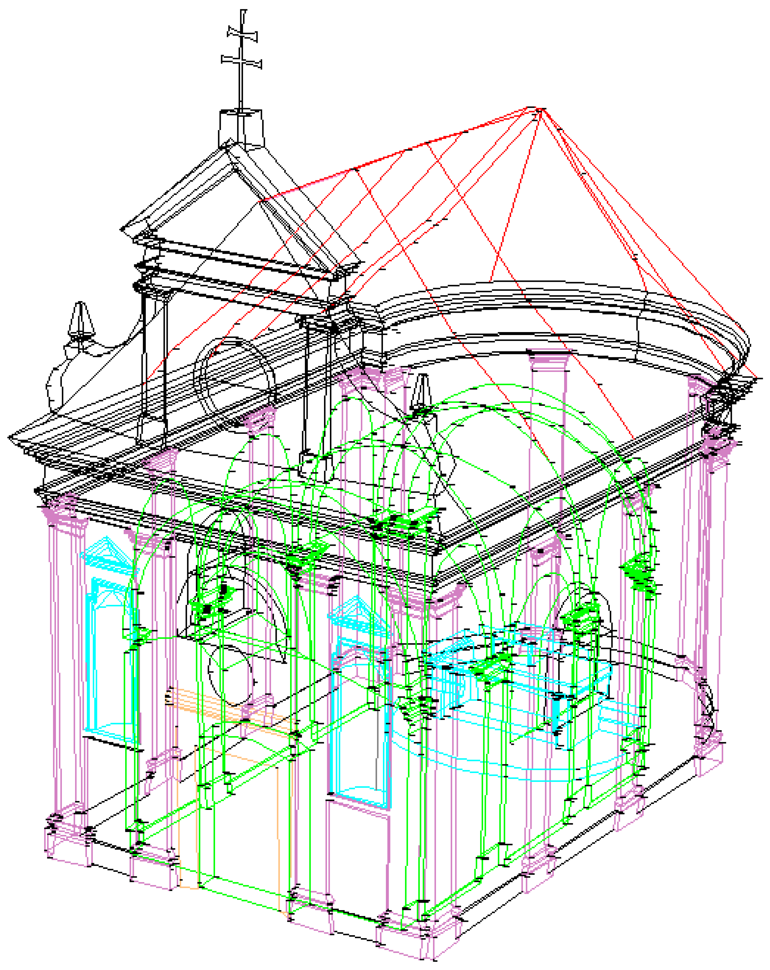
4. Experimental Results

The proposed method was verified on several construction sites in the Czech Republic. Two demo examples were selected for this section:
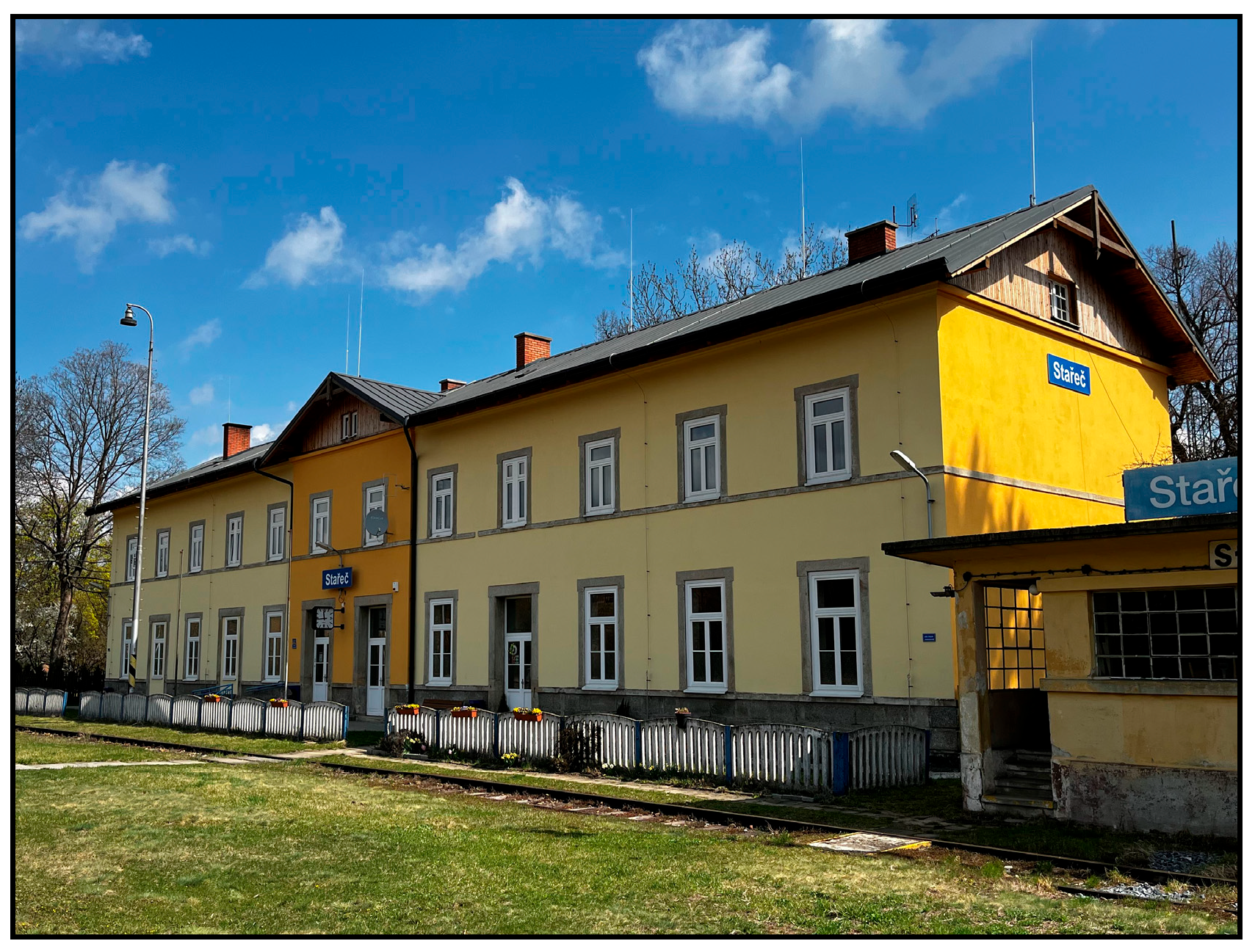
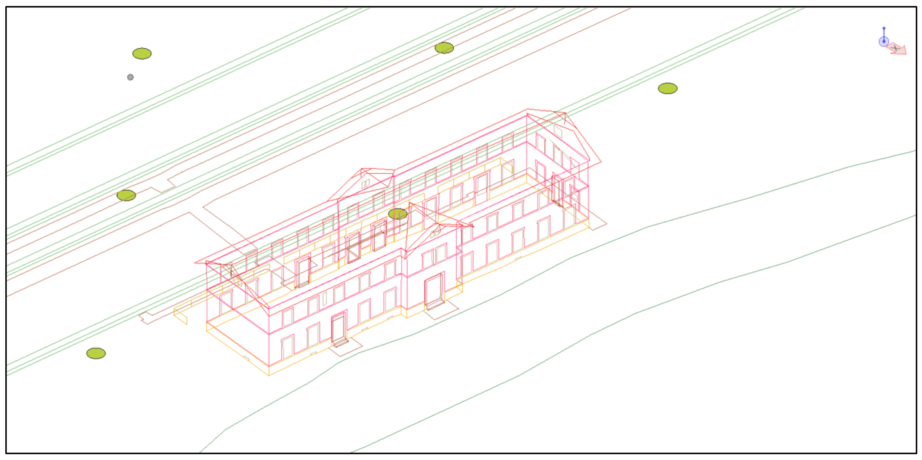
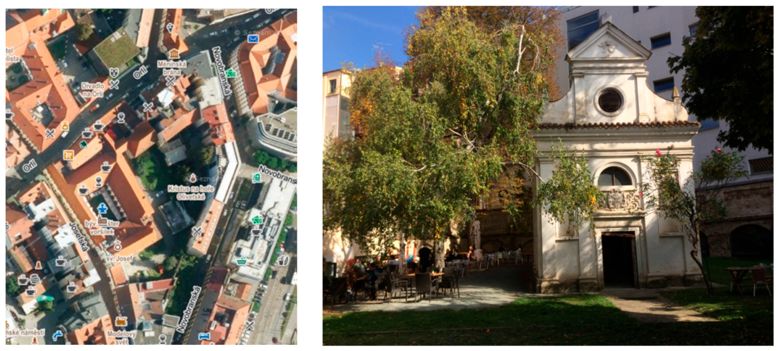
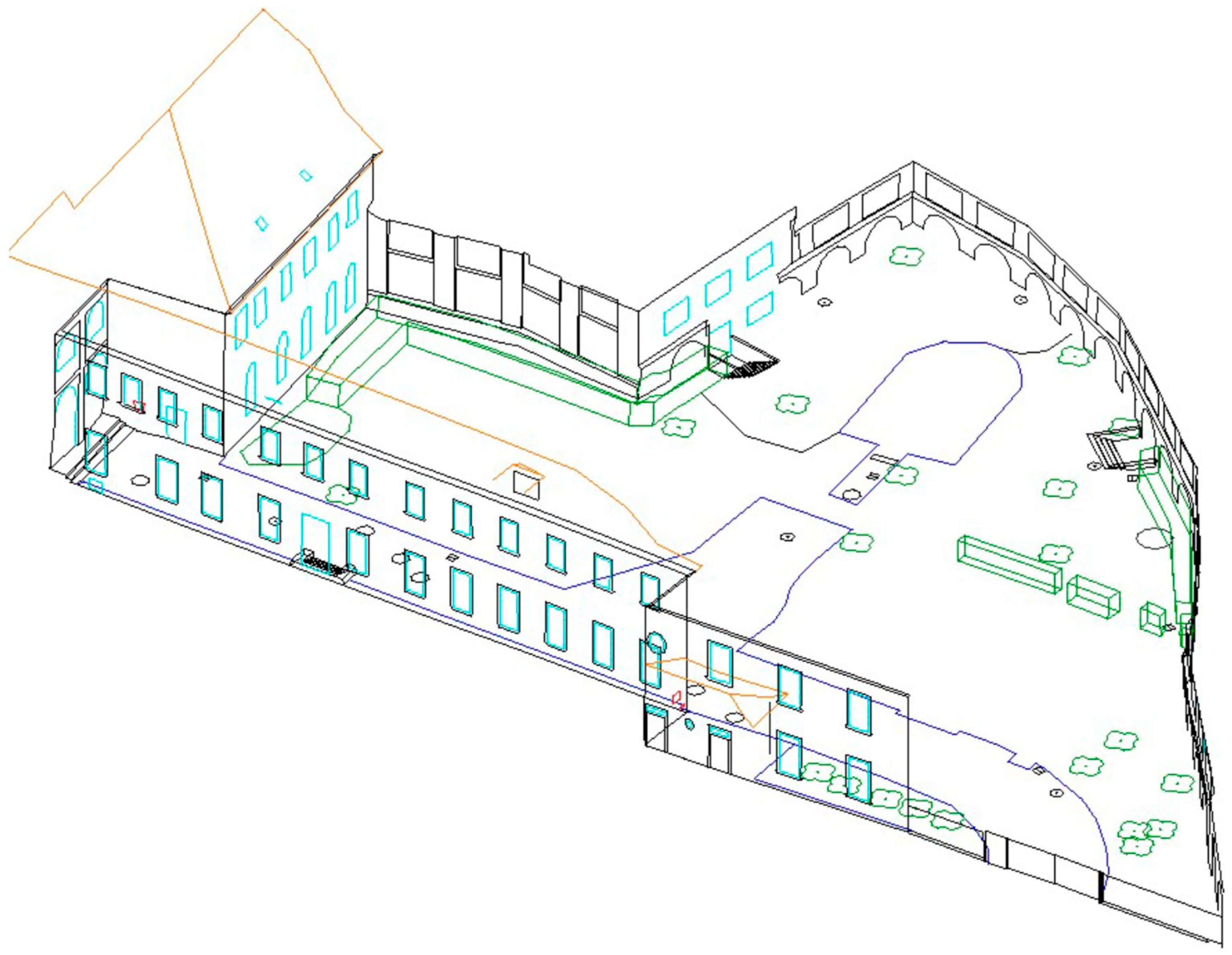
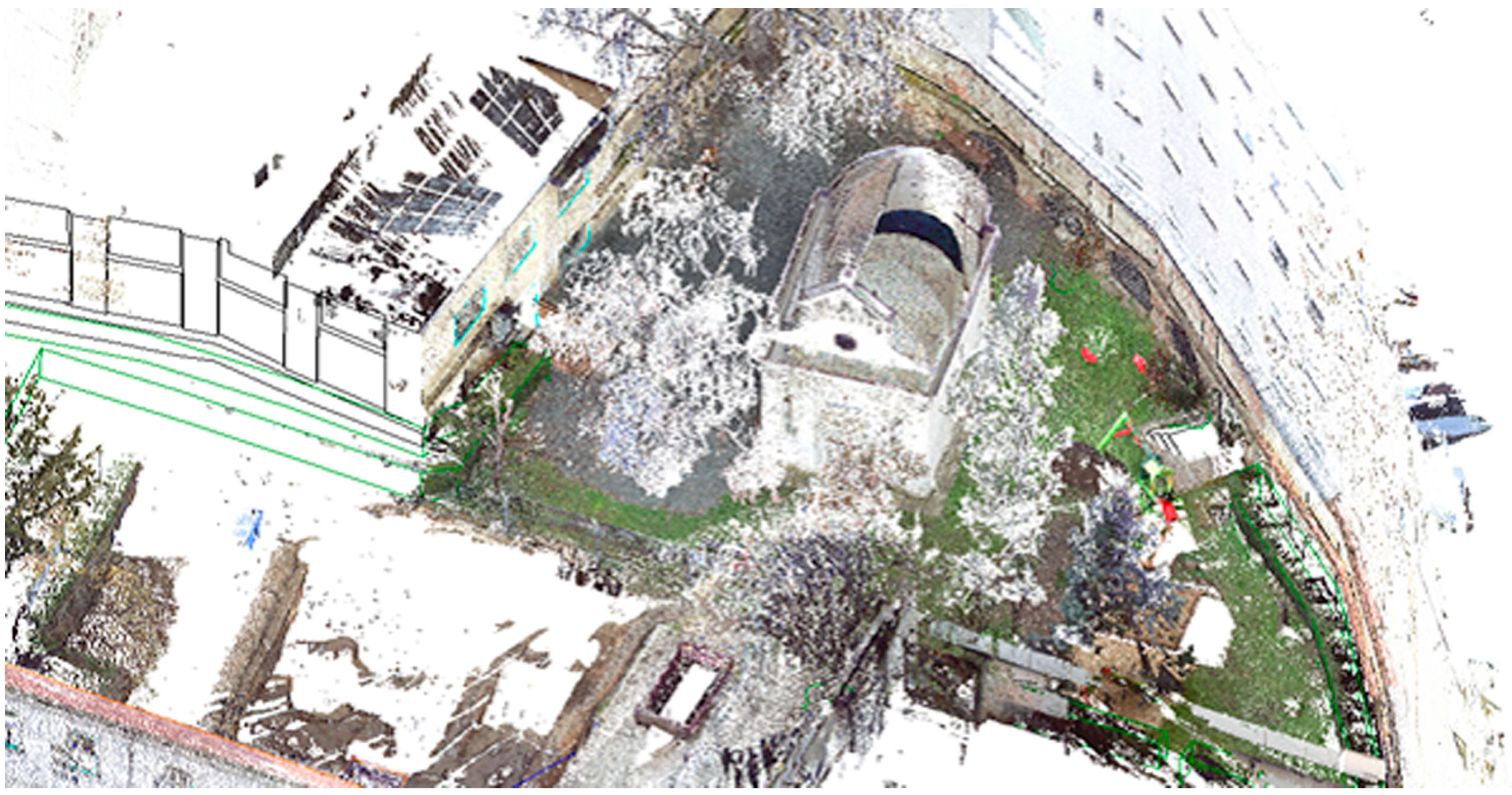
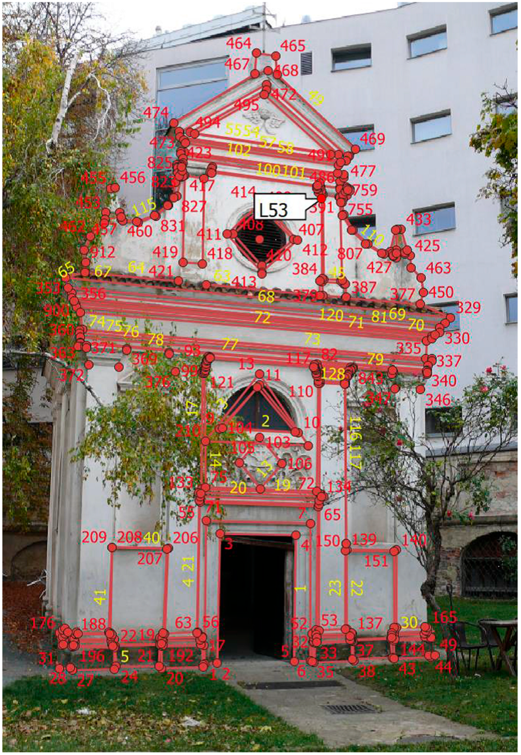
  • The station building in Stařeč, which was completely targeted using the proposed method of topological coding [59].
  • The surveying of St. Ursula’s convent with the chapel in Brno [60,61].

Surveying and Creation of Documentation for the Station Building in Stařeč

First, a series of photos of the building was taken; see Figure 6. The images were imported into QGIS where two vector layers were created: a point layer and a line layer. Points to be geodetically measured in terrain were inserted into the points layer. Then the points in the line layer were connected with lines according to the photo. In this activity, the accuracy of the position of points and lines does not matter; only the capture of lines to points (continuity) matters.
After completing the digital sketch (see Figure 7a) the Python script (v. QGIS 3.xx) was started that implements algorithm 1 in Section 3.3. This script creates a list of points with topological codes (see Figure 7b). This list is saved to a text file.
A text file with a list of points and topological codes was imported into the total station, which was used for surveying of the building object. During geodetic measuring, the actual coordinates of the points in the local coordinate system are added to the list, which is transformed into the national grid in the appropriate software. The resulting text file is the input to the Python script (see Algorithm 2), which automatically creates a drawing of the focused station building in the QGIS application. The final drawing is converted to * .DXF format and imported into a suitable CAD/BIM (e.g., AutoCAD 2018/Revit) software, where it can be edited—see Figure 8. For comparison: without topological coding, the drawing of relevant points would look like Figure 9. Connecting points was performed manually according to a paper sketch, which was a very work- and time-consuming activity in 3D.
Another structure on which the proposed method was verified is St. Ursula’s convent with the chapel in Brno [60,61]; see Figure 10.
The outputs from this project are in the next pictures. He Figure 11 is a Digital sketch of St. Ursula’s convent (zoom) [60], Figure 12 presents a wireframe model of St. Ursula’s convent (automated drawing), on Figure 13 is a wireframe model of St. Ursula’s convent combined with laser scanning (point of clouds), Figure 14 shows a digital sketch of the chapel [61], in Figure 15 is a wireframe model of the chapel and in Figure 16 is a wireframe model of the chapel with the combination of point clouds.
From the examples given, it is clear that the optimal method for surveying 3D objects (buildings) is currently a combination of classic surveying methods using a total station with one of the modern methods (laser scanning, GNSS, photogrammetry). This combination uses the advantages of the mentioned methods and greatly eliminates the disadvantages of using these methods alone (without combination).
A comparison of both methods is in Table 1, from which it can be seen that the new method saves about 30% of the total processing time.
Other objects were already subjected to the proposed method, and experience confirms the data in Table 1. The buildings listed in this section serve as demonstration examples.

5. Discussion and Conclusions

A method of automated drawing of documentation based on the geodetic surveying of the object was proposed. The main contribution of the proposed solution can be summarized in these three points: 1. The method of solving a complex problem by reducing the dimensions (here from 3D to 2D), solving the problem in a lower dimension and back-transforming the result into a higher dimension. 2. Automated drawing based on topology definition (digital sketch), supplemented with geometry. 3. Human–machine interface design for automatic CAD/BIM drawing using a combination of the above methods.
The time-consuming processes ad (3) and ad (6) in Figure 1, which are performed manually, are automated. Both processes are implemented using Python scripts in the QGIS application.
The result of the field survey is a list of point coordinates with topological codes, which is imported into QGIS. After that, a special script in the QGIS application automatically generates a drawing of the object (Figure 8). The next step is the conversion from the drawing to DXF format and final processing in a suitable CAD system (here in MicroStation). The method was verified on the Railway Station Building in Stařeč and St. Ursula’s convent with the chapel [59,60,61] and other buildings in the Czech Republic.
The practical application of the method showed a time savings of approx. 30% in the entire processing chain; see Table 1. There are several applications (e.g., MGEO in MicroStation) that use semantic topological coding, i.e., each edge has its own meaning, e.g., wall, piping. The problem is that these codes have to be created by the user manually (the algorithm cannot know what the meaning of a given edge is). The list of codes is usually extensive and the user has to search it in a complicated way. The proposed solution is simpler because it uses a syntactic topology and the semantics is determined by the user only in the CAD/BIM software. In addition, the user does not need to know the codes; they are automatically generated by Algorithm 1.
The proposed solution has an advantage over the previously used procedure in that the user draws the lines only once and simultaneously creates a digital topology using coding, which is used for automatic drawing. In the case of manual drawing on paper, the user must also connect the points in the CAD/BIM software—i.e., twice in total. Moreover, manually connecting points in CAD/BIM is very demanding work.
The proposed method solves a problem in the field of reverse engineering, where the actual documentation of buildings is mainly obtained manually with minimal automated support (libraries of elements). Although laser scanning and satellite measurement methods have recently been preferred—[62,63]—practice has confirmed that these methods cannot do without the classic measuring by total stations.
The method is also an inspiration for the development of the theory of CAD systems (direct engineering). One of the possible solutions in design theory is a formal description of the topology of the proposed object and subsequent transformation of the object into its specific geometry (display in a valid coordinate system).
Another advantage of the method is that the user does not need to know the coding technology or the format of topological codes—the encoding is hidden.
For easier creation of a digital sketch, we recommend arranging photos of the object systematically, either linearly (strip of images) or horizontally (images arranged in tiles). This simplifies the continuity of the numbering of detailed points and the insertion of lines (topology definition) in the appropriate software (here QGIS).
When creating a digital sketch, the geometry (position, distance) of the points does not matter; only the links between the individual points are important.
Practical use:
After editing in QGIS, the line layer is turned off and only the point layer and the snaps layer are printed, and the resulting document serves as a measurement plan in-field. This simplifies the orientation when aiming the object. When using a total station with a camera, a digital sketch can be used directly when aiming at a given point, thereby eliminating the constant switching of the user’s view between the sketch and the device. This leads to an increase in the efficiency of the entire measurement process in the field.
Contribution to theory:
We propose a new method—automated CAD/BIM drawing (direct engineering). For our motivation and contribution to general CAD theory (usable also in BIM technology), see Figure 17, Human–Machine Interface. Note: Figure 17b shows only the most important processes related to the given topic.
A new concept in surveying was introduced: “digital sketch”, which is a list of detailed points of the object with information about the topology. The actual geometry is assigned only after surveying in-field. The digital sketch thus represents a class of similar objects in the real world (topological template), which differ from each other only in geometry.
The proposed method is also a general contribution to digitization—[1,2]. A similar problem was solved in cartography [64,65]. In the further continuation of the project, the possibility of automatic or semi-automatic detection of points, lines and areas directly in the images of the targeted object will be solved.

Funding

This article was written with the support of Brno University of Technology specific research project Nr. FAST-S-22-8035 “Research on the use of GIS and BIM technologies in the processes of digitalization of the life cycle of buildings”.

Data Availability Statement

No data are available.

Conflicts of Interest

The author declares no conflict of interest.

References

  1. Available online: https://www.digitalnicesko.cz/ (accessed on 1 January 2013).
  2. Available online: https://www.mvcr.cz/clanek/geoinfostrategie.aspx (accessed on 1 January 2019).
  3. Available online: https://www.ukbimframework.org/ (accessed on 1 January 2012).
  4. Mansour, M.; Martens, J.; Blankenbach, J. Hierarchical SVM for Semantic Segmentation of 3D Point Clouds for Infrastructure Scenes. Preprints 2023. [Google Scholar] [CrossRef]
  5. Zlatanova, S.; Yan, J.; Wang, Y.; Diakité, A.; Isikdag, U.; Sithole, G.; Barton, J. Spaces in Spatial Science and Urban Applications—State of the Art Review. ISPRS Int. J. Geo-Inf. 2020, 9, 58. [Google Scholar] [CrossRef]
  6. Herbei, M.V.; Herbei, R.C.; Radulov, I. Topology of spatial data. In Proceedings of the 15th International Multidisciplinary Scientific Geoconference (SGEM), Albena, Bulgaria, 18–24 June 2015; Volume II, pp. 1175–1181. [Google Scholar]
  7. Nikoohemat, S.; Diakité, A.A.; Lehtola, V.; Zlatanova, S.; Vosselman, G. Consistency grammar for 3D indoor model checking. Transactions in GIS. Viley 2021, 25, 189–212. [Google Scholar] [CrossRef]
  8. Jamali, A.; Rahman, A.A.; Boguslawski, P. A Hybrid 3D Indoor Space Model. Int. Arch. Photogramm. Remote Sens. Spat. Inf. Sci. 2016, XLII-2/W1, 75–80. [Google Scholar] [CrossRef]
  9. Ellul, C.; Haklay, M. Requirements for Topology in 3D GIS. Trans. GIS 2006, 10, 157–175. [Google Scholar] [CrossRef]
  10. Ohori, K.A.; Ledoux, H.; Stoter, J. An evaluation and classification of nD topological data structures for the representation of objects in a higherdimensional GIS. Int. J. Geogr. Inf. Sci. 2015, 29, 825–849. [Google Scholar] [CrossRef]
  11. Goudarzi, M.; Asghari, M.; Boguslawski, P.; Rahman, A.A. Dual half edge data structure in database for big data in GIS. ISPRS Ann. Photogramm. Remote Sens. Spat. Inf. Sci. 2015, II-2/W2, 41–45. [Google Scholar] [CrossRef]
  12. Zhang, D.J.; He, F.Z.; Chen, Y.L. An efficient approach to directly compute the exact Hausdorff distance for 3D point sets. Integr. Comput.-Aided Eng. 2017, 24, 261–277. [Google Scholar] [CrossRef]
  13. Bartoněk, D.; Buday, M. Problems of Creation and Usage of 3D Model of Structures and Theirs Possible Solution. Symmetry 2020, 12, 181. [Google Scholar] [CrossRef]
  14. Bartoněk, D. Automatic drawing from point list using topological codes. Arab. J. Geosci. 2020, 13, 1131. [Google Scholar] [CrossRef]
  15. Lorenz, W.E. Fractal Geometry of Architecture Implementation of the Box-Counting Method in a CAD-Software. In Proceedings of the 27th Conference on Education and Research in Computer Aided Architectural Design in Europe, Istanbul, Turkey, 16–19 September 2009; pp. 697–704. [Google Scholar]
  16. Kovacs, I.; Varady, T.; Salvi, P. Applying geometric constraints for perfecting CAD models in reverse engineering. Graph. Models 2015, 82, 44–57. [Google Scholar] [CrossRef]
  17. Qiu, Y.J.; Zhou, X.H.; Qian, X.P. Direct slicing of cloud data with guaranteed topology for rapid prototyping. Int. J. Adv. Manuf. Technol. 2011, 53, 255–265. [Google Scholar] [CrossRef]
  18. del Cano, A.; de la Cruz, M.P.; Solano, L. Computer-aided design, engineering, manufacturing and construction: Evolution and future challenges. Inf. Constr. 2007, 59, 53–71. [Google Scholar] [CrossRef]
  19. Thompson, R.J.; van Oosterom, P.; Soon, K.H. LandXML Encoding of Mixed 2D and 3D Survey Plans with Multi-Level Topology. ISPRS Int. J. Geo-Inf. 2017, 6, 171. [Google Scholar] [CrossRef]
  20. Dong, J.W.; Tan, J.Z.; She, J.F. Structure-Level 3D Building Model Encoding Method for Progressive Transmission. ISPRS Int. J. Geo-Inf. 2021, 10, 306. [Google Scholar] [CrossRef]
  21. Zou, Y.H.; He, P.; Pei, Y.L. Automatic topological structural synthesis algorithm of planar simple joint kinematic chains. Adv. Mech. Eng. 2016, 8, 1687814016638055. [Google Scholar] [CrossRef]
  22. Bassier, M.; Vergauwen, M. Topology Reconstruction of BIM Wall Objects from Point Cloud Data. Remote Sens. 2020, 12, 1800. [Google Scholar] [CrossRef]
  23. Saha, P.K.; Chaudhuri, B.B. Detection of 3-D simple points for topology preserving transformations with application to thinning. IEEE Trans. Pattern Anal. Mach. Intell. 1994, 16, 1028–1032. [Google Scholar] [CrossRef]
  24. Lopez, C. Watermarking of digital geospatial datasets—A review of technical, legal and copyright issues. Int. J. Geogr. Inf. Sci. 2002, 16, 589–607. [Google Scholar] [CrossRef]
  25. Zhu, X.Q.; Fan, C.J.; Wang, X.Y. Alpha-Shape Based 3D Printable Manifold Modeling. In Proceedings of the 10th International Conference on Graphics and Image Processing (ICGIP), Chengdu, China, 12–14 December 2018; p. 11069. [Google Scholar]
  26. Ince, H.; Erdem, N. Investigation of the center coordinates of a circle with unknown radius using polar measurements. Int. J. Eng. Geosci. 2020, 5, 26–32. [Google Scholar] [CrossRef]
  27. Lu, Q.C.; Chen, L.; Pitt, M. Semi-automatic geometric digital twinning for existing buildings based on images and CAD drawings. Autom. Constr. 2020, 115, 103183. [Google Scholar] [CrossRef]
  28. Si, M.; Wei, L.; Li, D.F. Parameterized Drawing Design Method of Reluctance Resolvers. In Proceedings of the 2020 IEEE 5th Information Technology and Mechatronics Engineering Conference (ITOEC 2020), Chongqing, China, 12–14 June 2020; pp. 1460–1464. [Google Scholar]
  29. Yang, J.Y.; Cheng, Y.Q.; Li, S.N. Automatic-generation of assembly plans from topological assembly drawings. J. Intell. Manuf. 1991, 2, 213–221. [Google Scholar] [CrossRef]
  30. Dolapsaki, M.M.; Georgopoulos, A. Edge Detection in 3D Point Clouds Using Digital Images. ISPRS Int. J. Geo-Inf. 2021, 10, 229. [Google Scholar] [CrossRef]
  31. Alvarez, M.; Rio, O.; Romero, M.S. AD2D: A tool for a automatic drawing of a-dimensional 2D floor plan. Inf. Constr. 2011, 63, 83–99. [Google Scholar] [CrossRef]
  32. Sun, D.Y.; Hu, Y.P. Research on Automatic Dimensioning of the Engineering Drawing Based on CBR. IOP Conf. Ser. Earth Environ. Sci. 2018, 252, 052118. [Google Scholar] [CrossRef]
  33. Li, W.J.; Kurata, H. A grid layout algorithm for automatic drawing of biochemical networks. Bioinformatics 2005, 21, 2036–2042. [Google Scholar] [CrossRef]
  34. Xu, J.W.; Wang, J.H. The automatic design method of relay systems and cubicle structure and their CAD realization. In Proceedings of the Twenty-Ninth Southeastern Symposium on System Theory, Cookeville, TN, USA, 9–11 March 1997; pp. 379–383. [Google Scholar]
  35. Grekas, D.N.; Frangopoulos, C.A. A heuristic algorithm for drawing of a flow diagram. Adv. Eng. Softw. 2001, 32, 239–253. [Google Scholar] [CrossRef]
  36. Huang, H.C.; Lo, S.M.; Yuen, R.K.K. Graph theory-based approach for automatic recognition of CAD data. Eng. Appl. Artif. Intell. 2008, 21, 1073–1079. [Google Scholar] [CrossRef]
  37. Li, Z.Y.; Wegner, J.D.; Lucchi, A. Topological Map Extraction from Overhead Images. In Proceedings of the IEEE/Cvf International Conference on Computer Vision (ICCV 2019), Seoul, Republic of Korea, 27 October–2 November 2019; pp. 1715–1724. [Google Scholar]
  38. Masaji, T.; Toshiaki, K.; Sigeyuki, O. Reconstruction of 3D models from simplified and hierarchical 2D drawings of products. In Proceedings of the 7th International Conference on Progress of Machining Technology, Suzhou, China, 8–11 December 2004; pp. 920–925. [Google Scholar]
  39. Zakharov, A.; Zhiznyakov, A. Automatic reconstruction of three-dimensional objects using patterns for cad-systems. In Proceedings of the 14th International Multidisciplinary Scientific Geoconference (SGEM), Albena, Bulgaria, 17–26 June 2014; Volume I, pp. 57–64. [Google Scholar]
  40. Byun, Y.; Sohn, B.S. ABGS: A System for the Automatic Generation of Building Information Models from Two-Dimensional CAD Drawings. Sustainability 2020, 12, 6713. [Google Scholar] [CrossRef]
  41. Abzal, A.; Saadatseresht, M.; Remondino, F. Development of an automatic map drawing system for ancient bas-reliefs. J. Cult. Herit. 2020, 45, 204–214. [Google Scholar] [CrossRef]
  42. Noris, G.; Hornung, A.; Gross, M. Topology-Driven Vectorization of Clean Line Drawings. ACM Trans. Graph. 2013, 32, 1–11. [Google Scholar] [CrossRef]
  43. Chansri, N.; Koomsap, P. Automatic single-line drawing creation from a paper-based overtraced freehand sketch. Int. J. Adv. Manuf. Technol. 2012, 59, 221–242. [Google Scholar] [CrossRef]
  44. Camozzato, D.; Dihl, L.; Musse, S.R. Procedural floor plan generation from building sketches. Vis. Comput. 2015, 31, 753–763. [Google Scholar] [CrossRef]
  45. Schubert, G.; Tonnis, M.; Petzold, F. Dynamic 3D-Sketching. In Proceedings of the 19th International Conference on Computer-Aided Architectural Design Research in Asia (CAADRIA 2014), Kyoto, Japan, 14–16 May 2014; pp. 107–116. [Google Scholar]
  46. Xiao, D.; Pan, Z.G.; Zhou, R.Z. Sketch-Based Instancing of Parameterized 3D Models. In Entertainment for Education: Digital Techniques and Systems, Proceedings of the 5th International Conference on E-learning and Games, Edutainment, Changchun, China, 16–18 August 2010; Springer: Berlin/Heidelberg, Germany, 2010; Volume 6249, pp. 550–561. [Google Scholar]
  47. Egenhofer, M.J. A Formal Definition of Binary Topological Relationships. In Foundations of Data Organization and Algorithms, Proceedings of the 3rd International Conference, FODO, Paris, France, 21–23 June 1989; Lecture Notes in Computer Science; Springer: Berlin/Heidelberg, Germany, 1989; Volume 367, pp. 457–472. [Google Scholar]
  48. Egenhofer, M.J.; Frank, A.U.; Jackson, J.P. A Topological Data Model for Spatial Databases. In Design and Implementation of Large Spatial Databases, Proceedings of the First Symposium SSD’89, Santa Barbara, CA, USA, 17–18 July 1989; Springer: Berlin/Heidelberg, Germany, 1989; p. 16. [Google Scholar]
  49. Pequet, D.J.; Marble, D.F. Introductory Reading in Geographic Information Systems; Taylor & Francis: Abingdon, UK, 1990. [Google Scholar]
  50. Egenhofer, M.J.; Franzosa, R.D. Point-Set Topological Spatial Relations. Int. J. Geogr. Inf. Syst. 1991, 5, 161–174. [Google Scholar] [CrossRef]
  51. Pigot, S. Topological Models for 3D Spatial Information Systems. In Proceedings of the Autocarto 10, Baltimore, MD, USA, 25–28 March 1991. [Google Scholar]
  52. Egenhofer, M.J.; Sharma, J. Assessing the Consistency of Complete and Incomplete Topological Information. Geogr. Syst. 1993, 1, 47–68. [Google Scholar]
  53. Clementini, E.; Felice, P.D.; Oosterom, P.V. A Small Set of Formal Topological Relationships Suitable for End-User Interaction. In Proceedings of the Third International Symposium on Large Spatial Databases, SSD, New York, NY, USA, 23–25 June 1993. [Google Scholar]
  54. Egenhofer, M.; Sharma, J.; Mark, D. A Critical Comparison of the 4-Intersection and 9-Intersection Models for Spatial Relations: Formal Analysis. In Proceedings of the Autocarto 11, Minneapolis, MN, USA, 30 October–1 November 1993. [Google Scholar]
  55. Worboys, M.F. GIS: A Computing Perspective; CRC Press: Boca Raton, FL, USA, 1995. [Google Scholar]
  56. Gold, C. The Quad-Arc Data Structure; Geomatics Research Centre, Lava University: Quebec City, QC, Canada, 1997. [Google Scholar]
  57. Gold, C.M. Three Approaches to Automated Topology, and How Computional Geometry Helps. In Proceedings of the Sixth International Symposium on Spatial Data Handling, Edinburgh, UK, 1–4 September 1994. [Google Scholar]
  58. DIGEST 2000. Digital Geographic Information Exchange Standard. Available online: https://www.dgiwg.org/digest/ (accessed on 1 October 2000).
  59. Petráněk, M. Surveying of Railstation Building in Stařeč by Using of Topological Encoding. Bachelor’s Thesis, Faculty of Civil Engineering, Brno University of Technology, Brno, Czech Republic, 2022. [Google Scholar]
  60. Podhora, D. The Surveying of the Chapel “Christ in Olive Mountain”, St. Ursula’s Convent Area, Josefská Street in Brno. Bachelor’s Thesis, Faculty of Civil Engineering, Brno University of Technology, Brno, Czech Republic, 2023. [Google Scholar]
  61. Čerešníková, K. The Surveying of St. Ursula’s Convent, Josefská Street in Brno. Bachelor’s Thesis, Faculty of Civil Engineering, Brno University of Technology, Brno, Czech Republic, 2023. [Google Scholar]
  62. Bartonek, D.; Bures, J.; Svabensky, O. Optimized GNSS RTK measurement planning for effective point occupation via heuristic analysis. Eng. Comput. 2017, 34, 90–104. [Google Scholar] [CrossRef]
  63. Bartonek, D.; Bures, J.; Vystavel, O.; Havlicek, R. Case Study of Remodeling the as-Built Documentation of a Railway Construction into the BIM and GIS Environment. Appl. Sci. 2023, 13, 5591. [Google Scholar] [CrossRef]
  64. Bartoněk, D.; Ježek, J.; Bureš, J.; Vacková, E. Methodology for Private Cartographic Symbols Creation for Thematic Maps. In Proceedings of the 7th International Conference on Cartography and GIS, Sozopol, Bulgaria, 18–23 June 2018. [Google Scholar]
  65. Bartoněk, D.; Andělová, P. Method for Cartographic Symbols Creation in Connection with Map Series Digitization. ISPRS Int. J. Geo-Inf. 2022, 11, 105. [Google Scholar] [CrossRef]
Figure 1. The life cycle of the building with the marking of the phase of the surveying of the building (red box).
Mathematics 11 03758 g001
Figure 3. Data preparation for automated 3D object drawing.
Mathematics 11 03758 g003
Figure 5. Topology of the object (points, lines, areas) (a) and topological codes with geometry (coordinates) (b).
Mathematics 11 03758 g005
Figure 6. Station building in Stařeč (CR) [59].
Mathematics 11 03758 g006
Figure 7. (a) Digital sketch of building on Figure 6 (zoom)—left. (b) Points list with topological codes—right.
Mathematics 11 03758 g007
Figure 8. Result of automated drawing in CAD using topological codes (external/internal features).
Mathematics 11 03758 g008
Figure 9. Displaying points of the building surveyed in-field.
Mathematics 11 03758 g009
Figure 10. Aerial snap of the St. Ursula’s convent in Brno (left) with the chapel (right).
Mathematics 11 03758 g010
Figure 11. Digital sketch of St. Ursula’s convent (zoom) [60] (number of points/number of lines).
Mathematics 11 03758 g011
Figure 12. The output wireframe model of St. Ursula’s convent (automated drawing) [60]. Walls (black), windowvegetation, roof.
Mathematics 11 03758 g012
Figure 13. The wireframe model of St. Ursula’s convent combined with laserscanning (point of clouds) [60].
Mathematics 11 03758 g013
Figure 14. Digital sketch of the chapel [61].
Mathematics 11 03758 g014
Figure 15. The wireframe model of the chapel [61]. External edges (black), internal edges (green), roof (red), columns with capitals (violet), niches (cyan).
Mathematics 11 03758 g015
Figure 16. The wireframe model of the chapel with the combination of point clouds [61].
Mathematics 11 03758 g016
Figure 17. (a) Current way of creating CAD/BIM documentation. (b) CAD/BIM drawing creation with automated support.
Mathematics 11 03758 g017
Table 1. Time comparison of work with and without topological coding.
ActWith Topological CodingWithout Topological Coding
Preparatory work2 h1 h
Measurement32 h31 h
Processing1 h18 h
Total35 h50 h
Notes: The data in the Table 1 are the arithmetic mean of both objects (station building and chapel). In total, 1524 points were surveyed at the station building and 2004 points at the chapel. During laser scanning, the Faro Focus S 120 scanner (FARO Technologies, Inc., 250 Technology Park, Lake Mary, FL 32746, USA) was used at 16 positions; the scanning time at the maximum setting is 33 min. The setup was optimized to reduce the scan time to 11 min. For 16 positions, the total scanning time is approx. 3 h. The resulting diluted point cloud was further processed in the Trimble RealWorks application (cleaning and registration of the point cloud) for approx. 4 h. To create a full-fledged BIM model, further processing is required, e.g., the REVIT application, which would take about another approximately 4–5 h.
Disclaimer/Publisher’s Note: The statements, opinions and data contained in all publications are solely those of the individual author(s) and contributor(s) and not of MDPI and/or the editor(s). MDPI and/or the editor(s) disclaim responsibility for any injury to people or property resulting from any ideas, methods, instructions or products referred to in the content.

