Article

Autonomous Trajectory Tracking and Collision Avoidance Design for Unmanned Surface Vessels: A Nonlinear Fuzzy Approach

by
Yung-Yue Chen
* and
Ming-Zhen Ellis-Tiew
Department of Systems and Naval Mechatronic Engineering, National Cheng Kung University, No. 1, University Road, Tainan 701, Taiwan
*
Author to whom correspondence should be addressed.
Mathematics 2023, 11(17), 3632; https://doi.org/10.3390/math11173632
Submission received: 25 June 2023 / Revised: 16 July 2023 / Accepted: 19 July 2023 / Published: 22 August 2023
(This article belongs to the Special Issue Fuzzy Logic and Computational Intelligence)

Abstract

:
An intelligent fuzzy-based control system that consists of several subsystems—a fuzzy collision evaluator, a fuzzy collision avoidance acting timing indicator, a collision-free trajectory generator, and a nonlinear adaptive fuzzy robust control law—is proposed for the collision-free condition and trajectory tracking of unmanned surface vessels (USVs). For the purpose of ensuring that controlled USVs are capable of executing tasks in an actual ocean environment that is full of randomly encountered ships under collision-free conditions, the real-time decision making and the desired trajectory arrangements of this proposed control system were developed by following the “Convention on the International Regulations for Preventing Collisions at Sea” (COLREGs). From the simulation results, several promising properties were demonstrated: (1) robustness with respect to modeling uncertainties and ocean environmental disturbances, (2) a precise trajectory tracking ability, and (3) sailing collision avoidance was shown by this proposed system for controlled USVs.

1. Introduction

Shortages of crew and experienced seafarers have affected the shipping industry for years and are expected to worsen over the next couple of years due to the pandemic impacting training. Many experienced crews have also decided to leave the industry as they were stuck onboard vessels for months due to pandemic restrictions. Shipping companies have started to take the approach that intelligent unmanned surface vessels (USVs) are the future of marine industries [1]. They believe that intelligent unmanned surface vessels will not only solve the problem of seafarer shortages but also revolutionize the prospects of ship design and operations to reduce human error, expenses, and so on [1]. For the reasons above, the development of intelligent USVs has become a new trend for advanced ship designs because they possess the ability to execute given tasks, such as ocean military and research activities, without humans and to satisfy requirements due to the rapid growth in global trades. A race between major shipbuilding companies and research institutes for autonomous ship designs is already underway, and the related autonomous ships market is predicted to reach a value of USD 235.73 billion by 2028 according to Acute Market Reports [2]. The Korean shipbuilding company Hyundai Heavy Industries’ Avikus seized the opportunity to complete the world’s first transoceanic voyage on 2 June 2022 [3] with their new LNG carrier design, “the Prism Courage which equipped with level two autonomous navigation technology”. It is worth mentioning that the Prism Courage sailed roughly 10,000 km using an autonomous navigation system, and this was almost half of the distance of the voyage. This application reveals that key technologies for well-developed intelligent unmanned surface vessels include collision risk evaluation, real-time planning of collision avoidance trajectories according to the COLREGs (Convention on the International Regulations for Preventing Collisions at Sea 1972), effective evasion decision making, and precise control methodology. Currently, most collision avoidance methods still focus on the developments of collision avoidance strategies without taking ship models and control laws into account via arranging several scenarios in waterways [4,5,6], and indeed, these methodologies cannot cover all sailing situations or control the trajectory tracking performances of ships. As mentioned above, these published results have excluded guidance systems and ship models even though they have developed collision-free methods following the COLREGs. In recent years, there has been an increase in the amount of studies discussing the integration of the COLREGs, decision-making functions, and guidance systems. These researchers demonstrated the concepts of combining static optimized collision avoidance paths with PI or PID linear controllers [7,8]. However, ship–ship dynamics were not considered in the design procedures; hence, they are only workable at certain operating conditions and are not applicable in real applications. Currently, these kinds of collision avoidance control designs are still the main trend. As for the literature that took ship–ship dynamics into consideration, simplified ship models were mostly adopted for designing the guidance systems of USVs and never included the effects of ocean disturbances (wave, current, and wind) and USVs’ modeling uncertainties [9]. In 2021, one published study proposed a rare example of a collision avoidance control system that advanced the collision avoidance guidance system designs of USVs [10]. This paper proposed a smart collision avoidance control design that fulfilled the COLREGs and considered challenging ocean environmental disturbances simultaneously. The smart collision avoidance control system was designed by integrating a collision risk indicator, a collision avoidance acting timing indicator, and a velocity reduction generator based on fuzzy rules that accumulated experience from expert captains, an optimal collision-free trajectory generator based on an oscillatory particle swarm optimizer (OSC-PSO), which naturally requires a high computational cost due to iterative calculations, and a nonlinear optimal guidance system. One drawback: “This integrated control design reveals a weak immunity to ocean environmental disturbances and modeling uncertainties of USVs”, was found after performing more simulations. To increase immunity to ocean environmental disturbances, model uncertainties of USVs, and reduce the computational cost, an intelligent fuzzy-based control system that integrates an intelligent collision avoidance system and a nonlinear adaptive fuzzy robust control law is proposed in this paper. The collision-free trajectory generator of the intelligent collision avoidance system, constructed using the cubic spline method, highly reduces the computational cost, and the cancellation and elimination abilities of the adaptive fuzzy approximator and the robust compensator overcome the effects of modeling uncertainties and ocean environmental disturbances. Based on this arrangement, the proposed intelligent fuzzy-based control system delivers more precise and robust abilities for USVs to sail in a challenging ocean environment. This paper is organized as follows: in Section 2, the intelligent collision avoidance system and nonlinear adaptive fuzzy robust control law are derived; in Section 3, the simulation results of the proposed method with respect to COLREGs’ Rule 15—Crossing Situation is shown and discussed; and in the last section, the conclusions of this proposed design are stated.

2. Problem Description and Design Objective

In this investigation, the design target was to develop a control system that can intelligently make decisions to robustly guide the controlled USV to execute the given missions by following the COLREGs in an ocean environment that is full of random dynamical obstacles. The control design process for achieving this target is summarized as follows:

2.1. Intelligent Collision Avoidance Control System for USVs

As shown in Figure 1, the intelligent fuzzy control system, which integrates a fuzzy collision evaluator, a fuzzy collision avoidance acting timing indicator, a collision-free trajectory generator, and a nonlinear adaptive fuzzy robust control law, is illustrated. The procedure of this proposed control system, which can make decisions by obeying the COLREGs and precisely guide USVs to track arbitrary collision-free desired trajectories, can be summarized with the following four phases:
Phase 1:
Related position and attitude acquisitions of the controlled USV and corresponding ships in the monitored area of the ocean.
Phase 2:
Intelligent collision risk evaluation and collision avoidance decision making.
Phase 3:
Real-time generation of a collision avoidance trajectory.
Phase 4:
Robust and precise trajectory tracking executed by the controlled USV.
The proposed control system has the function of collecting the positions, velocities, and heading angles of two encountered ships by using the automatic identification system (AIS) and automatic radar plotting aids (ARPA), respectively, for Phase 1. Using the measured data in Phase 1, real-time intelligent collision risk evaluations and collision avoidance decisions can be then calculated via the fuzzy collision evaluator and the fuzzy collision avoidance acting timing indicator in Phase 2. Collision-free trajectories are further generated based on the evaluation results from Phase 3. In Phase 4, the proposed nonlinear adaptive fuzzy robust control law plays a role in precisely guiding the USV to follow the collision-free trajectory generated in Phase 3. In Figure 1, µCRI ∈ [0, 1] is the evaluated index of the fuzzy collision evaluator, and µCA ∈ [0, 1] is the evaluated index of the fuzzy collision avoidance acting timing indicator. These two indices will be introduced in Section 2.3.

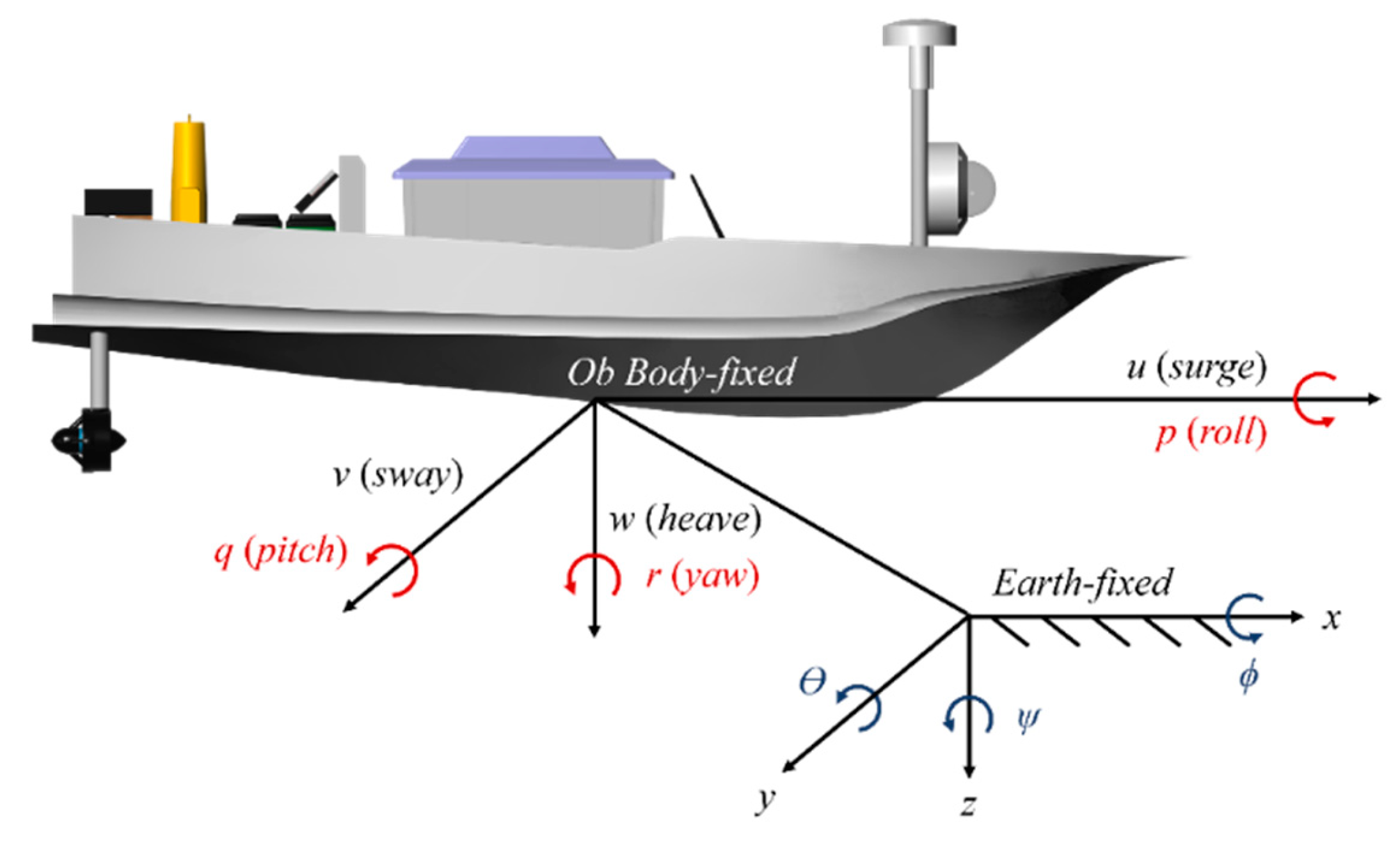
2.2. Governing Equations of USVs

As shown in Figure 2, a 3DOFs model (surge, sway, and yaw) was adopted for a controlled USV in this investigation.
Dynamics of the controlled USV in the body-fixed frame is formulated as [10]:
M B B ˙ + C B ( B ) B + D B ( B ) B = τ B + τ d B
where B = u v r T is the vector of velocities, u is the linear velocity in surge, v is the linear velocity in sway, and r is the angular velocity in yaw. Additionally, M B is the mass and inertia matrix, C B ( B ) is the Coriolis–centripetal matrix, D B ( B ) is the hydrodynamic damping matrix, τ B is the control input, and τ d B is the ocean environmental disturbances.
The transformation between the body-fixed frame to the earth frame of the controlled USV is:
η ˙ = J ( η ) B
where η = x y ψ T is the position of the controlled USV in the earth frame, and J ( η ) is the transformation matrix:
J ( η ) = cos ψ sin ψ 0 sin ψ cos ψ 0 0 0 1
The equations of motion of the controlled USV in the earth frame can be presented as:
M E ( η ) η ¨ + C E ( B , η ) η ˙ + D E ( η ) η ˙ = τ E + τ d E
where ME is the inertia mass in the earth frame, CE is the Coriolis–centripetal matrix in the earth frame, DE(η) is the damping matrix in the earth frame, τ d E is ocean environmental disturbance, and τ E is the control input.
The ocean environmental disturbance τ d E contains three sub-disturbances, which are the wave-induced disturbance τ w a v e , wind-induced disturbance τ w i n d , and ocean-current-induced disturbance τ c u r r e n t :
τ d E = τ w a v e + τ w i n d + τ c u r r e n t
The equations of motion of the controlled USV in the earth frame in Equation (4) will be used for the nonlinear fuzzy robust controller design, and the inertia mass M E ( η ) , Coriolis and centripetal matrix C E ( B , η ) , and damping matrix D E ( η ) can be expressed as nominal value terms M ¯ E ( η ) , C ¯ E ( B , η ) , D ¯ E ( η ) and modeling uncertainties Δ M E ( η ) , Δ C E ( B , η ) , Δ D E ( η ) :
M E ( η ) = M ¯ E ( η ) + Δ M E ( η ) C E ( B , η ) = C ¯ E ( B , η ) + Δ C E ( B , η ) D E ( η ) = D ¯ E ( η ) + Δ D E ( η )
Substituting (6) into (4), the dynamics equation of the USV can be reformulated as:
M ¯ E ( η ) η ¨ + C ¯ E ( B , η ) η ˙ + D ¯ E ( η ) η ˙ = τ E + Ξ
where
Ξ = τ d E Δ M E ( η ) η ¨ Δ C E ( B , η ) η ˙ Δ D E ( η ) η ˙
with Δ M E ( η ) η ¨ ε 1 , Δ C E ( B , η ) η ˙ ε 2 , and Δ D E ( η ) η ˙ ε 3 are bounded, and ε1, ε2, and ε3 are finite and bounded values.

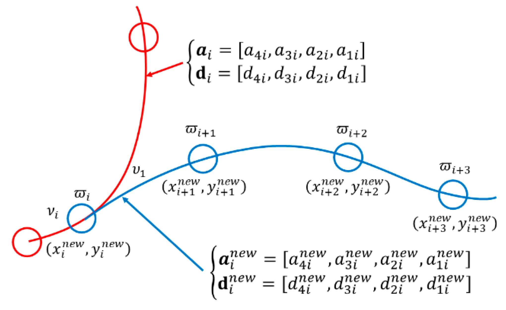
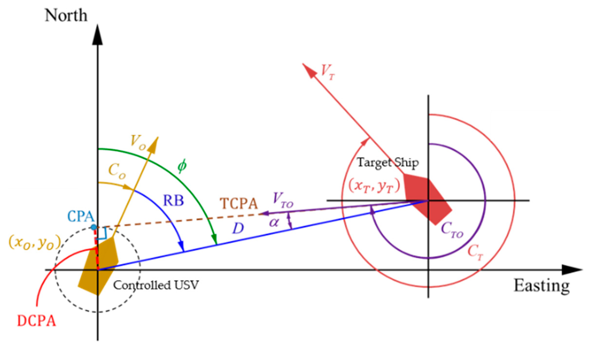
2.3. Generator of Collision-Free Trajectories

In the trajectory-tracking problem of USVs, a desired trajectory will be generated by interpolating a set of assigned waypoints if a collision-free condition is not demanded. However, the requirement of a collision-free condition must be met in practical sailing applications of USVs; hence, a real-time modified desired trajectory with no expected collisions should be arranged based on new sets of collision avoidance waypoints when a warning of a ship-to-ship collision occurs. In this investigation, a modification in generating sailing trajectories was adopted to create a collision avoidance trajectory for the controlled USV. A brief description of this modified trajectory generator is given below.
The conventional trajectory is made of multiple third-order polynomials, and two third-order polynomials can generate a continuous trajectory as follows:
x d ϖ = a 4 ϖ 3 + a 3 ϖ 2 + a 2 ϖ + a 1
y d ϖ = d 4 ϖ 3 + d 3 ϖ 2 + d 2 ϖ + d 1
where (xd (ϖ), yd (ϖ)) is the instantaneous position in the path, and a4, a3, a2, a1, d4, d3, d2, and d1 are identifiable coefficients. The related calculations of these coefficients are omitted in this investigation and can be found within [10]. In [10], the suggestion for arranging the new modified collision-free trajectory was to reassign a set of waypoints that can create a collision-free trajectory and satisfy the COLREGs. To ensure the modified trajectory connects to the original trajectory smoothly, as displayed in Figure 3, the position, velocity, and acceleration in the connected point (first red circle of the red trajectory) between these two trajectories must be the same. Based on this modified trajectory generator, a real-time, collision-free trajectory (the blue trajectory) that is made of a new set of coefficients (a4, a3, a2, a1, d4, d3, d2, and d1) can be obtained when the arbitrary collisions appear in the voyage of a controlled USV, and the state vector of this collision-free trajectory is defined as η d = x d y d ψ d T .

2.3.1. Integrated Fuzzy-Based Control System

The proposed control system used for the purpose of decision making and guidance for the controlled USV was developed by integrating “a fuzzy decision maker” and “a robust fuzzy control law”. In this proposed control system, the fuzzy decision maker, which is responsible for ship–ship collision evaluations and risk pre-warnings, consists of a fuzzy collision risk evaluator and a fuzzy collision avoidance acting timing indicator. As for the robust fuzzy control law, this part provides the precise trajectory tracking function to guide the USV to sail along the desired collision-free trajectory even under the effects of random ocean environmental disturbances and modeling uncertainties. Descriptions of this proposed control system will be given below.

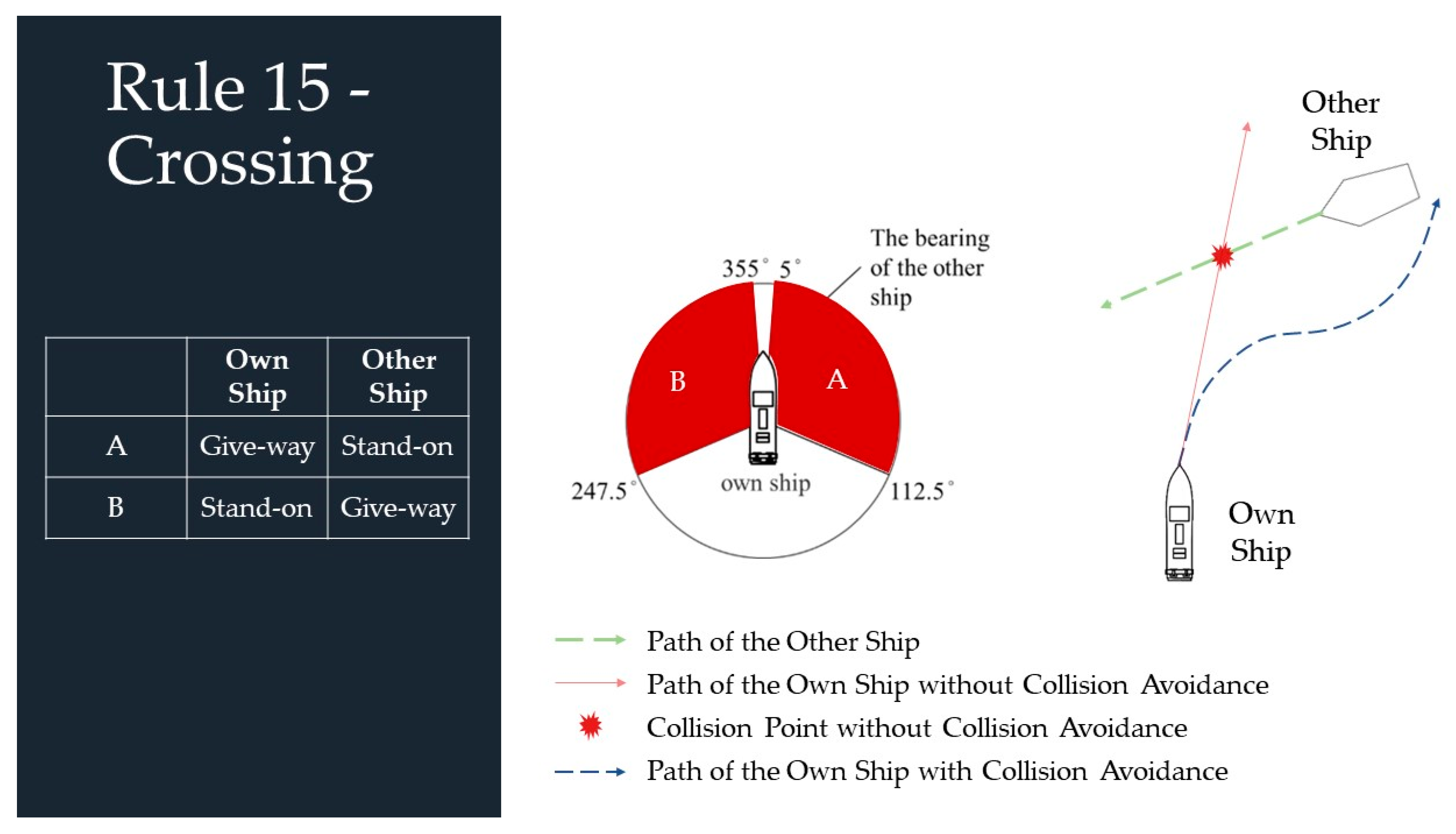
2.3.2. Fuzzy Decision Maker

In this investigation, a fuzzy decision maker that mainly comprises a fuzzy collision risk evaluator with an evaluated index µCRI ∈ [0, 1] and a fuzzy collision avoidance acting timing indicator with an evaluated index µCA ∈ [0, 1] were built to assess the collision risk and the degree of residual time for the controlled USV capable of taking evasive action with respect to the surrounding sailing USVs. To more safely guide the controlled USV with a definite collision-free condition under the effects of ocean environmental disturbances and modeling uncertainties in practice, conservative arrangements for three risk-evaluating parameters of these indicators: DCPA, TCPA, and total length D, which takes lengths of the controlled USV (LO) and target ship (LT) into account, were made as shown in Figure 4. The detailed design procedure of this fuzzy decision maker can be found in the published study [10]. In this investigation, sets of (µCRI ≥ 0.8, µCA ≥ 0.7) and (µCRI ≥ 0.3, µCA ≥ 0.7) will be utilized as thresholds for triggering the functions of reducing the speed of the controlled USV and generating a new collision-free trajectory by referring to [10].

2.4. Robust Fuzzy Control Law Design

Another significant part of this proposed control system is the “robust fuzzy control law”, which was designed with the aim of precisely guiding a controlled USV along a collision-free trajectory when random ships appear in the waterway. The design procedure of this robust fuzzy control law is derived below.
We defined the trajectory tracking error vector of the controlled USV with respect to arbitrary collision-free trajectories in the earth frame as follows:
e = η ˜ ˙ η ˜ = η ˙ η ˙ d η η d
where η d = x d y d ψ d T is the desired trajectory obtained by using the generator of collision-free trajectories.
Since η ¨ = M ¯ E ( η ) 1 C ¯ E ( B , η ) η ˙ + D ¯ E ( η ) η ˙ + M ¯ E ( η ) 1 τ E + M ¯ E ( η ) 1 Ξ and the generated collision-free trajectory is at least double-differentiable, namely, η d C 2 , the trajectory tracking error dynamics can be formulated as:
e ¨ = η ¨ d η ¨ = η ¨ d M ¯ E ( η ) 1 C ¯ E ( B , η ) η ˙ + D ¯ E ( η ) η ˙ + M ¯ E ( η ) 1 τ E + M ¯ E ( η ) 1 Ξ
Selecting a candidate control law τ E as follows:
τ E = M ¯ E ( η ) Γ 2 e + C ¯ E ( B , η ) η ˙ + D ¯ E ( η ) η ˙ η ¨ d + Ξ ^ + R u
where R u is the robust compensator that will be designed later developed for eliminating the residual overall disturbance, and Ξ ^ is a fuzzy approximator of the overall disturbance. The disclosure results reveal that a well-developed fuzzy system can be utilized to be a universal approximator for approaching any nonlinear systems as precisely as possible in [11,12,13]. Based on the concept of [11,12,13], the proposed fuzzy approximator Ξ ^ can be expressed as a regression form as below:
Ξ ^ = Θ w T * λ w
where Θ w = θ w 1 θ w 2 θ w M T is the adjustable parameter vector, and λ w = λ w 1 λ w 2 λ w M T is the fuzzy basis function, respectively. λ w i is defined as:
λ w i ( x ) = Π i = 1 n μ λ w i l ( x i ) l = 1 M Π i = 1 n μ λ w i l ( x i )
where M is the rule number.
The optimal fuzzy approximation error can be further presented as:
Δ Ξ = Ξ Ξ ^ * = Ξ Θ w T * λ w
where Θ w * = arg min Θ w Ξ Θ w T λ w .
Remark 1.
Theoretically speaking, by increasing the rule number M, the approximation error can be mitigated as far as possible. However, a trade-off between the accuracy of the fuzzy approximator and the computational effort should be made in practice.
Based on Equations (1), (13), (14), and (16), a matrix–vector form of the trajectory tracking error dynamics can be obtained:
e ¨ + Γ 1 e ˙ + Γ 2 e = Θ ˜ w T λ w + R u + M ¯ E ( η ) 1 Δ Ξ
where Θ ˜ w = Θ w * Θ w .
The trajectory tracking error dynamics in Equation (17) can be further expressed in an augmented form as
E ˙ = A E + B R u + B Θ ˜ w T λ w + B d = 0 1 Γ 1 Γ 2 E + 0 1 R u + 0 1 Θ ˜ w T λ w + 0 1 d
where
E = e e ˙ T ,
d = M ¯ E ( η ) 1 Δ Ξ ,
Γ 1 = α 1 0 0 0 α 2 0 0 0 α 3 ,
and
Γ 2 = α 4 0 0 0 α 5 0 0 0 α 6
From Equation (18), the design target for the controlled USV’s collision-free trajectory tracking problem can be described as a robust performance as follows [14,15,16]:
min R u ( t ) L 2 [ 0 , t f ] min d ( t ) L 2 [ 0 , t f ] Q 1 2 E ( t ) + O 1 2 R u ( t ) L 2 [ 0 , t f ] d ( t ) L 2 [ 0 , t f ] ρ
where ρ is a designable attenuation level, and Q and O > 0 are the weighting matrices as well.
The results disclosed in Theorem 1 below indicate the fact that the design objective in Equation (19) can be achieved with the derived robust compensator R u and the adaptive law for optimally searching the parameter vector Θ w of the fuzzy approximator Ξ ^ .
Theorem 1.
The precise trajectory tracking problem of unmanned surface vessels can be tackled well with the robust fuzzy control law τ E  which integrates a robust compensator  R u  and an adaptive law  Θ ˙ w  expressed below.
τ E = M ¯ E ( η ) Γ 2 e + C ¯ E ( B , η ) η ˙ + D ¯ E ( η ) η ˙ η ¨ d + Ξ ^ + R u
R u ( t ) = R 1 B T P E ( t )
and P = P T > 0  is one of the solutions to the following equation:
A P + P A T + P B 1 ρ 2 I O 1 B T P + Q = 0
The adaptive law for optimally searching the parameter vector  Θ w  is derived as:
Θ ˙ w = γ f λ W T B T P E ( t )
where  γ f  is the designable learning rate.
Proof of Theorem 1 can be obtained in Appendix A.

2.5. Summary of the Proposed Fuzzy-Based Control System

STEP 1.
Set up key parameters DCPA, TCPA, and total length D of the fuzzy decision maker to generate the fuzzy collision risk index µCRI and the fuzzy collision avoidance acting timing index µCA.
STEP 2.
Specify A in Equation (18) with design eigenvalues αI > 0, for I = 1, …, 6.
STEP 3.
Select the weight matrices Q > 0, the desired attenuation level ρ, and the weighting factor O such that ρ2I-O must be a positive definite matrix.
STEP 4.
Solve Equation (22) to obtain P.
STEP 5.
Construct the fuzzy approximator Ξ ^ ( t ) = Θ w T ( t ) λ w and Θ ˙ w ( t ) = γ f λ W T B T P E ( t ) for mimicking the overall disturbance Ξ ( t ) .
STEP 6.
Construct the robust compensator R u ( t ) = R 1 B T P E ( t ) and the nonlinear fuzzy robust control law τ E = M ¯ E ( η ) Γ 2 e + C ¯ E ( B , η ) η ˙ + D ¯ E ( η ) η ˙ η ¨ d + Ξ ^ + R u in Equation (13) for the collision-free and precise trajectory tracking problem of the controlled USV.

3. Simulation Results

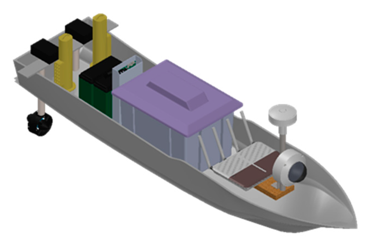
3.1. System and Control Parameters of the Controlled USV

The controlled USV utilized for simulation in this investigation had a length of 1.72 m, as shown in Figure 5. The related hydrodynamic parameters ( X u ˙ , Y v ˙ , Y r ˙ , N r ˙ , X u , Y v , Y r , N v , and N r ) of this USV were measured by using a towing tank experiment, and the detailed parameters of this USV are stated in Table 1.

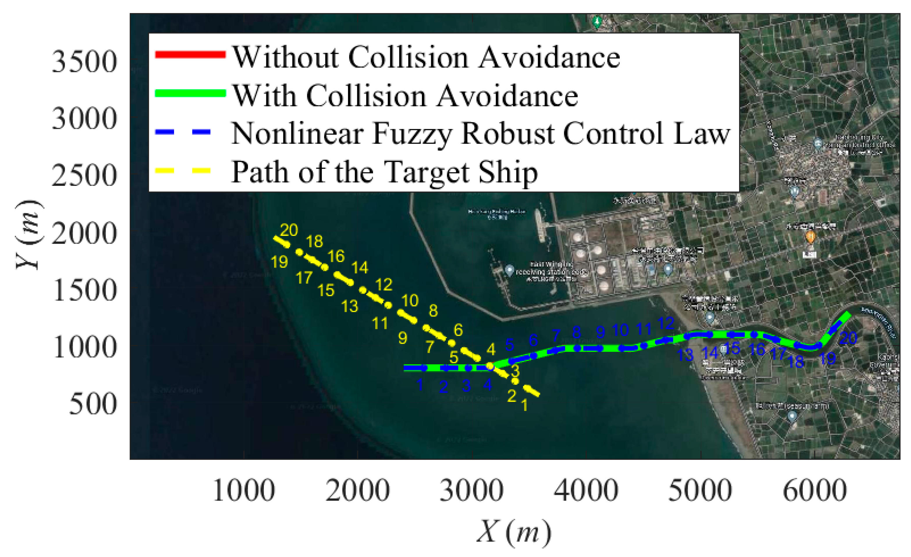
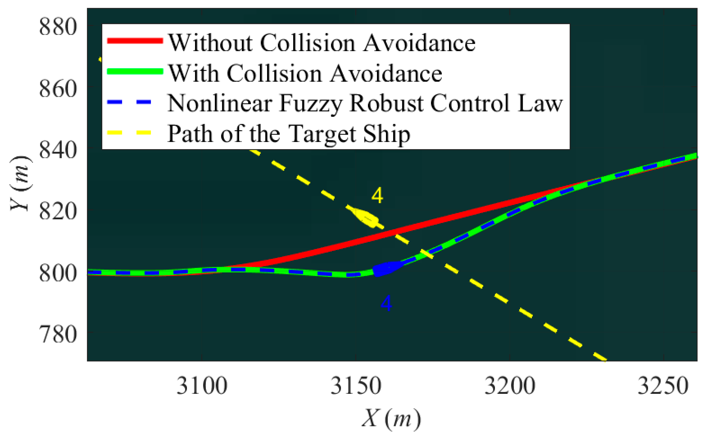
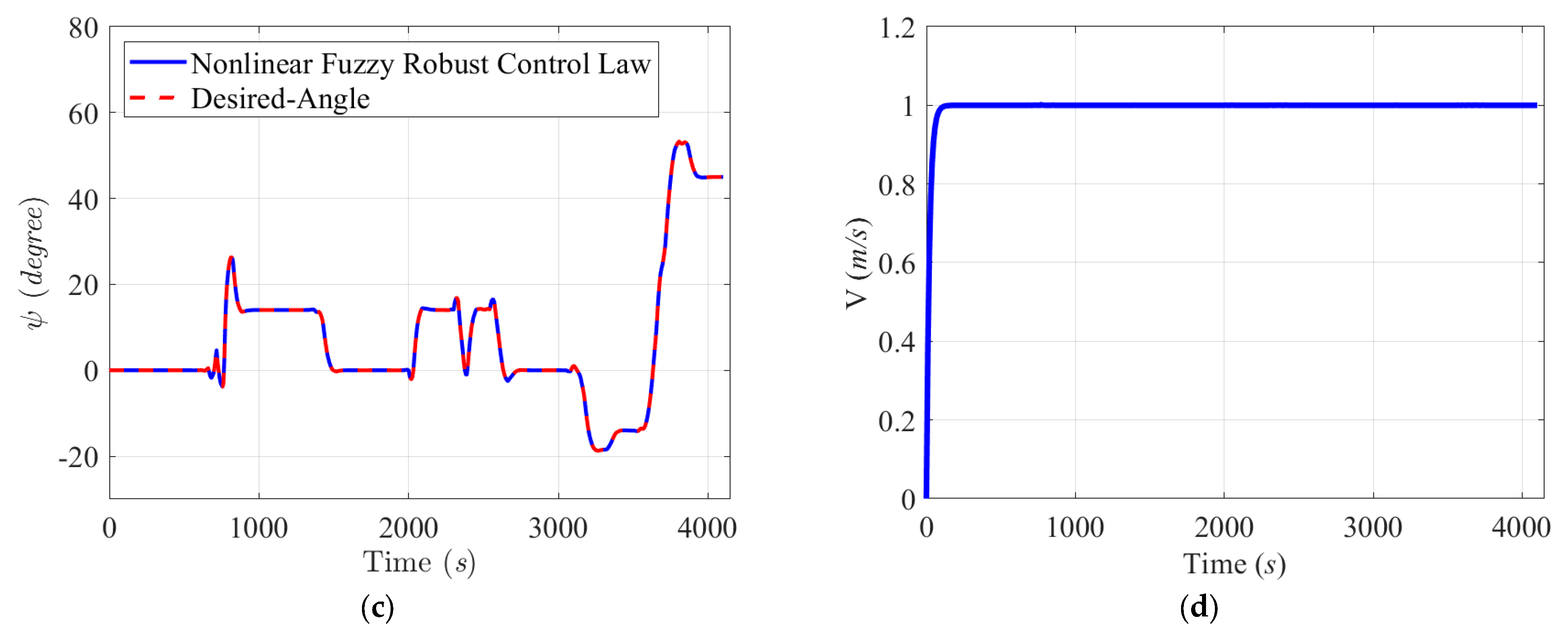
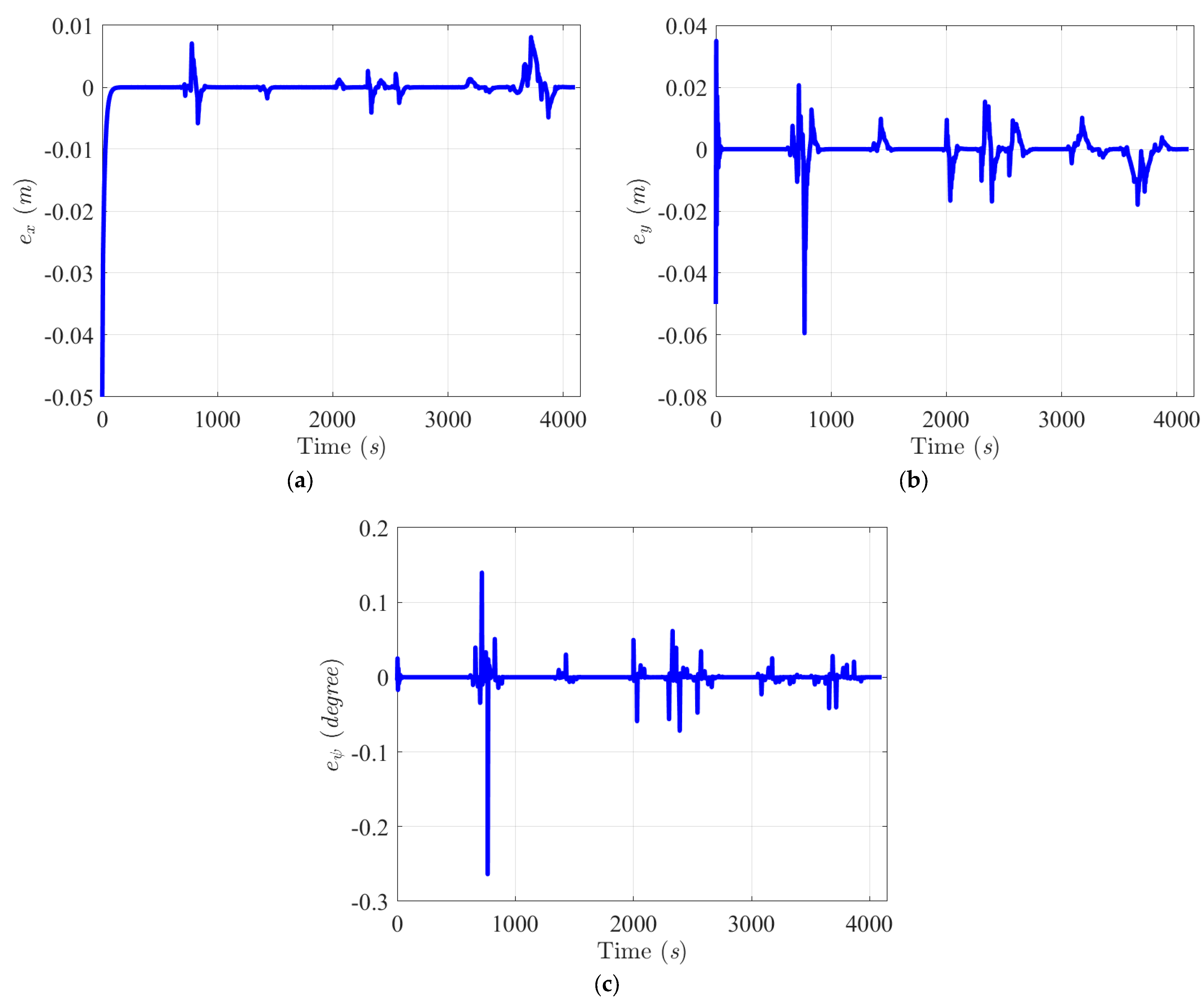
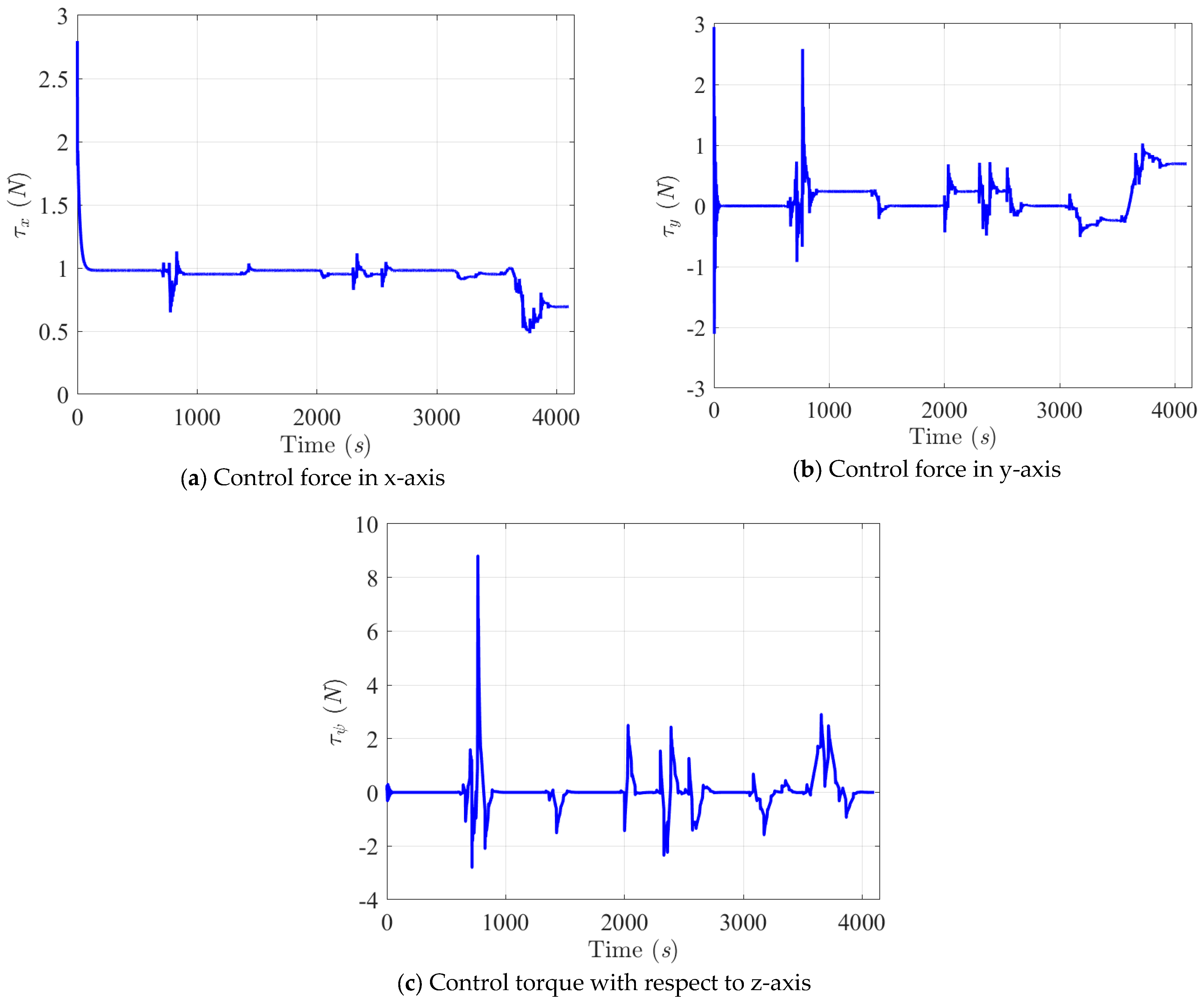
3.2. Collision Avoidance Simulation Results of the Proposed Control System

One collision avoidance scenario was simulated in Yongxin Fish Harbor of Kaohsiung City, Taiwan, for the validation of the collision avoidance performance of this proposed control system under the influences of ocean disturbances and modeling uncertainties. The modeling uncertainties of the controlled USV were considered 10% of the nominal values of the system parameters in Table 1, and the ocean environmental disturbance τ d E was created by referring to the published paper [17]. To verify the collision avoidance performance of the proposed control system, a crossing situation was arranged in this scenario. As displayed in Figure 6 and according to rule 15 of the COLREGs, the controlled USV was a give-way ship, and the target ship was a stand-on ship for this crossing situation. Following rule 15, it was suggested that the stand-on ship sail straight forward, and the give-way ship perform a give-way action along a collision-free trajectory.
In this scenario, the corresponding settings of the controlled USV (own ship) and the target ship are listed in Table 2 and Table 3.
Figure 7 shows the collision avoidance simulation result for two sailing ships. In this scenario, a target ship sails straight from the coast (southeast) to the ocean (northwest), and the controlled USV sails from the ocean (west) to the internal river. From Figure 8, it is obvious that these two ships have a very high probability of colliding at point 4; hence, the controlled USV should take evasive action according to rule 15 of the COLREGs because it is its own ship.
The enlarged figure around point 4 of Figure 8 details the relative actions taken by the target ship and the controlled USV.
This figure shows that a collision will occur at point 4 if the controlled USV sails along the original predefined trajectory (red line). To avoid this unexpected collision situation, a decision was made by the proposed control system: “the proposed control system rearranges a collision-free trajectory (blue line) once a ship-ship collision is estimated by the proposed fuzzy collision risk evaluator, and the fuzzy robust control law then robustly guide the USV to precisely follow the collision-free trajectory under influences of modelling uncertainties and ocean environmental disturbances”. Figure 9a–c and Figure 10a–c show that the proposed fuzzy robust control law has very promising robustness in terms of modeling uncertainties and ocean disturbances and can guide the USV to precisely follow the collision-free trajectory not only in position but also in attitude. Figure 9d indicates the sailing velocity, and it was well-maintained at 1 m/s by the trajectory generator.
The control forces and torque of this scenario are illustrated in Figure 11. From these control command histories, bigger control forces and torque can be seen in the time interval [600 s, 800 s]. This is because collision risks were detected by the fuzzy decision maker at about 600 s, and a right-hand side turn was made by the proposed fuzzy robust control law for the controlled USV to avoid a collision with the target ship. The collision avoidance response of this proposed control system certainly follows rule 15 of the COLREGs: “In crossing situation, the own ship must take a give-way action”. From the simulation results of this scenario, we can conclude that this proposed control system delivers very promising collision avoidance performance for USVs carrying out tasks in an ocean environment full of various sailing surface vessels and random disturbances, such as waves, winds, and currents.
From the trajectory tracking error histories in the X-axis (a) and Y-axis (b) and the tracking error history of the heading angle ψ, we can determine that the mean square errors in positions ( M S E e P ) and in the heading angle ( M S E e ψ ) under the influences of 10% modeling uncertainties and random environmental disturbances are M S E e P 0.04 m and M S E e ψ 0.1 ° , respectively.

4. Conclusions

An integrated fuzzy-based control system with collision-free trajectory and precise trajectory tracking properties was tested in the real-time collision avoidance sailing operation of a controlled USV in this investigation. The trajectory tracking problem of intelligent USVs with a collision-free property comprises developments in data sensing, decision making, collision-free trajectory generation, and robust control; hence, the complexity of this problem is higher than that of the conventional control design of USVs. This proposed fuzzy-based control system consists of four major subsystems: a fuzzy collision risk evaluator, a fuzzy collision avoidance acting timing indicator, a collision-free trajectory generator, and a nonlinear adaptive fuzzy robust control law. The first two functions provide the controlled USVs with a decision-making function to determine when to take evasive action. Based on the pre-alarm of the first two functions, one new collision-free trajectory can be generated by using the cubic spline method in real-time. Finally, the nonlinear adaptive fuzzy control law plays the role of precisely guiding the USV to sail along the new collision-free trajectory. To realistically examine the performance of this proposed method, a crossing situation scenario that frequently occurs in the encounter situation of ships was simulated in the area of the Yongxin Fish Harbor of Kaohsiung City, Taiwan. From the simulation results, transparently, this proposed control system could make the correct evasion decisions to guide the USV to sail along the rearranged collision-free trajectory precisely and robustly by following the COLREG rules under the effects of modeling uncertainties and ocean environmental disturbances. The mean-square errors could be controlled to levels of M S E e P 0.04 m for the position and M S E e ψ 0.1 ° for the heading angle, respectively. Although this proposed control system of intelligent USVs integrates four subsystems and can deliver satisfactory collision-free and precise trajectory tracking performance, merging actuator models, such as rudders and thrusters, etc., are inevitably required for real applications. How to analytically convert actuator models’ inputs into the desired control law (τx, τy, and τψ) will be the next research challenge due to the high nonlinearity of the input and output relationship of actuator models.

Author Contributions

Conceptualization, Y.-Y.C.; methodology, Y.-Y.C.; software, M.-Z.E.-T.; validation, Y.-Y.C. and M.-Z.E.-T.; formal analysis, M.-Z.E.-T.; investigation, Y.-Y.C.; re-sources, Y.-Y.C.; data curation, M.-Z.E.-T.; writing—original draft preparation, Y.-Y.C.; writing—review and editing, M.-Z.E.-T.; visualization, M.-Z.E.-T.; supervision, Y.-Y.C.; project administration, Y.-Y.C.; funding acquisition, Y.-Y.C. All authors have read and agreed to the published version of the manuscript.

Funding

This research was funded by the MOST (Ministry of Science and Technology of Taiwan, project number is NSTC112-2221-E-006-152-.

Data Availability Statement

Not applicable.

Conflicts of Interest

The authors declare no conflict of interest.

Appendix A

We defined the robust performance index J for the controlled USV’s collision-free trajectory tracking problem as:
J E ( t ) , R u ( t ) , d ( t ) = 0 t f E ( t ) T Q E ( t ) + R u ( t ) T ( t ) O R u ( t ) ρ 2 d ( t ) T d ( t ) d t
Equation (A1) can be further reformulated as below:
J E ( t ) , R u ( t ) , d ( t ) = E ( 0 ) T P E ( 0 ) E ( t f ) T P E ( t f ) + 1 γ f Θ ˜ w ( 0 ) T Θ ˜ w ( 0 ) 1 γ f Θ ˜ w ( t f ) T Θ ˜ w ( t f ) + 0 t f E ( t ) T ( A P + P A T + P B 1 ρ 2 I O 1 B T P + Q ) E ( t ) + R u ( t ) T O R u ( t ) + R u ( t ) T B T P E ( t ) + E ( t ) T P B R u ( t ) + E ( t ) T P B λ w + 1 γ f Θ ˜ ˙ w ( t ) T Θ ˜ w ( t ) + Θ ˜ w ( t ) T λ w T B T P E ( t ) + 1 γ f Θ ˜ ˙ w ( t ) + d ( t ) T B T P E ( t ) + E ( t ) T P B d ( t ) + d ( t ) T d ( t ) d t
Equation (A2) can be expressed as the following result based on the selections of Θ ˜ ˙ w ( t ) = γ f λ w T B T P E ( t ) and A T P + P A + Q + P B 1 ρ 2 I O 1 B T P = 0 :
J E ( t ) , R u ( t ) , d ( t ) = E ( 0 ) T P E ( 0 ) E ( t f ) T P E ( t f ) + 1 γ f Θ ˜ w ( 0 ) T Θ ˜ w ( 0 ) 1 γ f Θ ˜ w ( t f ) T Θ ˜ w ( t f ) + 0 t f R u ( t ) T O R u ( t ) + R u ( t ) T B T P E ( t ) + E ( t ) T P B R u ( t ) + d ( t ) T B T P E ( t ) + E ( t ) T P B d ( t ) + d ( t ) T d ( t ) d t
By completing the square, Equation (A3) can be described as a more concise form:
J E ( t ) , R u ( t ) , d ( t ) = E ( 0 ) T P E ( 0 ) E ( t f ) T P E ( t f ) + 1 γ f Θ ˜ w ( 0 ) T Θ ˜ w ( 0 ) 1 γ f Θ ˜ w ( t f ) T Θ ˜ w ( t f ) + 0 t f O R u ( t ) + B T P E ( t ) T O 1 O R u ( t ) + B T P E ( t ) + d ( t ) 1 ρ B T P E ( t ) T d ( t ) 1 ρ B T P E ( t ) + d ( t ) T d ( t ) d t
For the purpose of minimizing Equation (A4), we selected the robust compensator R u ( t ) and the worst-case modeling uncertainty d ( t ) as the following:
R u ( t ) = R 1 B T P E ( t )
d ( t ) = 1 ρ B T P E ( t )
After choosing R u ( t ) and d ( t ) as Equations (A5) and (A6), the minimum value of the robust performance index J can be obtained as follows:
J E ( t ) , R u ( t ) , d ( t ) = E ( 0 ) T P E ( 0 ) + 1 γ f Θ ˜ w ( 0 ) T Θ ˜ w ( 0 )
If E ( 0 ) = Θ ˜ w ( 0 ) = 0 , Equations (A7) and (19) are equivalent. Then, Theorem 1 is proven.

References

  1. Autonomous Shipping Is Making Waves. International Telecommunication Union. Available online: https://www.itu.int/hub/2020/04/autonomous-shipping-is-making-waves/ (accessed on 14 July 2020).
  2. Autonomous Ships Market Expected to Reach US$ 235.73 Bn by 2028. Acute Market Reports. Available online: https://www.acutemarketreports.com/press/global-autonomous-ships-market (accessed on 15 March 2017).
  3. Hyundai Heavy Industries (HHI) Group. HD Hyundai’s Avikus Successfully Conducts the World’s First Transoceanic Voyage of a Large Merchant Ship Relying on Autonomous Navigation Technologies; HD Hyundai: Seoul, Republic of Korea, 2022. [Google Scholar]
  4. Goerlandt, F.; Montewka, J.; Kuzmin, V.; Kujala, P. A Risk-Informed Ship Collision Alert System: Framework and Application. Saf. Sci. 2015, 77, 182–204. [Google Scholar] [CrossRef]
  5. Beser, F.; Yildirim, T. COLREGS Based Path Planning and Bearing only Obstacle Avoidance for Autonomous Unmanned Surface Vehicles. Procedia Comput. Sci. 2018, 131, 633–640. [Google Scholar] [CrossRef]
  6. Sedova, N.A.; Sedov, V.A.; Bazhenov, R.I.; Alutina, E.F.; Arkhipova, Z.V.; Mendel, V.V. Intelligent Collision Danger Assessment of Autonomous Unmanned Sea-Going Vessels. In Proceedings of the 2022 International Conference on Quality Management, Transport and Information Security, Information Technologies (IT&QM&IS), Saint Petersburg, Russia, 26–30 September 2022; pp. 197–201. [Google Scholar]
  7. Chiang, H.T.L.; Tapia, L. COLREG-RRT: An RRT-Based COLREGS-Compliant Motion Planner for Surface Vehicle Navigation. IEEE Robot. Autom. Lett. 2018, 3, 2024–2031. [Google Scholar] [CrossRef]
  8. Hu, L.; Naeem, W.; Rajabally, E.; Watson, G.; Mills, T.; Bhuiyan, Z.; Raeburn, C.; Salter, I.; Pekcan, C. A Multiobjective Optimization Approach for COLREGs-Compliant Path Planning of Autonomous Surface Vehicles Verified on Networked Bridge Simulators. IEEE Trans. Intell. Transp. Syst. 2020, 21, 1167–1179. [Google Scholar] [CrossRef]
  9. Zhao, L.; Roh, M.-I. COLREGs-Compliant Multiship Collision Avoidance Based on Deep Reinforcement Learning. Ocean. Eng. 2019, 191, 106436. [Google Scholar] [CrossRef]
  10. Chen, Y.-Y.; Ellis-Tiew, M.-Z.; Chen, W.-C.; Wang, C.-Z. Fuzzy Risk Evaluation and Collision Avoidance Control of Unmanned Surface Vessels. Appl. Sci. 2021, 11, 6338. [Google Scholar] [CrossRef]
  11. Llama, M.; Flores, A.; Garcia-Hernandez, R.; Santibañez, V. Heuristic Global Optimization of an Adaptive Fuzzy Controller for the Inverted Pendulum System: Experimental Comparison. Appl. Sci. 2020, 10, 6158. [Google Scholar] [CrossRef]
  12. Ruiyun, Q.; Gang, T.; Bin, J. Fuzzy System Identification and Adaptive Control; Springer International Publishing: Cham Switzerland, 2019. [Google Scholar] [CrossRef]
  13. Chen, Y.-Y.; Chang, Y.-T.; Chen, B. Fuzzy Solutions to Partial Differential Equations: Adaptive Approach. IEEE Trans. Fuzzy Syst. 2009, 17, 116–127. [Google Scholar] [CrossRef]
  14. Wang, A.; Liu, L.; Qiu, J.; Feng, G. Event-Triggered Robust Adaptive Fuzzy Control for a Class of Nonlinear Systems. IEEE Trans. Fuzzy Syst. 2019, 27, 1648–1658. [Google Scholar] [CrossRef]
  15. Wu, J.L. Robust H∞ Control for polytopic Nonlinear Control Systems. IEEE Trans. Autom. Control 2013, 58, 2957–2962. [Google Scholar] [CrossRef]
  16. Chen, Y.-Y.; Lin, L.-K.; Hung, M.-H. Controllable Micromseter Positioning Design of Piezoelectric Actuators Using a Robust Fuzzy Eliminator. Microelectron. Reliab. 2019, 103, 113497. [Google Scholar] [CrossRef]
  17. Fossen, T. Handbook of Marine Craft Hydrodynamics and Motion Control; John Wiley & Sons: Hoboken, NJ, USA, 2021. [Google Scholar]
Figure 1. Details of the proposed collision avoidance control system for USVs.
Mathematics 11 03632 g001
Figure 2. Motions of USV in body-fixed and earth frames.
Mathematics 11 03632 g002
Figure 3. Schematic diagram of generating a collision-free trajectory.
Mathematics 11 03632 g003
Figure 4. DCPA, TCPA, and total length D between two encountered USVs.
Mathematics 11 03632 g004
Figure 5. The controlled USV of this investigation.
Mathematics 11 03632 g005
Figure 6. Collision avoidance strategy for a two-ship crossing situation based on rule 15 of the COLREGs.
Mathematics 11 03632 g006
Figure 7. Collision avoidance simulation in Yongxin Fishing Harbor: the yellow line is the trajectory of the target ship, the blue line is the trajectory of the controlled USV, and the green line is the desired collision-free trajectory.
Mathematics 11 03632 g007
Figure 8. Magnifying the collision part of Figure 7.
Mathematics 11 03632 g008
Figure 9. Collision-free trajectory tracking histories in X-axis (a) and Y-axis (b), tracking history of the heading angle ψ (c), and (d) the sailing velocity V with respect to Scenario 1.
Mathematics 11 03632 g009aMathematics 11 03632 g009b
Figure 10. Collision-free trajectory tracking error histories in X-axis (a) and Y-axis (b), and tracking error history of heading angle ψ (c) with respect to Scenario 1.
Mathematics 11 03632 g010
Figure 11. Histories of the control commands, including the forces τx, τy, and the torque τψ with respect to Scenario 1.
Mathematics 11 03632 g011
Table 1. Detail system parameters of the controlled USV.
Length L1.72 m
Width B0.4 m
Draft T0.3 m
Mass m41 kg
Iz6.522 kg∙m
xg0 m
X u ˙ −1.291 kg
Y v ˙ −40.326 kg
Y r ˙ −39.04525 N∙s2/m2
N r ˙ 200.79808 N∙m∙s
X u −0.98 N∙s2/m2
Y v −38.808 N∙s2/m2
Y r −16.43778 N∙s
N v −14.340 N∙s2/m2
N r −236.5 N∙m∙s
Table 2. Setting of the controlled USV for the simulation.
Starting Point(2400 m, 800 m)
Goal Point(6300 m, 1280 m)
Desired Velocity1 m/s
Initial Condition of the Controlled USV η = 2399.95   m 799.95   m 0
Table 3. Setting of target ship for the simulation.
Starting Point(3586 m, 559 m)
Goal Point(0, 2700 m)
Desired Velocity0.663 m/s
Disclaimer/Publisher’s Note: The statements, opinions and data contained in all publications are solely those of the individual author(s) and contributor(s) and not of MDPI and/or the editor(s). MDPI and/or the editor(s) disclaim responsibility for any injury to people or property resulting from any ideas, methods, instructions or products referred to in the content.

