Article

Numerical Simulation of Hole Cleaning of a Horizontal Wellbore Model with Breakout Enlargement Section

1
Sanya Offshore Oil & Gas Research Institute, Northeast Petroleum University, Sanya 572025, China
2
College of Petroleum Engineering, Northeast Petroleum University, Daqing 163318, China
3
Department of Engineering and Applied Science, Memorial University of Newfoundland, St. John’s, NF A1B 3X5, Canada
*
Author to whom correspondence should be addressed.
Mathematics 2023, 11(14), 3070; https://doi.org/10.3390/math11143070
Submission received: 19 June 2023 / Revised: 5 July 2023 / Accepted: 8 July 2023 / Published: 12 July 2023

Abstract

:
Horizontal wells are more likely than vertical wells to have enlarged wellbore sections due to borehole instability. However, there is scarce research on borehole cleaning of horizontal wells with enlarged wellbore sections. In this paper, we establish a horizontal wellbore model with a breakout enlargement section using field borehole diameter data. We used the three-dimensional computational fluid dynamics (CFD) method and the Realizable k-ε turbulence model with the Euler–Euler approach to simulate the effects of the drilling fluid circulation return speed and the spinning speed of the drill pipe on the cutting movement of conventional horizontal wells and horizontal wells with a breakout enlargement section. The simulation results demonstrate that increasing the drilling fluid circulation return speed and the spinning speed of the drill pipe does not significantly improve the hole cleaning impact for horizontal wells with a breakout enlargement section. We analyzed the effects of the enlargement ratio, ellipticity, and principal axis orientation on the borehole cleaning effect of horizontal wells with a breakout enlargement section. The results show that the cleaning impact is better when the enlargement ratio is lower; moreover, the ellipticity is larger and the principal axis orientation is perpendicular to the gravity direction. This paper fills a gap in the existing theory of hole cleaning in horizontal wells and provides a theoretical basis for improving the hole cleaning effect in actual drilling processes.

1. Introduction

According to the International Energy Agency’s forecast, global energy demand is expected to grow by 19% by 2040. In the preceding years, conventional petroleum and natural gas fields have not been able to meet the world’s demand for petroleum and natural gas. Increasing the development of unconventional petroleum and natural gas can effectively ramp up the extraction of petroleum and natural gas to ease the energy crisis [1]. The horizontal wellbore approach is often employed in unconventional petroleum and natural gas development [2,3,4,5]. The contact area between the wellbore and the petroleum and natural gas reservoir is larger for horizontal wells than for vertical wells, which can effectively increase the recovery rate for petroleum and natural gas production [6,7,8].
Horizontal wells are easily affected by the gravitational effect of cutting and casing eccentricity, forming cuttings beds and causing high friction and torque of the drill pipe, with serious effects on hole cleaning efficiency [9,10,11,12]. When the horizontal wellbore is not sufficiently cleaned, the annular pressure increases significantly, which can easily lead to formation leaks, blowouts, and other accidents. In addition, cuttings beds further increase the friction and torque of the drill pipe, leading to frequent incidents of stuck or broken drills and other accidents [13,14,15,16] as well as increasing the difficulty of subsequent logging, cementing completion, and other operations, affecting the engineering quality [17,18,19,20]. A review of borehole cleaning in horizontal and high-angle wells by Mahmoud et al. [21] suggested that cuttings transport is greatly influenced by the spinning speed of the drill pipe, the flow rate, and the rheological characteristics of the mud. Ma et al. [22] analyzed the influence of the annular velocity, compactness of the drilling fluid, spinning speed of the drill pipe, and eccentricity on hole cleaning through high-angle section and horizontal section cuttings transport experiments. Bilgesu et al. [23] found that increasing the drilling fluid circulation return speed and the drill pipe rotation speed can effectively improve the hole cleaning effect, and that for smaller cuttings particle sizes the effect of this improvement is more obvious. Ozbayoglu et al. [24] found through experiments that when the speed of the drill pipe rotation went up to 40 r/min from 0 r/min the cuttings bed area decreased significantly, while when the rotation speed increased to 120 r/min the cuttings bed area decreased slightly; thus, there is an optimal drill pipe rotation speed for the hole cleaning problem. The existing research believes that increasing the drilling fluid circulation return speed can most effectively improve the horizontal hole cleaning effect.
Compared with vertical wells, horizontal wells are more susceptible to the influence of bedding planes, fractures, and anisotropy, resulting in unstable rock strength. Moreover, the complexity of horizontal wellbore geometry and trajectory makes horizontal wells more susceptible to the influence of ground stress direction and magnitude, resulting in wellbore instability problems such as borehole collapse and borehole enlargement [25,26]. Liu [27] divided elliptical borehole enlargement into three types: keyway, erosion, and breakouts. McLellan et al. [28] reconstructed the shape of an enlarged borehole at 2391 m in a well in western Canada using borehole imaging logging and biaxial logging tools. The borehole was an elliptical enlargement with a long axis enlargement rate of 60%. Pierdominici et al. [29] identified 371 borehole breakout phenomena using acoustic imaging. Figure 1 shows a three-dimensional view of a borehole based on acoustic borehole images.
Ju et al. [30] compared the cuttings clearance capability of elliptic drill pipes with that of conventional circular drill pipes. Increasing the rotation speed can effectively improve the cuttings clearance capability of elliptic drill pipes. The larger the ellipticity of elliptical drill pipes is, the more obvious the improvement effect of hole cleaning is. Unlike circular drill pipes, the larger the eccentricity is, the easier it is for cuttings to be transported by elliptical drill pipes. Qu et al. [31] found through numerical simulation that four-leaf drill pipes are conducive to generating swirls in drilling fluid, improving hole cleaning efficiency. Chen et al. [32] used a transient solid transport model to evaluate wave-shaped borehole cleaning risk and wave trajectory pressure. He concluded that upward inclined wells have lower cuttings concentration than downward inclined wells, meaning that there is an optimal accumulation rate for hole cleaning efficiency. Compared with conventional circular annulus, the cuttings transport law in irregular borehole shape section is different and the mechanism is unclear [33,34].
This paper uses the CFD numerical simulation method to analyze cuttings transport behavior in breakouts enlargement annulus using the FVM solver. First, we compare the impact of the drilling fluid circulation return speed and drill pipe rotation speed on the improvement effect of hole cleaning in conventional and enlarged boreholes. On this basis, we analyze the influence of the enlargement rate, ellipticity, and major axis orientation angle on cuttings transport in enlarged boreholes. Our research results fill a gap in the existing horizontal well cuttings transport theory, and provide a theoretical basis for improving the hole cleaning effect in the actual drilling process. This means that the present research can help to optimize the design and operation of horizontal wells, reduce the risk of stuck pipes and hole collapse, and enhance drilling efficiency and safety. This research contributes to the development of new methods and technologies for cuttings transport and hole cleaning in horizontal wells, such as applying vibration or rotation tools, installing cuttings bed breakers, etc. The present research can be extended to other types of complex wells, such as multilateral wells and coiled tubing drilling wells, where cuttings transport and hole cleaning are challenging issues.

2. Methodology

This study uses the Eulerian–Eulerian multiphase flow model to study solid–liquid two-phase flows where both phases are treated as continuous media. This method is more efficient and acceptable than the Eulerian–Lagrangian approach. For the purpose of considering the problem of turbulence, this paper uses the Realizable k-ε instability representation.

2.1. Mathematical Models

Regarding the particles and fluid within the circle, the continuity equation and momentum equation of both are established in [35,36].
Continuity equation:
α 1 ρ 1 t + α 1 ρ 1 u 1 = 0
α s ρ s t + α s ρ s u s = 0
Momentum equation:
α 1 ρ 1 u 1 t + α 1 ρ 1 u 1 u 1 = α 1 p + α 1 τ + α 1 ρ 1 g β v 1 v s
α s ρ s u s t + α s ρ s u s u s = α s p p s + α s τ + α s ρ s g + β v 1 v s
where the subscripts 1 and s respectively represent the drilling fluid and cuttings; α represents volume fraction; ρ represents density, g/cm3; u represents velocity vector; p represents pressure, Pa; ps represents solid phase pressure, Pa; τ represents stress tensor, N/m2; g represents gravitational acceleration, m/s2; and β represents the interphase momentum transfer coefficient.
The expression of the solid phase pressure ps is as follows [37]:
p s = α s ρ s Θ s + 2 ρ s 1 + e s s α s 2 g 0 , s s Θ s
where ess represents the restitution coefficient of particle collision; Θs represents the granular temperature, m2/s2; and g0,ss represents the radial distribution function, for which the expression is as follows:
g 0 , s s = 1 α s α s , max 1 3 1
The expression of the granular temperature Θs is as follows:
Θ s = 1 3 u s , i u s , i
In the two-fluid model, the solid-phase viscosity consists of the collision viscosity, kinetic viscosity, and friction viscosity [38,39]:
μ s = μ s , col + μ s , kin + μ s , fr
The expressions of the collision viscosity μs,cd, kinetic viscosity μs,kin, and friction viscosity μs,fr are as follows:
μ s , col = 4 5 α s ρ s d s g 0 , s s 1 + e s s Θ s π 1 / 2 α s
μ s , kin = 10 ρ s d s Θ s π 96 α s 1 + e s s g 0 , s s 1 + 4 5 g 0 , s s α s 1 + e s s 2 α s
μ s , f r = p s sin ϕ 2 I 2 D
Volume viscosity refers to the resistance of particles to compression and expansion during flow. Lun et al. [40] has described the volume viscosity as follows:
λ S = 4 3 α S 2 ρ S d s g 0 , s s 1 + e s s Θ S π 1 / 2
The momentum exchange coefficient relationship between solid and liquid is calculated using the Huilin-Gidaspow et al. [41] model, which comprehensively considers both the Ergun model and the Wen and Yu model. The equation is as follows:
β Huilin - Gidaspow = φ β Ergun + ( 1 φ ) β Wen & Yu
φ = arctan 262.5 α s 0.2 π + 0.5
When α 1 0.8 ,
β Ergun   = 150 α s 1 α 1 μ 1 α 1 d s 2 + 1.75 ρ 1 α s u s u 1 d s
When α 1 > 0.8 ,
β Wen & Yu = 3 4 C D α s α 1 ρ 1 u s u 1 d s α 1 2.65
In the formula, CD is the drag coefficient, which is calculated as follows [42]:
C D = = 24 R e s 1 + 0.15 R e s 0.687 R e s 1000 0.44 R e s > 1000
In the formula, the particle Reynolds number Res can be defined as:
R e s = ρ 1 d s u s u 1 μ 1
In the formula, ds is the particle diameter, m. The stress tensor expression of the cuttings and drilling fluid is as follows:
τ 1 ¯ ¯ = μ 1 u 1 + u 1 T 2 3 u 1 I ¯ ¯
τ s ¯ ¯ = μ s u s + u s T + ζ s 2 3 μ s u s I ¯ ¯
In the formula, I ¯ ¯ is the unit vector; μ1 and μs are fluid viscosity and shear viscosity, Pa·s; and ζs is solid phase volume viscosity, Pa·s.

2.2. Form Structure and Boundary Setting

The circular gap between the borehole and the drillpipe is the domain of analysis in this paper. The geometric dimensions of the enlarged borehole calculation domain are based on the logging data of P. Sarmadi et al. [43]. The enlarged borehole model is 4 m long, with a 2 m long enlarged section and two 1 m long unenlarged sections at both ends. The axial cross-section of the enlarged section is elliptical, and its shape is determined by three parameters: the enlargement rate £, ellipticity α, and major axis orientation angle θ. As shown in Figure 2, the enlargement rate £ is the ratio of the difference between the longest diameter of the ellipse and the radius of the conventional borehole to the radius of the conventional borehole (ar0)/r0, the ellipticity α is the proportion of the widest and narrowest spans of the ellipse a/b, and the major axis orientation angle θ is the degree of deviation of the longest diameter of the ellipse from the gravity direction. The model shape is symmetrical left and right, the expansion section position is located in the middle position of the model, the expansion section cross-section size is the same, and the non-expansion section shape at both ends of the expansion section is an eccentric annulus with an outer diameter of 215.9 mm, an inner diameter of 127 mm, and an eccentricity of 0.4. The length of the expansion section is 1 m at both ends, and the shape of the annulus does not change with changes in the enlargement rate £, ellipticity α, or major axis orientation angle θ. We established a conventional borehole model with a length of 4 m to compare the cuttings transport behavior in enlarged boreholes. Table 1 lists the geometric dimensions and simulation parameters used in the simulation.

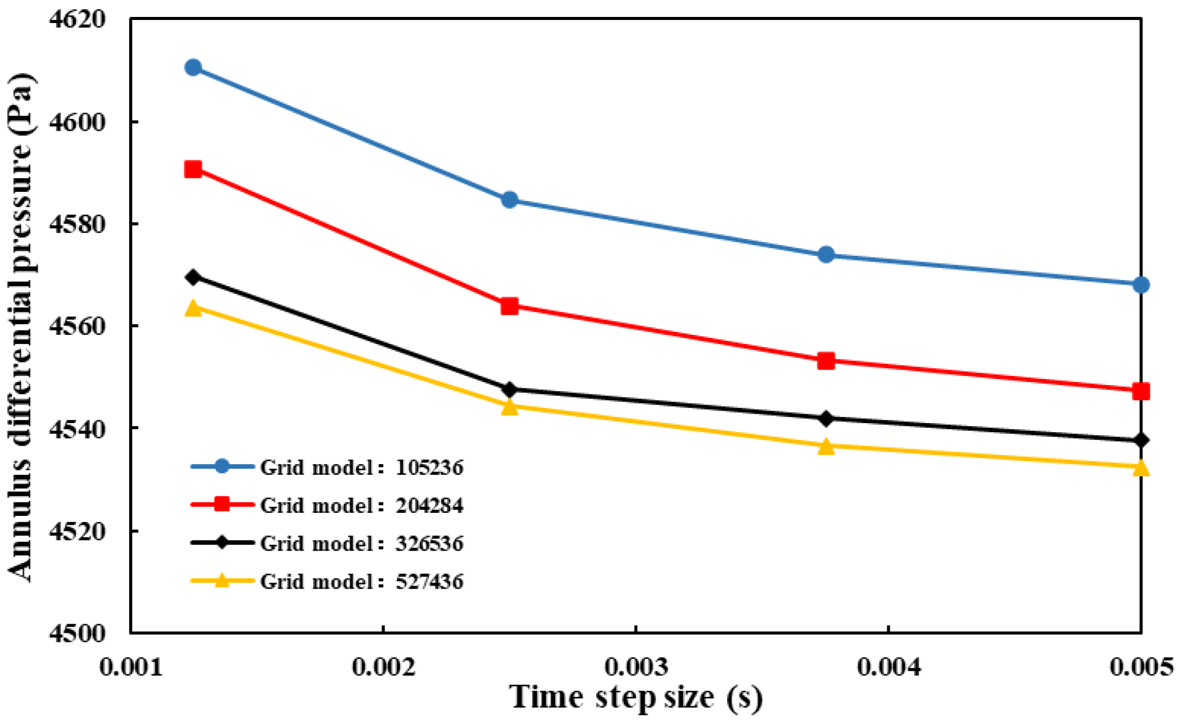
2.3. Computational Mesh and Grid Refinement Assessment

We performed a grid invariance test with four different grid numbers and time steps, considering the large difference in the results of numerical simulations under different grid numbers along with the computation cost. The findings are presented in Figure 3. When the time step is 0.0025 s, the maximum pressure drop difference between a grid with 527,436 numbers and the grid with 326,536 numbers is less than 0.2%. Therefore, we chose a grid with 326,232 numbers and a time step of 0.0025 s for this study, and we performed twenty iterations in each time step.
A hexahedron-structured mesh was used to mesh the geometric modeling. The near-wall surface was treated with a standard wall function. The grid division of the boundary layer met the condition y+ ≈ 30, and we divided the near wall of the drill pipe and wellbore into grids through local encryption. Figure 4 shows the schematic diagram of the grid division of the geometric model.

3. Results and Analysis

3.1. Simulation and Experimental Comparison to Validate the Model

To validate the numerical simulation results, we compared them with experimental data and results from the literature. Figure 5 shows the comparison of numerical simulation results and [44] experimental results for the annular pressure drop with different drilling fluid flow rates under Eulerian two-fluid conditions. The results show that the numerical simulation results have an average error of 9.62% compared to the existing experimental data, which indicates high agreement. Under Eulerian two-fluid conditions, this model can accurately predict cuttings transport behavior.

3.2. Effect of Drilling Fluid Circulation Return Speed on Borehole Cleaning

Figure 6 shows the relationship between the drilling fluid circulation return speed and cuttings volume fraction under different borehole conditions. It is clear that for both conventional boreholes and boreholes with enlarged sections the cuttings volume fraction decreases with the increase of the drilling fluid circulation return speed. At the same time, under the same drilling fluid circulation return speed condition the fraction of cuttings volume grows as the enlargement rate rises. When the drilling fluid circulation return speed increases from 0.5 m/s to 1.25 m/s, the overall annular cuttings volume fraction reduction of the conventional borehole, enlarged borehole with enlargement rate of 0.4, and enlarged borehole with enlargement rate of 0.7 are 8.98%, 5.26%, and 4.35%, respectively. The slope of the cuttings volume fraction trend line of the conventional boreholes is 1.82 times that of the enlarged borehole with an enlargement rate of 0.4 and 2.19 times that of the enlarged borehole with an enlargement rate of 0.7. This indicates that increasing the drilling fluid circulation return speed can effectively improve the cleaning effect for a conventional borehole under the same conditions, while it has limited improvement effect on the borehole cleaning effect for horizontal wells with enlarged sections; moreover, the improvement effect of borehole cleaning becomes worse with a greater enlargement rate.
Figure 7 illustrates the cuttings flow in different directions as the drilling fluid circulation speed varies in an enlarged wellbore and in a conventional wellbore with an enlargement ratio of 0.4. Generally, more cuttings are present in the enlarged area of the annulus of the enlarged wellbore, while the conventional wellbore has a more even distribution of cuttings. In the enlarged wellbore, when cuttings enter the enlarged section with the drilling fluid the well diameter suddenly increases and the axial flow velocity of the drilling fluid drops sharply. Cuttings in the annulus then settle under gravity and form a cuttings bed. A fixed cuttings bed forms slowly, as the drilling fluid cannot provide kinetic energy to the cuttings effectively at the annulus bottom. As the flow rate increases, the cuttings in the annulus of the enlarged wellbore with the enlarged section are concentrated in the enlarged section; while the total amount of cuttings is almost unchanged, in the conventional well section the amount of cuttings deposition decreases significantly with increasing flow rate. Under a high flow rate, cleaning of the conventional wellbore has a good effect, while the cleaning effect for the enlarged wellbore with the enlarged section is very poor.
The particles have three modes of axial movement on the face of the cuttings deposit: sliding, rotating, and lifting. When the fluid driving force in the axial direction is greater than the frictional resistance of the particle the particle slides, and when the destabilizing moment of the particle around its rotation pivot point is greater than the stabilizing moment, the particle rolls and moves; when the particle moves to the junction between the dilated section and the non-dilated section, the particle cannot move forward using the force of the wall, and accumulates at the junction. In lifting mode, the lifting force on the particles exceeds their floating weight, and the particles become suspended in the drilling fluid to a height greater than the height of the junction between the expanded and non-expanded sections. At the end of the enlargement section the well diameter suddenly decreases, creating a height difference between the enlargement section and the non-enlargement section. This blocks the forward movement of cuttings in sliding and rolling modes and makes them stay in the enlargement section. Cuttings in lifting mode fall back into the enlargement section if their lifting height is lower than that of the non-enlargement section. As cuttings accumulate in the enlargement section, the height difference between the cuttings bed surface and the non-enlargement section shrinks. When they are equal, cuttings in sliding and rolling modes can resume moving forward. As the drilling fluid circulation return speed increases, the cuttings concentration in the conventional well section decreases gradually; however, many cuttings remain in the enlarged section of the enlarged wellbore. This results in poor hole cleaning and hampers normal drilling.

3.3. Effect of Drill Pipe Spinning Rate on Borehole Cleaning

The cuttings volume fraction under different wellbore conditions is affected by the drill pipe spinning rate, as shown in Figure 8. As shown, the cuttings volume fraction decreases as the drill pipe rotation speed increases under any wellbore conditions. When the drill pipe spinning rate rises from 0 rpm to 180 rpm, the cuttings volume fraction drops by 4.57%, 2.83%, and 1.80% for the conventional wellbore, enlarged wellbore with enlargement ratio of 0.4, and enlarged wellbore with enlargement ratio of 0.7, respectively. When the drill pipe rotation rate is 0 rpm, the cuttings volume fraction of the enlarged wellbore with an enlargement ratio of 0.7 is 2.15 times that of the conventional wellbore and 1.46 times that of the enlarged wellbore with an enlargement ratio of 0.4. When the drill pipe rotation rate is 180 rpm, the cuttings volume fraction of the enlarged wellbore with an enlargement ratio of 0.7 is 3.176 times that of the conventional wellbore and 1.66 times that of the enlarged wellbore with an enlargement ratio of 0.4. The cuttings volume fraction trend line of the conventional wellbore has a slope that is 1.72 times higher than that of the enlarged wellbore with an enlargement ratio of 0.4 and 2.77 times that of the enlarged wellbore with an enlargement ratio of 0.7. This means that under the same conditions the conventional wellbore has a better hole cleaning effect with faster drill pipe rotation, while horizontal wells with enlarged well sections show a limited improvement in the hole cleaning effect with faster drill pipe spinning and the improvement impact worsens as the enlargement ratio increases. When the enlargement ratio is too high, drill pipe spinning cannot enhance the borehole cleaning effect of horizontal wells with enlarged well sections.
Figure 9 illustrates the three-dimensional surface of tangential velocity with projection at the z = 2 m section of the enlarged wellbore and conventional wellbore with an enlargement ratio of 0.4. As shown, under the same conditions the enlarged wellbore and conventional wellbore have the same maximum fluid velocity in the tangential direction. At the wall of the drill pipe, the drilling fluid tangential velocity is the highest, where it is sheared by drill pipe rotation, while the tangential velocity decreases radially. Due to the drill pipe’s eccentricity, at the nadir of the doughnut-shaped area the drilling fluid has its maximum tangential velocity at the wall-adjacent side of the drill pipe. The area of drilling fluid with high tangential kinetic energy in the annulus expands as the drill pipe rotation speed increases. When cuttings pile up at the bottom of the annulus, they form a fixed cuttings bed area. The drilling fluid transfers tangential kinetic energy to cuttings on the surface of the fixed cuttings bed and effectively moves them. The drag force, lift force, buoyancy force, and gravity force remain unchanged under the action of drill stem rotation, and the friction force is increased by the centrifugal force. The drill stem rotation increases the tangential force of the particles and drives the particles to make a circumferential motion. For a conventional wellbore, faster rotation speed increases the circumferential lifting force around the cuttings bed surface, improves drilling fluid suspension ability, reduces cuttings deposition, and lowers the height of the cuttings bed. However, for the enlarged well section the cuttings are mainly in the enlarged area, and the drilling fluid kinetic energy near the surface of the fixed cuttings bed in the enlarged section is much lower than that in the conventional well section. Most particles start to move circumferentially in sliding mode under drill pipe rotation, which hinders the movement of cuttings out of the enlarged section. When the cuttings bed surface height in enlarged section is lower than that in the non-enlarged section, cuttings struggle to move out of the enlarged section under drill pipe rotation. Therefore, drill pipe rotation hardly helps in hole cleaning of horizontal wells with enlarged well sections.

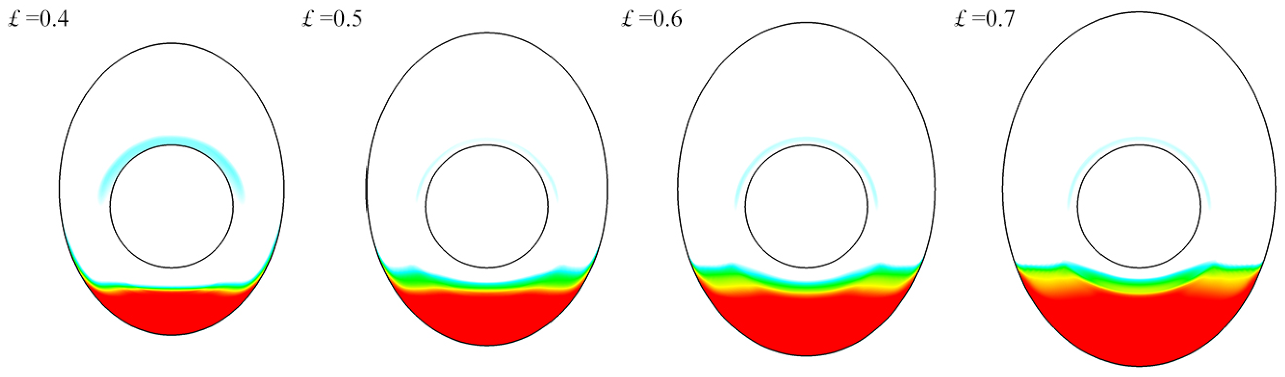
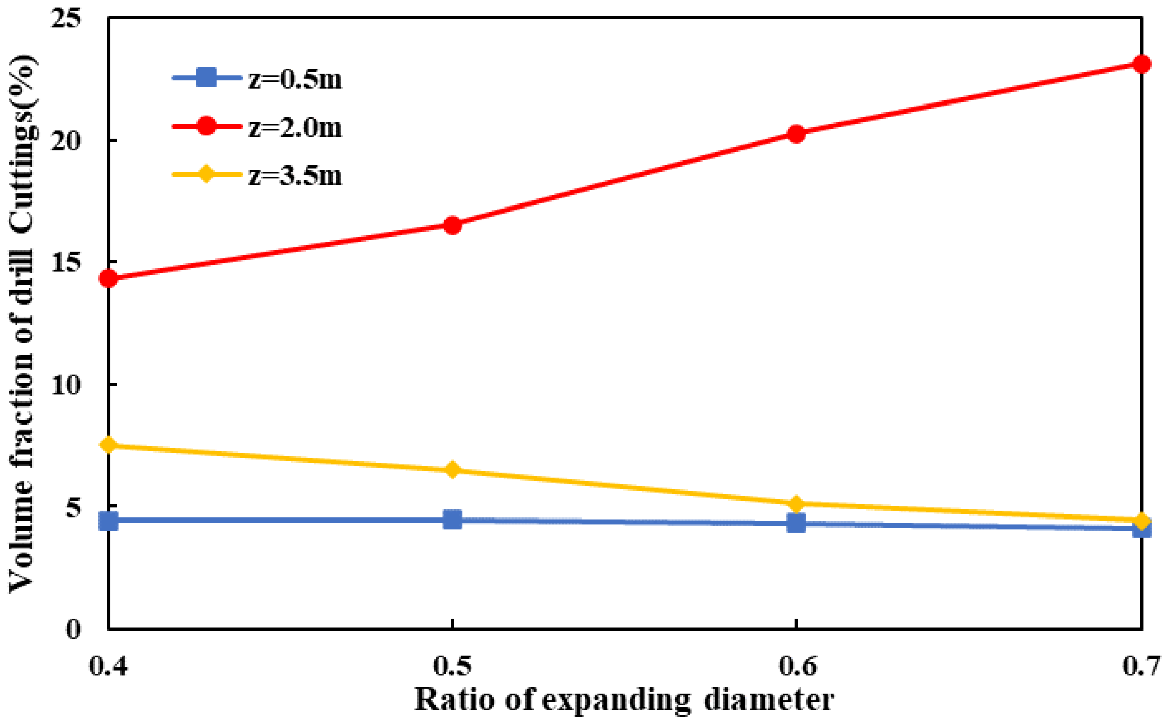
3.4. Effect of Enlargement Ratio on Hole Cleaning

Figure 10 illustrates the cuttings distribution profile of the enlarged well section of the horizontal well with different enlargement ratios. As shown, the cuttings deposition in the enlarged well section grows as the enlargement ratio increases. The annulus area of the enlarged well section expands with the enlargement ratio. When the enlargement ratio is 0.7, the annulus area of the enlarged well section is 3.06 times that of the enlargement ratio of 0.4. Therefore, a higher enlargement ratio means lower drilling fluid velocity in the enlarged area and easier cuttings deposition. As the drilling fluid speed decreases, the drag force on the particles decreases as well; in these conditions it is difficult for the particles to overcome the frictional resistance of the particles, and sliding cannot occur. The height difference between the enlarged section and the non-enlarged section rises with the enlargement ratio. The height difference when the enlargement ratio is 0.7 is 1.75 times that of the enlargement ratio of 0.4. The greater the height difference, the more difficult it is for cuttings to move out of the enlarged section. Because the bottom annulus area is bigger, the same amount of cuttings deposition has a smaller cuttings bed height in annulus with a high enlargement ratio, which makes it harder for cuttings to move out of the enlarged section and results in a very poor hole cleaning effect under the high enlargement ratio.
Figure 11 illustrates how the enlargement ratio affects the cuttings volume fraction at different axial positions of horizontal wells with enlarged well sections. As shown, the cuttings volume fraction at z = 0.5 m stays almost the same as the enlargement ratio increases, the cuttings volume fraction at z = 2.0 m rises significantly, and the cuttings volume fraction at z = 3.5 m drops. The enlargement degree has little impact on cuttings movement at the wellbore entrance; however, the challenge of ensuring cuttings movement out of the enlarged section grows with the enlargement ratio. A higher enlargement ratio means easier cuttings deposition in the enlarged sections. When the enlargement ratio is low, the cuttings volume fraction at the wellbore exit is slightly higher than that of the wellbore exit with high enlargement ratio, as more cuttings are moved out of the enlarged section.

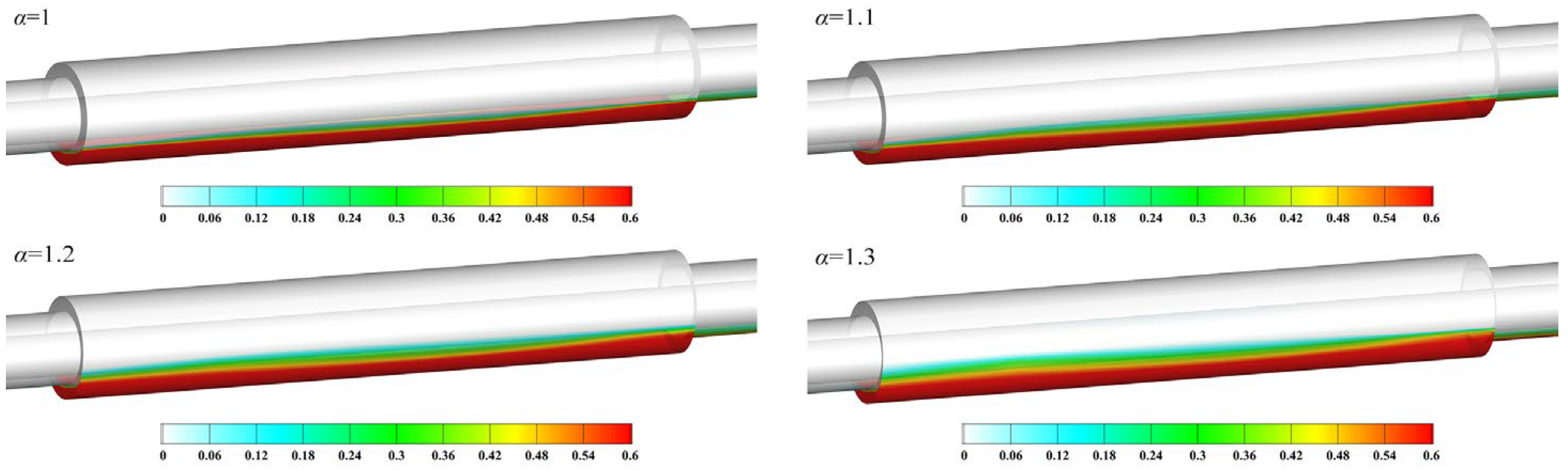
3.5. Effect of Ovality on Hole Cleaning

Figure 12 illustrates how the cuttings volume fraction of horizontal wells with enlarged sections varies with ellipticity and enlargement rate. The cuttings volume fraction increases as the ellipticity increases, and is higher for larger enlargement rates. For ex-ample, when the enlargement rate is 0.4 the cuttings volume fraction of ellipticity 1.3 is 4.3% higher than that of ellipticity 1. The area of cuttings accumulation is reduced when the ellipticity increases. If the cuttings bed and the drill pipe have no contact, the area of the cuttings accumulation ratio of ellipticity 1 and ellipticity 1.3 is 0.77; when the drill pipe is partially submerged in the cuttings bed, the cuttings bed surface area ratio of ellipticity 1 and ellipticity 1.3 first decreases and then increases, reaching a minimum of 0.42; and when the drill pipe is completely submerged in the cuttings bed, the area ratio is the same as when the cuttings bed does not touch the drill pipe. With increasing eccentricity the momentum exchange efficiency between the fluid and the cuttings bed is lower, and the wellbore cleaning effect is less good.
Figure 13 illustrates how the cuttings volume fraction of horizontal wells with enlarged sections varies with the ellipticity and enlargement rate. The cuttings volume fraction increases as the ellipticity increases, and is higher for larger enlargement rates. For example, when the enlargement rate is 0.4, the cuttings volume fraction of ellipticity 1.3 is 4.3% higher than that of ellipticity 1. The drilling fluid touches less of the cuttings bed surface. When the drill pipe is completely located in the drilling fluid, the area of the cuttings accumulation ratio of ellipticity 1 and ellipticity 1.3 is 0.77, while when the drill pipe is partially located in the drilling fluid, the area of the cuttings accumulation ratio of ellipticity 1 and ellipticity 1.3 first decreases and then increases, reaching a minimum of 0.42. The area ratio is unchanged when the drill pipe is buried in the cuttings and the drilling fluid does not touch it or the cuttings bed. A higher ellipticity reduces the momentum exchange between the fluid and particles, meaning that the fluid driving force along the axial direction is smaller than the frictional resistance of particles, while the destabilizing moment at the rotational pivot point of particles is smaller than the stabilizing moment and worsens the borehole cleaning effect.

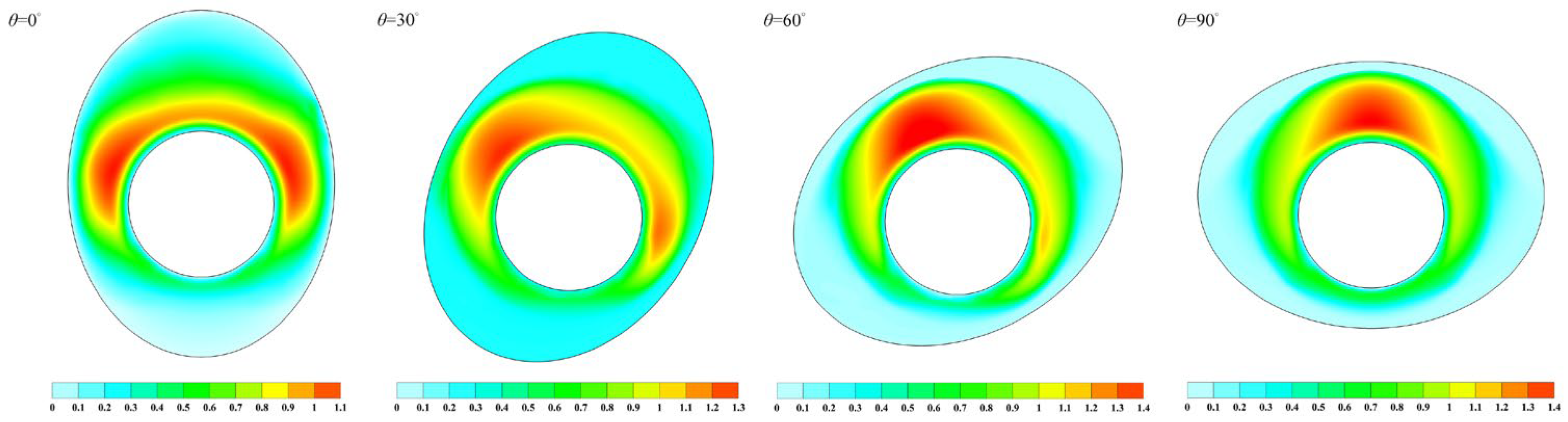
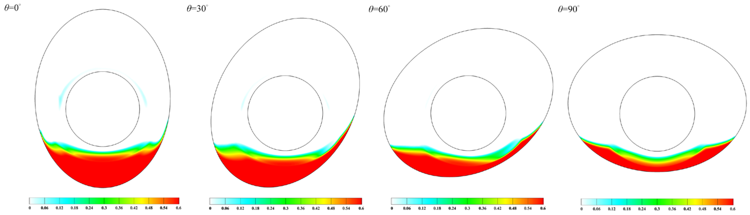
3.6. Effect of Principal Axis Bearing Angle on Hole Cleaning

Figure 14 illustrates how the drilling fluid moves along the axis of horizontal wells where the section is bigger with an enlargement rate of 0.4 and changes with different major axis orientation angles. The high-speed core area of the drilling fluid is closer to the elliptical short axis, where the drill pipe and the well wall are nearer. The area with the fast core is much wider at the short axis than at the long axis. The cuttings bed lowers the axial velocity at the bottom of the annulus and clogs the drilling fluid channel. When θ is 0°, both sides of the short axis have high-speed core areas of drilling fluid. As θ increases, the short axis aligns with the gravity direction. The fast core area near the bottom of the annulus on the short axis becomes smaller as cuttings accumulate. When θ is 90°, only the short axis at the upper part of the annulus has a high-speed core area of drilling fluid, while the short axis at the lower part of the ring-shaped space has none.
Figure 15 illustrates how the cuttings distribution of horizontal wells with enlarged sections with an enlargement rate of 0.4 changes with different major axis orientation angles. The height difference between the enlarged section and the non-enlarged section decreases as θ increases. When θ increases from 0° to 90°, the height difference drops from 43.18 mm to 8.3 mm, a decrease of 80.78%. This makes the cuttings bed lower in the bigger section and lets the particles on the exterior of the cuttings bed be taken away by slipping and rolling, improving the hole cleaning efficiency significantly. The cuttings volume fraction decreases by 0.96% when θ increases from 0° to 30°, by 3.07% when θ increases from 30° to 60°, and by 1.41% when θ increases from 60° to 90°. The hole cleaning effect is the best when θ increases from 30° to 60°. This is because as θ increases, the cuttings bed height in the enlarged section and the rapid core region of drilling fluid in the annulus both decrease. The combined effect of these two factors creates this pattern.
Figure 16 illustrates how the cuttings volume fraction of horizontal wells with enlarged sections changes with different major axis orientation angles under different enlargement rates. The cuttings volume fraction decreases as the major axis orientation angle increases. The more the section expands, the less the cuttings volume fraction drops. For example, when the major axis orientation angle increases from 0° to 90°, the cuttings volume fraction for enlargement rates of 0.4, 0.5, 0.6, and 0.7 decreases by 5.43%, 4.67%, 3.86%, and 2.61%, respectively. When the enlargement rate is 0.4 and when θ increases from 0° to 90°, the height difference drops from 43.18 mm to 8.3 mm, a decrease of 80.78%. When the enlargement rate is 0.7 and when the major axis orientation angle increases from 0° to 90°, the height difference between the enlarged section and the non-enlarged section drops from 75.57 mm to 33.22 mm, a drop of 43.96%. This makes it hard for the cuttings to be removed from the enlarged section. When the lifting force on the particle is constant with the floating weight component of the particle, the lifting height of the particle under the action of these two forces is constant and the increase in height difference makes the particle more susceptible to the force of the wall, increasing the difficulty of particle transport. The major axis orientation angle has a small impact on improving the cuttings volume fraction in horizontal wells with enlarged sections under high enlargement rates.

4. Conclusions

This study examines how horizontal wellbores with and without bigger sections can transport cuttings under different rates of drilling fluid circulation and drill pipe spinning. In addition, it models the effects of different rates of section expansion, ellipticities, and angles of major axis orientation on the efficiency of hole cleaning in horizontal wellbores with bigger sections.
(1)
Increasing the drilling fluid circulation rate has a limited impact on improving the wellbore cleaning effect of horizontal wells with enlarged sections, and the impact is smaller for higher enlargement rates; the hole cleaning effect of horizontal wells with bigger sections is barely improved by enhancing the rate of drill pipe spinning, and hardly affected at all when the rate of section expansion is too high.
(2)
When the enlargement ratio is 0.7, the annulus area of the enlarged well section is 3.06 times that of the enlargement ratio of 0.4. The higher the enlargement rate, the harder it is for the cuttings to be removed from the enlarged section, and the worse the borehole cleaning impact is for horizontal wells with enlarged sections under high enlargement rates.
(3)
When the enlargement rate is 0.4, the cuttings volume fraction of ellipticity 1.3 is 4.3% higher than that of ellipticity 1. As the ellipticity increases, fewer cuttings directly exchange enough momentum with the fluid, worsening the cleaning effect in the borehole expansion area.
(4)
The cuttings volume fraction decreases by 0.96% when θ increases from 0° to 30°, by 3.07% when θ increases from 30° to 60°, and by 1.41% when θ increases from 60° to 90°. With a higher major axis orientation angle, it is easier for the cuttings to be removed from the enlarged section, and the same number of cuttings in the bigger section form a cuttings bed with a lower height. The hole cleaning effect improves the most when θ increases from 30° to 60°.

Author Contributions

Methodology, X.S.; software, L.T. and J.Q.; validation, D.Y.; writing—original draft preparation, L.T. and Y.Z.; writing—review and editing, L.T. and Z.L. All authors have read and agreed to the published version of the manuscript.

Funding

This work was supported by Hainan Province Science and Technology Special Fund (No. ZDYF2022SHFZ063) and the National Natural Science Foundation of China (Grant Nos. 52174002, 52204008).

Data Availability Statement

Not applicable.

Conflicts of Interest

The authors declare no conflict of interest.

References

  1. Mahmoud, H.; Hamza, A.; Nasser, M.S.; Hussein, I.A.; Ahmed, R.; Karami, H. Hole Cleaning and Drilling Fluid Sweeps in Horizontal and Deviated Wells: Comprehensive Review. J. Pet. Sci. Eng. 2020, 186, 106748. [Google Scholar] [CrossRef]
  2. Mendez, M.; Ahmed, R.; Karami, H.; Nasser, M.; Hussein, I.; Garcia, S.; Gonzalez, A. Applications of Machine Learning Methods to Predict Hole Cleaning in Horizontal and Highly Deviated Wells. In SPE/ICoTA Well Intervention Conference and Exhibition; OnePetro: Richardson, TX, USA, 2023. [Google Scholar] [CrossRef]
  3. Skenderija, J.; Koulidis, A.; Sanchez, D.L.; Ahmed, S. Advanced Hole Cleaning in Horizontal Wells: Experimental Investigation Supported by a Downhole Clamp-On Tool. In Middle East Oil, Gas and Geosciences Show; OnePetro: Richardson, TX, USA, 2023. [Google Scholar] [CrossRef]
  4. Hirpa, M.M.; Kuru, E. Hole Cleaning in Horizontal Wells Using Viscoelastic Fluids: An Experimental Study of Drilling-Fluid Properties on the Bed-Erosion Dynamics. SPE J. 2020, 25, 2178–2193. [Google Scholar] [CrossRef]
  5. Ruzhnikov, A.; Echevarria, E. Wellbore Cleanness under Total Losses in Horizontal Wells: The Field Study. In Abu Dhabi International Petroleum Exhibition and Conference; SPE: Calgary, AB, Canada, 2021; pp. 15–18. [Google Scholar] [CrossRef]
  6. Joshi, S.D.; International, J.T. Cost/Benefits of Horizontal Wells. In SPE Western Regional Meeting; SPE: Calgary, AB, Canada, 2003; p. SPE-83621. [Google Scholar]
  7. Busahmin, B.; Saeid, N.H.; Alusta, G.; Zahran, E.S.M.M. Review on Hole Cleaning for Horizontal Wells. ARPN J. Eng. Appl. Sci. 2017, 12, 4697–4708. [Google Scholar]
  8. Al Rubaii, M.M. A New Robust Approach for Hole Cleaning to Improve Rate of Penetration. In SPE Kingdom of Saudi Arabia Annual Technical Symposium and Exhibition; SPE: Calgary, AB, Canada, 2018. [Google Scholar] [CrossRef]
  9. Azevedo, L.F.A.; Braga, A.M.B.; Nieckele, A.O.; Naccache, M.F.; Gomes, M.G.F.M. Simple Hydrodynamic Models for the Prediction of Pig Motions in Pipelines. Proc. Annu. Offshore Technol. Conf. 1996, 4, 729–739. [Google Scholar] [CrossRef]
  10. Bilgesu, H.I.; Ali, M.W.; Aminian, K.; Ameri, S. Computational Fluid Dynamics (CFD) as a Tool to Study Cutting Transport in Wellbores. In SPE Eastern Regional Meeting; SPE: Calgary, AB, Canada, 2002; pp. 155–158. [Google Scholar] [CrossRef]
  11. Boghi, A.; Brown, L.; Sawko, R.; Thompson, C.P. An Inertial Two-Phase Model of Wax Transport in a Pipeline during Pigging Operations. Int. J. Multiph. Flow 2017, 94, 17–30. [Google Scholar] [CrossRef] [Green Version]
  12. Boghi, A.; Brown, L.; Sawko, R.; Thompson, C.P. A Non-Inertial Two-Phase Model of Wax Transport in a Pipeline during Pigging Operations. J. Pet. Sci. Eng. 2018, 165, 664–672. [Google Scholar] [CrossRef] [Green Version]
  13. Dabiri Atashbeyk, M.; Shahbazi, K.; Fattahi, M. Pressure Profile Estimation through CFD in UBD Operation Considering with Influx to Wellbore. Iran. J. Chem. Chem. Eng. 2018, 37, 271–283. [Google Scholar]
  14. Jackson, G.T.; Balhoff, M.T.; Huh, C.; Delshad, M. CFD-Based Representation of Non-Newtonian Polymer Injectivity for a Horizontal Well with Coupled Formation-Wellbore Hydraulics. J. Pet. Sci. Eng. 2011, 78, 86–95. [Google Scholar] [CrossRef] [Green Version]
  15. Li, X.; Zhang, J.; Tang, X.; Mao, G.; Wang, P. Study on Wellbore Temperature of Riserless Mud Recovery System by CFD Approach and Numerical Calculation. Petroleum 2020, 6, 163–169. [Google Scholar] [CrossRef]
  16. Szanyi, M.L.; Hemmingsen, C.S.; Yan, W.; Walther, J.H.; Glimberg, S.L. Near-Wellbore Modeling of a Horizontal Well with Computational Fluid Dynamics. J. Pet. Sci. Eng. 2018, 160, 119–128. [Google Scholar] [CrossRef] [Green Version]
  17. Dewangan, S.K.; Sinha, S.L. Exploring the Hole Cleaning Parameters of Horizontal Wellbore Using Two-Phase Eulerian CFD Approach. J. Comput. Multiph. Flows 2016, 8, 15–39. [Google Scholar] [CrossRef] [Green Version]
  18. Hu, Q.; Li, Y.; Sun, X.; Chen, M.; Bu, Q.; Gong, B. Integrating Test Device and Method for Creep Failure and Ultrasonic Response of Methane Hydrate-Bearing Sediments. Rev. Sci. Instrum. 2023, 94, 025105. [Google Scholar] [CrossRef] [PubMed]
  19. Abbas, A.K.; Alsaba, M.T.; Al Dushaishi, M.F. Comprehensive Experimental Investigation of Hole Cleaning Performance in Horizontal Wells Including the Effects of Drill String Eccentricity, Pipe Rotation, and Cuttings Size. J. Energy Resour. Technol. Trans. ASME 2022, 144, 063006. [Google Scholar] [CrossRef]
  20. Kristiansen, T.G.; Bauer, A.; Guida, A.; Bonin, C. A Troublesome Well Section: The Rock Mechanics Analysis. In SPE Norway Subsurface Conference? SPE: Calgary, AB, Canada, 2022. [Google Scholar] [CrossRef]
  21. Mahmoud, H.; Alhajabdalla, M.; Nasser, M.S.; Hussein, I.A.; Ahmed, R.; Karami, H. Settling Behavior of Fine Cuttings in Fiber-Containing Polyanionic Fluids for Drilling and Hole Cleaning Application. J. Pet. Sci. Eng. 2021, 199, 108337. [Google Scholar] [CrossRef]
  22. Ma, Y.; Yang, C.; Liu, X. On Hole Cleaning Evaluation Method in Highly Deviated/Horizontal Well Sections. J. Phys. Conf. Ser. 2023, 2442, 012037. [Google Scholar] [CrossRef]
  23. Bilgesu, H.I.; Mishra, N.; Ameri, S. Understanding the Effects of Drilling Parameters on Hole Cleaning in Horizontal and Deviated Wellbores Using Computational Fluid Dynamics. In Eastern Regional Meeting; SPE: Calgary, AB, Canada, 2007; pp. 206–212. [Google Scholar] [CrossRef]
  24. Ozbayoglu, M.E.; Saasen, A.; Sorgun, M.; Svanes, K. Effect of Pipe Rotation on Hole Cleaning for Water-Based Drilling Fluids in Horizontal and Deviated Wells. In IADC/SPE Asia Pacific Drilling Technology Conference and Exhibition? SPE: Calgary, AB, Canada, 2008; pp. 332–342. [Google Scholar] [CrossRef]
  25. Li, S.; Chen, Z.; Li, W.; Yan, T.; Bi, F.; Tong, Y. An FE Simulation of the Fracture Characteristics of Blunt Rock Indenter Under Static and Harmonic Dynamic Loadings Using Cohesive Elements. Rock Mech. Rock Eng. 2023, 56, 2935–2947. [Google Scholar] [CrossRef]
  26. Li, Y.; Tang, B.; Geng, B.; Jiao, S. Fractional Order Fuzzy Dispersion Entropy and Its Application in Bearing Fault Diagnosis. Fractal Fract. 2022, 6, 544. [Google Scholar] [CrossRef]
  27. Liu, H. Geophysics Principles and Applications of Well Logging, 2nd ed.; Springer: Berlin/Heidelberg, Germany, 2017; ISBN 9783662549766. [Google Scholar]
  28. McLellan, P.J. Assessing the Risk of Wellbore Instability in Horizontal and Inclined Wells. J. Can. Pet. Technol. 1996, 35, 21–32. [Google Scholar] [CrossRef]
  29. Pierdominici, S.; Millett, J.M.; Kück, J.K.M.; Thomas, D.; Jerram, D.A.; Planke, S.; Haskins, E.; Lautze, N.; Galland, O. Stress Field Interactions Between Overlapping Shield Volcanoes: Borehole Breakout Evidence From the Island of Hawai’i, USA. J. Geophys. Res. Solid Earth 2020, 125, e2020JB019768. [Google Scholar] [CrossRef]
  30. Ju, G.; Yan, T.; Sun, X. Numerical Simulation of Effective Hole Cleaning by Using an Innovative Elliptical Drillpipe in Horizontal Wellbore. Energies 2022, 15, 399. [Google Scholar] [CrossRef]
  31. Yan, T.; Qu, J.; Sun, X.; Chen, Y.; Hu, Q.; Li, W.; Zhang, H. Numerical Investigation on Horizontal Wellbore Hole Cleaning with a Four-Lobed Drill Pipe Using CFD-DEM Method. Powder Technol. 2020, 375, 249–261. [Google Scholar] [CrossRef]
  32. Chen, Y.; Zhang, H.; Li, J.; Zhou, Y.; Lu, Z.; Ouyang, Y.; Tan, T.; Liu, K.; Wang, X.; Zhang, G. Simulation Study on Cuttings Transport of the Wavy Wellbore Trajectory in the Long Horizontal Wellbore. J. Pet. Sci. Eng. 2022, 215, 110584. [Google Scholar] [CrossRef]
  33. Fallah, A.H.; Gu, Q.; Saini, G.; Chen, D.; Ashok, P.; Van Oort, E.; Vajargah, A.K. Hole Cleaning Case Studies Analyzed with a Transient Cuttings TransportModel. In SPE Annual Technical Conference and Exhibition? SPE: Calgary, AB, Canada, 2020. [Google Scholar] [CrossRef]
  34. Khan, M.S.; Barooh, A.; Khan, M.Y.; Aziz ur Rahman, M.; Hassan, I.; Hassan, R. Investigating Non-Newtonian Multiphase Cutting Transport in an Extended Reach Well. In SPE Conference at Oman Petroleum & Energy Show; SPE: Calgary, AB, Canada, 2022. [Google Scholar] [CrossRef]
  35. Mokhtari, M.; Tutuncu, A.N.; Teklu, T.W. A Numerical Modeling Study for the Impact of Casing Drilling on Wellbore Stability. In SPE Canada Unconventional Resources Conference? SPE: Calgary, AB, Canada, 2013; Volume 1, pp. 549–558. [Google Scholar] [CrossRef]
  36. Ghazanfari, V.; Imani, M.; Shadman, M.M.; Amini, Y.; Zahakifar, F. Numerical Study on the Thermal Performance of the Shell and Tube Heat Exchanger Using Twisted Tubes and Al2O3 Nanoparticles. Prog. Nucl. Energy 2023, 155, 104526. [Google Scholar] [CrossRef]
  37. Walton, O.R.; Braun, R.L. Viscosity, Granular-temperature, and Stress Calculations for Shearing Assemblies of Inelastic, Frictional Disks. J. Rheol. 1986, 30, 949–980. [Google Scholar] [CrossRef]
  38. Brilliantov, N.V.; Pöschel, T. Rolling Friction of a Viscous Sphere on a Hard Plane. Europhys. Lett. 1998, 42, 511–516. [Google Scholar] [CrossRef] [Green Version]
  39. Mathiesen, V.; Solberg, T.; Hjertager, B.H. Predictions of Gas/Particle Flow with an Eulerian Model Including a Realistic Particle Size Distribution. Powder Technol. 2000, 112, 34–45. [Google Scholar] [CrossRef]
  40. Lun, C.K.K.; Savage, S.B.; Jeffrey, D.J.; Chepurniy, N. Kinetic Theories for Granular Flow: Inelastic Particles in Couette Flow and Slightly Inelastic Particles in a General Flowfield. J. Fluid Mech. 1984, 140, 223–256. [Google Scholar] [CrossRef]
  41. Huilin, L.; Gidaspow, D.; Bouillard, J.; Wentie, L. Hydrodynamic Simulation of Gas-Solid Flow in a Riser Using Kinetic Theory of Granular Flow. Chem. Eng. J. 2003, 95, 1–13. [Google Scholar] [CrossRef]
  42. Schiller, A.N.L. Über Die Grundlegenden Berechnungen Beider Schwerkraftaufbereitung. Z. Ver. Dtsch. Ing. 1933, 77, 318–320. [Google Scholar]
  43. Sarmadi, P.; Renteria, A.; Thompson, C.; Frigaard, I.A. Effects of Wellbore Irregularity on Primary Cementing of Horizontal Wells, Part 2: Small Scale Effects. J. Pet. Sci. Eng. 2022, 210, 110026. [Google Scholar] [CrossRef]
  44. Han, S.M.; Hwang, Y.K.; Woo, N.S.; Kim, Y.J. Solid-Liquid Hydrodynamics in a Slim Hole Drilling Annulus. J. Pet. Sci. Eng. 2010, 70, 308–319. [Google Scholar] [CrossRef]
Figure 1. Three-dimensional borehole breakout view from ABI image of the borehole wall; Sh and SH are the orientations of the minimum and maximum horizontal principal stresses, respectively. (Simona Pierdominici, 2020 [29]).
Mathematics 11 03070 g001
Figure 2. Shape parameters and working conditions in the numerical simulation.
Mathematics 11 03070 g002
Figure 3. Grid independence test and time independence verification.
Mathematics 11 03070 g003
Figure 4. Computational domain and grid schematic: (a) schematic of the mesh in the unexpanded section of the hole with expanded section; (b) schematic of the mesh in the expanded section of the hole with expanded section; (c) schematic of mesh of the hole with expanded section; (d) schematic of the mesh of a conventional drill hole.
Mathematics 11 03070 g004
Figure 5. Validation of present prediction with experimental results from Han [44].
Mathematics 11 03070 g005
Figure 6. Relationship between drilling fluid circulation velocity and cuttings volume fraction under different borehole conditions.
Mathematics 11 03070 g006
Figure 7. Effect of different drilling fluid circulation velocities on cuttings volume fraction under different borehole conditions.
Mathematics 11 03070 g007
Figure 8. Effect of drill pipe spinning rate on cuttings volume fraction under different borehole conditions.
Mathematics 11 03070 g008
Figure 9. Three-dimensional surface diagrams of the tangential velocity with projection at the z = 2 m section of the expanded borehole with an expansion ratio of 0.4 and the conventional wellbore.
Mathematics 11 03070 g009
Figure 10. Cuttings distribution profile of expanded well section under different expansion ratios a in horizontal well with an expanded section.
Mathematics 11 03070 g010
Figure 11. Effect of expansion rate on cuttings volume fraction at different axial positions in a horizontal well with expansion section.
Mathematics 11 03070 g011
Figure 12. Effect of expansion rate on cuttings volume fraction at different ovalities in a horizontal well with expansion section.
Mathematics 11 03070 g012
Figure 13. Cuttings distribution along the flow direction of the expanded well section under different ellipticities in a horizontal well with an expanded section with an expansion ratio of 0.4.
Mathematics 11 03070 g013
Figure 14. Axial velocity profiles of drilling fluid at different main axis azimuths for a horizontal well with an expansion ratio of 0.4.
Mathematics 11 03070 g014
Figure 15. Cuttings distribution profiles at different main axis azimuths in a horizontal well with an expansion ratio of 0.4.
Mathematics 11 03070 g015
Figure 16. Effect of expansion rate on cuttings volume fraction at different principal axis bearing angle in a horizontal well with expansion section.
Mathematics 11 03070 g016
Table 1. Geometrical parameters and operating conditions in the numerical simulation.
VariablesValues
Annulus Length, L (m)4
Enlarged annulus Length, L1 (m)2
Angle of inclination, θ1 (deg)90
Pipe diameter, D0 (mm)127
Conventional Hole diameter, D1 (mm)215.9
Eccentricity, e0.4
Fluid density, ρl (kg/m3)1600
Drilling Fluid circulation velocity, v (m/s)0.5, 0.75, 1, 1.25
Drill pipe rotational speed, n0 (rpm)0, 60, 120, 180
Ratio of expanding diameter, £0.4, 0.5, 0.6, 0.7
Ovality, α1, 1.1, 1.2, 1.3
Principal axis bearing angle, θ (deg)0, 30, 60, 90
Disclaimer/Publisher’s Note: The statements, opinions and data contained in all publications are solely those of the individual author(s) and contributor(s) and not of MDPI and/or the editor(s). MDPI and/or the editor(s) disclaim responsibility for any injury to people or property resulting from any ideas, methods, instructions or products referred to in the content.

