Abstract
This paper investigates the observer-based adaptive stabilization control problem for a class of time-delay nonlinear systems with unknown control gain using an echo state network (ESN). In order to handle unknown functions, a new recurrent neural network (RNN) approximation method called ESN is utilized. It improves accuracy, reduces computing cost, and is simple to train. To address the issue of unknown control gain, the Nussbaum function is used, and the Lyapunov–Krasovskii functionals are used to address the delay term. The backstepping strategy and command filtering methodology are then used to create an adaptive stabilization controller. All of the closed-loop system’s signals are predicted to be confined by the Lyapunov stability theory. Finally, a simulation example is used to demonstrate the effectiveness of the suggested control mechanism.
Keywords:
echo state network (ESN); stabilization control; unknown control gain; time-delay nonlinear systems MSC:
93D05
1. Introduction
In the past decades, the time-delay problem which may seriously affect system performance has become a common feature of various control systems. To solve this issue, a number of schemes have been proposed. As in [1], by using a nominal feedback technique that satisfied the nonlinear growth limit and transformed the delayed system into fully delay-free equivalent systems, predictor-based controllers were developed by Ponomarev for nonlinear systems with scattered input delays. Additionally, the small constant input delay in [2] was addressed using the Pade approximation method. The adding-a-power integrator technique was used in [3] to solve the stability problem of stochastic time-delayed systems, but the problem of determining whether the control of systems with time-delayed was in the deterministic or stochastic case remained unsolved because of the difficulty of developing a suitable Lyapunov–Krasovskii functional. Then, in [4], Lyapunov–Krasovskii functions and backstepping design were used to handle an approximate-based fuzzy logic control problem of nonlinear time-delay systems. However, all of the works listed above are fundamentally predicated on the idea that the state variables in the systems are measurable, and do not take time-delay terms into account.
In practical systems, unmeasurable or partially measurable states are very common situations. For instance, the controlled systems in [5] must be predicated on the availability of state variables, which restricted the applicability of these control strategies in practical projects. So far, a state observer-based adaptive neural network (NN) control technique is an effective method for addressing the state unpredictability issue. The work in [6] presented the problem of the observer-based adaptive neural controller for a class of nonlinear strict-feedback systems. In [7], Hua et al. studied the robust output tracking control problem for a class of time-delayed nonlinear systems and developed an observer-based NN controller using the backstepping strategy. In [8], the adaptive output-feedback control problem for uncertain nonlinear single-input and single-output (SISO) systems with partially unpredictable states was studied, where a reduced-order observer was designed to estimate unpredictable states. An adaptive output-feedback controller was constructed by using a radial basis function (RBF) NN and incorporating the reduced-order observer into a new backstepping design in [9]. Furthermore, a dynamic output-feedback controller based on NN approximation theory was built to address the issue of dynamic output-feedback control for a class of nonlinear time-delay linked systems in [10]. The regionally stable conclusion from [6] was later extended to nonlinear strict-feedback time-delay systems in [8,9], and then to nonlinear linked systems in [10]. Sufficient conditions for obtaining the consistency of both sides of the considered system are obtained by constructing appropriate Lyapunov–Krasovsky generalized functions and using the linear matrix inequality (LMI) technique [11]. Based on the explanations above, the primary restriction is that the control direction must be known. However, in practical applications, there are frequently indications of the unknown control gains.
It is challenging to construct a controller for a controlled system when the sign of the control coefficient is unknown because a controlled force acting in the wrong direction could cause the system to deviate from the expected behavior. For an adaptive control design, the researchers presented alternatively shifting the symbol of the control force. The Nussbaum function was invented by Nussbaum (1983), which relied on increasing the controller gain to move the system quickly to the desired state. Nussbaum-type functions were first introduced in parametric adaptive control in [12]. After that, the Nussbaum function was then expanded adaptive neural control of nonlinear time-delay systems in [13], where an adaptive fuzzy output-feedback controller was developed by employing the Nussbaum function to guarantee the uniformly ultimately bounded of all closed-loop system signals. For tracking the control problem of a class of strict-feedback stochastic nonlinear systems with unknown virtual control gain function as the primary characteristic, a new fuzzy adaptive control scheme was put forth in [14]. Razumikhin–Nussbaum lemma was proposed in [15] to solve the adaptive NN control problem for a class of stochastic nonlinear time-delay systems with unknown control gain. With an asymmetric control gain matrix, the control problem of a class of uncertain multi-input multi-output nonlinear systems with unknown control directions and unmeasured states was addressed by an observer-based fuzzy adaptive control technique in [16]. However, in [16], the problem of unknown control gains did not affect the observer design, which is not reasonable. In order to address the issue of unknown control gains for the observer, our research is focused on this topic.
Additionally, designing the controllers by using the backstepping method will lead to the “explosion of complexity” problem. To solve this problem, dynamic surface control (DSC) and command filtering techniques have been introduced. DSC was employed in [17] to get around the difficult math involved in the higher-order nonlinear dynamics. This method used several sliding surfaces and a step-by-step recursive procedure to stabilize the dynamic system. Different from DSC, the command filter is used to replace the traditional DSC, which simplifies the derivation process and the design of the controller. For example, in [18], an adaptive fuzzy tracking control problem for nonlinear systems was investigated based on the fuzzy approximate method and the command-filtering technology. Sun et al. investigated a command filtering-based finite-time adaptive fuzzy tracking control issue in [19] for uncertain nonlinear systems with specified performance. The command filters enable a more practical design where the controller is not differentiated, eliminating the complexity brought on by the differential explosion. Thus, it is essential that the command filtering technique is introduced into the design of the adaptive backstepping controllers.
In a word, it is relevant to investigate the adaptive stabilization control problem of nonlinear time-delay systems based on ESN. In this study, an adaptive stabilization scheme based on the ESN observer is proposed for a class of nonlinear time-delay systems with unknown control gains. The following are the primary contributions of this article as compared to the findings of earlier studies:
- (1)
- This paper takes advantage of the low computational complexity of ESN without changing the connection weights between the energy reservoirs of the input and hidden layers, simple training and high accuracy to approximate unknown nonlinear function terms. For the learning algorithm of an RBF neural network, the key issue is the reasonable determination of the central parameters of the hidden layer neurons. There are still shortcomings that make the application scope limited. In this work, ESN is applied to adaptive stabilization control of nonlinear time-delay system with unknown control gain.
- (2)
- Considering the unmeasurable variables in the system, an ESN-based full-dimensional state observer is developed in this paper to estimate them in the system. This method does not assume that all states of the controlled system are measurable. In contrast to [16], the construction of the observer is more difficult due to the consideration of the unknown control gains.
- (3)
- The Nussbaum function is employed in the system to manage the unknown control gain term. The difference is that, in this paper, the Nussbum function is applied to handle the estimates of the unknown gain due to the observer. The Lyapunov–Krasovskii functionals and the Nussbaum function are used to provide an adaptive stabilization controller for the time-delay nonlinear system. All of the signals in the closed-loop system are guaranteed to be bounded by the proposed controller.
Design the time-delayed system model, estimate the controlled object with state observer, redesign the system equations on this basis, next design the compensation signal to solve the computational complexity explosion caused by command filtering, use Lyapunov–Krasovskii functionals to solve the time-delayed problem in the process of designing the controller, and finally introduce the Nussbaum function in the actual controller design to deal with the unknown control gain. Finally, the actual controller and the adaptive law are designed.
The remainder of this article is structured as follows. Section 2 gives the problem formulation and preliminary information. Section 3, provides a system stability analysis as well as a new adaptive stabilization control mechanism. Section 4 provides a simulated example. Section 5 contains the conclusion.
2. Preliminaries
2.1. Problem Formulation
Consider the following nonlinear nonstrict time-delay system with unknown control gain
where represents the unmeasurable state vector of the system. The system input is , and is the system output. and are smooth functions that have no known properties. When is a known constant and signifies the unknown time-varying delay that satisfies . represents a time-varying unknown bounded control gain function.
Definition 1
([19]). If there exists a function satisfying
then is a Nussbaum-type function. In this paper, is chosen as .
Lemma 1
([20]). Assuming is a smooth function on , if the following inequality holds
where is radially unbounded, and π, are positive parameters, then is bounded on .
2.2. Echo State Network
An ESN is a new type of RNN with the above structural description. In Figure 1, K, N and L are the number of neurons in the input, hidden and output layers, respectively. Large-scale RNNs are used as a dynamic library in the hidden layer, which can also be abbreviated as dynamic reservoir (DR). These leaky-integrator neurons that make up these DRs are triggered by appropriate input and output feedback. When compared to come forward NNs such as an RBFNN, an ESN has the advantage of faster training and does not require changing the connection weights between inputs and energy storage in the hidden layer. The continuous-time dynamics of the ESN used are followed by
where the activation function of DR is given as , the energy storage neuron’s leakage rate is given as , and the hyperbolic tangent function is indicated by . The input, internal, and feedback connection weight matrices are represented by , correspondingly. u is the external input in dimension K, so that the output equation reads in the following
and stands for the output weight matrix.
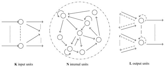
Figure 1.
Architecture of ESN.
Through the [21,22,23], we obtained the method of an ESN for approximating the unknown function. Since any continuous function can be approximated by the results of RNN, this also proves that the existence of an ESN system in the form of (6) such that the inequality is valid for any continuous function on a large enough compact set
where can be any arbitrary positive constant, and the function can be roughly approximated by
where is satisfied by the ideal weight matrix , denotes the ESN approximation error bounded by , where is selected in the sigmoid form provided by
where and are the constant parameters, and is a constant in with . Since the ideal weight matrix W is typically unknown in practice, , an estimation of W is used and updated by creating adaptive laws online to ensure the asymptotic tracking performance.
Remark 1.
Based on the aforementioned descriptions, it is found that the ESN is an alternative functional approximation tool. Despite the fact that the RBFNN is frequently used in articles for approximation, the ESN may be trained with more ease and accuracy than the RBFNN because it does not require altering the weights between both the hidden and input layers.
Lemma 2
([24]). Let be a function vector of the ESN. The center of the receptive field and the input variable are and , respectively. Create a new center , with the input variable being and for an integer, . Then, one has
for the same dimension constant, in which and are indeed the vectors made up of the first k components of and .
Assumption 1
([25]). The underlying inequality
is satisfied by the partial derivative , where and , and are known constants.
Assumption 2
([18]). Positive constants and exist for nonlinear functions and of that kind that for
where is the estimation of x.
Remark 2.
Taking from Assumption 2 results in , proving the existence of strictly rising smooth functions with , which serve as the bounding functions for . Similar to this, strictly growing smooth functions with serving as the bounding functions of are also possible.
Lemma 3
([26]). For , the following inequality holds
where and .
Lemma 4
([19]). For Lemma 1 and state transformation, the following inequality holds
where , and , are positive design parameters.
Lemma 5
([27]). If input noise satisfies , where is the output of the command filtering, the inequality as following is real for a scalar
3. Observer-Based Controller Design and Stability Analysis
A backstepping design process for system (1) using the adaptive neural control protocol is presented in this section.
An ESN-based observer is built to estimate the unknown state of the system (1) as below
where is the estimation of , , , is used to estimate the unknown ideal weight vector, and it estimates . is the to-be-designed observation gain parameter. is the estimation of . is an unidentified nonlinear function, thus an ESN is used to model it in a way that, for a given degree of precision
with is the ideal right vector, and is the approximation error function.
The estimating error is defined as , for .
Using (16) and (17), the error dynamic can be given as
where , , and
Define , and is to address the impact of the on the error dynamic.
Then, (18) can be rewritten as
Choose the Lyapunov function candidate as
with P being the to-be-designed positive definite matrix and the constant will be specified later.
Differentiating can get
According to differential mid-value theorem, one can get
where matrix E is defined as
From Assumption 2 and Lemma 5, we have
where and are positive design constants.
Invoking (22)–(26) into (21), one can obtain
Then, a stabilization control method is proposed for this kind of nonlinear system. The coordinate transformation of z is described by
where and denotes the output of command filtering.
To avoid the increased complexity caused by the backstepping controller design, the command filter is defined as
where is denoted as the output of the command filter that the virtual control signal is the corresponding input signal, and is a positive design parameter. The initial condition is . Since signal noise is ubiquitous, observation and control require real signals, specified frequencies, and sudden changes in interference are excluded or limited as much as possible, so command filters are applied and parameters are set.
To deal with the filtering error z, the error compensation signals for are designed. Define the compensated errors as
Together with (16), (28) and (30), one can differentiate as
Choose the Lyapunov–Krasovskii function candidate as
where is a design constant, and is the estimation of , m is a positive design parameter that will be designed later.
The derivative forms of can be presented as
According to Lemma 3, one has
where is a positive design parameter.
Invoking (34) into (33) yields
Design the compensation signal as
where is a positive design parameter.
Substituting (36) into (35) gives
where
with . For the unknown , an ESN is employed to approximate it and such that for given , , with .
Using Lemmas 2 and 3, the following inequality holds
where being a positive constant, , and .
From (38), (37) can be rewritten as
Develop the virtual control signal and adaptive law as
where is a positive design parameter.
By substituting (40) and (41) into (39), it follows that
Considering (16), (28), (30) and differentiating with respect to time yields
Consider the Lyapunov–Krasovskii function candidate
where is a design constant, and is estimation of .
Invoking (43) and (44), the derivative of is given by
Consider the following fact
where is a positive design parameter.
According to (46), it can be obtained
The compensation signal is designed as
where is a positive design parameter.
Then, (47) can be rewritten in the following form
where
with . Once again, an ESN is used to approximate the unknown function such that for given , , with .
Similar to step 1, one has
with , and .
It follows from substituting (50) into (49) that
Choose the virtual control signal and adaptive law as
where is a positive design parameter.
According to (52) and (53), one has
According to (16), (28), (30), the derivative of is
Construct the Lyapunov–Krasovskii function candidate as
where is a design constant and , . and are estimation of and .
is the time derivative of
according to Lemma 3, one can get
where is a positive design parameter.
By taking (58) into consideration, one arrives at
The compensation signal is proposed as
where is a positive design parameter.
Substituting (60) into (59) yields
Let
with . Similarly to step i, it follows that and .
The following inequality holds
with , and .
From (61) and (62), one has
Design the actual control signal u and the adaptive law as
where , are positive parameters to be designed.
Along with (63)–(67), can be concluded as
Notice that
Consequently, is rewritten as
To develop the adaptive law regarding , the Lyapunov function candidate can be constructed as
with being a positive constant.
Differentiating and taking (70) into account, we have
Choosing
with being a positive constant. Substituting (71) into (70) yields
Therefore, based on the previous discussion, we construct the Lyapunov function and differentiate it, one can obtain
Using Lemmas 3 and 4, one can get
with , , and is a positive design parameter.
Then, (74) can be rewritten as
Theorem 1.
For the system (1) that fulfilling all presumptions construct the observer (16). Assume that ESN can approximate the packaged nonlinear function such that the approximation errors are constrained. If a definite positive matrix P exists, then
where , σ, and are constants and ensure that the closed-loop system is semi-globally stabilized, and by selecting suitable design parameters, it is possible to make any variable in the closed-loop system is infinitely small.
Proof.
Combining (77) and (78) yields
Notice that
Taking (79) and (80) into account gives
For a given constant , a symmetric and positive matrix variable P must exist in order for the error dynamics to be stable. This matrix inequality is
This matrix inequality is challenging to resolve directly since E is a function matrix. Another aspect, Assumption 1 suggests that a function exists, such that
Consequently, matrix E can be written as
where is a square matrix of n-order. Furthermore, according to a convex combination theory, the solvability of (81) is related to that of a collection of matrix inequalities with the following type of time-invariant
where the set is a member of the known matrix C.
It is implied by inequality (78) that there is a constant such that
which implies that
where denotes the maximum eigenvalue of matrix P.
Furthermore, choose the design parameters , , , and , so that
Define
Then, it follows from (81) that
which implies that all the closed-loop signals are bounded.
It can be seen from that if the convergence of the is guaranteed, the error is actually stable. In the following, we will prove that is bounded.
Construct the following Lyapunov function
Derivative of gives
According to Lemma 5, the following inequality is satisfied with choosing suitable parameter satisfying
where . According to Lemma 1, it is proved that is convergent. Since , the errors are stable.
The proof of theorem is thus completed. □
4. Simulation Results
One example is presented to illustrate the viability of the suggested method in this section.
Think about the following numerical example of a nonlinear system, where the system dynamics is described as
To consider the effect of delays, the time-varying delays are given as and . The observer parameters are taken as and .
Choose the initial values and adaptive parameters .
Figure 2, Figure 3, Figure 4 and Figure 5 show the simulation results. Figure 2 shows the correlation curves between the state variable and its corresponding estimate. The reaction of the actual controller u is shown in Figure 3. The paths of the adaptive laws , , and are depicted in Figure 4 and Figure 5, respectively. According to the different points of the results of this paper and others, such as in the design of the controller while considering the observer, time-delay and unknown control gain brought under the influence of the designed controller and adaptive law is more stable. These figures demonstrate that the simulation results support the effectiveness of the suggested control strategy.
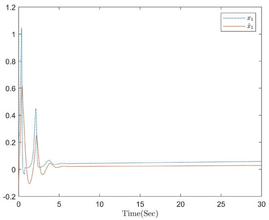
Figure 2.
Paths of state variables and .
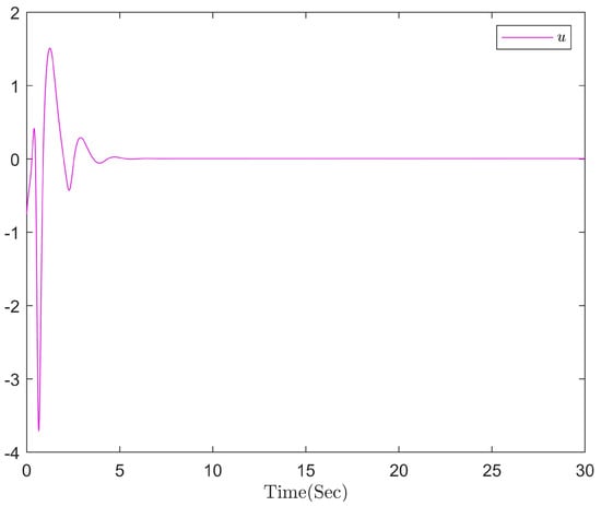
Figure 3.
Curve of the controller u.
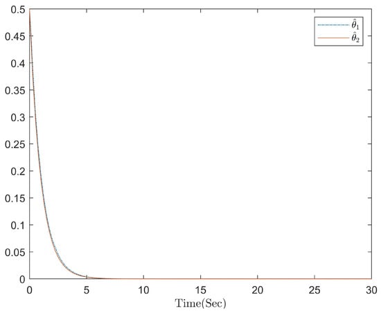
Figure 4.
Curves of adaptive parameters and .
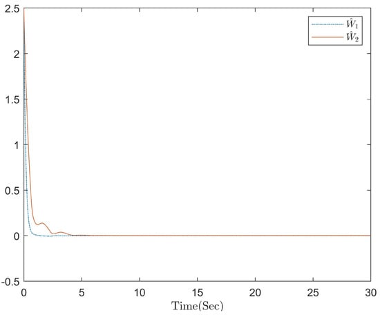
Figure 5.
Curves of adaptive parameters and .
For the observer-based time-delayed system stabilization problem, the initials and estimated values of the system can be observed in the images to reach stability after 5 s, while in this paper it can be clearly seen that the images have stabilized before 5 s.
5. Conclusions
In this paper, a class of adaptive stabilization control problem for nonlinear time-delay systems with unknown control gain is considered. In order to estimate the unmeasurable state variables, a state observer is established. An adaptive stabilization controller based on an ESN observer is proposed by combining the command filtering technique, ESN, and Lyapunov–Krasovskii functionals. On this basis, the unknown function is approximated by an ESN, and the unknown control gain is addressed with the Nussbaum function. Then, the simulation results prove the effectiveness of the designed scheme.
Author Contributions
Conceptualization, X.L.; Methodology, S.L.; Software, S.L. and Z.L.; Validation, X.L.; Formal analysis, M.L.; Investigation, Z.L. and M.L.; Writing—original draft, Z.L.; Writing—review & editing, S.L. All authors have read and agreed to the published version of the manuscript.
Funding
This research received no external funding.
Data Availability Statement
Not applicable.
Conflicts of Interest
The authors declare no conflict of interest.
Abbreviations
The following abbreviations are used in this paper:
| ESN | Echo state network |
| RBFNN | Radial basis function neural network |
| RNNs | Recurrent neural network |
| DSC | Dynamic surface control |
References
- Bekiaris-Liberis, N.; Krstic, M. Stability of predictor-based feedback for nonlinear systems with distributed input delay. Automatica 2016, 70, 195–203. [Google Scholar] [CrossRef]
- Li, H.; Wang, L.; Du, H.; Boulkroune, A. Adaptive fuzzy backstepping tracking control for strict-feedback systems with input delay. IEEE Trans. Fuzzy Syst. 2017, 25, 642–652. [Google Scholar] [CrossRef]
- Chen, W.S.; Wu, J.; Jiao, L.C. State-feedback stabilization for a class of stochastic time-delay nonlinear systems. Int. J. Robust Nonlinear Control. 2012, 22, 1921–1937. [Google Scholar] [CrossRef]
- Yin, S.; Shi, P.; Yang, H.Y. Adaptive tracking control for nonlinear time-varying delay systems with full state constraints and unknown control coefficients. Automatica 2018, 93, 444–453. [Google Scholar]
- Li, F.B.; Shi, P.; Wu, L.G.; Zhang, X. Fuzzy-model-based D-stability and nonfragile control for discrete-time descriptor systems with multiple delays. IEEE Trans. Fuzzy Syst. 2014, 22, 1019–1025. [Google Scholar] [CrossRef]
- Leu, Y.G.; Lee, T.T.; Wang, W.Y. Observer-based adaptive fuzzy- neural control for unknown nonlinear dynamical systems. IEEE Trans. Syst. Man Cybern. 1999, 29, 583–591. [Google Scholar]
- Hua, C.; Guan, X.P.; Shi, P. Robust Output Feedback Tracking Control for Time-Delay Nonlinear Systems Using Neural Network. IEEE Trans. Neural Netw. 2007, 18, 495–505. [Google Scholar] [CrossRef]
- Liu, Y.J.; Tong, S.C.; Wang, D.; Li, T.S.; Chen, C.L.P. Adaptive neural output feedback design with reduced-order observer for a class of uncertain nonlinear SISO systems. IEEE Trans. Neural Netw. 2011, 22, 1328–1334. [Google Scholar]
- Wang, T.; Zhang, Y.F.; Qiu, J.B.; Gao, H.J. Adaptive fuzzy backstepping control for a class of nonlinear systems with sampled and delayed measurements. IEEE Trans. Fuzzy Syst. 2015, 23, 302–312. [Google Scholar] [CrossRef]
- Hua, C.C.; Guan, X.P. Output feedback stabilization for time-delay nonlinear interconnected systems using neural network. IEEE Trans. Neural Netw. 2008, 19, 673–688. [Google Scholar]
- Sakthivel, R.; Manickavalli, S.; Parivallal, A. Observer-based bipartite consensus for uncertain Markovian-jumping multi-agent systems with actuator saturation. Eur. J. Control. 2021, 61, 13–23. [Google Scholar] [CrossRef]
- Nussbaum, R.D. Some remarks on a conjecture in parameter adaptive control. Syst. Control. Lett. 1983, 3, 243–246. [Google Scholar] [CrossRef]
- Ge, S.S.; Hong, F.; Lee, T.H. Adaptive neural control of nonlinear time-delay systems with unknown virtual control coefficients. IEEE Trans. Syst. 2004, 34, 499–516. [Google Scholar] [CrossRef]
- Wang, Y.C.; Zhang, H.G.; Wang, Y.Z. Fuzzy adaptive control of stochastic nonlinear systems with unknown virtual control gain function. ACTA Autom. Sin. 2006, 32, 170–178. [Google Scholar]
- Yu, Z.X.; Li, S.G.; Du, H.B. Razumikhin Nussbaum lemma based adaptive neural control for uncertain stochastic pure-feedback nonlinear systems with time-varying delays. Int. J. Robust Nonlinear Control 2013, 23, 1214–1239. [Google Scholar] [CrossRef]
- Shi, W.X. Observer-based fuzzy adaptive control for multi-input multi-output nonlinear systems with a nonsymmetric control gain matrix and unknown control direction. Fuzzy Sets Syst. 2015, 263, 1–26. [Google Scholar] [CrossRef]
- Emran, B.J.; Najjaran, H. Global tracking control of quadrotor based on adaptive dynamic surface control. Int. J. Dyn. Control 2021, 9, 240–256. [Google Scholar] [CrossRef]
- Yu, J.P.; Shi, P.; Dong, W.J.; Lin, C. Adaptive Fuzzy Control of Nonlinear Systems With Unknown Dead Zones Based on Command Filtering. IEEE Trans. Fuzzy Syst. 2018, 26, 46–55. [Google Scholar] [CrossRef]
- Sun, W.; Wu, Y.Q.; Sun, Z.Y. Command filter-based finite-time adaptive fuzzy control for uncertain nonlinear systems with prescribed performance. IEEE Trans. Fuzzy Syst. 2020, 28, 3161–3170. [Google Scholar] [CrossRef]
- Lin, Z.; Liu, Z.; Zhang, Y.; Chen, C.L.P. Command filtered neural control of multi-agent systems with input quantization and unknown control direction. Neurocomputing 2021, 430, 47–57. [Google Scholar] [CrossRef]
- Xu, D.M.; Lan, J.; Principe, J.C. Direct adaptive control: An echo state network and genetic algorithm approach. In Proceedings of the 2005 IEEE International Joint Conference on Neural Networks, Montreal, QC, Canada, 31 July–4 August 2005. [Google Scholar]
- Hart, A.; Hook, J.; Dawes, J. Embedding and approximation theorems for echo state networks. Neural Netw. 2020, 128, 234–247. [Google Scholar] [CrossRef]
- Chen, Q.; Shi, L.L.; Na, J. Adaptive echo state network control for a class of pure-feedback systems with input and output constraints. Neurocomputing 2018, 274, 1370–1382. [Google Scholar] [CrossRef]
- Chen, B.; Lin, C.; Liu, X.P.; Liu, K.F. Observer-Based Adaptive Fuzzy Control for a Class of Nonlinear Delayed Systems. IEEE Trans. Syst. 2016, 46, 27–36. [Google Scholar] [CrossRef]
- Chen, B.; Zhang, H.G.; Liu, X.P.; Lin, C. Neural Observer and Adaptive Neural Control Design for a Class of Nonlinear Systems. IEEE Trans. Neural Netw. Learn. Syst. 2018, 29, 4261–4271. [Google Scholar] [CrossRef]
- Li, B.M.; Xia, J.W.; Sun, W.; Park, J.H.; Sun, Z.Y. Command filter-based event-triggered adaptive neural network control for uncertain nonlinear time-delay systems. Int. J. Robust Nonlinear Control. 2020, 30, 6363–6382. [Google Scholar] [CrossRef]
- Levant, A. Higher-order sliding modes, differentiation and output-feedback control. Int. J. Control 2010, 76, 924–941. [Google Scholar] [CrossRef]
Disclaimer/Publisher’s Note: The statements, opinions and data contained in all publications are solely those of the individual author(s) and contributor(s) and not of MDPI and/or the editor(s). MDPI and/or the editor(s) disclaim responsibility for any injury to people or property resulting from any ideas, methods, instructions or products referred to in the content. |
© 2023 by the authors. Licensee MDPI, Basel, Switzerland. This article is an open access article distributed under the terms and conditions of the Creative Commons Attribution (CC BY) license (https://creativecommons.org/licenses/by/4.0/).