Article

Position and Attitude Tracking Finite-Time Adaptive Control for a VTOL Aircraft Using Global Fast Terminal Sliding Mode Control

1
Key Laboratory of Electric Drive and Control of Anhui Higher Education Institutes, Anhui Polytechnic University, Wuhu 241000, China
2
Key Laboratory of Advanced Perception and Intelligent Control of High-End Equipment, Ministry of Education, Anhui Polytechnic University, Wuhu 241000, China
*
Author to whom correspondence should be addressed.
Mathematics 2023, 11(12), 2732; https://doi.org/10.3390/math11122732
Submission received: 4 May 2023 / Revised: 7 June 2023 / Accepted: 14 June 2023 / Published: 16 June 2023
(This article belongs to the Special Issue Advances in Complex Systems and Their Control Principles)

Abstract

:
In this work, the position and attitude tracking finite-time adaptive control problem of a type of vertical take-off and landing (VTOL) aircraft system is studied. Here, the dynamic of the VTOL aircraft is subjected to external disturbances and unknown nonlinearities. Firstly, radial basis function neural networks are introduced to approximate these unknown nonlinearities, and adaptive weight update laws are proposed to replace unknown ideal weights. Secondly, for the errors generated in the approximation process and the external disturbances of the aircraft system, adaptive parameter update laws are presented. After that, based on the designed global fast terminal sliding mode control functions and adaptive update laws, we present the position tracking control laws and the roll angle control law. Then, based on this, the adaptive global fast terminal sliding control laws for the given aircraft system are finally obtained. Meanwhile, the stability of the aircraft control system is proven by using Lyapunov stability theory and designed adaptive control laws. It is not only ensured that the outputs of the aircraft system can track the given trajectories, but also ensured that the tracking errors can converge to approximately zero within a finite time. Finally, the validity of the designed adaptive control laws is verified through three numerical examples. It can be obtained that the finite-time tracking problems of the given aircraft system can be achieved at 18.8766 s and 14.6340 s under the given parameters. The results are consistent with the theoretical analysis. In addition, under the control laws proposed in this work, the aircraft system can achieve tracking after 9.443 s and 9.674 s and the tracking errors are basically close to zero, which is significantly superior to other control methods considered in this work.

1. Introduction

During the past decade, vertical take-off and landing (VTOL) aircraft systems have achieved widespread attention because of their simple structures and unrestricted free take-off and landing. They have been widely applied in fields such as military, civil and urban air mobility [1,2,3,4].
At present, for the control problems of VTOL aircraft, many research results have been obtained. In [5], the global configuration stabilization control problem of VTOL aircraft under a strong output coupling was addressed, in which the smooth static feedback control method was used to design the tracking controller. In [6], the authors discussed the fault-tolerant tracking problem of a VTOL aircraft under external disturbances and actuator faults, in which the global convergence of tracking error was obtained via using the proposed robust control scheme. In [7], the tracking control problem of the VTOL aircraft with uncertainties was designed, in which the tracking errors were able to globally achieve ultimately bounded status under the designed fuzzy-based adaptive output feedback control strategy. Moreover, by using the designed tracking controller, the authors of [8,9] solved the output tracking problem of VTOL aircraft with velocity-sensorless and delayed measurement outputs. Through applying the model predictive control method, the trajectory tracking control for the VTOL aircraft was addressed by the authors of [10,11]. Additionally, some control strategies, such as the output feedback tracking control law [12], the adaptive neural network backstepping control law [13], and the robust dynamic surface tracking control law [14], were presented to solve the control problems of planar VTOL aircraft. Furthermore, many scholars have conducted research on the control problems of fixed-wing VTOL and electric VTOL; relevant results have been found in [15,16,17,18,19]. It is worth noting that as a typical underactuated system, designing a good control law is particularly important for the tracking control of VTOL aircraft. This is especially true when the VTOL aircraft system has external disturbances and unknown nonlinear dynamics. This is the first starting point of our work.
In some practical engineering systems, for example, the chemical reaction process [20] and the attitude control of spacecraft [21], stability typically needs to be achieved within a finite time. However, many control methods can only obtain stability of control systems within an infinite time [22,23,24]. Therefore, some researchers have shifted their focus to finite-time control problems [25,26,27]. For instance, the adaptive finite-time consensus control design for a type of multi-agent systems with unknown actuator faults was studied in [28,29]. In [30], the authors designed a neural-based adaptive finite-time controller and applied it to solve the tracking control problem of a class of non-strict feedback systems with multiple constraints. For the tracking control problem of a class of nonlinear systems with the strict-feedback form, the authors of [31] presented a command filtered-based finite-time adaptive output tracking control scheme. Moreover, the authors of [32,33,34] investigated the finite-time tracking control problem of nonlinear systems through applying the designed command filtered-based finite-time control scheme. Therefore, the finite time tracking control for a VTOL aircraft system is worth studying. This is another starting point for this work.
As we know, the sliding mode control method has a good advantage in dealing with nonlinear system problems. Currently, it is used for the design of control strategies for various complex systems and can achieve good control performance [35,36,37,38]. Furthermore, to obtain the finite-time stability of control systems, some researchers also considered the fast terminal sliding mode control (FTSMC) method. Recently, the control laws with FTSMC have been developed and widely applied [39,40,41,42]. However, compared with the traditional linear sliding mode control (LSMC), the FTSMC can not only make the tracking errors of a given system converge to approximately zero within a finite time, but can also eliminate chattering effectively because there is no switching term [39,40,41,42]. In addition, we find that few studies have discussed the finite-time tracking problems of VTOL aircraft under the FTSMC method. This is the third starting point for this work.
Inspired by the above-mentioned analysis, this work investigates the position and attitude tracking finite-time control problems of VTOL aircraft with external disturbances by using a global FTSMC method. To cope with the unknown nonlinear dynamics of VTOL aircraft system, the radial basis function neural networks (RBFNNs) are considered in this work. Moreover, some parameter update laws are proposed to tackle the approximation errors generated in the approximation process and the unknown external disturbances of the aircraft system. Combined with the position tracking errors and attitude tracking error, the global FTSMC functions are designed. Based on the application of the neural network control technique, the designed global FTSMC functions and the designed parameter update laws, the adaptive global FTSMC laws for the VTOL aircraft are presented. Given the nature of the FTSMC method, the tracking errors of given aircraft system can converge to approximately zero within a finite time under the designed adaptive control laws. In the end, the validity of designed adaptive control laws is verified through simulation analysis.
The rest of this work is arranged as follows. In Section 2, the dynamic model of VTOL aircraft is given; the RBFNN and some useful lemmas are also provided. In Section 3, the position and attitude tracking control laws are designed by combining the global FTSMC method with the neural network control technique, and the finite-time stabilization of the VTOL aircraft system is proven by utilizing Lyapunov stability theory. In Section 4, two simulation examples are provided to illustrate the validity of the proposed finite-time control laws. Finally, some brief conclusions are drawn in Section 5.

2. Preliminaries and Problem Statement

2.1. Preliminaries

To approximate the unknown nonlinearities of VTOL aircraft, the RBFNN is considered in this work. For any nonlinear function H N N ( x ) , which can be described as [28]:
H N N ( x ) = W T φ ( x )
where x R n , W = [ w 1 , , w l ] T R l are the input of RBFNN and the weight vector, respectively; l > 1 is the neural network node number; φ ( x ) = [ φ 1 ( x ) , , φ l ( x ) ] T R l and φ i ( x ) represent the Gaussian basis function [28], which is given as
φ i ( x ) = exp ( ( x c i ) T ( x c i ) σ i 2 ) ,   i = 1 , , l
where σ i and c i = [ c i 1 , , c i n ] T represent the width of the Gaussian function, and the center of the basis function, respectively.
In addition,
Lemma 1 
([43]). The nonlinear continuous function F ( x ) is defined over a compact set Ω x R n , then there is an RBFNN ( W * ) T φ ( x )  [43], such that
F ( x ) = ( W * ) T φ ( x ) + ρ ( x )
where ρ ( x ) represents bounded approximation error, and W * stands for the ideal weight vector [43], which is given as
W * : = arg min W R n { sup x Ω x | F ( x ) W T φ ( x ) | }
Moreover, some lemmas are provided as follows.
Remark 1. 
Neural network is widely used in various nonlinear systems because of its ability to approach arbitrary nonlinearity with arbitrary accuracy [2,29,30,43,44]. However, it should be pointed out that the number of nodes is difficult to accurately determine when constructing a neural network. Generally speaking, the approximation accuracy of the neural network will be higher with the increase of the number of nodes, but it will also increase the computational complexity. In order to balance the two, the selection of nodes is mostly based on the trial and error method.
Lemma 2 
([42]). If the global fast terminal sliding mode surface satisfies the following form [42]:
s = x ˙ + a 1 x + a 2 x m / n = 0
where x R stands for state variable, a 1 and a 2 represent positive designed constants, and m > 0 , n > 0 are odd integers and m / n < 1 . Thus, Equation (5) can reach x = 0 within the finite time t r [45], and one has
t r = n a 1 ( n m ) ln [ ( a 1 x ( 0 ) n m n + a 2 ) / a 2 ]
Lemma 3 
([44]). For any η > 0 and κ R , there exists the following inequality [44], that is
0 | κ | κ 2 κ 2 + η 2 η
Lemma 4  
([46]). For any uniformly continuous function ω ( t ) defined on [ 0 , + ) , and 0 + ω ( τ ) d τ exists and is bounded, then it is held that lim t + ω ( t ) = 0 .

2.2. Problem Statement

Assuming the existence of external disturbances and referring to [6], the dynamic model of VTOL aircraft system is described as
M x ¨ = u 1 sin θ + u 2 ε 0 cos θ + D 1 ( t ) M y ¨ = u 1 cos θ + u 2 ε 0 sin θ M g + D 2 ( t ) J θ ¨ = u 2 + D 3 ( t )
where x , y and θ stand for the horizontal position, vertical position, and roll angle of aircraft system, respectively. u 1 and u 2 represent the control inputs and stand for the thrust and the torque, respectively. M is the mass of the aircraft, g represents the gravitational acceleration, J is the motion of inertia on the center of mass, and ε 0 stands for the coupling coefficient between the rolling moment and the lateral force. D 1 ( t ) , D 2 ( t ) and D 3 ( t ) denote the unknown external disturbances, which may involve wind gusts, internal couplings, and so on.
By choosing x 1 = x , x 2 = x ˙ , x 3 = y , x 4 = y ˙ , x 5 = θ and x 6 = θ ˙ , the system (8) can be expressed as
x ˙ 1 = x 2 x ˙ 2 = u 1 sin x 5 M + u 2 ε 0 cos x 5 M + D 1 ( t ) M x ˙ 3 = x 4 x ˙ 4 = u 1 cos x 5 M + u 2 ε 0 sin x 5 M g + D 2 ( t ) M x ˙ 5 = x 6 x ˙ 6 = 1 J u 2 + D 3 ( t ) J
In this work, our control objective is to design the adaptive global FTSMC laws u 1 ( t ) and u 2 ( t ) for the aircraft system (8) such that the position outputs (horizontal position and vertical position) x and y are able to track the desired trajectories x d and y d in the presence of unknown external disturbances, and the tracking errors can converge to approximately zero within a finite time. Meanwhile, the roll angle of VTOL aircraft can also track the given roll angle within a finite time via using the designed roll angle control law.
Assumption 1. 
The unknown external disturbances D i ( t ) , i = 1 , 2 , 3 , are bounded. That is to say, there are unknown constants D i * > 0 that satisfy | D i ( t ) | D i * .
Assumption 2. 
The roll angle  θ always lies in region π / 2 < θ < π / 2 .

3. Main Results

In this section, the RBFNN and global FTSMC method will be considered for the control law design of VTOL aircraft. Furthermore, by applying the designed control laws, the position and attitude tracking control problems can be solved. The entire design procedure includes three parts, and the last part is finite-time stability analysis.

3.1. Horizontal Position Tracking Control Law Design

The horizontal position tracking error is defined as z x = x 1 x d , then the derivative of z x is
z ˙ x = x 2 x ˙ d
Using the subsystem x ˙ 2 = U 1 + F 1 + D 1 ( t ) / M , and the derivative of z ˙ x is further given as
z ¨ x = U 1 + F 1 + D 1 ( t ) M x ¨ d
where U 1 = u 1 sin x 5 / M and F 1 = u 2 ε 0 cos x 5 / M .
Noting the parameters ε 0 and u 2 are unknown, an RBFNN is used to approximate the unknown function F 1 [43], then we obtain
F 1 = ( W 1 * ) T φ 1 ( Z 1 ) + ρ 1 ( Z 1 )
where Z 1 = [ x 5 ] T , ρ 1 ( Z 1 ) represents the approximation error and there is | ρ 1 ( Z 1 ) | ρ ¯ 1 with ρ ¯ 1 > 0 being an unknown constant.
Design a global fast terminal sliding mode function [42], s 1 = z ˙ x + α 1 z x + β 1 z x m 0 / n 0 , where α 1 and β 1 are designed positive constants; m 0 and n 0 are positive odd constants and m 0 / n 0 < 1 . Let λ = m 0 / n 0 , and using (11) and (12), the derivative of s 1 is
s ˙ 1 = z ¨ x + α 1 z ˙ x + β 1 m 0 n 0 z x ( m 0 / n 0 ) 1 z ˙ x = U 1 + ( W 1 * ) T φ 1 ( Z 1 ) + ρ 1 ( Z 1 ) + D 1 ( t ) M + α 1 z ˙ x + β 1 λ z x λ 1 z ˙ x x ¨ d
In view of ρ 1 ( Z 1 ) and D 1 ( t ) being bounded unknown parameters, there exists an unknown positive constant Π 1 such that | ρ 1 ( Z 1 ) + D 1 ( t ) / M | ρ ¯ 1 + D 1 * / M = Π 1 .
Defining the following Lyapunov function candidate as
V 1 = 1 2 s 1 2 + 1 2 γ 1 W ˜ 1 T W ˜ 1 + 1 2 μ 1 Π ˜ 1 2
where W ˜ 1 = W ^ 1 W 1 * and Π ˜ 1 = Π ^ 1 Π 1 , W ^ 1 and Π ^ 1 are the estimations of W 1 * and Π 1 , γ 1 and μ 1 are designed positive constants.
Due to | ρ 1 ( Z 1 ) + D 1 ( t ) / M | Π 1 and applying (13), the time derivative of V 1 is
V ˙ 1 = s 1 s ˙ 1 + 1 γ 1 W ˜ 1 T W ^ ˙ 1 + 1 μ 1 Π ˜ 1 Π ^ ˙ 1 = s 1 ( U 1 + ( W 1 * ) T φ 1 ( Z 1 ) + α 1 z ˙ x + β 1 λ z x λ 1 z ˙ x x ¨ d ) + s 1 ( ρ 1 ( Z 1 ) + D 1 ( t ) M ) + 1 γ 1 W ˜ 1 T W ^ ˙ 1 + 1 μ 1 Π ˜ 1 Π ^ ˙ 1 s 1 ( U 1 + ( W 1 * ) T φ 1 ( Z 1 ) + α 1 z ˙ x + β 1 λ z x λ 1 z ˙ x x ¨ d ) + Π 1 | s 1 | + 1 γ 1 W ˜ 1 T W ^ ˙ 1 + 1 μ 1 Π ˜ 1 Π ^ ˙ 1
According to Lemma 3 [44], we have
Π 1 | s 1 | Π 1 η ( t ) + Π 1 s 1 2 s 1 2 + η ( t ) 2
where η ( t ) is any positive uniformly continuous and bounded function [47], which satisfies
lim t 0 t η ( τ ) d τ η 1 < + ,     | η ˙ ( t ) | η 2 < +
Hence, the horizontal position tracking control law U 1 , parameter update laws W ^ ˙ 1 and Π ^ ˙ 1 are designed as
U 1 = k 1 s 1 k 2 s 1 m 1 / n 1 W ^ 1 T φ 1 ( Z 1 ) Π ^ 1 s 1 s 1 2 + η ( t ) 2 α 1 z ˙ x β 1 λ z x λ 1 z ˙ x + x ¨ d
W ^ ˙ 1 = γ 1 s 1 φ 1 ( Z 1 )
Π ^ ˙ 1 = μ 1 s 1 2 s 1 2 + η ( t ) 2
where k 1 and k 2 are designed positive constants, m 1 and n 1 are positive odd constants and m 1 / n 1 < 1 .
Substituting Equations (16) and (18)–(20) into Equation (15), we obtain
V ˙ 1 k 1 s 1 2 k 2 s 1 ( m 1 + n 1 ) / n 1 + 1 γ 1 W ˜ 1 T ( W ^ ˙ 1 γ 1 s 1 φ 1 ( Z 1 ) ) + 1 μ 1 Π ˜ 1 ( Π ^ ˙ 1 μ 1 s 1 2 s 1 2 + η ( t ) 2 ) + Π 1 η ( t ) k 1 s 1 2 k 2 s 1 ( m 1 + n 1 ) / n 1 + Π 1 η ( t )

3.2. Vertical Position Tracking Control Law Design

The vertical position tracking error is defined as z y = x 3 y d , then the derivative of z y is
z ˙ y = x 4 y ˙ d
Using the subsystem x ˙ 4 = U 2 + F 2 g + D 2 ( t ) / M , and the derivative of z ˙ y is further given as
z ¨ y = U 2 + F 2 + D 2 ( t ) M g y ¨ d
where U 2 = u 1 cos x 5 / M and F 2 = u 2 ε 0 sin x 5 / M .
Note that the parameters ε 0 and u 2 are unknown, an RBFNN is applied to approximate the unknown function F 2 [43], then we have
F 2 = ( W 2 * ) T φ 2 ( Z 2 ) + ρ 2 ( Z 2 )
where Z 2 = [ x 5 ] T , ρ 2 ( Z 2 ) represents the approximation error, and there is | ρ 2 ( Z 2 ) | ρ ¯ 2 with ρ ¯ 2 > 0 being an unknown constant.
Design a global fast terminal sliding mode function [42], s 2 = z ˙ y + α 2 z y + β 2 z y λ , where α 2 and β 2 are designed positive constants, the definition of λ is as in Section 3.1, namely, λ = m 0 / n 0 . Applying Equations (23) and (24), we have the derivative of s 2 as
s ˙ 2 = z ¨ y + α 2 z ˙ y + β 2 λ z y λ 1 z ˙ y = U 2 + ( W 2 * ) T φ 2 ( Z 2 ) + ρ 2 ( Z 2 ) + D 2 ( t ) M + α 2 z ˙ y + β 2 λ z y λ 1 z ˙ y g y ¨ d
In view of ρ 2 ( Z 2 ) and D 2 ( t ) being bounded unknown parameters, there exists an unknown positive constant Π 2 such that | ρ 2 ( Z 2 ) + D 2 ( t ) / M | ρ ¯ 2 + D 2 * / M = Π 2 .
Defining the following Lyapunov function candidate as
V 2 = 1 2 s 2 2 + 1 2 γ 2 W ˜ 2 T W ˜ 2 + 1 2 μ 2 Π ˜ 2 2
where W ˜ 2 = W ^ 2 W 2 * and Π ˜ 2 = Π ^ 2 Π 2 , W ^ 2 and Π ^ 2 are the estimations of W 2 * and Π 2 , γ 2 and μ 2 are designed positive constants.
In view of | ρ 2 ( Z 2 ) + D 2 ( t ) / M | Π 2 and applying Equation (25), the time derivative of V 2 as
V ˙ 2 = s 2 s ˙ 2 + 1 γ 2 W ˜ 2 T W ^ ˙ 2 + 1 μ 2 Π ˜ 2 Π ^ ˙ 2 s 2 ( U 2 + ( W 2 * ) T φ 2 ( Z 2 ) + α 2 z ˙ y + β 2 λ z y λ 1 z ˙ y g y ¨ d ) + s 2 ( ρ 2 ( Z 2 ) + D 2 ( t ) M )       + 1 γ 2 W ˜ 2 T W ^ ˙ 2 + 1 μ 2 Π ˜ 2 Π ^ ˙ 2 s 2 ( U 2 + ( W 2 * ) T φ 2 ( Z 2 ) + α 2 z ˙ y + β 2 λ z y λ 1 z ˙ y g y ¨ d ) + Π 2 | s 2 | + 1 γ 2 W ˜ 2 T W ^ ˙ 2 + 1 μ 2 Π ˜ 2 Π ^ ˙ 2
Using Lemma 3 [44], we have
Π 2 | s 2 | Π 2 η ( t ) + Π 2 s 2 2 s 2 2 + η ( t ) 2
Thus, for the vertical position tracking control law U 2 , parameter update laws W ^ ˙ 2 and Π ^ ˙ 2 can be respectively designed as
U 2 = k 3 s 2 k 4 s 2 m 2 / n 2 W ^ 2 T φ 2 ( Z 2 ) Π ^ 2 s 2 s 2 2 + η ( t ) 2 α 2 z ˙ y β 2 λ z y λ 1 z ˙ y + g + y ¨ d
W ^ ˙ 2 = γ 2 s 2 φ 2 ( Z 2 )
Π ^ ˙ 2 = μ 2 s 2 2 s 2 2 + η ( t ) 2
where k 3 and k 4 are designed positive constants and m 2 and n 2 are positive odd constants and satisfy m 2 / n 2 < 1 .
Substituting Equations (28)–(31) into Equation (27), we get
V ˙ 2 k 3 s 2 2 k 4 s 2 ( m 2 + n 2 ) / n 2 + 1 γ 2 W ˜ 2 T ( W ^ ˙ 2 γ 2 s 2 φ 2 ( Z 2 ) ) + 1 μ 2 Π ˜ 2 ( Π ^ ˙ 2 μ 2 s 2 2 s 2 2 + η ( t ) 2 ) + Π 2 η ( t ) k 3 s 2 2 k 4 s 2 ( m 2 + n 2 ) / n 2 + Π 2 η ( t )
According to the definitions of U 1 and U 2 , the adaptive global FTSMC law u 1 ( t ) is obtained as
u 1 ( t ) = M U 1 2 + U 2 2
Correspondingly, the reference angle θ d for roll angle x 5 ( x 5 = θ ) is given as
θ d = a r c tan ( U 1 U 2 )

3.3. Roll Angle Tracking Control Law Design

Based on the reference roll angle θ d , the roll angle tracking error can be defined as z θ = x 5 θ d , then the derivative of z θ is
z ˙ θ = x 6 θ ˙ d
Using the subsystem x ˙ 6 = U 3 + D 3 ( t ) / J , the derivative of z ˙ θ is further given as
z ¨ θ = U 3 + D 3 ( t ) J θ ¨ d
where U 3 = u 2 / J .
Design a global fast terminal sliding mode function [42] s 3 = z ˙ θ + α 3 z θ + β 3 z θ λ , where α 3 and β 3 are designed positive constants; the definition of λ is the same as in the previous section. Then the derivative of s 3 is
s ˙ 3 = z ¨ θ + α 3 z ˙ θ + β 3 λ z θ λ 1 z ˙ θ = U 3 + D 3 ( t ) J + α 3 z ˙ θ + β 3 λ z θ λ 1 z ˙ θ θ ¨ d
Considering that D 3 ( t ) is a bounded unknown parameter, there exists an unknown positive constant Π 3 such that | D 3 ( t ) / J | D 3 * / J = Π 3 .
Defining the following Lyapunov function candidate as
V 3 = 1 2 s 3 2 + 1 2 μ 3 Π ˜ 3 2
where Π ˜ 3 = Π ^ 3 Π 3 , Π ^ 3 is the estimation of Π 3 and μ 3 is the designed positive constant.
In view of | D 3 ( t ) / J | Π 3 and applying Equation (37), the time derivative of V 3 as
V ˙ 3 = s 3 s ˙ 3 + 1 μ 3 Π ˜ 3 Π ^ ˙ 3 s 3 ( U 3 + α 3 z ˙ θ + β 3 λ z θ λ 1 z ˙ θ θ ¨ d ) + s 3 D 3 ( t ) J + 1 μ 3 Π ˜ 3 Π ^ ˙ 3 s 3 ( U 3 + α 3 z ˙ θ + β 3 λ z θ λ 1 z ˙ θ θ ¨ d ) + Π 3 | s 3 | + 1 μ 3 Π ˜ 3 Π ^ ˙ 3
According to Lemma 3 [44], we have
Π 3 | s 3 | Π 3 η ( t ) + Π 3 s 3 2 s 3 2 + η ( t ) 2
Therefore, the roll angle tracking control law U 3 and the parameter update law Π ^ ˙ 3 are designed as
U 3 = k 5 s 3 k 6 s 3 m 3 / n 3 Π ^ 3 s 3 s 3 2 + η ( t ) 2 α 3 z ˙ θ β 3 λ z θ λ 1 z ˙ θ + θ ¨ d
Π ^ ˙ 3 = μ 3 s 3 2 s 3 2 + η ( t ) 2
where k 5 and k 6 are designed positive constants and m 3 and n 3 are positive odd constants and satisfy m 3 / n 3 < 1 .
Substituting Equations (40)–(42) into Equation (39), we have
V ˙ 3 k 5 s 3 2 k 6 s 3 ( m 3 + n 3 ) / n 3 + 1 μ 3 Π ˜ 3 ( Π ^ ˙ 3 μ 3 s 3 2 s 3 2 + η ( t ) 2 ) + Π 3 η ( t ) k 5 s 3 2 k 6 s 3 ( m 3 + n 3 ) / n 3 + Π 3 η ( t )
Therefore, the adaptive global FTSMC law u 2 ( t ) can be obtained by
u 2 ( t ) = J U 3

3.4. Finite-Time Stability Analysis

Based on the results of the above analysis, we can obtain Theorem 1, which is given as:
Theorem 1. 
Given the VTOL aircraft (1) under Assumptions 1 and 2, the adaptive global FTSMC laws (33) and (44) with parameters update laws (19), (20), (30), (31), and (42) are applied. Then, the horizontal position and vertical position outputs of VTOL aircraft can track the given reference trajectories, and the tracking errors can approach zero within a finite time. Meanwhile, the roll angle of VTOL aircraft can also track the given angle within a finite time.
Proof. 
Defining the Lyapunov function V as
V = 1 2 s 1 2 + 1 2 s 2 2 + 1 2 s 3 2 + 1 2 γ 1 W ˜ 1 T W ˜ 1 + 1 2 γ 2 W ˜ 2 T W ˜ 2 + 1 2 μ 1 Π ˜ 1 2 + 1 2 μ 2 Π ˜ 2 2 + 1 2 μ 3 Π ˜ 3 2
Along with Equations (21), (32) and (43), the derivative of V is given as
V ˙ = s 1 s ˙ 1 + s 2 s ˙ 2 + s 3 s ˙ 3 + 1 γ 1 W ˜ 1 T W ^ ˙ 1 + 1 γ 2 W ˜ 2 T W ^ ˙ 2 + 1 μ 1 Π ˜ 1 Π ^ ˙ 1 + 1 μ 2 Π ˜ 2 Π ^ ˙ 2 + 1 μ 3 Π ˜ 3 Π ^ ˙ 3 k 1 s 1 2 k 3 s 2 2 k 5 s 3 2 k 2 s 1 ( m 1 + n 1 ) / n 1 k 4 s 2 ( m 2 + n 2 ) / n 2 k 6 s 3 ( m 3 + n 3 ) / n 3       + ( Π 1 + Π 2 + Π 3 ) η ( t )
Noting the definitions of m 1 , m 2 , m 3 , n 1 , n 2 and n 3 , it can be seen that m 1 + n 1 , m 2 + n 2 and m 3 + n 3 are even constants. Furthermore, it can be deduced that s 1 ( m 1 + n 1 ) / n 1 0 , s 2 ( m 2 + n 2 ) / n 2 0 and s 3 ( m 3 + n 3 ) / n 3 0 . Hence, the Equation (46) is changed to
V ˙ k 1 s 1 2 k 3 s 2 2 k 5 s 3 2 + ( Π 1 + Π 2 + Π 3 ) η ( t )
Applying Equation (17) and integrating Equation (47) over [ 0 , t ] , we have
0 V ( t ) V ( 0 ) 0 t ( k 1 s 1 2 ( τ ) + k 3 s 2 2 ( τ ) + k 5 s 3 2 ( τ ) ) d τ + ( Π 1 + Π 2 + Π 3 ) 0 t η ( τ ) d τ   V ( 0 ) + ( Π 1 + Π 2 + Π 3 ) η 1
which hints that s 1 , s 2 , s 3 , W ^ 1 , W ^ 2 , Π ^ 1 , Π ^ 2 , and Π ^ 3 are bounded.
Furthermore, we can obtain from Equation (48) that
0 t ƛ i s i 2 ( τ ) d τ C 0
where ƛ 1 = k 1 , ƛ 2 = k 3 , ƛ 3 = k 5 , and C 0 = V ( 0 ) + ( Π 1 + Π 2 + Π 3 ) η 1 is a bounded constant.
By utilizing Lemma 4, we can conclude from Equation (49) that
lim t + s 1 = 0
lim t + s 2 = 0
lim t + s 3 = 0
On the one hand, according to the definitions of s 1 , s 2 and s 3 , we have
lim t + z x = lim t + ( x x d ) = 0
lim t + z y = lim t + ( y y d ) = 0
lim t + z θ = lim t + ( θ θ d ) = 0
From Equations (53)–(55), it can be found that the tracking errors z x , z y , and z θ can be close to zero.
On the other hand, applying Lemma 2 [45], we obtain
t r x = n 0 α 1 ( n 0 m 0 ) ln [ α 1 z x ( 0 ) ( n 0 m 0 ) / n 0 + β 1 β 1 ]
t r y = n 0 α 2 ( n 0 m 0 ) ln [ α 2 z y ( 0 ) ( n 0 m 0 ) / n 0 + β 2 β 2 ]
t r θ = n 0 α 3 ( n 0 m 0 ) ln [ α 3 z θ ( 0 ) ( n 0 m 0 ) / n 0 + β 3 β 3 ]
where t r x , t r y , and t r θ represent the reach time when tracking errors z x , z y and z θ converge to zero.
Hence, using Equations (53)–(58), by adjusting the values of m 0 , n 0 , α 1 , β 1 , α 2 , β 2 , α 3 and β 3 , the tracking errors z x , z y and z θ can be close to zero within a finite time. This completes the proof. □
Remark 2. 
Using Equations (56)–(58), we can adjust the reach times t r x , t r y and t r θ by adjusting the values of m0, n0, αi and βi, i = 1,2,3. However, it should be noted that changes in αi and β i also result in changes in the control laws U1, U2 and U3, which in turn affect the amplitude of control inputs u1 (t) and u2(t). Therefore, when selecting these design parameters, we should make appropriate trade-offs between them.
Remark 3. 
Due to the fact that the VTOL aircraft system (9) is an underactuated system with three degrees of freedom and two control inputs, it is impossible to track all three degrees of freedom. As a result, this paper uses (34) to generate the reference trajectory θd for the roll angle.

4. Simulation Analysis

In this section, two simulation examples are provided to illustrate the effectiveness of proposed adaptive global FTSMC laws.
Considering the VTOL aircraft system (8), the parameters are set as: M = 3.0   kg , ε 0 = 0.5 , g = 9.8   m / s 2 , J = 0.5   kg   m 2 , and D 1 ( t ) = D 2 ( t ) = D 3 ( t ) = 0.01 sin ( t ) . The initial states of the VTOL aircraft are given as [ x ( 0 ) , x ˙ ( 0 ) , y ( 0 ) , y ˙ ( 0 ) , θ ( 0 ) , θ ˙ ( 0 ) ] T = [ 1.5 , 0.0 , 0.5 , 0.0 , 0.0 , 0.0 ] T . The reference trajectories are chosen as x d = sin ( 1.5 t ) + sin ( t ) and y d = cos ( 1.5 t ) + cos ( t ) . The simulation time is set as t = 40   s .
For the unknown nonlinear functions F 1 and F 2 with the input being x 5 , the number of nodes of each RBFNN is chosen as l = 7 , the center of the Gaussian function is chosen as [ 4 , 3 , 2 , 0 , 2 , 3 , 4 ] , and the width is set as σ i = 25 for i = 1 , , 7 .
Example 1. 
Considering the control laws (18), (29) and (41), and parameters update laws (19), (20), (30), (31), and (42), the parameters are set as m 0 = 5 , n 0 = 9 , k 1 = k 3 = k 5 = 0.001 , k 2 = 1.2 , k 4 = 8.5 , k 6 = 5.0 , α 1 = α 2 = α 3 = 0.2 , β 1 = β 2 = β 3 = 0.055 , γ 1 = γ 2 = 1.95 , μ 1 = μ 2 = 3.8 , μ 3 = 5.3 , m 1 = m 2 = m 3 = 49 , n 1 = n 2 = n 3 = 53 , and η ( t ) = 10 exp ( 0.01 t ) . The initial states W ^ 1 ( 0 ) = W ^ 2 ( 0 ) = [ 0.01 ] 7 × 1 T and Π ^ 1 ( 0 ) = Π ^ 2 ( 0 ) = Π ^ 3 ( 0 ) = 0.01 are chosen.
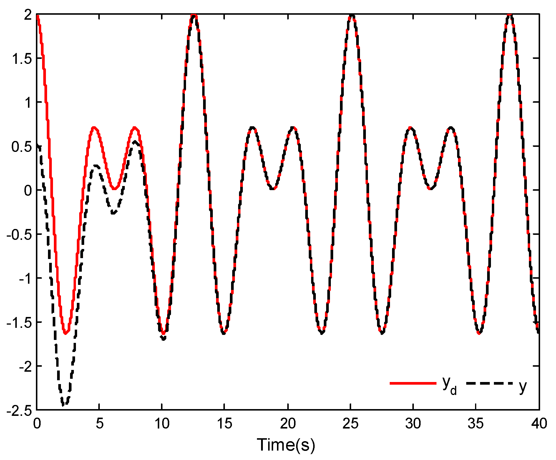
The simulation results are shown in Figure 1, Figure 2, Figure 3, Figure 4, Figure 5, Figure 6 and Figure 7.
The tracking performance curves of the horizontal position, vertical position and roll angle are shown in Figure 1, Figure 2 and Figure 3, respectively. It is seen from these figures that the desired tracking problem of the given VTOL aircraft is solved under the presented adaptive global FTSMC laws. Although the roll angle shown in Figure 3 exhibits significant overshoot at some points, it does not affect the position tracking results of the aircraft.
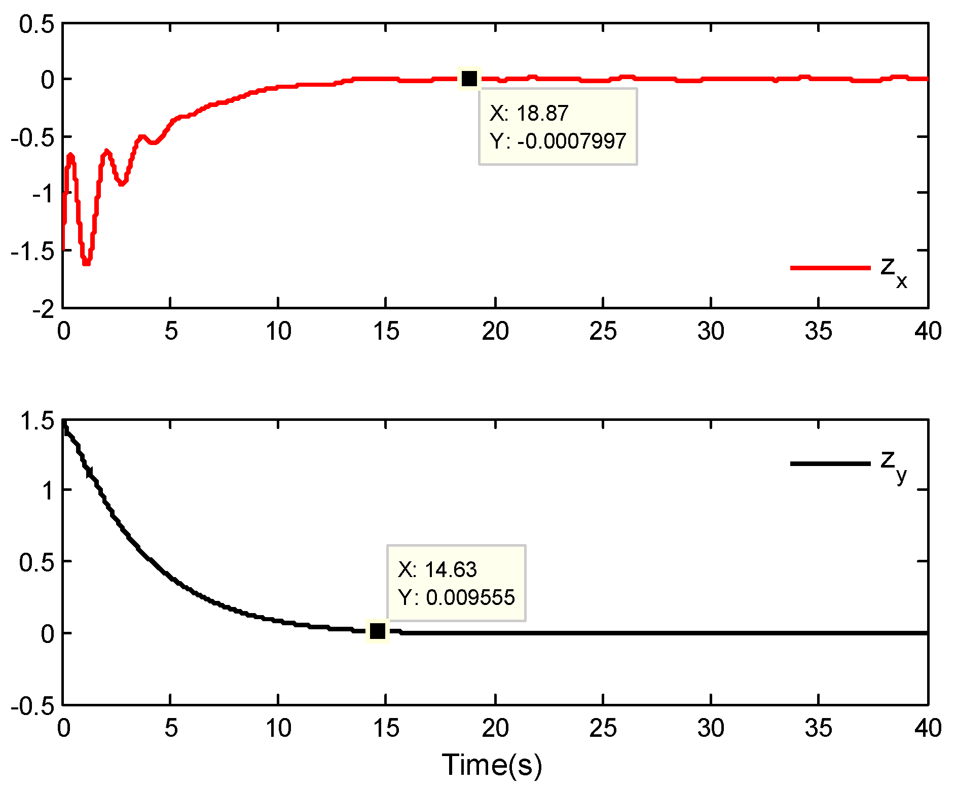
The tracking error curves of the horizontal position and vertical position are described in Figure 4. We can see from Figure 4 that the tracking errors are basically close to zero after a finite time. Noting Equations (53) and (54), it is easy to calculate t r x = 18 . 8766 and t r y = 14 . 6340 by substituting the initial values selected in this example. That is to say, theoretical calculation indicates that the reach times for the horizontal position tracking error and vertical position tracking error close to zero are 18.8766 s and 14.6340 s, respectively. In Figure 3, the tracking errors of the horizontal position and vertical position corresponding to these two times are 7.997 × 10 4 and 9.555 × 10 3 , respectively. From this, it can be concluded that the position tracking errors of the VTOL aircraft system can converge to approximately zero within a finite time, which further indicates the validity of the theoretical analysis.
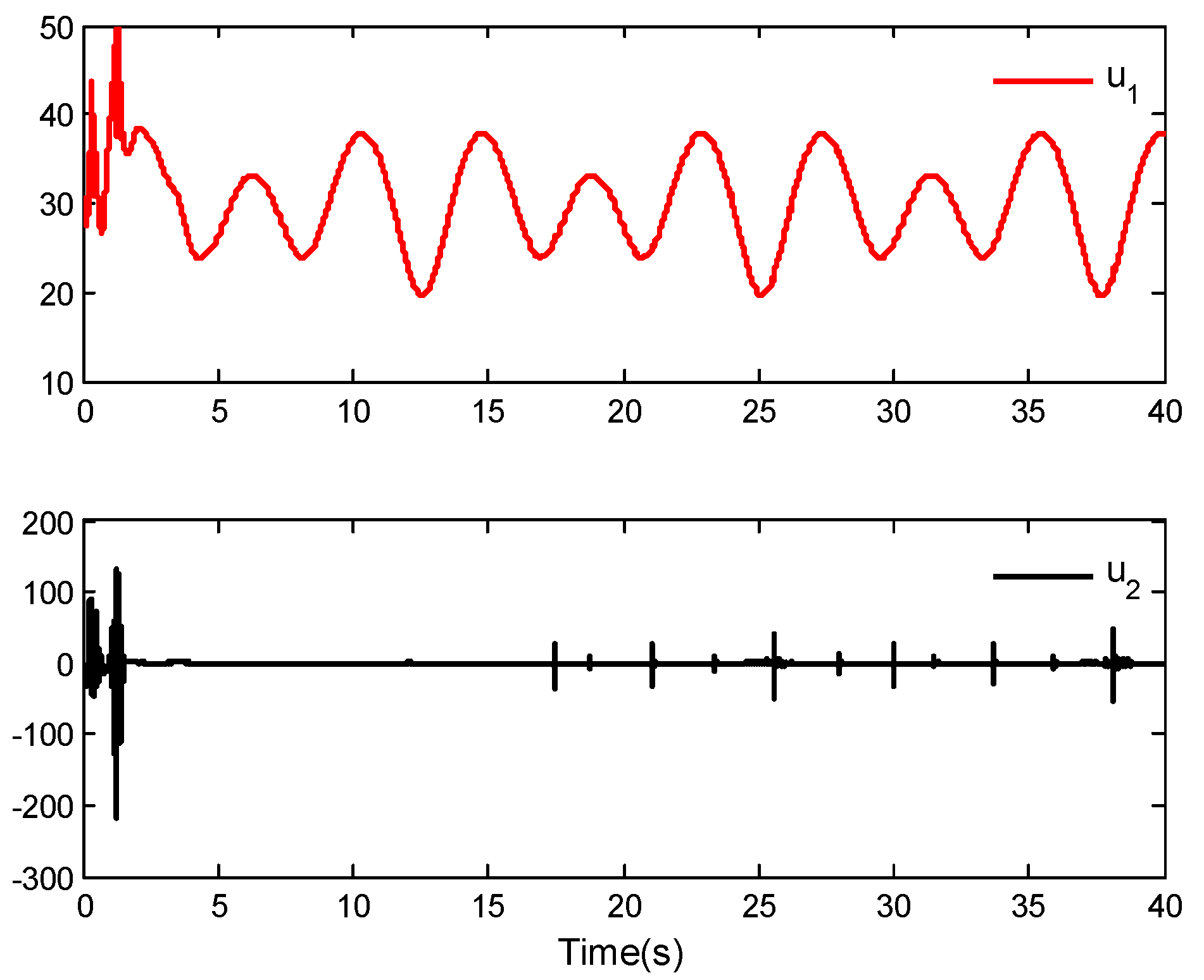
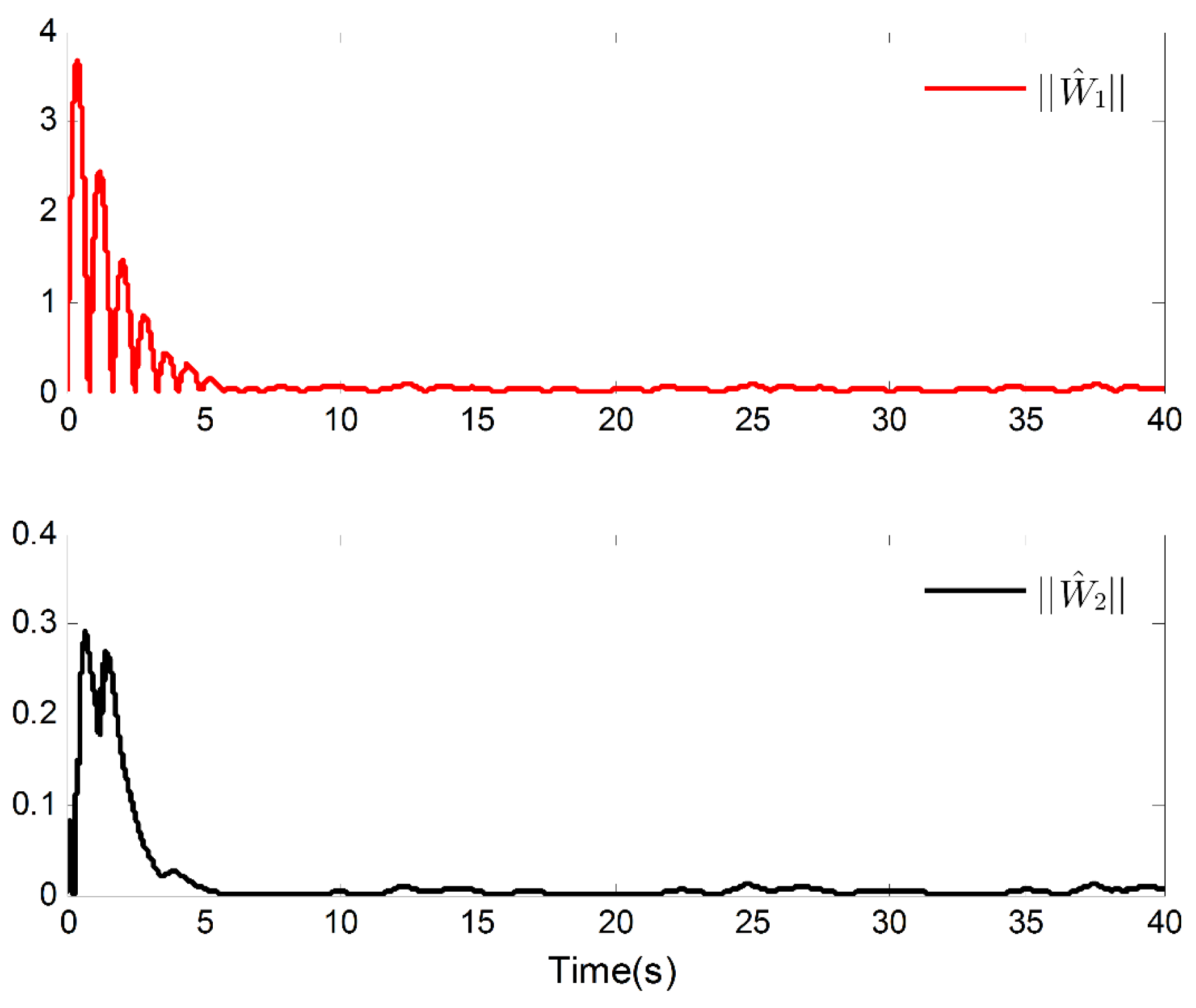
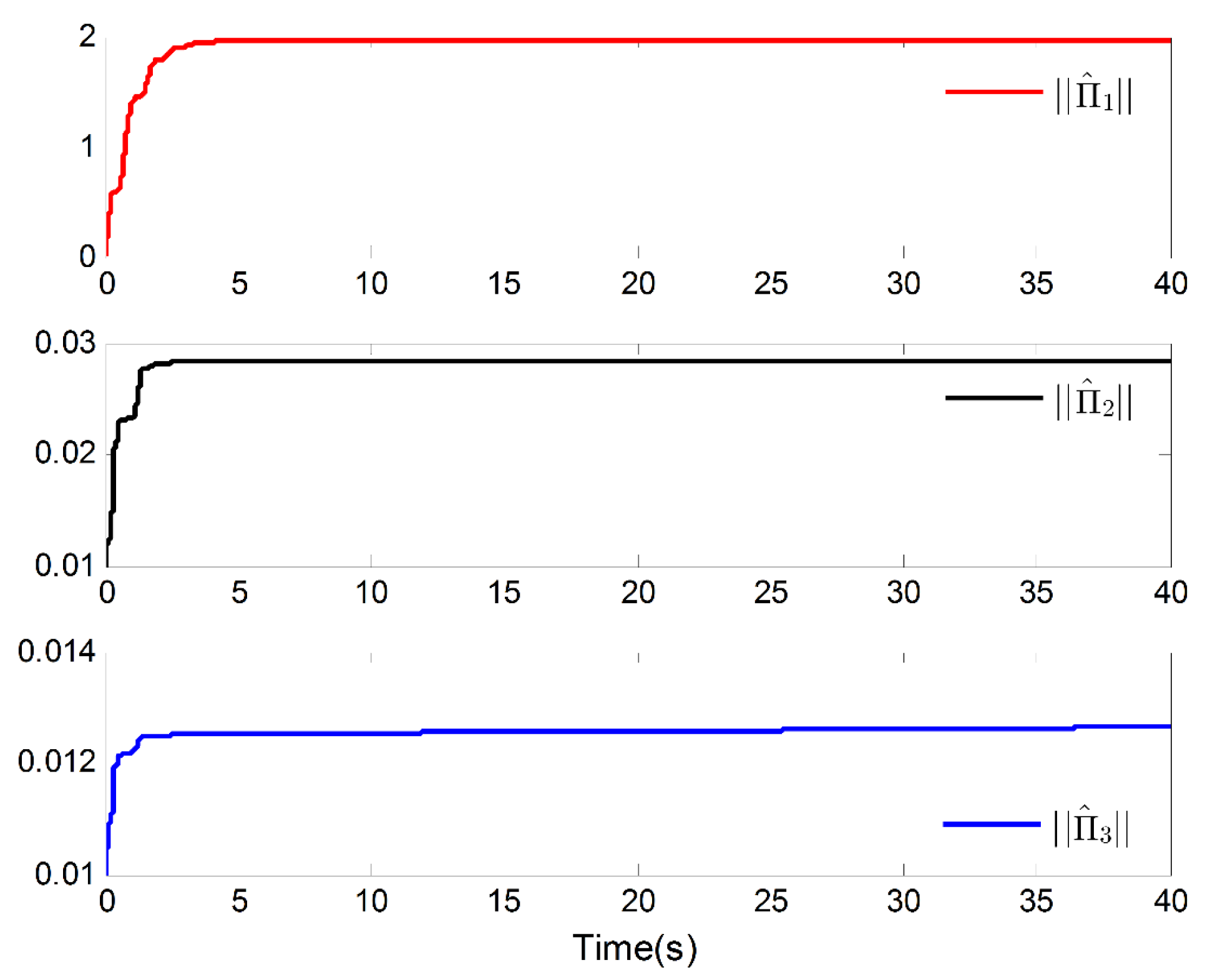
Figure 5 gives the curves of control inputs u 1 ( t ) and u 2 ( t ) , and the curves of parameter update laws W ^ 1 and W ^ 2 , Π ^ 1 , Π ^ 2 and Π ^ 3 are shown in Figure 6 and Figure 7, respectively. It is not difficult to see from these figures that these signals are bounded. This also proves the effectiveness of the proposed control laws from another perspective.
Example 2. 
In this example, the control laws based on the general linear sliding mode control are considered to compare the proposed control laws in this paper. Please refer to Appendix A for a detailed control laws design process. Hence, we have the following control laws and parameter update laws:
U 1 = k 1 s 1 W ^ 1 T φ 1 ( Z 1 ) Π ^ 1 s 1 s 1 2 + η ( t ) 2 α 1 z ˙ x + x ¨ d
W ^ ˙ 1 = γ 1 s 1 φ 1 ( Z 1 )
Π ^ ˙ 1 = μ 1 s 1 2 s 1 2 + η ( t ) 2
U 2 = k 3 s 2 W ^ 2 T φ 2 ( Z 2 ) Π ^ 2 s 2 s 2 2 + η ( t ) 2 α 2 z ˙ y + g + y ¨ d
W ^ ˙ 2 = γ 2 s 2 φ 2 ( Z 2 )
Π ^ ˙ 2 = μ 2 s 2 2 s 2 2 + η ( t ) 2
U 3 = k 5 s 3 Π ^ 3 s 3 s 3 2 + η ( t ) 2 α 3 z ˙ θ + θ ¨ d
Π ^ ˙ 3 = μ 3 s 3 2 s 3 2 + η ( t ) 2
u 1 ( t ) = M ( U 1 ) 2 + ( U 2 ) 2
u 2 ( t ) = J U 3
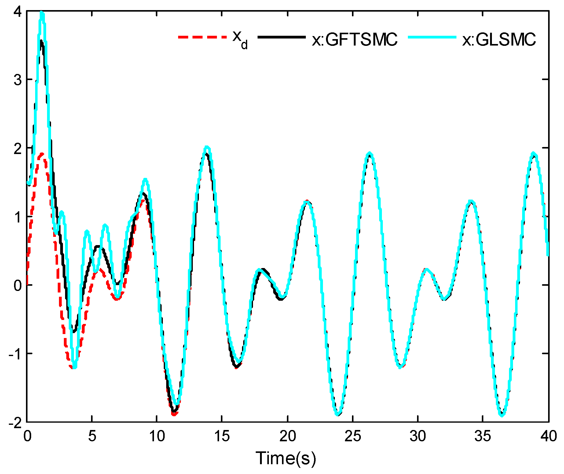
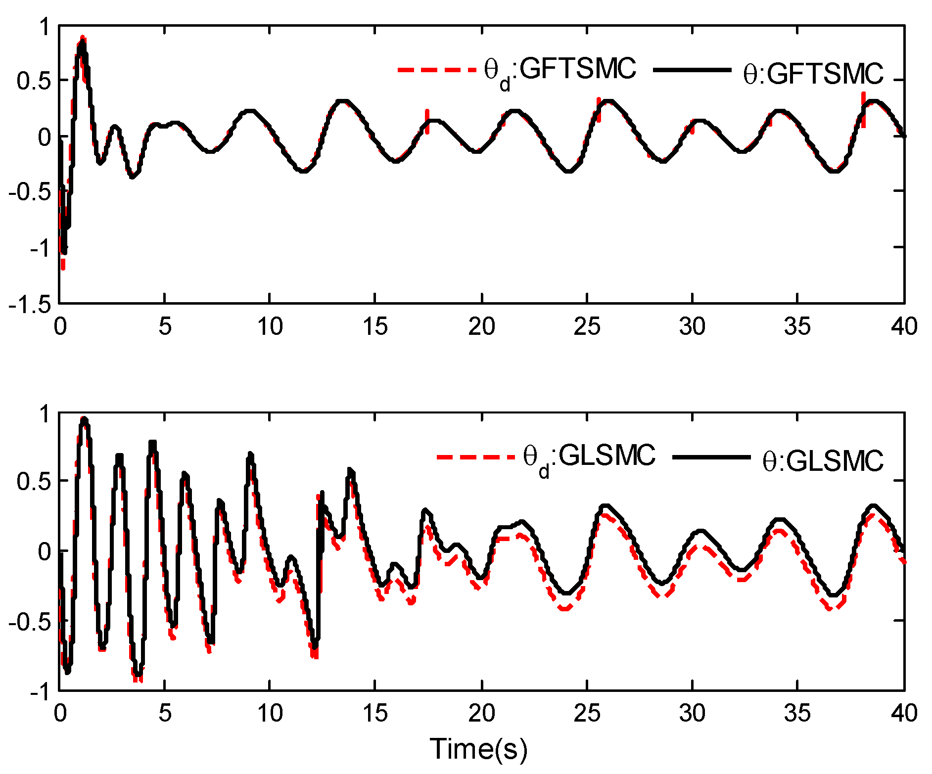
Similar to the analysis in Section 3, it is easy to prove that the horizontal position, vertical position and roll angle outputs of VTOL aircraft can track the reference trajectories. The selection of parameters in Equations (59)–(68) is the same as in Example 1. In this example, GFTSMC stands for the global fast terminal sliding mode control, and GLSMC stands for the general linear sliding mode control.
The comparison results are shown in Figure 8, Figure 9 and Figure 10.
From Figure 8, Figure 9 and Figure 10, it can be found that the tracking control problem of the given VTOL aircraft system can be solved under the designed control laws with general LSMC. However, compared to the control laws with global FTSMC, the overshoot, the adjustment time and the convergence time are all relatively large under the control laws with general LSMC. Specifically, the roll angle tracking error is much larger than under the control laws with FTSMC. In addition, it can be seen that the aircraft system can achieve tracking after 9.443 s and the tracking errors can basically converge to zero by using the control laws proposed in this work. That is to say, under the same parameter selection, the control performance obtained by the control laws with global FTSMC is better than that obtained by the control laws with general LSMC. These results further elucidate the validity of the control laws proposed in this work.
Example 3. 
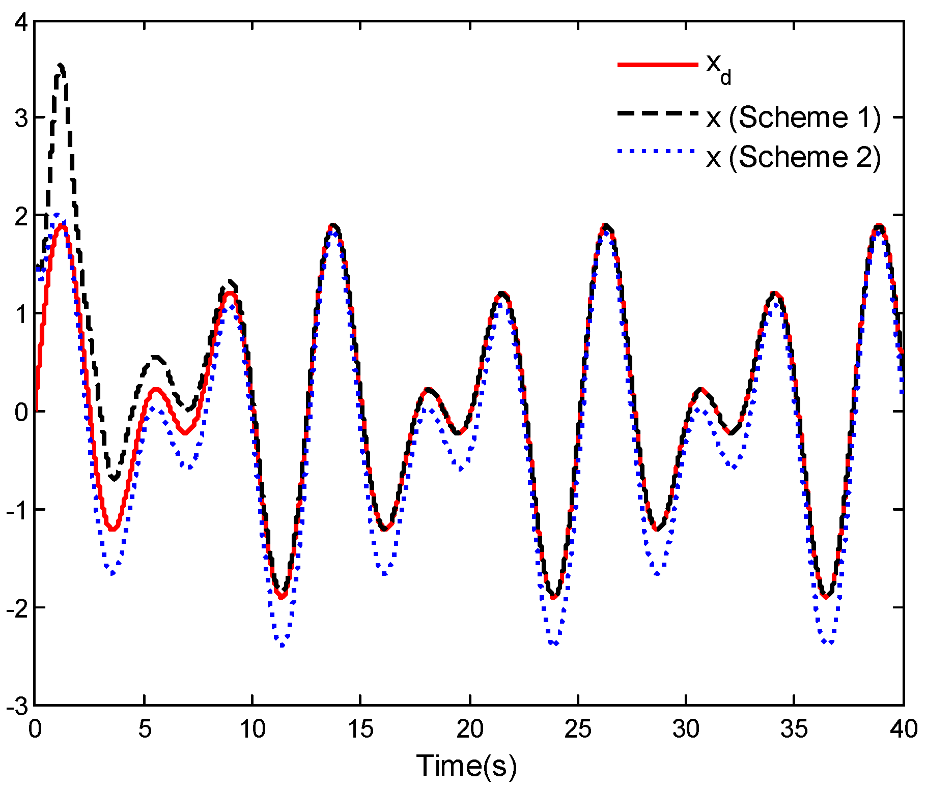
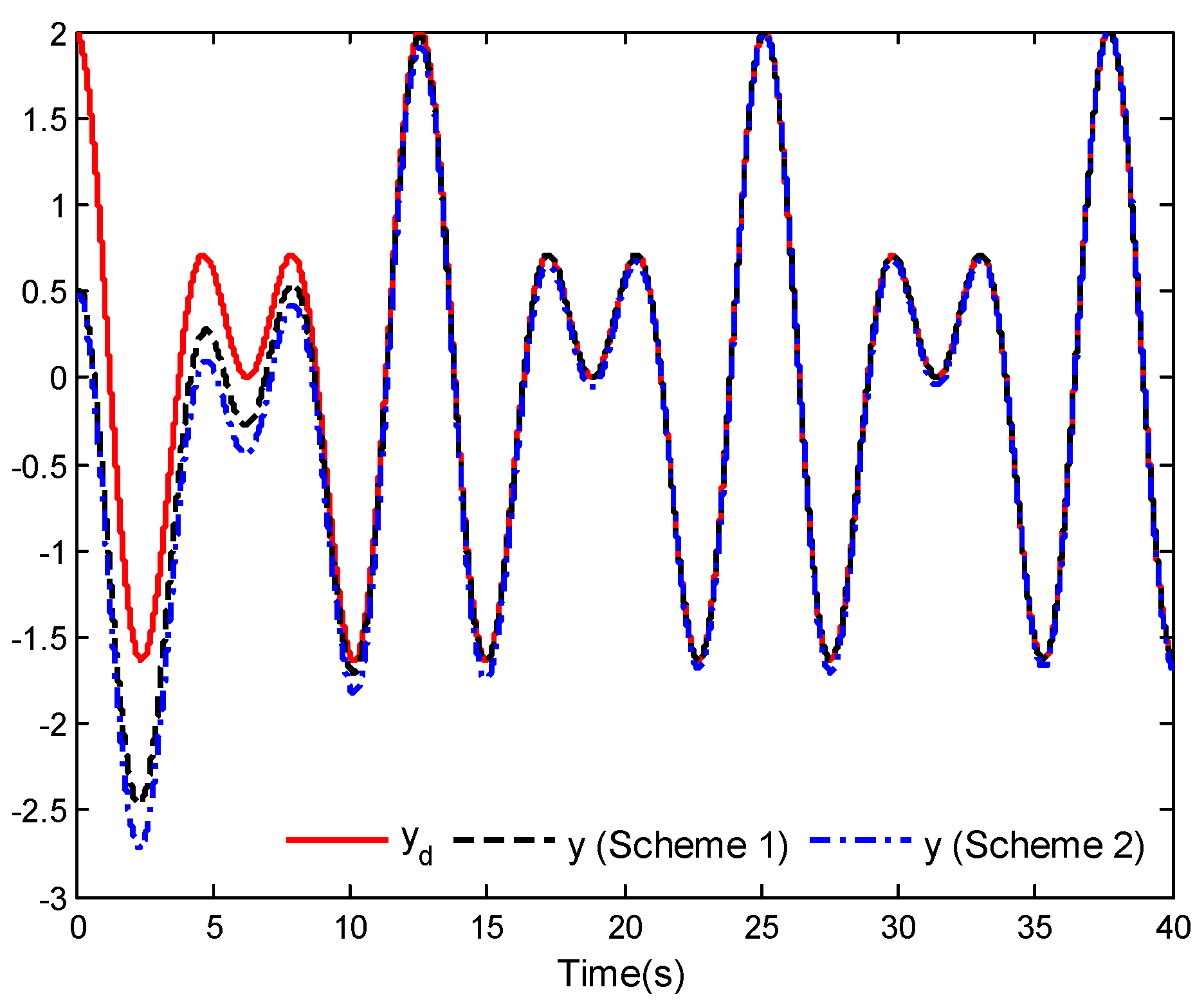
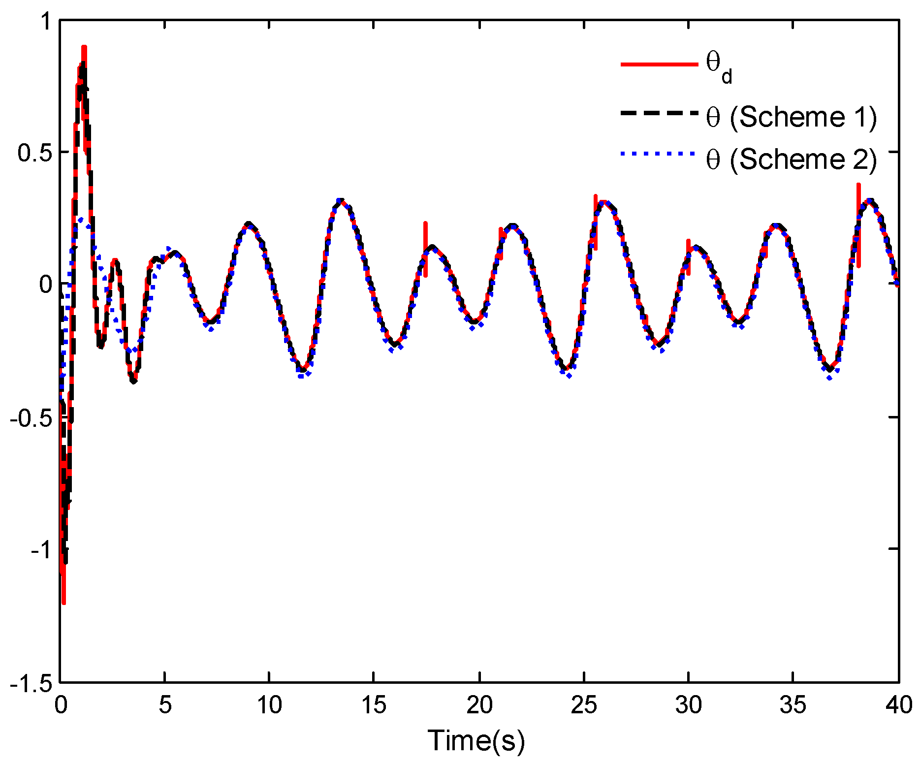
This example further illustrates the effectiveness of the control law proposed in this work. In this example, the control laws (Scheme 1) proposed in this work are compared and analyzed with the control laws (Scheme 2) proposed in [5]. The selection of parameters should be consistent with Example 1. The simulation results are given in Figure 11, Figure 12 and Figure 13.
By applying Scheme 1 and Scheme 2, the comparison results of the horizontal position tracking performance and the vertical position tracking performance are given in Figure 11 and Figure 12. It is easy to see from the two figures that the tracking control of the considered VTOL aircraft is achievable. In addition, the aircraft system can achieve tracking after 9.443 s and the tracking errors can basically converge to zero by using Scheme 1, which is significantly superior to the Scheme 2. The roll angle tracking performance is shown in Figure 13. From the figure, the given roll angle and the roll angle of VTOL aircraft obtained in Scheme 1 are smoother and have smaller tracking error than those obtained in Scheme 2. Through this example, the validity of control laws presented in this work is further elucidated.
Remark 4. 
In Equation (41), it is necessary to use the first-order and second-order derivatives of a given roll angle θ d to design the roll angle tracking control law U 3 . However, the process of obtaining θ ˙ d and θ ¨ d is very complex. With reference to [48], a third-order integral-chain differentiator is considered in our simulation examples, which is described as
{ X ˙ 1 = X 2 X ˙ 2 = X 3 X ˙ 3 = ϑ 1 π 3 ( X 1 θ d ) ϑ 2 π 2 X 2 ϑ 3 π X 3
where the outputs X 2 and X 3 stand for θ ˙ d and θ ¨ d , respectively. In simulation examples, we take ϑ 1 = 10 , ϑ 2 = 30 , ϑ 3 = 30 , π = 1 / [ 100 ( 1 exp ( 2.5 t ) ) ] as 0 t 1.0   s , and π = 0.01 as t > 1.0   s .
Remark 5. 
In Example 2, to better compare the effectiveness of the two types of control laws, the parameter selection is kept the same as in Example 1. In this case, we obtained the simulation results of Figure 8, Figure 9 and Figure 10. It should be noted that in Example 2, we can also adjust relevant parameters to achieve better control performances for the VTOL aircraft system under the control laws with general linear sliding mode control. By using the control laws designed in this work, the desired tracking problems can be achieved within a finite time and with better tracking performance. However, in order to obtain smaller control law amplitude, significant errors may occur at the beginning of the simulation. Therefore, we need to make appropriate trade-offs between the two.

5. Conclusions

This work mainly discussed the application of a global FTSMC method in the position and attitude tracking finite-time control problem of the VTOL aircraft. The RBFNNs were applied to approximate the unknown nonlinear terms of VTOL aircraft, and some parameter update laws were presented in the analysis process. Meanwhile, the global FTSMC functions were designed via utilizing the position tracking errors and attitude tracking error. Then, the adaptive global FTSMC laws were designed by using the neural network control method, the global FTSMC functions and the designed parameter update laws. Based on the proposed adaptive global FTSMC laws, the simulation results proved that the position and attitude outputs of the VTOL aircraft system can track the desired trajectories and the tracking errors can be close to zero within a finite time. In Example 1, it can be seen that the finite-time tracking problems can be achieved at 18.8766 s and 14.6340 s. The results of this example were consistent with the theoretical analysis results. Moreover, in Examples 2 and 3, the aircraft system can achieve tracking after 9.443 s and 9.674 s, and the tracking errors can basically converge to zero by using the control laws proposed in this work. These results are significantly superior to other control methods considered in this work.
In this work, the authors mainly focused on the finite-time tracking control for a VTOL aircraft with global FTSMC method. Their potential application areas can include urban air mobility, military, and traffic condition detection. However, the tracking control problem of VTOL aircraft achieving the desired target tracking within a predefined time or fixed time under the global FTSMC method has not been considered. Therefore, the predefined time or the fixed-time tracking control problem of a VTOL aircraft with the global FTSMC method will be studied in future research.
In addition, this work still has certain limitations. For example, the motion model of the given VTOL aircraft does not include a mathematical model of the rotor and the electric motor, nor does it consider actuator faults or time delays of control inputs. If these conditions are considered, can the control proposed in this work still achieve good control performance? Therefore, we will gradually address these concerns in future work.

Author Contributions

Conceptualization, Y.H.; Methodology, X.D.; Software, X.D., Y.H., B.X. and L.T.; Validation, B.X.; Formal analysis, Y.H. and B.X.; Investigation, X.D., Y.H. and L.T.; Resources, Y.H. and L.T.; Data curation, X.D., B.X. and L.T.; Writing—original draft, X.D.; Writing—review & editing, X.D., Y.H., B.X. and L.T.; Project administration, B.X. and L.T.; Funding acquisition, X.D., Y.H., B.X. and L.T. All authors have read and agreed to the published version of the manuscript.

Funding

This work was partially supported by the National Natural Science Foundation of China under Grant 62203011, the Natural Science Foundation of Anhui Province under Grant 2108085MF220, the Pre-research Project of National Natural Science Foundation of Anhui Polytechnic University under Grant Xjky2022042, the Scientific Research Foundation for Introduced Talent Scholars of Anhui Polytechnic University under Grant 2020YQQ041, the Opening Project of Automotive New Technique of Anhui Province Engineering Technology Research Center under Grant QCKJ202207B, and the Program for the Top Talents of Anhui Polytechnic University.

Data Availability Statement

Not applicable.

Conflicts of Interest

The authors declare no conflict of interest.

Appendix A

Considering the general linear sliding mode functions, the control laws design process is shown as follows.
For the horizontal position tracking, design a linear sliding mode function s 1 = z ˙ x + α 1 z x , where α 1 is designed positive constant. Using Equations (10)–(12), the derivative of s 1 is
s ˙ 1 = z ¨ x + α 1 z ˙ x = U 1 + ( W 1 * ) T φ 1 ( Z 1 ) + ρ 1 ( Z 1 ) + D 1 ( t ) M + α 1 z ˙ x x ¨ d
In view of ρ 1 ( Z 1 ) and D 1 ( t ) being bounded unknown parameters, there exists an unknown positive constant Π 1 such that | ρ 1 ( Z 1 ) + D 1 ( t ) / M | ρ ¯ 1 + D 1 * / M = Π 1 .
Defining the following Lyapunov function candidate as
V 1 = 1 2 s 1 2 + 1 2 γ 1 W ˜ 1 T W ˜ 1 + 1 2 μ 1 Π ˜ 1 2
where W ˜ 1 = W ^ 1 W 1 * and Π ˜ 1 = Π ^ 1 Π 1 , W ^ 1 and Π ^ 1 are the estimations of W 1 * and Π 1 , and μ 1 are designed positive constants. Due to | ρ 1 ( Z 1 ) + D 1 ( t ) / M | Π 1 and applying Equation (A1), the time derivative of V 1 is
V ˙ 1 = s 1 s ˙ 1 + 1 γ 1 W ˜ 1 T W ^ ˙ 1 + 1 μ 1 Π ˜ 1 Π ^ ˙ 1 s 1 ( U 1 + ( W 1 * ) T φ 1 ( Z 1 ) + α 1 z ˙ x x ¨ d ) + Π 1 | s 1 | + 1 γ 1 W ˜ 1 T W ^ ˙ 1 + 1 μ 1 Π ˜ 1 Π ^ ˙ 1
According to Lemma 3, we have
Π 1 | s 1 | Π 1 η ( t ) + Π 1 s 1 2 s 1 2 + η ( t ) 2
Hence, the horizontal position tracking control law U 1 , parameter update laws W ^ ˙ 1 and Π ^ ˙ 1 are designed as
U 1 = k 1 s 1 k 2 s 1 m 1 / n 1 W ^ 1 T φ 1 ( Z 1 ) Π ^ 1 s 1 s 1 2 + η ( t ) 2 α 1 z ˙ x + x ¨ d
W ^ ˙ 1 = γ 1 s 1 φ 1 ( Z 1 )
Π ^ ˙ 1 = μ 1 s 1 2 s 1 2 + η ( t ) 2
where k 1 and k 2 are designed positive constants, m 1 and n 1 are positive odd constants and m 1 / n 1 < 1 .
Substituting Equations (A4)–(A7) into Equation (A3), we obtain
V ˙ 1 k 1 s 1 2 k 2 s 1 ( m 1 + n 1 ) / n 1 + 1 γ 1 W ˜ 1 T ( W ^ ˙ 1 γ 1 s 1 φ 1 ( Z 1 ) ) + 1 μ 1 Π ˜ 1 ( Π ^ ˙ 1 μ 1 s 1 2 s 1 2 + η ( t ) 2 ) + Π 1 η ( t ) k 1 s 1 2 k 2 s 1 ( m 1 + n 1 ) / n 1 + Π 1 η ( t )
For the vertical position tracking, design a linear sliding mode function s 2 = z ˙ y + α 2 z y , where α 2 is designed positive constant. Applying Equations (22)–(24), we have the derivative of s 2 as
s ˙ 2 = z ¨ y + α 2 z ˙ y = U 2 + ( W 2 * ) T φ 2 ( Z 2 ) + ρ 2 ( Z 2 ) + D 2 ( t ) M + α 2 z ˙ y g y ¨ d
In view of ρ 2 ( Z 2 ) and D 2 ( t ) being bounded unknown parameters, there exists an unknown positive constant Π 2 such that | ρ 2 ( Z 2 ) + D 2 ( t ) / M | ρ ¯ 2 + D 2 * / M = Π 2 .
Defining the following Lyapunov function candidate as
V 2 = 1 2 s 2 2 + 1 2 γ 2 W ˜ 2 T W ˜ 2 + 1 2 μ 2 Π ˜ 2 2
where W ˜ 2 = W ^ 2 W 2 * and Π ˜ 2 = Π ^ 2 Π 2 , W ^ 2 and Π ^ 2 are the estimations of W 2 * and Π 2 , γ 2 and μ 2 are designed positive constants.
In view of | ρ 2 ( Z 2 ) + D 2 ( t ) / M | Π 2 and applying Equation (A9), the time derivative of V 2 as
V ˙ 2 = s 2 s ˙ 2 + 1 γ 2 W ˜ 2 T W ^ ˙ 2 + 1 μ 2 Π ˜ 2 Π ^ ˙ 2 s 2 ( U 2 + ( W 2 * ) T φ 2 ( Z 2 ) + α 2 z ˙ y g y ¨ d ) + Π 2 | s 2 | + 1 γ 2 W ˜ 2 T W ^ ˙ 2 + 1 μ 2 Π ˜ 2 Π ^ ˙ 2
Using Lemma 3, we have
Π 2 | s 2 | Π 2 η ( t ) + Π 2 s 2 2 s 2 2 + η ( t ) 2
Thus, for the vertical position tracking control law U 2 , parameter update laws W ^ ˙ 2 and Π ^ ˙ 2 can be respectively designed as
U 2 = k 3 s 2 k 4 s 2 m 2 / n 2 W ^ 2 T φ 2 ( Z 2 ) Π ^ 2 s 2 s 2 2 + η ( t ) 2 α 2 z ˙ y + g + y ¨ d
W ^ ˙ 2 = γ 2 s 2 φ 2 ( Z 2 )
Π ^ ˙ 2 = μ 2 s 2 2 s 2 2 + η ( t ) 2
where k 3 and k 4 are designed positive constants and m 2 and n 2 are positive odd constants and satisfy m 2 / n 2 < 1 .
Substituting Equations (A12)–(A15) into Equation (A11), we get
V ˙ 2 k 3 s 2 2 k 4 s 2 ( m 2 + n 2 ) / n 2 + 1 γ 2 W ˜ 2 T ( W ^ ˙ 2 γ 2 s 2 φ 2 ( Z 2 ) ) + 1 μ 2 Π ˜ 2 ( Π ^ ˙ 2 μ 2 s 2 2 s 2 2 + η ( t ) 2 ) + Π 2 η ( t ) k 3 s 2 2 k 4 s 2 ( m 2 + n 2 ) / n 2 + Π 2 η ( t )
According to the definitions of U 1 and U 2 , the adaptive law u 1 ( t ) is obtained as
u 1 ( t ) = M U 1 2 + U 2 2
Correspondingly, the reference angle θ d for roll angle x 5 ( x 5 = θ ) is given as
θ d = a r c tan ( U 1 U 2 )
For the roll angle tracking, design a linear sliding mode function s 3 = z ˙ θ + α 3 z θ , where α 3 is designed positive constant. Applying Equations (35) and (36), then the derivative of s 3 is
s ˙ 3 = z ¨ θ + α 3 z ˙ θ = U 3 + D 3 ( t ) J + α 3 z ˙ θ θ ¨ d
Considering that D 3 ( t ) is a bounded unknown parameter, there exists an unknown positive constant Π 3 such that | D 3 ( t ) / J | D 3 * / J = Π 3 .
Defining the following Lyapunov function candidate as
V 3 = 1 2 s 3 2 + 1 2 μ 3 Π ˜ 3 2
where Π ˜ 3 = Π ^ 3 Π 3 , Π ^ 3 is the estimation of Π 3 and μ 3 is the designed positive constant.
In view of | D 3 ( t ) / J | Π 3 and applying (37), the time derivative of V 3 as
V ˙ 3 = s 3 s ˙ 3 + 1 μ 3 Π ˜ 3 Π ^ ˙ 3 s 3 ( U 3 + α 3 z ˙ θ θ ¨ d ) + Π 3 | s 3 | + 1 μ 3 Π ˜ 3 Π ^ ˙ 3
According to Lemma 3, we have
Π 3 | s 3 | Π 3 η ( t ) + Π 3 s 3 2 s 3 2 + η ( t ) 2
Therefore, the roll angle tracking control law U 3 and the parameter update law Π ^ ˙ 3 are designed as
U 3 = k 5 s 3 k 6 s 3 m 3 / n 3 Π ^ 3 s 3 s 3 2 + η ( t ) 2 α 3 z ˙ θ + θ ¨ d
Π ^ ˙ 3 = μ 3 s 3 2 s 3 2 + η ( t ) 2
where k 5 and k 6 are designed positive constants and m 3 and n 3 are positive odd constants and satisfy m 3 / n 3 < 1 .
Substituting Equations (A22)–(A24) into Equation (A21), we have
V ˙ 3 k 5 s 3 2 k 6 s 3 ( m 3 + n 3 ) / n 3 + 1 μ 3 Π ˜ 3 ( Π ^ ˙ 3 μ 3 s 3 2 s 3 2 + η ( t ) 2 ) + Π 3 η ( t ) k 5 s 3 2 k 6 s 3 ( m 3 + n 3 ) / n 3 + Π 3 η ( t )
Therefore, the adaptive global FTSMC law u 2 ( t ) can be obtained by
u 2 ( t ) = J U 3

References

  1. He, W.; Meng, T.; He, X.; Sun, C. Iterative learning control for a flapping wing micro aerial vehicle under distributed disturbances. IEEE Trans. Cybern. 2019, 49, 1524–1535. [Google Scholar] [CrossRef]
  2. He, W.; Yan, Z.; Sun, C.; Chen, Y. Adaptive neural network control of a flapping wing micro aerial vehicle with disturbance observer. IEEE Trans. Cybern. 2017, 47, 3452–3465. [Google Scholar] [CrossRef]
  3. Song, K.; Yeo, H. Development of optimal scheduling strategy and approach control model of multicopter VTOL aircraft for urban air mobility (UAM) operation. Transp. Res. Part C Emerg. Technol. 2021, 128, 103181. [Google Scholar] [CrossRef]
  4. Al-Rubaye, S.; Tsourdos, A.; Namuduri, K. Advanced air mobility operation and infrastructure for sustainable connected evtol vehicle. Drones 2023, 7, 319. [Google Scholar] [CrossRef]
  5. Olfati-Saber, R. Global configuration stabilization for the VTOL aircraft with strong input coupling. IEEE Trans. Autom. Control. 2002, 47, 1949–1952. [Google Scholar] [CrossRef] [Green Version]
  6. Chadli, M.; Aouaouda, S.; Karimic, H.R.; Shi, P. Robust fault tolerant tracking controller design for a VTOL aircraft. J. Frankl. Inst. 2013, 350, 2627–2645. [Google Scholar] [CrossRef]
  7. Chwa, D. Fuzzy Adaptive output feedback tracking control of VTOL aircraft with uncertain input coupling and input-dependent disturbances. IEEE Trans. Fuzzy Syst. 2015, 23, 1505–1518. [Google Scholar] [CrossRef]
  8. Wang, X.; Liu, J.; Cai, K. Tracking control for a velocity-sensorless VTOL aircraft with delayed outputs. Automatica 2009, 45, 2876–2882. [Google Scholar] [CrossRef]
  9. Su, S.; Lin, Y. Output tracking control for a velocity-sensorless VTOL aircraft with measurement delays. Int. J. Syst. Sci. 2015, 46, 885–895. [Google Scholar] [CrossRef]
  10. Emami, A.; Rezaeizadeh, A. Adaptive model predictive control-based attitude and trajectory tracking of a VTOL aircraft. IET Control. Theory Appl. 2018, 12, 2031–2042. [Google Scholar] [CrossRef]
  11. Bauersfeld, L.; Spannagl, L.; Ducard, G.; Onder, C.H. MPC flight control for a tilt-rotor VTOL aircraft. IEEE Trans. Aerosp. Electron. Syst. 2021, 57, 2395–2409. [Google Scholar] [CrossRef]
  12. Gruszka, A.; Malisoff, M.; Mazenc, F. Tracking control and robustness analysis for PVTOL aircraft under bounded feedbacks. Int. J. Robust Nonlinear Control. 2012, 22, 1899–1920. [Google Scholar] [CrossRef]
  13. Zheng, X.; Yang, X. Improved adaptive NN backstepping control design for a perturbed PVTOL aircraft. Neurocomputing 2020, 410, 51–60. [Google Scholar] [CrossRef]
  14. Yao, Q. Robust constrained trajectory tracking control for a PVTOL aircraft subject to external disturbances. Int. J. Syst. Sci. 2021, 52, 2617–2629. [Google Scholar] [CrossRef]
  15. Irmawan, E.; Harjoko, A.; Dharmawan, A. Model, control, and realistic visual 3D simulation of VTOL fixed-wing transition flight considering ground effect. Drones 2023, 7, 330. [Google Scholar] [CrossRef]
  16. Peciak, M.; Skarka, W.; Mateja, K.; Gude, M. Impact analysis of solar cells on vertical take-off and landing (VTOL) fixed-wing UAV. Aerospace 2023, 10, 247. [Google Scholar] [CrossRef]
  17. Quan, Q.; Fu, R.; Li, M.; Wei, D.; Gao, Y.; Cai, K. Practical distributed control for VTOL UAVs to pass a virtual tube. IEEE Trans. Intell. Veh. 2022, 7, 342–353. [Google Scholar] [CrossRef]
  18. Zou, Y.; Zhang, H.; He, W. Adaptive coordinated formation control of heterogeneous vertical takeoff and landing UAVs subject to parametric uncertainties. IEEE Trans. Cybern. 2022, 52, 3184–3195. [Google Scholar] [CrossRef]
  19. Wang, Z.; Mao, S.; Gong, Z.; Zhang, C.; He, J. Energy efficiency enhanced landing strategy for manned evtols using L1 adaptive control. Symmetry 2021, 13, 2125. [Google Scholar] [CrossRef]
  20. Liu, H.; Li, Z.; Miao, G.; Yang, J.; Wu, X. Insight into the chemical reaction process of coal during the spontaneous combustion latency. Energy 2023, 263, 125823. [Google Scholar] [CrossRef]
  21. Du, H.; Li, S.; Qian, C. Finite-time attitude tracking control of spacecraft with application to attitude synchronization. IEEE Trans. Autom. Control. 2011, 56, 2711–2717. [Google Scholar] [CrossRef]
  22. Wang, X.; Li, H.; Zong, G.; Zhao, X. Adaptive fuzzy tracking control for a class of high-order switched uncertain nonlinear systems. J. Frankl. Inst. 2017, 354, 6567–6587. [Google Scholar] [CrossRef]
  23. Khan, W.; Lin, Y.; Khan, S.U.; Ullah, N. Quantized adaptive decentralized control for interconnected nonlinear systems with actuator faults. Appl. Math. Comput. 2018, 320, 175–189. [Google Scholar] [CrossRef]
  24. Shojaei, F.; Arefi, M.M.; Khayatian, A.; Karimi, H.R. Observer-based fuzzy adaptive dynamic surface control of uncertain nonstrict feedback systems with unknown control direction and unknown dead-zone. IEEE Trans. Syst. Man Cybern. Syst. 2019, 49, 2340–2351. [Google Scholar] [CrossRef]
  25. Yang, W.; Cui, G.; Ma, Q.; Ma, J.; Guo, S. Finite-time adaptive optimal tracking control for a QUAV. Nonlinear Dyn. 2023, 111, 10063–10076. [Google Scholar] [CrossRef]
  26. Liu, R.; Xing, L.; Deng, H.; Zhong, W. Finite-time adaptive fuzzy control for unmodeled dynamical systems with actuator faults. Mathematics 2023, 11, 2193. [Google Scholar] [CrossRef]
  27. Li, H.; Hua, C.; Li, K.; Li, Q. Finite-Time control of high-order nonlinear random systems using state triggering signals. IEEE Trans. Circuits Syst. I Regul. Pap. 2023, 70, 2587–2598. [Google Scholar] [CrossRef]
  28. Zhang, P.; Xue, H.; Gao, S.; Zuo, X.; Zhang, J. Finite-time adaptive cooperative fault-tolerant control for multi-agent system with hybrid actuator faults. IEEE Syst. J. 2022, 16, 3590–3601. [Google Scholar] [CrossRef]
  29. Dong, G.; Li, H.; Ma, H.; Lu, R. Finite-time consensus tracking neural network FTC of multi-agent systems. IEEE Trans. Neural Netw. Learn. Syst. 2021, 32, 653–662. [Google Scholar] [CrossRef]
  30. Kamalamiri, A.; Shahrokhi, M.; Mohit, M. Adaptive finite-time neural control of non-strict feedback systems subject to output constraint, unknown control direction, and input nonlinearities. Inf. Sci. 2020, 520, 271–291. [Google Scholar] [CrossRef]
  31. Yu, J.; Shi, P.; Chen, X. Finite-time command filtered adaptive control for nonlinear systems via immersion and invariance. Sci. China 2021, 64, 151–164. [Google Scholar] [CrossRef]
  32. Wang, K.; Liu, X.; Jing, Y. Adaptive finite-time command filtered controller design for nonlinear systems with output constraints and input nonlinearities. IEEE Trans. Neural Netw. Learn. Syst. 2022, 33, 6893–6904. [Google Scholar] [CrossRef] [PubMed]
  33. Sheng, N.; Ai, Z.; Tang, J. Fuzzy adaptive command filtered backstepping fault-tolerant control for a class of nonlinear systems with actuator fault. J. Frankl. Inst. 2021, 358, 6526–6544. [Google Scholar] [CrossRef]
  34. Yu, J.; Shi, P.; Zhao, L. Finite-time command filtered backstepping control for a class of nonlinear systems. Automatica 2018, 92, 173–180. [Google Scholar] [CrossRef]
  35. Silaa, M.Y.; Derbeli, M.; Barambones, O.; Cheknane, A. Design and implementation of high order sliding mode control for PEMFC power system. Energies 2020, 13, 4317. [Google Scholar] [CrossRef]
  36. Zhang, H.; Zhao, X.; Wang, H.; Zong, G.; Xu, N. Hierarchical sliding-mode surface-based adaptive actor-critic optimal control for switched nonlinear systems with unknown perturbation. IEEE Trans. Neural Netw. Learn. Syst. 2022. [Google Scholar] [CrossRef]
  37. Wang, T.; Wang, H.; Xu, N.; Zhang, L.; Alharbi, K.H. Sliding-mode surface-based decentralized event-triggered control of partially unknown interconnected nonlinear systems via reinforcement learning. Inf. Sci. 2023, 641, 119070. [Google Scholar] [CrossRef]
  38. Jiang, B.; Karimi, H.R.; Li, B. Adaptive sliding mode control of Markov jump systems with completely unknown mode information. Int. J. Robust Nonlinear Control. 2023, 33, 3749–3763. [Google Scholar] [CrossRef]
  39. Hong, M.; Gu, X.; Liu, L.; Guo, Y. Finite time extended state observer based nonsingular fast terminal sliding mode control of flexible-joint manipulators with unknown disturbance. J. Frankl. Inst. 2023, 360, 18–37. [Google Scholar] [CrossRef]
  40. Shen, G.; Xia, Y.; Cui, B.; Huang, P. Integral terminal sliding-mode-based singularity-free finite-time tracking control for entry vehicle with input saturation. Aerosp. Sci. Technol. 2023, 136, 108260. [Google Scholar] [CrossRef]
  41. Nian, X.; Zhou, W.; Li, S.; Wu, H. 2-D path following for fixed wing UAV using global fast terminal sliding mode control. ISA Trans. 2022, 136, 162–172. [Google Scholar] [CrossRef] [PubMed]
  42. Silaa, M.Y.; Derbeli, M.; Barambones, O.; Napole, C.; Cheknane, A.; De Durana, J.M.G. An efficient and robust current control for polymer electrolyte membrane fuel cell power system. Sustainability 2021, 13, 2360. [Google Scholar] [CrossRef]
  43. Deng, X.; Zhang, C.; Ge, Y. Adaptive neural network dynamic surface control of uncertain strict-feedback nonlinear systems with unknown control direction and unknown actuator fault. J. Frankl. Inst. 2022, 359, 4054–4073. [Google Scholar] [CrossRef]
  44. Wu, J.; Chen, X.; Zhao, Q.; Li, J.; Wu, Z. Adaptive neural dynamic surface control with prespecified tracking accuracy of uncertain stochastic nonstrict-feedback systems. IEEE Trans. Cybern. 2022, 52, 3408–3421. [Google Scholar] [CrossRef]
  45. Yu, X.; Man, Z. Fast terminal sliding-mode control design for nonlinear dynamical systems. IEEE Trans. Circuits Syst. I Fundam. Theory Appl. 2002, 49, 261–264. [Google Scholar]
  46. Luo, L.; Jian, J.; Zheng, S. Non-fragile state estimation for second-order memristive neural networks with unbounded time-varying delays. Int. J. Adapt. Control. Signal Process. 2022, 36, 88–103. [Google Scholar] [CrossRef]
  47. Liu, Y. Adaptive dynamic surface asymptotic tracking for a class of uncertain nonlinear systems. Int. J. Robust Nonlinear Control. 2018, 28, 1233–1245. [Google Scholar] [CrossRef]
  48. Ma, R.; Zhang, G. Sliding mode tracking control with differential evolution optimisation algorithm using integralchain differentiator in uncertain nonlinear systems. Int. J. Syst. Sci. 2018, 49, 1345–1352. [Google Scholar] [CrossRef]
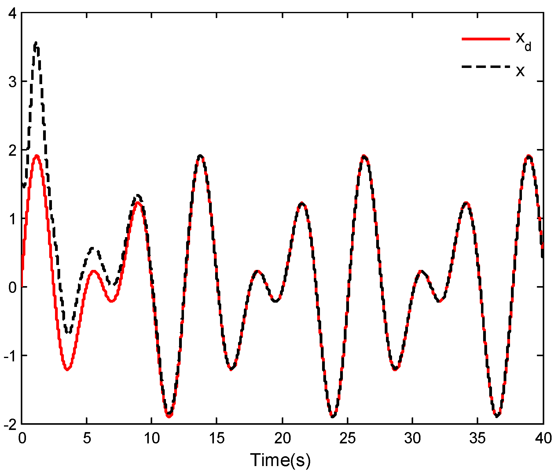
Figure 1. Curve of horizontal position tracking performance.
Mathematics 11 02732 g001
Figure 2. Curve of vertical position tracking performance.
Mathematics 11 02732 g002
Figure 3. Curve of roll angle tracking performance.
Mathematics 11 02732 g003
Figure 4. Tracking error curves of horizontal position and vertical position.
Mathematics 11 02732 g004
Figure 5. Curves of control inputs u1 and u2.
Mathematics 11 02732 g005
Figure 6. Curves of parameter update laws W ^ 1 and W ^ 2 .
Mathematics 11 02732 g006
Figure 7. Curves of parameter update laws Π ^ 1 , Π ^ 2 and Π ^ 3 .
Mathematics 11 02732 g007
Figure 8. Comparison results of horizontal position tracking.
Mathematics 11 02732 g008
Figure 9. Comparison results of vertical position tracking error.
Mathematics 11 02732 g009
Figure 10. Comparison results of roll angle tracking.
Mathematics 11 02732 g010
Figure 11. Comparison results of horizontal position tracking performance.
Mathematics 11 02732 g011
Figure 12. Comparison results of vertical position tracking performance.
Mathematics 11 02732 g012
Figure 13. Comparison results of roll angle tracking performance.
Mathematics 11 02732 g013
Disclaimer/Publisher’s Note: The statements, opinions and data contained in all publications are solely those of the individual author(s) and contributor(s) and not of MDPI and/or the editor(s). MDPI and/or the editor(s) disclaim responsibility for any injury to people or property resulting from any ideas, methods, instructions or products referred to in the content.