Article

Dynamic Output Feedback Quantization Control of a Networked Control System with Dual-Channel Data Packet Loss

College of Internet of Things Engineering, Hohai University, Changzhou 213022, China
*
Author to whom correspondence should be addressed.
Mathematics 2023, 11(11), 2544; https://doi.org/10.3390/math11112544
Submission received: 18 May 2023 / Revised: 29 May 2023 / Accepted: 30 May 2023 / Published: 1 June 2023
(This article belongs to the Special Issue Advanced Stochastic Modelling and Applications)

Abstract

:
In this paper, the design of a dynamic output feedback controller for a networked control system with dual-channel data packet loss and special discrete-time delay is studied, in which the data packet loss is described by the Markov process. In order to effectively alleviate the problem of network congestion, a quantizer was added to the sensor-to-controller channel. The transition probabilities of the Markov process are uncertain, but they exist in the convex sets of known convex polyhedron types. The mode-dependent Lyapunov function was constructed, and a sufficient condition was given to make the closed-loop system stochastically stable and satisfy the performance index. The parameters of the controller were solved by the linear matrix inequality method. Finally, an example of aircraft shows the validity of the proposed approach. A numerical example is compared with other literature, showing the superiority of the proposed approach.

1. Introduction

In 1999, Walsh et al. proposed the concept of network control systems (NCSs) [1]. Since then, NCSs have gained attention from researchers [2]. Due to limited network bandwidths, external interference, and other factors, NCSs usually have uncertain and non-ideal network conditions, such as signal transmission distortion, node communication failure, and data transmission interruption, resulting in network delay, data packet loss, data packet disorder, and so on. These factors may lead to a decline in the performance of NCSs, decreased control quality, and even system instability. Stability is the foundation for the proper functioning of a control system, so research on the stability of NCSs is particularly important. Considering that network delay and packet loss are the main factors affecting the stability of the control system, the research at this stage usually focuses on these two aspects. Moreover, these phenomena are usually random, which can be described by Markov chains.
Markov jump systems (MJSs) serve as stochastic systems with multiple modes, and can describe the transition law for system jumps between different modes using a set of stochastic Markov processes [3,4,5,6,7]. At present, most studies [8,9,10,11,12,13] set the transition probability (TP) matrix as fully known, but in practice, the TP is not fully known, or may not be constant. Thus, the conclusions of the above research may not be applicable. To overcome this difficulty, the TP matrix of the Markov process can be described by a convex polyhedron, which can more accurately represent the uncertain characteristics of the TP of the actual system. The final designed controller can better meet the performance requirements in various random packet loss cases. Hence, research on Markov packet loss based on convex polyhedra holds a certain level of significance.
In addition, dealing with network congestion is another important research direction of NCSs. Because the channel capacity of NCSs is limited, there is always a problem with bandwidth constraints in the process of information transmission. In order to solve this problem, quantization technology emerged. Overall, quantization technology can solve the problem of limited network bandwidth constraints by reducing the amount of information in the communication channel, thereby alleviating network congestion. At present, the method for the support region determination of the quasi-logarithmic quantizer designed for the Laplacian source and an arbitrary variance is proposed in [14]. The encoding scheme proposed in [15] demonstrates the implementation of a simple sub-band encoding and quantization technique in audio signal coding. Moreover, quantization technology has been widely applied in the field of NCSs and has achieved results [16,17,18,19,20,21,22,23]. In fact, as early as the 1950s, Kalman first addressed the problem of quantization feedback control of sampled-data systems and identified the possibility of chaos occurring in closed-loop systems [24]. It is worth noting that introducing quantization into NCSs not only addresses the issue of limited network bandwidth but also introduces certain quantization errors, which will destroy the reliability of the system to a certain extent [25]. Therefore, research on reducing quantization errors is becoming more extensive. In reference [26], the random switching signal of the quantized output feedback controller was designed based on the continuous packet loss times; the researchers also studied the issue of the quantized dynamic output feedback (DOF) control for NCSs with random packet loss. Reference [27] introduced a nonlinear quantizer, established an MJS model describing packet loss, and studied the stability of a typical distributed closed-loop control system connected to the network. Reference [28] used a logarithmic quantizer to quantify the measured output and studied the non-fragile control problem for networked Lipschitz nonlinear systems. In reference [29], the researchers investigated the issue of quantization control in systems with a dynamic quantizer and Markov packet loss, where the dynamic quantizer was composed of a dynamic scaling and a static quantizer. Okano introduced a nonuniform quantizer to minimize the impact of uncertainty on state estimation and reduce the required data rate. Based on this, the stabilization of uncertain systems with limited data rates and damaged communication channels was studied [30].
As there are relatively few papers simultaneously studying packet dropouts in sensor-to-controller (S/C) and controller-to-actuator (C/A) channels, we are interested in dual-channel packet dropouts. Due to limited network bandwidths, a logarithmic quantizer was adopted to quantify the measured output with packet dropouts. Enlightened by the research in [31,32], the Markovian process is used to represent a specific type of delay to describe the packet dropouts. Furthermore, it is assumed that the TP exists in a convex polyhedron, so that the designed DOF controller can apply to multiple TP matrices. Then, when constructing the matrix inequality, the parameters of the convex polyhedron need to be treated. By combining the properties that these parameters accumulate into one, an equivalent matrix inequality is obtained. The parameters of the DOF controller can be solved by the linear matrix inequality (LMI) method to ensure that the system is stochastically stable (SS) and satisfies the specified H performance. Ultimately, an actual instance is given to verify the effectiveness of the proposed approach. The major contributions of this article are as follows:
(1) In this article, an attempt to describe the packet-dropout model with a Markov process of the convex polyhedron type is firstly proposed, so that more general and practical conclusions are obtained.
(2) Although the case involving simultaneous packet dropouts in two channels has been studied [9,32,33], the mutual influence of dual-channel packet dropouts has not been considered. Therefore, this article addresses this issue, providing wider applicability.
Notation: R n represents the n-dimensional Euclidean space. The matrix inequality Ξ < 0 denotes that matrix Ξ is a negative definite matrix. Symbol ∗ represents the corresponding symmetric term in the matrix. E x is the expectation of x.

2. Preliminaries

2.1. System Description

We consider a class of discrete-time systems presented in the following form [31]:
x k + 1 = A x k + B u k + D 1 w k y k = C x k + D 2 w k z k = G x k + G 1 u k + D 3 w k
where x k R n x is the state vector, u k R n u is the control input, w k R n w is the disturbance vector, y k R n y is the measured output, and z k R n z is the output to be controlled.
Remark 1.
We treat the packet dropout as a special case of delay. The number of successive packet dropouts is bounded and the bound is known. We assume r k as the number of packet losses on the C/A channel and set the upper bound as b.Then we consider s k as the number of packet losses on the S/C channel and set the upper bound as d.
It can be seen from Figure 1 that both C/A and S/C channels have packet dropouts. { r k } and { s k } represent the numbers of consecutive packet dropouts in both C/A and S/C channels at time k, respectively. Furthermore, the sequences { r k } and { s k } obey two independent discrete-time homogeneous Markov chains, taking values in the following finite state space:
ϕ 1 = { 0 , , b } , ϕ 2 = { 0 , , d }
To simplify the expression, we denote r k as i and set s k as m. Then we can establish the relationships y ¯ k = y k m , u k = u ¯ k i .
The following formulas define the transition probabilities from the number of packet losses i to the number of packet losses j on the C/A channel side and the number of packet losses m to the number of packet losses n on the S/C channel side.
π i j = P r { u k + 1 = u ¯ k + 1 j | u k = u ¯ k i } λ m n = P r { y ¯ k + 1 = y k + 1 n | y ¯ k = y k m }
Moreover, the system with polytopic uncertainties in the TP matrices Π = [ π i j ] and Λ = [ λ m n ] is considered. Π Φ , Λ . Moreover, Φ , are the polytopes with N 1 and N 2 vertices:
Φ = { Π | Π = s = 1 N 1 ϑ s Π s ; s = 1 N 1 ϑ s = 1 , ϑ s 0 } = { Λ | Λ = t = 1 N 2 σ t Λ t ; t = 1 N 2 σ t = 1 , σ t 0 }
where Π s = [ π i j s ] and Λ t = [ λ m n t ] are the given vertices of the polyhedron.
Remark 2.
The vertices of polytopes have the following special forms:
Π s = π 00 s π 01 s 0 0 π 10 s π 11 s π 12 s 0 π i 0 s π i 1 s π i 2 s 0 π b 0 s π b 1 s π b 2 s π b b s Λ t = λ 00 t λ 01 t 0 0 λ 10 t λ 11 t λ 12 t 0 λ m 0 t λ m 1 t λ m 2 t 0 λ d 0 t λ d 1 t λ d 2 t λ d d t
Some elements in the TP matrices are fixed to 0. Taking π 02 s as an example, π 02 s = P r { u k + 1 = u ¯ k 1 | u k = u ¯ k } it means that the control input at the k + 1 moment is u ¯ k 1 and the control input at the k moment is u ¯ k . Obviously, it is impossible for the data at moment k + 1 to be earlier than the data at the k moment. Moreover, π 02 s represents the element at position (1,3) of the s-th vertex matrix corresponding to this case; thus, π 02 s = 0 .

2.2. Quantization

In this paper, a logarithmic quantizer is used to quantify the measured output, and its quantization set is defined as follows:
Ω = ± ω p h : ω p h = ρ p ω p 0 , h = ± 1 , ± 2 , ω p 0 0
where 0 < ρ p < 1 is the quantization density and ω p 0 > 0 . Thus, a quantizer with the following form is given:
q ( y ¯ p k ) = ω p h , i f 1 1 + δ p ω p h y ¯ p k 1 1 δ p ω p h 0 , i f y ¯ p k = 0 q ( y ¯ p k ) , i f y ¯ p k < 0
where q ( y ¯ p k ) is the quantized output of y ¯ p k and δ p = 1 ρ p 1 + ρ p , p { 1 , 2 , , n y } , in which δ p represents the sector bound.
By the sector-bounded method in [9], we have: | q ( y ¯ p k ) y ¯ p k | δ p y ¯ k . Then we have: q ( y ¯ k ) = ( I + Δ k ) y ¯ k , where Δ k is the quantization error, | Δ k | δ , δ = d i a g δ 1 , δ 2 , , δ p and Δ k = d i a g Δ 1 k , Δ 2 k , , Δ p k . It is obvious that Δ k can be split into I · Δ k δ · δ . Finally, we can obtain the result that Δ k = H F k E , where H = I , E = δ , F k = Δ k δ , and F k T F k I .
Remark 3.
The working principle of the quantizer involves dividing the state space, and each divided region corresponds to a constant. The larger the quantization density, the smaller the quantization error, which can achieve higher control accuracy. The smaller the quantization density, the smaller the required channel capacity; however, at this point, the quantization error becomes larger. Therefore, it is necessary to select an appropriate quantization density to weigh the control effect and channel communication pressure. Thus, the processing of the quantization error and the quantization density selection are the main difficulties. Moreover, different from the literature [14,15,34], this article applies a logarithmic quantizer to the design of the DOF controller for NCSs with dual-channel data packet loss and special discrete-time delay, effectively solving the problem of limited network bandwidth constraints in NCSs.

2.3. Control Strategy and Closed-Loop System

Inspired by reference [32] and considering the quantization problem, the DOF controller with the following form was designed:
x ^ k + 1 = A o x ^ k + B o q ( y ¯ k ) u ¯ k = C o x ^ k
where x ^ k R n x is the state of the controller, y ¯ k R n y is the measurement output after the data packet loss, q ( y ¯ k ) is the quantized output of y ¯ k , and u ¯ k R n u is the output of the controller.
Then, by defining x ¯ k = [ x k T x k d T x ^ k T x ^ k b T ] T and w ¯ k = [ w k T w k d T ] T , we can obtain the following closed-loop system:
x ¯ k + 1 = A ¯ i m x ¯ k + B ¯ m w ¯ k z k = C ¯ i x ¯ k + D ¯ w ¯ k
where
A ¯ i m = A ¯ i m 1 A ¯ i m 2 A ¯ i m 3 A ¯ i m 4 , A ¯ i m 1 = [ A 0 1 × ( d 1 ) ] 0 1 × 1 I d 0 d × 1 A ¯ i m 2 = i ( B C o ) , A ¯ i m 3 = Ξ m [ B o ( I + Δ k ) C ] , B ¯ m 2 = Ξ m [ B o ( I + Δ k ) D 2 ] A ¯ i m 4 = [ A o 0 1 × ( b 1 ) ] 0 1 × 1 I b 0 b × 1 , B ¯ m = B ¯ m 1 B ¯ m 2 , B ¯ m 1 = D 1 0 1 × d 0 d × 1 0 d × d C ¯ i = C ¯ i 1 C ¯ i 2 , C ¯ i 1 = G 0 1 × d , C ¯ i 2 = ¯ i ( G 1 C o ) , D ¯ = D 3 0 1 × d i = δ ( i , 0 ) I δ ( i , 1 ) I δ ( i , b ) I 0 d × 1 0 d × 1 0 d × 1 , ¯ i = δ ( i , 0 ) I δ ( i , 1 ) I δ ( i , b ) I Ξ m = δ ( m , 0 ) I δ ( m , 1 ) I δ ( m , d ) I 0 b × 1 0 b × 1 0 b × 1
Moreover, δ ( a , b ) is the Kronecker delta function and is given as follows:
δ ( a , b ) = 0 , a b 1 , a = b

2.4. Definitions and Lemma

Definition 1
([35]). The system ( 3 ) is said to be SS when w ¯ k = 0 in regard to any initial state, if the following inequality is established:
E k = 0 x ¯ k T x ¯ k | x ¯ 0 , r 0 , s 0 <
Definition 2
([36]). Under the zero initial state and nonzero w ¯ k l 2 [ 0 , ] , the closed-loop system ( 3 ) is said to be SS for given a scalar γ > 0 if the following inequalities are established:
E k = 0 z k T z k < γ 2 k = 0 w ¯ k T w ¯ k
Lemma 1
([37]). For real matrices H, F, E, and F T F I , the matrix inequality Y + H F E + E T F T H T < 0 holds if there exists a scalar ε > 0 such that the following matrix inequality holds:
Y + ε E T E + ε 1 H H T < 0
The main purpose of this article is to design a DOF controller to make the closed-loop system SS and have a given disturbance attenuation level.

3. Main Results

In this part, the sufficient conditions for stochastic stability and H performance are established, and the system (3) with the uncertain TP matrix is taken into consideration.
Theorem 1.
For the given scalar γ > 0 and considering the system ( 3 ) with an uncertain TP matrix, the system ( 3 ) is SS with an H performance index γ if there exists a positive definite matrix P i m s t R ( b + d + 2 ) n x × ( b + d + 2 ) n x , such that the following matrix inequality holds for any i ϕ 1 , m ϕ 2 , s = 1 , , N 1 and t = 1 , , N 2 .
P ¯ i m 0 γ 2 I A ¯ i m B ¯ m P ˜ i m 1 C ¯ i D ¯ 0 I < 0
where
p ¯ i m = s = 1 N 1 t = 1 N 2 ϑ s σ t P i m s t , p ˜ i m = s = 1 N 1 t = 1 N 2 j = 0 b n = 0 d ϑ s σ t π i j s λ m n t P j n s t
Proof of Theorem 1. 
A Lyapunov candidate function is constructed as follows:
V ( x ¯ k , r k , s k | r k = i , s k = m ) = x ¯ k T s = 1 N 1 t = 1 N 2 ϑ s σ t P i m s t x ¯ k
Then we have:
Δ V ( x ¯ k , r k , s k ) = E V ( x ¯ k + 1 , r k + 1 , s k + 1 ) | i , m V ( x ¯ k , i , m ) = n ϕ 2 λ m n t E V ( x ¯ k + 1 , r k + 1 , n ) | i , m V ( x ¯ k , i , m ) = n ϕ 2 λ m n t [ j ϕ 1 π i j s V ( x ¯ k + 1 , j , n ) ] V ( x ¯ k , i , m ) = n ϕ 2 λ m n t ( j ϕ 1 π i j s s = 1 N 1 t = 1 N 2 ϑ s σ t x ¯ k + 1 T P ¯ i m x ¯ k + 1 ) V ( x ¯ k , i , m ) = x ¯ k + 1 T P ˜ i m x ¯ k + 1 x ¯ k T P ¯ i m x ¯ k = x ¯ k T ( P ¯ i m + A ¯ i m T P ˜ i m A ¯ i m ) x ¯ k + w ¯ k T ( B ¯ m T P ˜ i m B ¯ m ) w ¯ k + x ¯ k T ( A ¯ i m T P ˜ i m B ¯ m ) w ¯ k + w ¯ k T ( B ¯ m T P ˜ i m A ¯ i m ) x ¯ k
When w ¯ k = 0 , the following result can be obtained:
Δ V ( x ¯ k , r k , s k ) = x ¯ k + 1 T P ˜ i m x ¯ k + 1 x ¯ k T P ¯ i m x ¯ k = x ¯ k T [ A ¯ i m T P ˜ i m A ¯ i m P ¯ i m ] x ¯ k
Let Θ = A ¯ i m T P ˜ i m A ¯ i m P ¯ i m . In light of the Schur complement [38], (7) indicates the fact that Θ < 0 . Thus, we can obtain
Δ V ( x ¯ k , r k , s k ) κ x ¯ k T x ¯ k κ m x ¯ k T x ¯ k
where κ = m i n λ m i n ( Θ ) , κ m = m i n κ , λ m i n ( Θ ) is the minimal eigenvalue of Θ . As a consequence, the following conclusion holds for any T 1 .
E k = 0 T Δ V ( x ¯ k , r k , s k ) = E V ( x ¯ T + 1 , r T + 1 , s T + 1 ) V ( x ¯ 0 , r 0 , s 0 ) κ m E k = 0 T | | x ¯ k | | 2
Finally, we can obtain the following:
lim T E k = 0 T | | x ¯ k | | 2 V ( x ˜ 0 , r 0 , s 0 ) / κ m E V ( x ˜ T + 1 , r T + 1 , s T + 1 ) / κ m V ( x ˜ 0 , r 0 , s 0 ) / κ m <
On the basis of Definition 1, the closed-loop system (3) is SS with w k = 0 .
Under the situation of the zero initial condition and w ¯ k 0 , we introduce an H index as follows:
J ( T ) = E k = 0 T [ z k T z k γ 2 w ¯ k T w ¯ k ] E k = 0 T [ z k T z k γ 2 w ¯ k T w ¯ k + Δ V ( x ¯ k , r k , s k ) ] = E k = 0 T η k T Υ η k
where
η k = x ¯ k T w ¯ k T T , Υ l p = Υ 11 Υ 21 Υ 22 Υ 11 = P ¯ i m + A ¯ i m T P ˜ i m A ¯ i m + C ¯ i T C ¯ i Υ 21 = B ¯ m T P ˜ i m A ¯ i m + D ¯ T C ¯ i Υ 22 = B ¯ m T P ˜ i m B ¯ m + D ¯ T D ¯ γ 2 I
In light of the Schur complement [38], it can be easy to see that Υ < 0 based on inequality (7); thus, J ( T ) < 0 . When T , it can be seen from Definition 2 that the system ( 3 ) is SS with the H performance index γ . The proof is finished. □
Theorem 2.
For a given scalar γ > 0 , and considering the system ( 3 ) with the uncertain TP matrix, the system ( 3 ) is SS with an H performance index γ if there exists a positive definite matrix P i m s t R ( b + d + 2 ) n x × ( b + d + 2 ) n x , such that the following matrix inequality holds for any i ϕ 1 , m ϕ 2 , s = 1 , , N 1 and t = 1 , , N 2 .
P i m 0 γ ¯ 2 I A ¯ i m B ¯ m P ˜ i m 1 C ¯ i D ¯ 0 I 0 0 C 0 ε I 0 0 D 0 0 ε I < 0
where
P i m = P ¯ i m Λ , Λ = ε δ 2 I d + 1 0 ( d + 1 ) × ( b + 1 ) 0 ( b + 1 ) × ( d + 1 ) 0 ( b + 1 ) × ( b + 1 ) γ ¯ 2 = γ 2 ε δ 2 I , C = I ¯ T Ξ m T ( C T B o T ) D = I ^ T Ξ m T ( D 2 T B o T ) , I ¯ = 0 0 0 I , I ^ = 0 I
Proof of Theorem 2. 
Inequality (7) can be disassembled into the following form:
P ¯ i m 0 γ 2 I A i m B m P ˜ i m 1 C ¯ i D ¯ 0 I + 0 0 0 0 0 C ` 0 0 D 2 ` 0 0 0 0 0 < 0
where
A i m = A ¯ i m 1 A ¯ i m 2 A i m 3 A ¯ i m 4 , A i m 3 = Ξ ( B o C ) B m = B ¯ m 1 B m 2 , B m 2 = Ξ ( B o D 2 ) C ` = Ξ m ( B o F k δ C ) , D 2 ` = Ξ m ( B o F k δ D 2 )
Since F k δ = Δ k is a diagonal matrix, combined with the Kronecker product property, the following equation holds:
0 0 C ` 0 = 0 0 Ξ m ( B o F k δ C ) 0 = 0 0 Ξ m ( B o C ) · F k δ 0 = 0 0 Ξ m ( B o C ) 0 F k δ I d + 1 0 0 0 0 D 2 ` = 0 Ξ m ( B o F k δ D 2 ) = 0 Ξ m ( B o D 2 ) · F k δ = 0 Ξ m ( B o D 2 ) F k δ I d + 1
Therefore, inequality (10) is equivalent to:
P ¯ i m 0 γ 2 I A i m B m P ˜ i m 1 C ¯ i D ¯ 0 I + H ¯ F k E ¯ + E ¯ T F k T H ¯ T < 0
where
H ¯ = 0 0 0 0 0 0 Ξ ( B o C ) 0 0 Ξ ( B o D 2 ) 0 0 E ¯ = δ I d + 1 0 0 0 0 0 0 0 δ I d + 1 0 0
According to Lemma 1, the following inequality can prove that (11) holds:
P ¯ i m 0 γ 2 I A i m B m P ˜ i m 1 C ¯ i D ¯ 0 I + ε E ¯ T E ¯ + ε 1 H ¯ H ¯ T < 0
Moreover, the above formula is equivalent to:
P ¯ i m + Λ 0 γ 2 I + ε δ 2 I A i m B m P ˜ i m 1 C ¯ i D ¯ 0 I 0 0 0 0 C T D T 0 0 ε I 0 0 I 1 0 0 C 0 0 0 D 0 < 0
Based on the Schur complement, the above inequality can certificate that inequality (9) holds. The proof is completed. □
Remark 4.
When the networks are shared by both C/A and S/C channels, there may be interactions between packet losses in the two channels, which can lead to coupling effects, making the controller design more challenging. Taking the situation of b d as an example, we provide the following method to overcome this difficulty. When b < d , the result and the process of proof are similar to the situation where b d .
Theorem 3.
Consider the situation where there exists a mutual effect between the transmissions from the C/A and S/C channels, and we have b d . For the given scalar γ > 0 , the system ( 3 ) is SS with an H performance index γ if there exists a positive definite matrix Q i m s t R ( b + d + 2 ) n x × ( b + d + 2 ) n x , invertible diagonal matrix U R n x × n x , invertible matrix S R n x × n x , and matrices of proper dimensions J R n x × n x , L R n x × n y , M R n u × n x , such that the following matrix inequality holds for any i ϕ 1 , m ϕ 2 , s = 1 , , N 1 and t = 1 , , N 2 .
Q i m 0 γ ¯ 2 I A ˜ i m B ˜ m Q ˜ i m C ˜ i D ˜ 0 I 0 0 C ˘ 0 ε I 0 0 D ˘ 0 0 ε I < 0
where
Q i m = Q ¯ i m Λ , Q ¯ i m = s = 1 N 1 t = 1 N 2 ϑ s σ t Q i m s t , Q ˜ i m = Q ^ i m ξ ξ T Q ^ i m = s = 1 N 1 t = 1 N 2 j = 0 b n = 0 d ϑ s σ t π i j s λ m n t Q j n s t ξ = I d + 1 ( S U + I ) [ I d + 1 ( S U ) 0 ( d + 1 ) × ( b d ) ] I d + 1 ( S U ) 0 ( b d ) × ( d + 1 ) I b + 1 ( S U ) A ˜ i m = A ˜ i m 1 A ˜ i m 2 A ˜ i m 3 A ˜ i m 4 , A ˜ i m 4 = [ J 0 1 × ( b 1 ) ] 0 1 × 1 I b ( S U ) 0 b × 1 A ˜ i m 1 = ˜ i ( B M ) + Ξ ˜ m ( L C ) + A ^ i m 1 + A ^ i m 2 A ^ i m 1 = [ J 0 1 × ( d 1 ) ] 0 1 × 1 I d ( S U ) 0 d × 1 , A ^ i m 2 = [ A 0 1 × ( d 1 ) ] 0 1 × 1 I d 0 d × 1 A ˜ i m 2 = i ( B M ) + [ A ^ i m 1 0 ( d + 1 ) × ( b d ) ] , ^ i = [ δ ( i , 0 ) I δ ( i , d ) I ] A ˜ i m 3 = [ J 0 1 × d ] I d + 1 ( S U ) 0 ( b d 1 ) × ( d + 1 ) + Ξ m ( L C ) , ˜ i = δ ( i , 0 ) I δ ( i , d ) I 0 d × 1 0 d × 1 B ˜ m = B ¯ m 1 Ξ m ( L D 2 ) + Ξ ˜ m ( L D 2 ) 0 ( b + 1 ) × ( d + 1 ) , Ξ ˜ m = δ ( m , 0 ) I δ ( m , d ) I 0 d × 1 0 d × 1 C ˜ i = [ ^ i ( G 1 M ) 0 1 × ( b + 1 ) ] + C ^ i , C ^ i = [ C ¯ i ¯ i ( G 1 M ) ] , D ˜ = D ¯ C ˘ = Ξ ˜ m T ( C T L T ) Ξ m T ( C T L T ) 0 ( b + 1 ) × ( d + 1 ) 0 ( b + 1 ) × ( d + 1 ) , D ˘ = Ξ ˜ m T ( D 2 T L T ) Ξ m T ( D 2 T L T )
Furthermore, if the above matrix inequality is feasible, the parameters of the DOF controller are able to be determined as follows:
A o = S 1 J U 1 B o = S 1 L , C o = M U 1
Proof of Theorem 3. 
The process of the proof involves showing the equivalence between (7) and (17). We just need to prove that the first items of (7) and (17) are equivalent, because the other items can be represented by the linear combination. We define the following matrices:
W = I d + 1 [ I d + 1 U T 0 ( d + 1 ) × ( b d ) ] 0 ( b + 1 ) × ( d + 1 ) I b + 1 U T
ϖ = W 1 0 0 0 0 0 0 I 0 0 0 0 0 0 W 1 0 0 0 0 0 0 I 0 0 0 0 0 0 I 0 0 0 0 0 0 I , ϕ ¯ = I d + 1 0 ( d + 1 ) × ( b + 1 ) 0 ( b + 1 ) × ( d + 1 ) I b + 1 ( U T S )
After performing a congruence transformation to (12) by ϖ , we can obtain the following inequality:
Γ 11 0 γ ¯ 2 I Γ 31 Γ 32 Γ 33 Γ 41 D ˜ 0 I 0 0 Γ 53 0 ε I 0 0 Γ 63 0 0 ε I < 0
where
Γ 11 = W 1 Q ¯ i m W T + W 1 Λ W T , Γ 31 = W 1 A ˜ i m W T , Γ 32 = W 1 B ˜ m Γ 33 = W 1 Q ˜ i m W T , Γ 41 = C ˜ i W T , Γ 53 = C ˘ W T , Γ 63 = D ˘ W T
Let
J = S A o U , L = S B o , M = C o U , P ˜ i m = W 1 Q ^ i m W T , P ¯ i m = W 1 Q ¯ i m W T
Moreover, the calculation shows that the following equations hold:
Λ = W 1 Λ W T , ξ ¯ = W 1 ξ W T , ξ ¯ A ¯ i m = W 1 A ˜ i m W T ξ ¯ B ¯ m = W 1 B ˜ m , C ¯ i = C ˜ i W T , C ξ ¯ T = C ˘ W T , D ξ ¯ T = D ˘ W T
Then we can obtain the following inequality:
P i m 0 γ ¯ 2 I ξ ¯ A ¯ i m ξ ¯ B ¯ m P ˜ i m ξ ¯ ξ ¯ T C ¯ i D ¯ 0 I 0 0 C ξ ¯ 0 ε I 0 0 D ξ ¯ 0 0 ε I < 0
Due to P ˜ i m > 0 , it can be obviously seen that ( P ˜ i m ξ ¯ ) P ˜ i m 1 ( P ˜ i m ξ ¯ ) T 0 . Then ξ ¯ P ˜ i m 1 ξ ¯ T P ˜ i m ξ ¯ ξ ¯ T . Thus, when inequality (16) holds, the following inequality also holds.
P i m 0 γ ¯ 2 I ξ ¯ A ¯ i m ξ ¯ B ¯ m ξ ¯ P ˜ i m ξ ¯ T C ¯ i D ¯ 0 I 0 0 C ξ ¯ 0 ε I 0 0 D ξ ¯ 0 0 ε I < 0
After performing a congruence transformation to (17) by d i a g I , I , ξ ¯ 1 , I , I , I , inequality (9) can be obtained. The proof is finished. □
Theorem 4.
Consider the situation that there exists a mutual effect between the transmissions from the C/A and S/C channels, and b d . For the given scalar γ > 0 , the system ( 3 ) is SS with an H performance index γ if there exists a positive definite matrix Q i m s t R ( b + d + 2 ) n x × ( b + d + 2 ) n x , invertible diagonal matrix U R n x × n x , invertible matrix S R n x × n x , and matrices of proper dimensions J R n x × n x , L R n x × n y , M R n u × n x , such that the following LMI holds for any i ϕ 1 , m ϕ 2 , s = 1 , , N 1 , and t = 1 , , N 2 .
Q ` i m s t 0 γ ¯ 2 I A ˜ i m B ˜ m Q ˘ i m s t C ˜ i D ˜ 0 I 0 0 C ˘ 0 ε I 0 0 D ˘ 0 0 ε I < 0
where
Q ` i m s t = Q i m s t Λ Q ˘ i m s t = j = 0 b n = 0 d π i j s λ m n t Q j n s t ξ ξ T
Furthermore, if the above LMI is feasible, the parameters of the DOF controller can be obtained from (14).
Proof of Theorem 4. 
The process of the proof shows the equivalence between (12) and (18). Let ν = s = 1 N 1 t = 1 N 2 ϑ s σ t . Because ϑ s > 0 , σ t > 0 , we can easily have that the following inequality holds if (18) holds.
ν Q ` i m s t 0 γ ¯ 2 I A ˜ i m B ˜ m Q ˘ i m s t C ˜ i D ˜ 0 I 0 0 C ˘ 0 ε I 0 0 D ˘ 0 0 ε I < 0
Consider the characteristics of convex polyhedron coefficients where s = 1 N 1 ρ s = 1 and t = 1 N 2 σ t = 1 , we can obtain that ν = 1 . Thus, ν ( χ ) = χ , where χ represents the irrelevant items of s and t. Combining the fact that Q ¯ i m = ν ( Q i m s t ) and Q ˜ i m = ν ( Q ˘ i m s t ) , we can finally have
Ψ 11 0 ν γ ¯ 2 I Ψ 31 Ψ 32 Q ˜ i m Ψ 41 Ψ 42 0 ν I 0 0 Ψ 53 0 ν ε I 0 0 Ψ 63 0 0 ν ε I < 0
where
Ψ 11 = Q ¯ i m + ν Λ , Ψ 31 = ν A ˜ i m , Ψ 32 = ν B ˜ m Ψ 41 = ν C ˜ i , Ψ 42 = ν D ˜ , Ψ 53 = ν C ˘ , Ψ 63 = ν D ˘
According to the property that ν ( χ ) = χ , (12) is equivalent to (19). Thus, when (18) holds, (12) also holds, and the system ( 3 ) is SS with an H performance index γ . As a consequence, the proof is finished. □

4. Examples

4.1. A Practical Example

This section presents an aircraft system model [39] to demonstrate the effectiveness of the designed DOF controller. We consider a longitudinal dynamic model of an aircraft with a speed of Mach 0.3 and a flight altitude of 5000 m above sea level. If the sampling time is set to 0.025 s, the parameters of the discrete system can be expressed as follows:
A = 0.9862 0.0243 0 0.0264 0.9894 0 0.0003 0.0249 1 , B = 0.0038 0.0810 0.0010 , D 1 = 0.1 0.1 0.2 C = 1 0 1 , D 2 = 0.35 , G = 1 0.5 1 , G 1 = 0.25 , D 3 = 0.09 .
The initial conditions of the system and DOF controller are selected as x 0 = x ^ 0 = [ 0 0 0 ] T . Moreover, the initial modes r 0 and s 0 are assumed to be 0, and δ 1 is set at 0.05. Suppose that the upper limit of the packet loss of the C / A channel is b = 2 and that of the S / C channel is d = 1 . The TP matrices of the Markov process are unknown; however, they reside in the polytopes with the following two vertices:
Π 1 = 0.3 0.7 0 0.2 0.5 0.3 0.4 0.1 0.5 , Π 2 = 0.6 0.4 0 0.2 0.2 0.6 0.5 0.2 0.3 , Λ 1 = 0.4 0.6 0.1 0.9 , Λ 2 = 0.3 0.7 0.9 0.1 .
The simulation time is in the range of k = 0 , 1 , , 500 . The disturbance noise w k is set at w k = 0.2 e 0.1 k × s i n ( 0.1 k ) . Based on the MATLAB LMI toolbox, the minimum disturbance attenuation level can be obtained as γ m i n = 0.2001 , and the parameters of the DOF controller can be designed as follows, according to (14). For the ease of implementation, we set U = 10 I :
A o = 0.0040 0.0002 0.0006 0.0011 0.0039 0.0011 0.0019 0.0008 0.0054 , B o = 0.0117 0.0117 0.0234 C o = 0.0730 0.0363 0.0731
The actual TP matrices are taken into consideration as follows:
Λ = 0.51 0.49 0 0.20 0.29 0.51 0.47 0.17 0.36 , Π = 0.36 0.64 0.42 0.58 .
which means that ϑ 1 = 0.3 , ϑ 2 = 0.7 , σ 1 = 0.6 , σ 2 = 0.4 . Using the resulting DOF controller, we provide the time-domain simulation results.
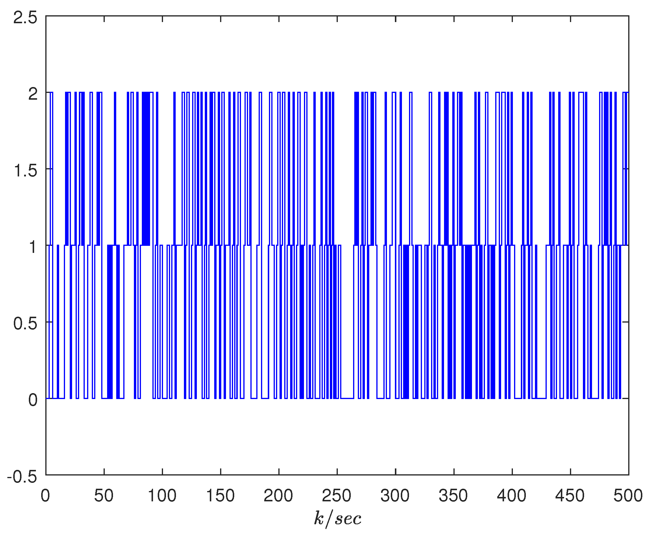
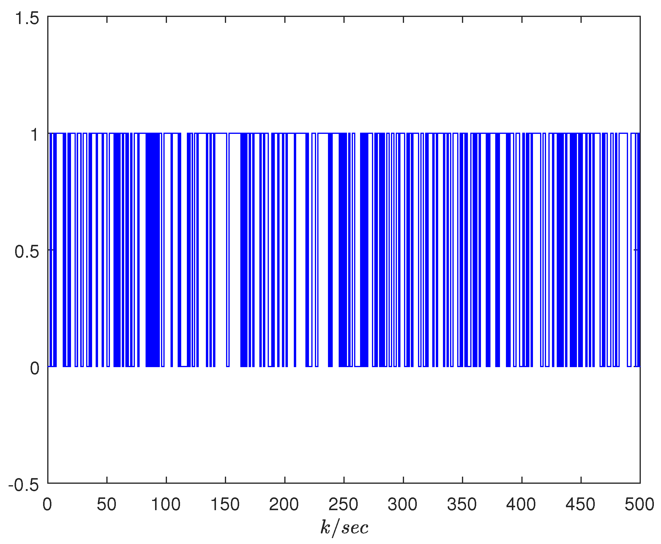
Figure 2 and Figure 3 display the evolution of modes r k and s k , respectively, which represent the number of consecutive packet losses in C/A and S/C channels. From Figure 2, it can be seen that r k has three modes: no packet loss ( r k = 0 ), one packet loss ( r k = 1 ), and two consecutive packet losses ( r k = 2 ). From Figure 3, it can be seen that s k has two modes: no packet loss ( s k = 0 ) and one packet loss ( s k = 1 ).
Figure 4 and Figure 5 exhibit the trajectories of state x k and the output to be controlled z k , respectively, which both have a stable tendency with added disturbances. This indicates that the system is SS and has anti-interference abilities. The measured output y k , the measured output with packet loss y ¯ k , and the quantized measured output with packet loss q ( y ¯ k ) are plotted in Figure 6. Due to the long simulation time, the three curves in Figure 6 almost coincide, so a small local time diagram with a time length of 10 is given. The inconsistency between the solid blue line and the dashed black line indicates packet loss. Moreover, it can be further seen from Figure 6 that q ( y ¯ k ) and y ¯ k are close. Hence, the quantization error caused by quantifying y ¯ k is relatively small. In general, Figure 4, Figure 5 and Figure 6 indicate that the designed DOF controller is feasible and effective.

4.2. A Numerical Example and Comparison

Since the quantization control of data loss in dual channels is also considered in reference [26], the method proposed in this paper is compared with the method in reference [26] to demonstrate its superiority. The numerical example in reference [26] is adopted and the other parameters are the same. The system parameters are given as follows:
A = 0.5 0.1 0.1 0.6 , B = 0.5 0.3 , D 1 = 0.2 0.1 , D 2 = 0 D 3 = 0.1 , C = 0.2 0.1 , G = 0.1 0.1 , G 1 = 0.2 .
The initial conditions of the system and DOF controller are selected as x 0 = [ 1 1 ] T and x ^ 0 = [ 0 0 ] T , respectively. Moreover, the initial modes r 0 and s 0 are assumed to be 0, and δ 1 is set to be 0.05. To obtain the same TP matrices as reference [26], the vertices of the convex polyhedron are selected as follows:
Π 1 = 0.95 0.05 0 0.7 0.12 0.18 1 0 0 , Π 2 = 0.85 0.15 0 0.9 0.08 0.02 1 0 0 Λ 1 = 0.92 0.08 1 0 , Λ 2 = 0.88 0.12 1 0 .
After letting ϑ 1 = ϑ 2 = σ 1 = σ 2 = 0.5 , we can obtain the following TP matrices:
Λ = 0.9 0.1 0 0.8 0.1 0.1 1 0 0 , Π = 0.9 0.1 1 0 .
By using the MATLAB LMI toolbox, the minimum disturbance attenuation level can be obtained, as given in Table 1. From Table 1, it can be seen that the disturbance attenuation level γ m i n is 0.0901 by solving Theorem 4, which is smaller than 0.11 in reference [26]. It means that the controller designed in this paper enhances the closed-loop system’s anti-interference ability. To facilitate the comparison, we set U = 10 I and select the disturbance attenuation level γ = 0.95 . At this point, the parameters of the DOF controller can be obtained as follows, in light of ( 14 ) .
A o = 0.0535 0.0023 0.0258 0.0826 , B o = 1.0186 0.3727 , C o = 0.0125 0.0076
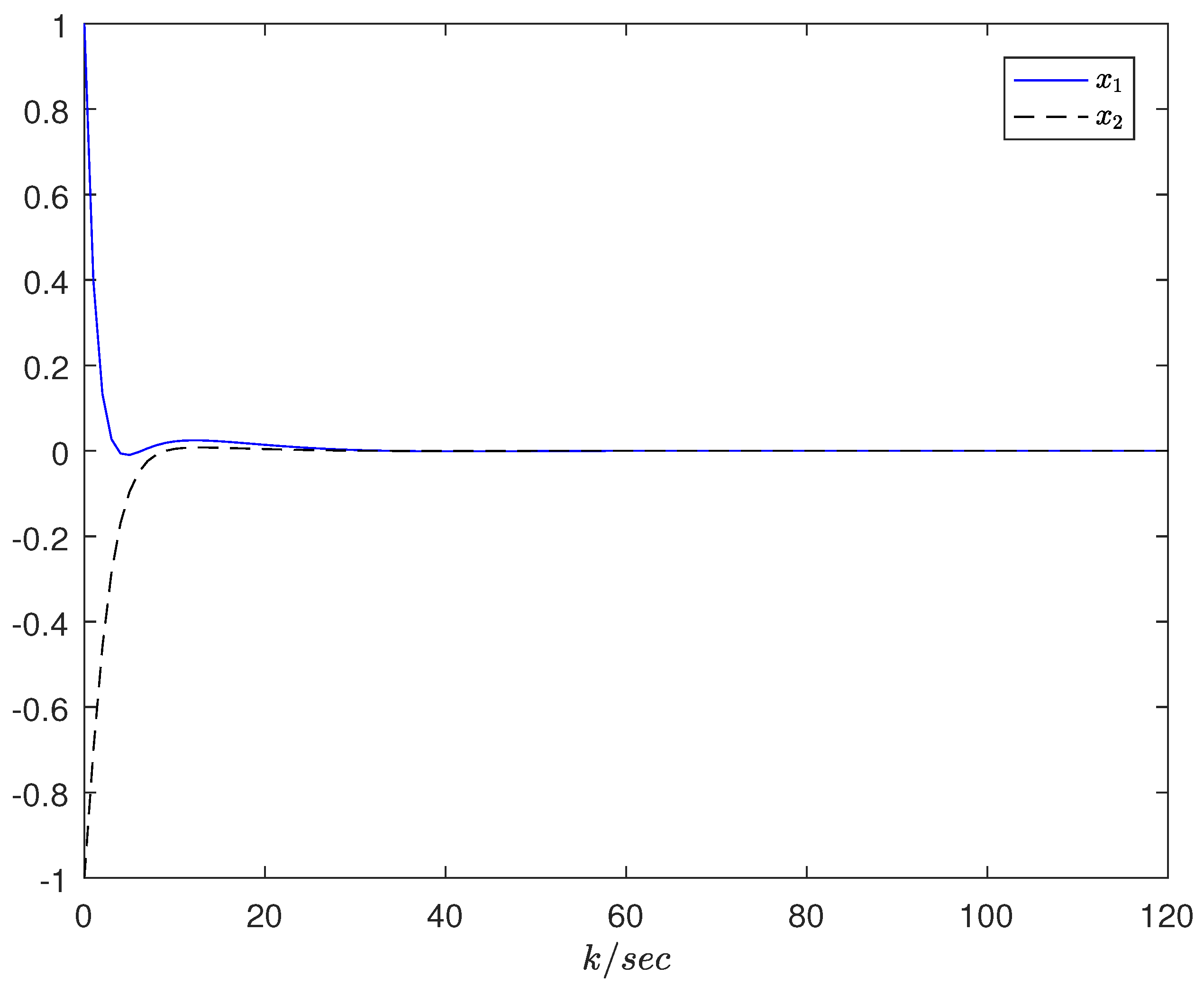
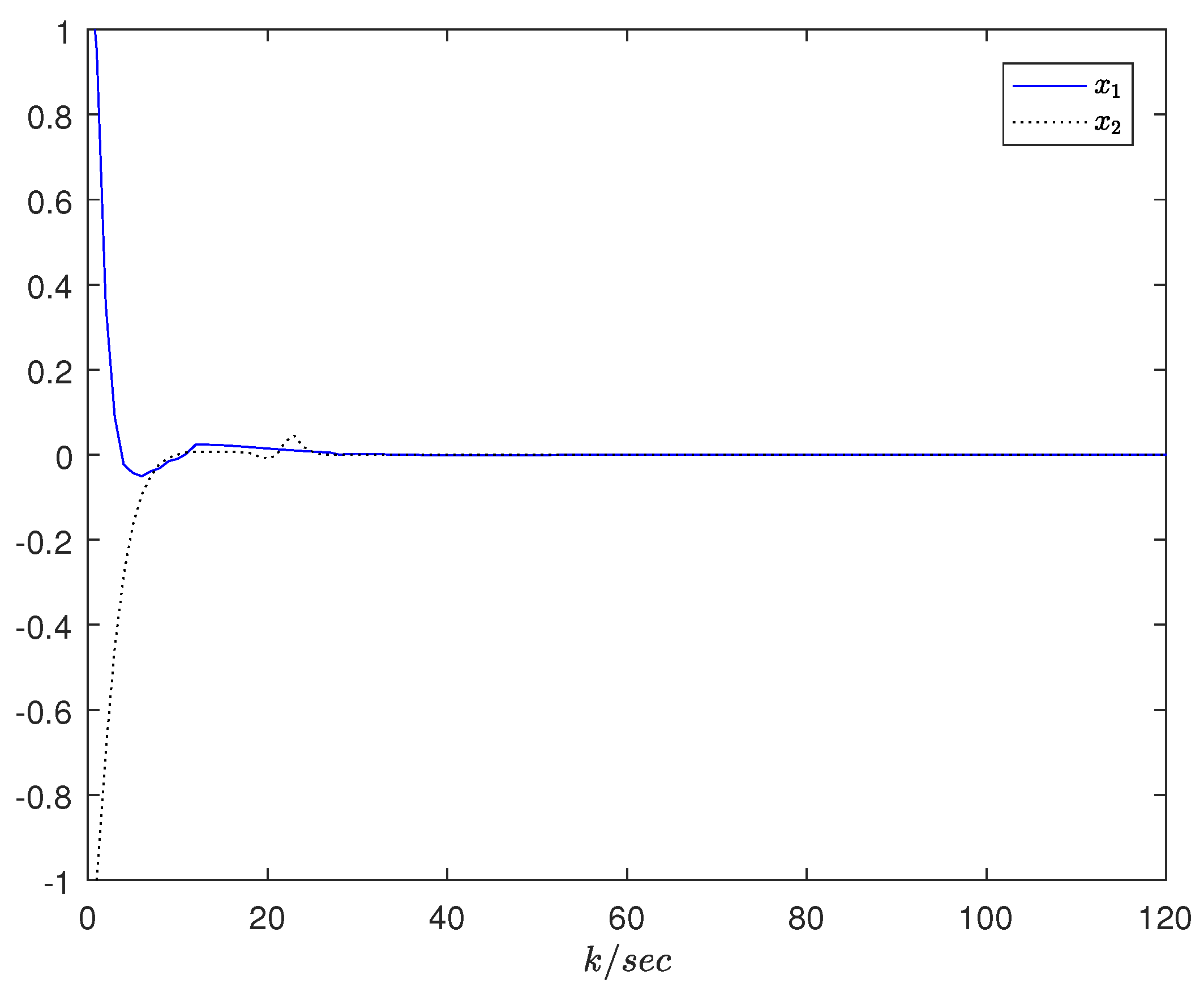
After using the controller parameters obtained by the method in this paper, we can obtain the state trajectory diagram, as shown in Figure 7. By comparing Figure 7 and Figure 8, it can be seen that, on the premise of ensuring that the response speed is basically the same as that in the literature [26], the method proposed in this paper has a smaller H performance index (see Table 1) and better anti-interference abilities. Moreover, when the transition probabilities are not fully known, the conclusion in reference [26] is no longer applicable. Since the TP matrix in this paper is described by convex polyhedron, it can deal with the situation where the transition probabilities are uncertain or unavailable. Hence, compared with reference [26], the method proposed in this paper has more extensive applicability.

5. Conclusions

In this article, we studied the DOF control problem for NCSs with quantization effects and random data loss. The Markov process was used to describe the data loss. Sufficient conditions were presented by adopting the Lyapunov function approach and LMI approach to make the system SS. The designed controller enables the NCSs to meet the H performance index under certain bandwidth constraints and considering quantization errors. The quantitative DOF controller is designed using the LMI method, and the controller parameters are determined to ensure that the closed-loop system is randomly stable and achieves the desired disturbance attenuation level. Finally, a practical example of an aircraft model shows the validity of the proposed approach. Furthermore, a numerical example was chosen and compared with other literature, demonstrating the superiority of the proposed approach. It is worth noting that the research results of this article can be further extended to MJSs with repeated scalar nonlinearities.

Author Contributions

Ideas, writing—review, editing, F.Z. and M.H.; derivation and simulation experiments, writing—original draft, F.Z. and M.G. All authors have read and agreed to the published version of the manuscript.

Funding

This work was supported by the Natural Science Foundation of Jiangsu Province under grant BK20221232 and the National Natural Science Foundation of China under grant 62073119.

Data Availability Statement

Not applicable.

Conflicts of Interest

The authors declare no conflict of interest. The funders had no role in the design of the study; in the collection, analyses, or interpretation of data; in the writing of the manuscript; or in the decision to publish the results.

Abbreviations

The following abbreviations are used in this manuscript:
NCSsnetwork control systems
MJSMarkov jump system
S/Csensor-to-controller
C/Acontroller-to-actuator
DOFdynamic output feedback
TPtransition probability
SSstochastically stable
LMIlinear matrix inequality

References

  1. Walsh, G.; Ye, H.; Bushnell, L. Stability analysis of networked control systems. In Proceedings of the American Control Conference, San Diego, CA, USA, 2–4 June 1999; pp. 2876–2880. [Google Scholar]
  2. Mishra, S.; Pat, A.; Appasani, B.; Jha, A.; Kumar, M.; Pal, V.; Gautam, M. Event-triggered fractional-order PID control of fractional-order networked control system. Electr. Eng. 2021, 690, 205–216. [Google Scholar]
  3. Tian, Y.; Yan, H.; Zhang, H.; Cheng, J.; Shen, H. Asynchronous output feedback control of hidden semi-markov jump systems with random mode-dependent delays. IEEE Trans. Autom. Control 2022, 67, 4107–4114. [Google Scholar] [CrossRef]
  4. Hua, M.; Zheng, D.; Deng, F. Partially mode-dependent l2-l filtering for discrete-time nonhomogeneous Markov jump systems with repeated scalar nonlinearities. Inf. Sci. 2018, 451–452, 223–239. [Google Scholar] [CrossRef]
  5. Boukas, E.K. H control of discrete-time Markov jump systems with bounded transition probabilities. Optim. Control Appl. Meth. 2009, 30, 477–494. [Google Scholar] [CrossRef]
  6. Ma, H.; Jia, Y. H2 control of discrete-time periodic systems with Markovian jumps and multiplicative noise. Int. J. Control 2013, 86, 1837–1849. [Google Scholar] [CrossRef]
  7. Cheng, J.; Xie, L.; Park, J.H.; Yan, H. Protocol-based output-feedback control for semi-Markov jump systems. IEEE Trans. Autom. Control 2022, 67, 4346–4353. [Google Scholar] [CrossRef]
  8. Smith, S.; Seiler, P. Estimation with lossy measurements: Jump estimators for jump systems. IEEE Trans. Autom. Control 2015, 48, 2163–2171. [Google Scholar] [CrossRef]
  9. Zhang, W.; Yu, L. Output feedback stabilization of networked control systems with packet dropouts. IEEE Trans. Autom. Control 2007, 52, 1705–1710. [Google Scholar] [CrossRef]
  10. Wu, J.; Chen, T. Design of networked control systems with packet dropouts. IEEE Trans. Autom. Control 2007, 52, 1314–1319. [Google Scholar] [CrossRef]
  11. Shi, Y.; Yu, B. Output feedback stabilization of networked control systems with random delays modeled by Markov chains. IEEE Trans. Autom. Control 2009, 54, 1668–1674. [Google Scholar]
  12. Shi, Y.; Yu, B. Robust mixed H2/H control of networked control systems with random time delays in both forward and backward communication links. Automatica 2011, 47, 754–760. [Google Scholar] [CrossRef]
  13. Wu, D.; Wu, J.; Chen, S. Separation principle for a networked control systems with multiple-packet transmission. IET Control Theory Appl. 2011, 5, 507–513. [Google Scholar] [CrossRef]
  14. Aleksić, D.; Perić, Z.; Nikolić, J. Support region determination of the quasilogarithmic quantizer for Laplacian Source. Prz. Elektrotech. 2012, 88, 130–132. [Google Scholar]
  15. Tomić, S.; Perić, Z.; Tančić, M.; Nikolić, J. Backward adaptive and quasi-logarithmic quantizer for sub-band coding of audio. Inf. Technol. Control 2018, 47, 131–139. [Google Scholar]
  16. Kavikumar, R.; Kwon, O.-M.; Kaviarasan, B.; Sakthivel, R. Anti-disturbance control design for interval type-2 fuzzy stochastic systems with input quantization. IEEE Trans. Fuzzy Syst. 2022. [Google Scholar] [CrossRef]
  17. Wu, C.; Zhao, X. Quantized dynamic output feedback control and L2-gain analysis for a networked control systems: A hybrid approach. IEEE Trans. Netw. Sci. Eng. 2021, 8, 575–587. [Google Scholar] [CrossRef]
  18. Zhao, L.; Ma, X.; Wang, J. Networked predictive control for linear systems with quantizers by an event-driven strategy. J. Frankl. Inst. 2019, 356, 3245–3269. [Google Scholar] [CrossRef]
  19. Hua, M.; Qian, Y.; Deng, F.; Fei, J.; Cheng, P.; Chen, H. Filtering for discrete-time Takagi-Sugeno fuzzy nonhomogeneous Markov jump systems with quantization effects. IEEE Trans. Cybern. 2022, 52, 982–995. [Google Scholar] [CrossRef]
  20. Han, Q.; Liu, Y.; Yang, F. Optimal communication network-based H quantized control with packet dropouts for a class of discrete-time neural networks with distributed time delay. IEEE Trans. Neural Netw. Learn. Syst. 2016, 27, 426–434. [Google Scholar] [CrossRef]
  21. Zhang, M.; Shi, P.; Ma, L.; Cai, J.; Su, H. Network-based fuzzy control for nonlinear markov jump systems subject to quantization and dropout compensation. Fuzzy Sets Syst. 2019, 371, 96–109. [Google Scholar] [CrossRef]
  22. Yang, R.; Shi, P.; Liu, G.; Gao, H. Network-based feedback control for systems with mixed delays based on quantization and dropout compensation. Automatica 2011, 47, 2805–2809. [Google Scholar] [CrossRef]
  23. Sakthivel, R.; Kavikumar, R.; Mohammadzadeh, A.; Kwon, O.-M.; Kaviarasan, B. Fault estimation for mode-dependent IT2 fuzzy systems with quantized output signals. IEEE Trans. Fuzzy Syst. 2021, 29, 298–309. [Google Scholar] [CrossRef]
  24. Kalman, R. Nonlinear aspects of sampled-data control systems. Proc. Symp. Nonlinear Circuits Anal. 1956, 6, 273–313. [Google Scholar]
  25. Wu, B.; Liang, H.; Chang, X.; Zhao, X. Fuzzy H output feedback control for nonlinear NCSs with quantization and stochastic communication protocol. IEEE Trans. Fuzzy Syst. 2021, 29, 2623–2634. [Google Scholar] [CrossRef]
  26. Yu, M.; Bai, S.; Yang, T.; Zhang, J. Quantized output feedback control of networked control systems with packet dropout. Int. J. Control Autom. Syst. 2018, 16, 2559–2568. [Google Scholar] [CrossRef]
  27. Wang, H.; Ga, R.; Zhang, Q.; Wen, S. Robust controller design for a networked control system with packet dropout and quantization error. In Proceedings of the 2015 International Conference on Advanced Mechatronic Systems (ICAMechS), Beijing, China, 22–24 August 2015; pp. 552–556. [Google Scholar]
  28. Ma, W.; Yang, Z. Non-fragile H control for networked lipschitz nonlinear system subject to quantization and packet dropout. WIT Trans. Inf. Commun. Technol. 2014, 55, 629–638. [Google Scholar]
  29. Che, W.; Jin, X.; Ye, D. Quantized state-feedback H control of networked control systems with Markov dropouts. In Proceedings of the 2012 24th Chinese Control and Decision Conference (CCDC), Taiyuan, China, 23–25 May 2012; pp. 406–411. [Google Scholar]
  30. Okano, K.; Ishii, H. Stabilization of uncertain systems with finite data rates and markovian packet losses. IEEE Trans. Control Netw. Syst. 2014, 1, 298–307. [Google Scholar] [CrossRef]
  31. Wang, D.; Wang, J.; Wang, W. Output feedback control of networked control systems with packet dropouts in both channels. Inf. Sci. 2013, 221, 544–554. [Google Scholar] [CrossRef]
  32. Chen, H.; Gao, J.; Shi, T.; Lu, R. H control for a networked control systems with time delay, data packet dropout and disorder. Neurocomputing 2016, 179, 211–218. [Google Scholar] [CrossRef]
  33. Mahmoud, M.S. Dynamic output feedback of networked control systems with partially known Markov chain packet dropouts. Optim. Control Appl. Methods 2015, 36, 29–44. [Google Scholar] [CrossRef]
  34. Perić, Z.; Nikolic, J. High-quality laplacian source quantisation using a combination of restricted and unrestricted logarithmic quantisers. IET Signal Process. 2012, 6, 633–640. [Google Scholar] [CrossRef]
  35. Kao, Y.; Xie, J.; Wang, C. Stabilization of singular Markovian jump systems with generally uncertain transition rates. IEEE Trans. Autom. Control 2014, 59, 2604–2610. [Google Scholar] [CrossRef]
  36. Dong, S.; Su, H.; Shi, P.; Lu, R.; Wu, Z. Filtering for discrete-time switched fuzzy systems with quantization. IEEE Trans. Fuzzy Syst. 2017, 25, 1616–1628. [Google Scholar] [CrossRef]
  37. Hua, M.; Bian, C.; Chen, J.; Fei, J. Quantized H filtering for continuous-time nonhomogeneous Markov jump systems. Circ. Syst. Signal Process. 2020, 39, 3833–3857. [Google Scholar] [CrossRef]
  38. Boyd, S.; Ghaoui, L.E.; Feron, E.; Balakrishnan, V. Linear matrix inequalities in system and control theory. In SIAM Studies in Applied Mathematics; SIAM: Philadelphia, PA, USA, 1994. [Google Scholar]
  39. Li, X.; Sun, S. H control for networked stochastic non-linear systems with randomly occurring sensor saturations, multiple delays and packet dropouts. IET Control Theory Appl. 2017, 11, 2954–2963. [Google Scholar] [CrossRef]
Figure 1. The framework of NCSs.
Mathematics 11 02544 g001
Figure 2. Mode r k in the C/A channel.
Mathematics 11 02544 g002
Figure 3. Mode s k in the S/C channel.
Mathematics 11 02544 g003
Figure 4. State trajectories of system x k .
Mathematics 11 02544 g004
Figure 5. The output to be controlled, z k .
Mathematics 11 02544 g005
Figure 6. The measured output, y k , the measured output with packet loss, y ¯ k , and the quantized measured output with packet loss, q ( y ¯ k ) .
Mathematics 11 02544 g006
Figure 7. State x k by using the methods in this paper.
Mathematics 11 02544 g007
Figure 8. State x k by using the methods in reference [26].
Mathematics 11 02544 g008
Table 1. Optimal H performance index γ m i n .
Theorem 4Literature [26]
Performance index γ m i n 0.09010.11
Disclaimer/Publisher’s Note: The statements, opinions and data contained in all publications are solely those of the individual author(s) and contributor(s) and not of MDPI and/or the editor(s). MDPI and/or the editor(s) disclaim responsibility for any injury to people or property resulting from any ideas, methods, instructions or products referred to in the content.