Abstract
Cranial implants, especially custom made implants, are complex, important and necessary in craniofacial fracture restoration surgery. However, the classical procedure of the manual design of the implant is time consuming and complicated. Different computer-based techniques proposed by different researchers, including CAD/CAM, mirroring, reference skull, thin plate spline and radial basis functions have been used for cranial implant restoration. Computer Aided Geometric Design (CAGD) has also been used in bio-modeling and specifically for the restoration of cranial defects in form of different spline curves, namely rational curves, B-spline and Non-Uniform Rational B-Spline (NURBS) curves. This paper gives an in-depth comparison of existing techniques by highlighting the limitations and advantage in different contexts. The construction of craniofacial fractures is made using different Bézier-like functions (Ball, Bernstein and Timmer basis functions) and is analyzed in detail. The and cubic Ball curves are performed well for construction of the small fractured part. Any form of fracture is constructed using this approach and it has been effectively applied to frontal and parietal bone fractures. However, B-spline and NURBS curves can be used for any type of fractured parts and are more friendly user.
Keywords:
Ball curves; parametric continuity; geometric continuity; B-spline curves; NURBS curves; craniofacial fracture reconstruction MSC:
65D17; 68U07; 93B51; 41A15; 94C30
1. Introduction
The most complex part of the human body is the craniofacial region because it consists of different bones integrated together in a very complex way. The bones that make up this region are shown in Figure 1, taken from [1]. There can be several reasons for cranial fractures such as sports injury, falls, trauma and home violence. Different tools, including X-rays, Magnetic Resonance Imaging (MRI) and Computed tomography (CT) scan are used to diagnose the craniofacial fractures. The main goal of craniofacial fracture reconstruction is to get and restore both normal physiological function and esthetics. As discussed earlier, the cranial part is a complicated anatomical region of the body. Therefore, to diagnose the craniofacial region is always a challenging task both for the surgeon and the radiologist. Most of the time, only radiologists can detect the fractures using radiological imaging tools.
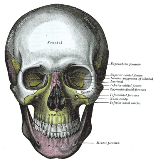
Figure 1.
Craniofacial bones [1].
To overcome this problem, the latest computer technology has opened new doors for engineers, doctors and mathematicians to guide in construction and diagnosis of fractures caused by trauma and tumors. The CAD/CAM process has been used by [2,3] for the construction of the cranial area. This CAD/CAM process is time consuming and requires technical staff help, which causes high costs and low efficiency. One more down side of this process is that this method is not good for the construction of large format fractures. Cubic trigonometric B-spline basis functions have been used by [4] for geometric modeling. Craniofacial fractures in 3D form have been constructed by [1] using Bézier-like functions. The mirroring method for craniofacial fractures was proposed by [5]. This method is applicable for the fracture on the single side of the skull and will not work for multiple bone fractures. The surface interpolation or deformation method is proposed by [6]. Using this method, the fractured part is constructed using the non-fractured part. Wu et al. [7] and Shui et al. [8] introduced the adaptive deformation method for the restoration of a cranial implant. This method is based on a reference skull by first constructing the reference skull then constructing the patients fracture. The authors in [9] suggested a computer imaging system to generate manual construction; to maintain the accuracy, they construct 20 different parts involving nose, contours, hairstyle and eyes. Meanwhile, a technique based on soft tissue thickness was proposed by [10].
Rational cubic Ball curves with continuity and two shape parameters have been used by [11] for frontal bone fracture reconstruction. Occipital bone fracture has been constructed by [12] using cubic B-spline curves. The parietal bone has been reconstructed using rational Ball curves by [13]. NURBS curves with degree three have been used for the construction of multiple bone fractures by [14]. Hierarchical B-spline curve was used by [15,16] for cranial implants. They developed markers to use computer technology to recreate the face area. Kang [17] and Shui et al. [18] utilized thirty seven landmarks to construct craniofacial fractures. Facial reconstruction is dependent on the registration of dense points. Suetens et al. [19] used Thin Plate Spline (TPS) to reconstruct the craniofacial fracture taking 52 landmarks. Turner et al. [20] adopted Iterative Closest Point (ICP), taking into account a 30-skull model database. Claes et al. [21] presented Principal Component Analysis (PCA). Carr et al. [22] used radial basis function. Parietal bone fracture has been constructed by [23] using a parallel curve algorithm.
The scheme based on 37 land marks was used by [17,18] for the restoration of the fractured part. Radial bases functions and thin plate spline were used by [19,22] for facial reconstruction. In thin plate spline, authors used 52 landmarks. Thirty skull model databases were used in adopted iteration closest point for facial fracture reconstruction by [20]. Principal component analysis was used by [21] for fracture reconstruction.
This paper carries out the following two comparisons:
- A comparison between the existing scheme-like techniques (mirroring, reference skull, thin plate spline, iterative closest point, radial basis functions, the technique using CAD/CAM) and the techniques using spline curves.
- A comparative analysis of techniques based on spline curves.
The rest of the paper is organized in four sections. In Section 2, different Bézier-like functions and curves with their applications are discussed. Different continuity conditions between two curve segments are also a part of this section. Section 3 deals the two types of comparison analyses. First, the comparison between exiting techniques and the techniques based on Bézier-like functions. Second, the comparison between the different techniques based on Bézier-like functions. The last section is for conclusions.
2. Theoretical Foundation
This section explains different techniques based on spline curves, which have been used for the construction of craniofacial fractures.
2.1. Bézier-like Functions
Different cubic basis functions are defined in [24] as:
Here, m is a positive integer. When the functions become a Ball basis defined by [25], and for equation one represents the Bézier and Timmer basis functions defined in [26,27]. The graphical behavior of the basis functions for different values of m is represented in Figure 2; has been used in this work.
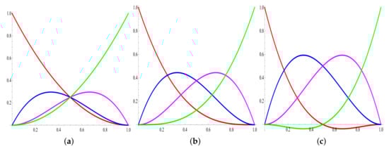
Figure 2.
Graphical behavior of basis functions with different values of m. (a) Ball basis functions ; (b) Bézier basis functions ; (c) Timmer basis functions .
The Bézier-like functions defined in Equation (1) satisfy the basic properties such as non-negativity, symmetricity, monotonicity and partition of unity.
2.2. Curve Segment and Continuity
The cubic Ball curve is defined as . Here, are control points and are Ball basis functions defined in Equation (1). The cubic Ball curve obeys all basic properties, including convex hull, coordinate system independence and the variation diminishing property.
In order to construct the craniofacial fractures, two or more curve segments are required. The smoothness and continuity between two curve segments (at knot points) is an important issue. Parametric and geometric continuities are commonly used to get the smoothness at the knots. Another use of the parametric and geometric condition is that it provides the relation to evaluate the intermediate control points.
2.3. Parametric and Geometric Continuity
Let and be two curve segments. The parametric continuity between two segments is defined as:
continuity: where m is the number of derivatives at the adjacent end points, which are the same:
, and are the continuity between two segments, as shown in Figure 3. The geometric continuity between segments can be defined as:
where is an arbitrary value.

Figure 3.
Parametric continuity. (a) continuity ; (b) continuity , ; (c) continuity .
For , continuity reduces to continuity. The graphical representation of geometric continuity between two segments is given in Figure 4.
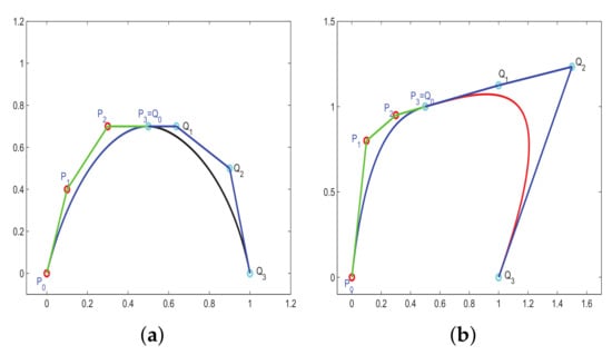
Figure 4.
Geometric continuity. (a) continuity ; (b) continuity .
In the literature, different rational Ball curves with , and continuity have been used for fracture reconstruction. rational cubic Ball curve has been used in [11], which is defined as:
where:
satisfies the following conditions:
where , are positive shape parameters, the endpoints of each segment is represented by , and tangent vectors at and , are , , respectively.
The above scheme with continuity has been used for the construction of frontal bone fracture, as shown in Figure 5.
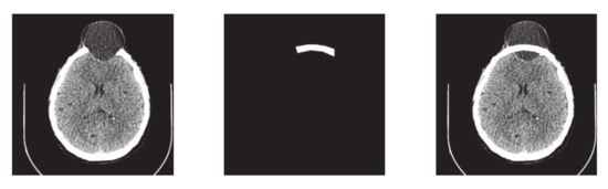
Figure 5.
Fracture reconstruction using rational cubic Ball curves.
In [28], the authors have constructed the fractured part using rational Ball curves, which is defined as:
where:
and , , and represents the control points and , are shape parameters. and continuity between two adjacent segments can be defined as:
where:
Using the geometric continuity condition definition, the continuity condition has been derived as follows:
where are control points and are shape controls to be calculated. Figure 6 shows the parietal bone fracture using the rational Ball curve.
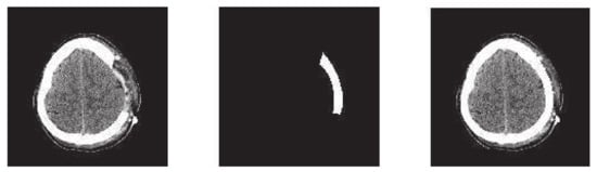
Figure 6.
Construction of fractured part using rational Ball curves.
In [13], the authors used rational Ball curves for fracture reconstruction with four shape parameters. The continuity conditions are:
where represents the control points on the curve and and represents the shape control to be calculated. The rational Ball curve has been used for the construction of parietal bone fracture, which is shown in Figure 7.
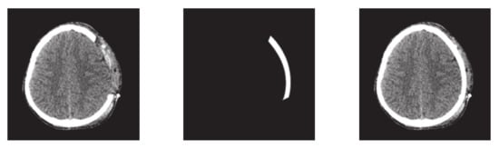
Figure 7.
Construction of fractured part using rational Ball curves.
To define the cubic B-spline basis, consider the set of the knot vector with non-decreasing elements (knots), i.e., ; say . The cubic B-spline of the jth order with degree n is defined as:
for and These bases have been used for the construction of the occipital bone fracture by [12]. The reconstructed occipital fracture is shown in Figure 8.
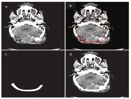
Figure 8.
Construction of fractured part using B-spline. (a) Original CT scan image; (b) Construction of fractured part boundary curves; (c) Fractured part in DICOM format; (d) Implanted fractured part.
In [14], the authors used NURBS curves. The dth-degree NURBS curve is defined by:
where are the weights, are the control points and represents the dth-degree B-spline functions on non-uniform knots.
as:
for and
For simplicity, assume that and for all Setting:
Equation (15) can be written as:
The are the rational basis functions.
These bases are piecewise rational functions on The authors used the NURBS curve for the construction of the parietal bone fracture on the left hand side, as shown in Figure 9.
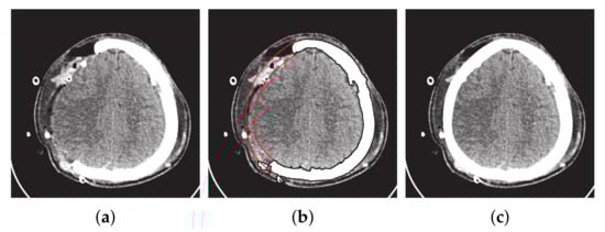
Figure 9.
Construction of fractured part using NURBS curves. (a) Original image. (b) Fractured part boundary curves reconstruction (red curves show the inner and outer boundary curves). (c) Reconstruction of fracture part into DICOM format.
3. Comparative Analysis
3.1. Existing vs. Bézier-like Function Techniques
This subsection addresses the comparison between the existing techniques and the techniques based on spline curves. Table 1 gives a detailed comparison of the different techniques.

Table 1.
Comparison of existing techniques and techniques based on spline curves.
3.2. Comparison of Techniques Using Spline Curves
This subsection addresses the critical analysis of different schemes based on Bézier-like functions such as , , rational cubic Ball curves, NURBS curves and B-spline curve of degree three. Different types of fractures have been constructed using CT scan, such as in Figure 10. Initially, the rational cubic Ball curve is used to construct the boundary curve of the fractured part, as shown in Figure 11. This scheme works well for small fractures but it reduces the smoothness and flexibility when the defected part become bigger and irregular, as shown in Figure 12 and Figure 13. However, the results obtained by , rational cubic Ball curves are better, smoother and more flexible than the rational cubic Ball curve due to the presence of more shape parameters, as shown in Figure 14. The comparison of all curves is shown in Figure 15. In this figure, the red curve is obtained using the rational Ball, the blue and green curves are obtained using the rational Ball.
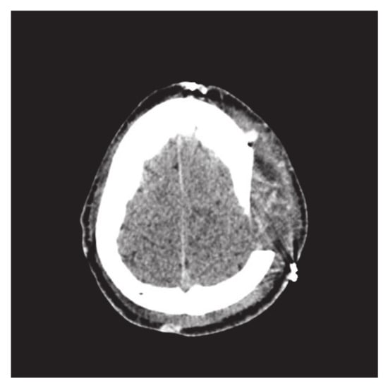
Figure 10.
Parietal bone fracture.
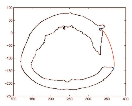
Figure 11.
Construction of fractured part curve using rational Ball curves.
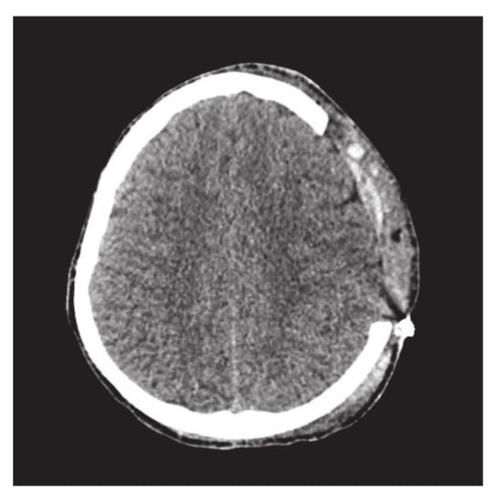
Figure 12.
CT scan image of slice 170.
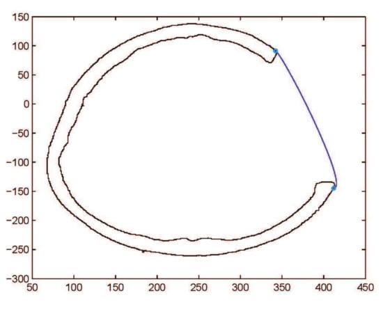
Figure 13.
Construction of fractured part curve using rational Ball curves.
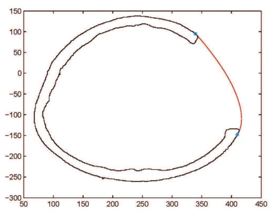
Figure 14.
Construction of fractured part curve using rational Ball curves.
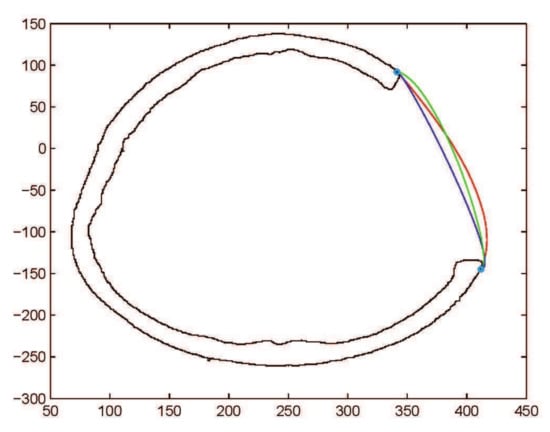
Figure 15.
Comparison of , rational Ball curves (purple and green curves are constructed using and red curve is constructed using
To check the validity of and curves, they are applied to construct the comparatively bigger fractured part, as shown in Figure 16. The results of curve fitting using , curves show the rigidity of the curve resulting in limitation of these methods, as shown in Figure 17, Figure 18 and Figure 19. By dividing the fractured part into segments, the curve become smoother and flexible. The flexibility and smoothness is totally dependent on the number of segments of the fractured part. However, by increasing the number of segments, the required number of control points and and shape parameters are also increased, which is not easy to handle and increases the computational cost.
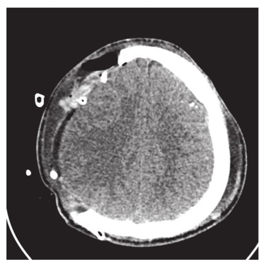
Figure 16.
CT scan slice with big fractured part.
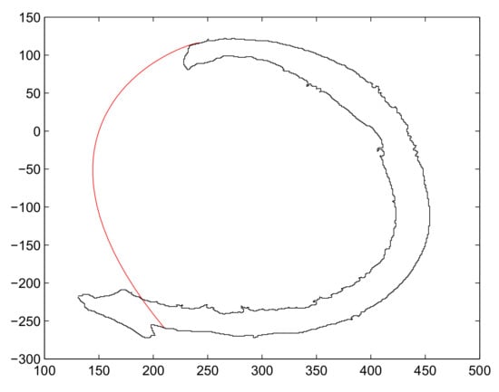
Figure 17.
Construction of fractured part curve using rational Ball curves with one segments.
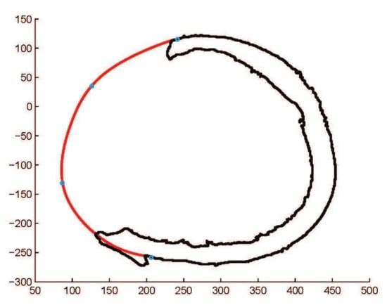
Figure 18.
Construction of fractured part curve using rational Ball curves with three segments.
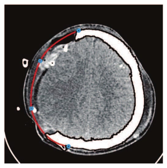
Figure 19.
Construction of fractured part curve using rational Ball curves with three segments.
To reduce the number of control points and overcome the computational cost, cubic B-spline is used to restore the cranial implant. It is very user friendly, one can get the desired curve just clicking on the CT scan image and there is no need to tackle shape parameters, as shown in Figure 20. Using the B-spline curve, there is no need to define and generate the continuity condition between two segments, in contrast to and where the continuity has to be generated. The main controlling tool in the B-spline curve is the knot points; one can change and adjust the curve using knot points. In order to make more flexible and smooth NURBS curves, it has been used for fracture reconstruction, as shown in Figure 21. The NURBS curve is a modified form of the B-spline and is more flexible due to the presence of weights.
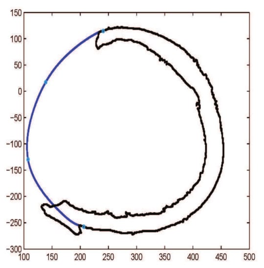
Figure 20.
Construction of fractured part curve using B-spline curves with three segments.
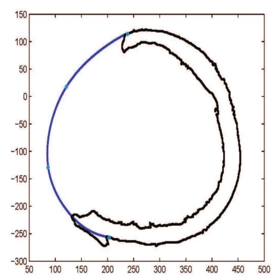
Figure 21.
Construction of fractured part curve using NURBS curve with three segments.
The , rational Ball, B-spline and NURBS curves have been employed on the same image, as shown in Figure 22. The fractured part curves are constructed with three segments. The curve needs 9 free shape parameters and 10 control points. The curve needs 12 free shape parameters and 10 control points. The B-spline curve needs only 6 control points and in the last NURBS curve, needs 6 control points and 6 weights. Table 2 shows the comparison of all parameters and computational time used in Figure 22. Table 3 gives the comparison of different curves used for the construction of craniofacial fractures.

Figure 22.
Pink curve from , green curve from , black curve from B-spline and blue curve from NURBS curve.
Table 2.
Comparison of spline curves with three curve segments.
Table 3.
Comparison of cubic Bézier-like, B-Spline and NURBS curve.
4. Conclusions
The existing techniques for the construction of craniofacial fractures gives effective solutions in different contexts. However, techniques based on spline curves give more advantages by being non-dependent on the reference skull, mirroring and external help. Different Bézier-like functions have been used for the construction of craniofacial fractures and analyzed in detail. Cubic Ball curves with , and continuity worked well for the small fractured part. Using this method, any type of fracture can be constructed and applied on the frontal and parietal bone fractures successfully. The constructed fracture is flexible due to the presence of shape parameters. The computational cost will be high if it will be used for large fractures. To overcome this problem, B-spline and NURBS curves can be used.
Author Contributions
Conceptualization, A.M., M.A. and K.T.M.; Formal analysis, A.M., M.A. and K.T.M.; Funding acquisition, K.T.M.; Methodology, A.M., M.A. and K.T.M.; Software, A.M., M.A. and K.T.M.; Visualization, A.M., M.A. and K.T.M.; Writing—original draft, A.M., M.A. and K.T.M.; Writing—review and editing, A.M., M.A. and K.T.M. All authors equally contributed to this work. All authors have read and agreed to the published version of the manuscript.
Funding
This research received no external funding.
Institutional Review Board Statement
Not applicable.
Informed Consent Statement
Not applicable.
Data Availability Statement
Not applicable.
Acknowledgments
This research was supported by the Department of Mechanical Engineering, Shizuoka University, Hamamatsu, 432-8561 Shizuoka, Japan. The authors are also grateful to the anonymous referees for their valuable suggestions that significantly improved this manuscript.
Conflicts of Interest
The authors declare that they have no conflict of interest to report regarding the present study.
References
- Majeed, A.; Abbas, M.; Miura, K.T.; Kamran, M.; Nazir, T. Surface modeling from 2D contours with an application to craniofacial fracture construction. Mathematics 2020, 8, 1246. [Google Scholar] [CrossRef]
- Eufinger, H.; Wehmöller, M.; Machtens, E.; Heuser, L.; Harders, A.; Kruse, D. Reconstruction of craniofacial bone defects with individual alloplastic implants based on cad/cam-manipulated ct-data. J. Cranio-Maxillofac. Surg. 1995, 23, 175–181. [Google Scholar] [CrossRef]
- Müller, A.; Krishnan, K.G.; Uhl, E.; Mast, G. The application of rapid prototyping techniques in cranial reconstruction and preoperative planning in neurosurgery. J. Craniofac. Surg. 2003, 14, 899–914. [Google Scholar] [CrossRef] [PubMed]
- Majeed, A.; Abbas, M.; Qayyum, F.; Miura, K.T.; Misro, M.Y.; Nazir, T. Geometric modeling using new Cubic trigonometric B-Spline functions with shape parameter. Mathematics 2020, 8, 2102. [Google Scholar] [CrossRef]
- Sauret, V.; Linney, A.D.; Richards, R. Computer assisted surgery: The use of digital images in enabling computerized design and manufacture of titanium implants. Imaging 2002, 14, 464–471. [Google Scholar] [CrossRef]
- Min, K.J.; Dean, D. Highly accurate cad tools for cranial implants. In Proceedings of the 6th International Conference on Medical Image Computing and Computer-Assisted Intervention-MICCAI 2003, Montréal, QC, Canada, 15–18 November 2003; Randy, E.E., Terry, M.P., Eds.; Springer: Berlin/Heidelberg, Germany, 2003; pp. 99–107. [Google Scholar]
- Wu, T.; Engelhardt, M.; Fieten, L.; Popovic, A.; Radermacher, K. Anatomically constrained deformation for design of cranial implant: Methodology and validation. In Proceedings of the 9th International Conference on Medical Image Computing and Computer-Assisted Intervention–MICCAI 2006, Copenhagen, Denmark, 1–6 October 2006; Rasmus, L., Mads, N., Jon, S., Eds.; Springer: Berlin/Heidelberg, Germany, 2006; pp. 9–16. [Google Scholar]
- Shui, W.; Zhou, M.; Deng, Q.; Wu, Z.; Duan, F. 3D craniofacial reconstruction using reference skull-face database. In Proceedings of the 25th International Conference on Image and Vision Computing New Zealand (IVCNZ), Queenstown, New Zealand, 8–9 November 2010; pp. 1–7. [Google Scholar]
- Miyasaka, S.; Yoshino, M.; Imaizumi, K.; Seta, S. The computer-aided facial reconstruction system. Forensic Sci. Int. 1995, 74, 155–165. [Google Scholar] [CrossRef]
- Lee, T.Y.; Sum, Y.N.; Lin, Y.C.; Lin, L.; Lee, C. Three-dimensional facial model reconstruction and plastic surgery simulation. IEEE Trans. Inf. Technol. Biomed. 1999, 3, 214–220. [Google Scholar] [CrossRef] [PubMed]
- Majeed, A.; Mt Piah, A.R.; Gobithaasan, R.U.; Yahya, Z.R. Craniofacial Reconstruction Using Rational Cubic Ball Curves. PLoS ONE 2015, 10, e0122854. [Google Scholar] [CrossRef] [PubMed]
- Majeed, A.; Mt Piah, A.R.; Yahya, Z.R.; Abdullah, J.Y.; Rafique, M. Construction of occipital bone fracture using B-spline curves. Comput. Appl. Math. 2018, 37, 2877–2896. [Google Scholar] [CrossRef]
- Majeed, A.; Mt Piah, A.R. Maxillofacial Fracture Reconstruction Using GC2 Rational Cubic Ball Curves. In Proceedings of the 13th International Conference on Computer Graphics, Imaging and Visualization (CGiV), Beni Mellal City, Morocco, 29 March–1 April 2016; pp. 40–44. [Google Scholar]
- Majeed, A.; Rafique, M.; Abdullah, J.Y.; Rajion, Z.A. NURBS curves with the application of multiple bones fracture reconstruction. Appl. Math. Comput. 2017, 315, 70–84. [Google Scholar] [CrossRef]
- Archer, K.M. Craniofacial Reconstruction Using Hierarchical B-Spline Interpolation. Master’s Thesis, McGill University, Montreal, QC, Canada, 25 August 1997. [Google Scholar]
- Archer, K.M.; Coughlan, K.; Forsey, D.; Struben, S. Software tools for craniofacial growth and reconstruction. In Proceedings of the Graphics Interface, Vancouver, BC, Canada, 18–20 June 1998; pp. 73–81. [Google Scholar]
- Kang, L. Research on the Technique of Face Modeling Based on Skeletal Remains and Appliance to Forensic Facial Reconstruction. Master’s Thesis, Northwest University, Xi’an, China, 2006. [Google Scholar]
- Shui, W.; Zhou, M.; Wu, Z.; Deng, Q. An improved algorithm for craniofacial reconstruction based on landmarks registration. In Proceedings of the 2010 International Conference on Computer Application and System Modeling (ICCASM 2010), Taiyuan, China, 22–24 October 2010; Volume 5, pp. 498–502. [Google Scholar]
- Suetens, P.; Willems, G.; Vandermeulen, D.; De Greef, S.; Claes, P. Statistically deformable face models for cranio-facial reconstruction. J. Comput. Inf.-Technol. 2006, 1, 21–30. [Google Scholar]
- Turner, W.; Brown, R.; Kelliher, T.; Tu, P.; Taister, M.; Miller, K. A novel method of automated skull registration for forensic facial approximation. Forensic Sci. Int. 2005, 154, 149–158. [Google Scholar] [CrossRef] [PubMed]
- Claes, P.; Vandermeulen, D.; De Greef, S.; Willems, G.; Suetens, P. Craniofacial reconstruction using a combined statistical model of face shape and soft tissue depths: Methodology and validation. Forensic Sci. Int. 2006, 159, S147–S158. [Google Scholar] [CrossRef] [PubMed]
- Carr, J.C.; Beatson, R.K.; Cherrie, J.B.; Mitchell, T.J.; Fright, W.R.; McCallum, B.C.; Evans, T.R. Reconstruction and representation of 3D objects with radial basis functions. In Proceedings of the 28th Annual Conference on Computer Graphics and Interactive Techniques (SIGGRAPH’01), Los Angeles, CA, USA, 12–17 August 2001; pp. 67–76. [Google Scholar]
- Majeed, A.; Mt Piah, A.R.; Ridzuan, Y.Z. Surface Reconstruction from Parallel Curves with Application to Parietal Bone Fracture Reconstruction. PLoS ONE 2016, 11, e0149921. [Google Scholar] [CrossRef] [PubMed]
- Ali, J.M. An alternative derivation of said basis functions. Sains Malays. 1994, 23, 42–56. [Google Scholar]
- Ball, A.A. Consurf. part one: Introduction of the conic lofting tile. Comput. Aided Des. 1974, 6, 243–249. [Google Scholar] [CrossRef]
- Farin, G.; Josef, H.; Myung-Soo, K. Handbook of Computer Aided Geometric Design; Elsevier: Boston, MA, USA; London, UK; New York, NY, USA, 2002. [Google Scholar]
- Timmer, H.G. Alternative representation for parametric cubic curves and surfaces. Comput. Aided Des. 1980, 12, 25–28. [Google Scholar] [CrossRef]
- Majeed, A.; Yahya, Z.R.; Mt Piah, A.R.; Ahmad, M.Z. Reconstruction of Craniofacial Image using GC1 Cubic Ball Curves. Indian J. Sci. Technol. 2015, 8, 1–7. [Google Scholar] [CrossRef][Green Version]
Publisher’s Note: MDPI stays neutral with regard to jurisdictional claims in published maps and institutional affiliations. |
© 2022 by the authors. Licensee MDPI, Basel, Switzerland. This article is an open access article distributed under the terms and conditions of the Creative Commons Attribution (CC BY) license (https://creativecommons.org/licenses/by/4.0/).