Article

Evaluation of Liner Cavitation Potential through Piston Slap and BEM Acoustics Coupled Analysis

School of Mechanical Engineering and Automation, Northeastern University, Shenyang 110819, China
*
Author to whom correspondence should be addressed.
Mathematics 2022, 10(6), 853; https://doi.org/10.3390/math10060853
Submission received: 21 January 2022 / Revised: 21 February 2022 / Accepted: 25 February 2022 / Published: 8 March 2022

Abstract

:
Internal combustion engines take up the major position in the power facility market and still encounter some challenges; one key issue is liner cavitation erosion. The impact vibration between piston and cylinder generates pressure fluctuation on the wet liner surface and leads to the occurrence of cavitation in the case that coolant pressure falls below its vapor pressure. Piston slap methodology has been improved by considering the dynamic characteristics of the piston. Water coolant passage acoustic features were investigated and the Helmholtz effect between cylinders was confirmed. In order to address the cavitation erosion potential of the engine cylinder, acoustic pressure in the cooling water passage was investigated by boundary element method analysis with the acceleration of the cylinder liner which was obtained from the piston slap program. This study revealed that a certain acoustic mode of the cooling water passage had a dominant effect on the amplitude of water coolant dynamic pressure induced by liner vibration. Measures of eliminating the acoustic mode are believed to be able to suspend pressure fluctuation and furthermore the potential of cavitation.

1. Introduction

Diesel engines are still in high demand in fields such as transportation and power generation because they are fuel-efficient, have high power density and better response to load changes and are relatively easy to maintain, but there are cases where diesel engines are damaged due to the failure of key component parts, which especially include cylinder head [1], wet liner [2], injection nuzzle [3] and piston ring [4], due to cavitation erosion.
The diesel engines of large output are generally water-cooled four-stroke engines with continuous operation for a long time [5]. In such conditions, cavitation is likely to occur in the water coolant around cylinders, resulting in local concentrated honeycombed pits, especially on the thrust side and antithrust side of liners; this phenomenon is called liner cavitation erosion [6,7]. Cavitation also happens on the other side of liners at the lubricant oil film between piston rings and cylinder liner during the high compression stroke [8]. If left untreated, cavitation erosion would aggravate and finally penetrate the cylinder liner [9], causing catastrophic crack failures, even destroying the sealing of the combustion chamber [10], and require engine overhaul by liner replacement [11]. Though using computing fluid dynamics techniques, the cavitation condition of flowing coolant water can be simulated [12]; at present, it is still hard to predict the occurrence of liner cavitation at the design stage, and the erosion of the outer surface of the cylinder liner is instead usually confirmed in a durability test [13].
Prevention measures of liner cavitation erosion currently being carried out mainly include increasing the static pressure of the coolant system [14], the addition of chemical antifreezing agent to coolant [15] and surface modifications of the liner wet side such as electroless nickel plated gray cast iron [16,17]. The morphology of graphite is found to be a crucial factor of cavitation erosion damage of lamellar gray cast iron [18]. In addition, liner cavitation is known to be initiated by the vibration of cylinder liner, which is basically due to the piston slap phenomenon (piston moves laterally and collides with cylinder liner during reciprocating) [19]. Complex factors between the piston and liner such as clearance [20], pin offset [21] and hydrodynamic lubrication [22] affect liner vibration. Reduction of piston slap is also believed to be able to reduce cavitation [23]. However, even with these measures, the liner cavitation phenomenon can only be eliminated instead of being solved fundamentally. Cylinder liners must be checked regularly, and extra time and cost are required for maintenance [24].
Generally, cavitation is initiated by water coolant pressure fluctuation, which can be evaluated by the pressure condition of the water coolant. The pressure fluctuation is mainly induced by liner vibration which originates from piston secondary motion, and the liner vibration is transmitted from engine structure to water coolant. Therefore, a dynamic model of a piston–liner coupled system is derived to evaluate the cylinder vibration, and the boundary element method is applied to investigate the acoustic features of the water coolant passage; finally, the pressure fluctuation in the cooling water chamber with the acceleration boundary of the vibrating liner can be calculated. The effect of characteristics of the acoustic field on pressure fluctuation is analyzed under different rotation speeds, indicating that a certain acoustic mode of the water coolant passage inspired by engine vibration has an important influence on pressure fluctuation and the potential of cavitation. Current development in this field lacks effective means to evaluate the potential of cavitation during the design stage. The discovery in this paper could be utilized to design coolant passages to suppress certain acoustic modes and therefore the potential of cavitation.

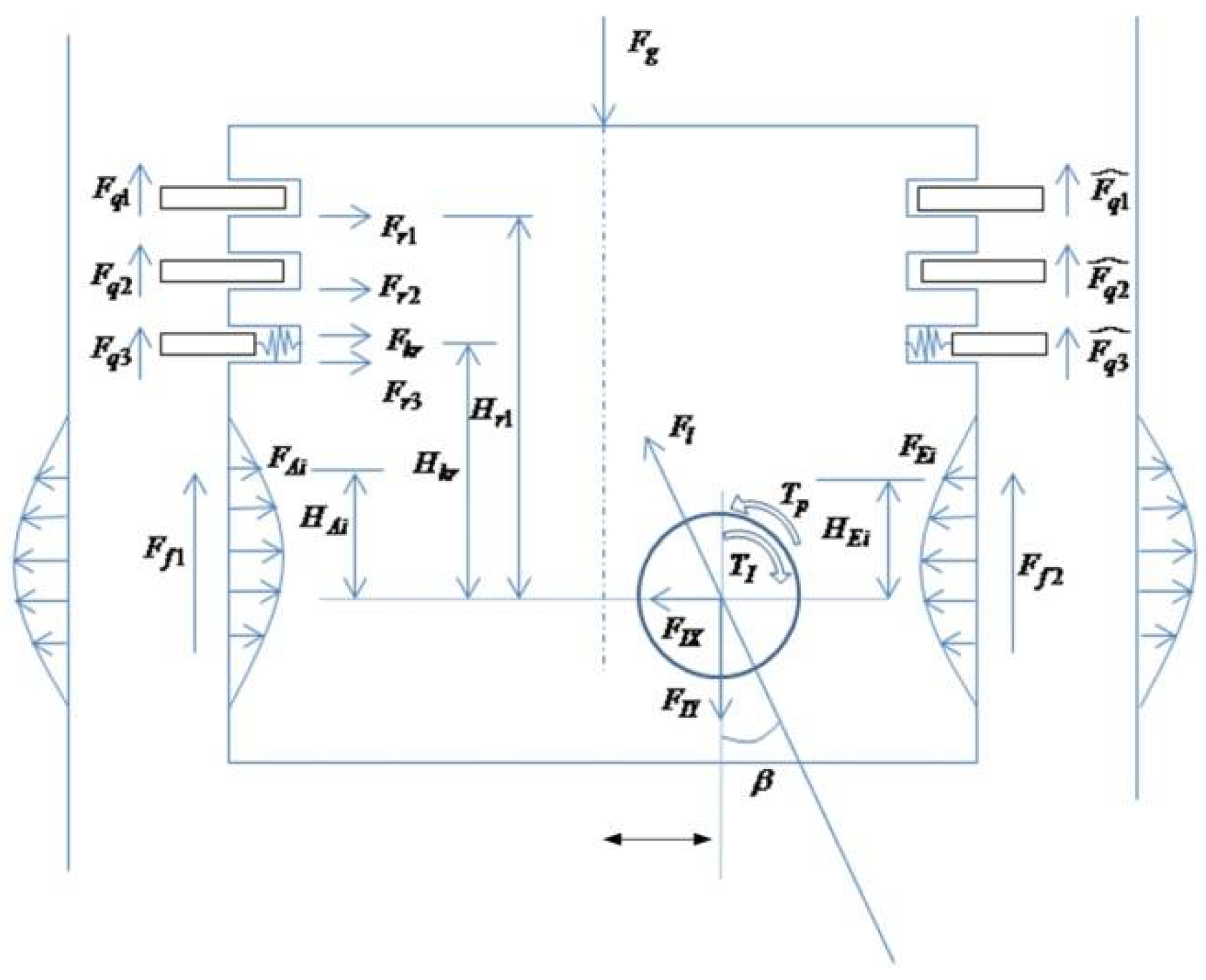
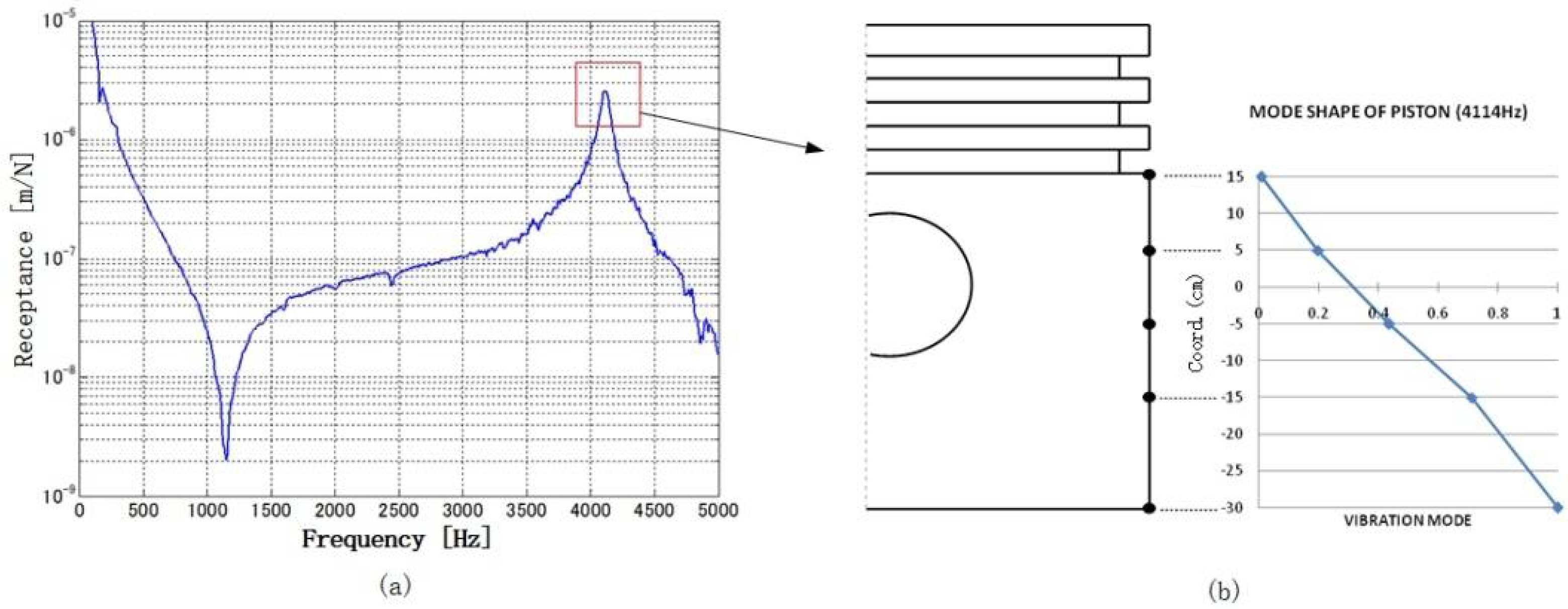
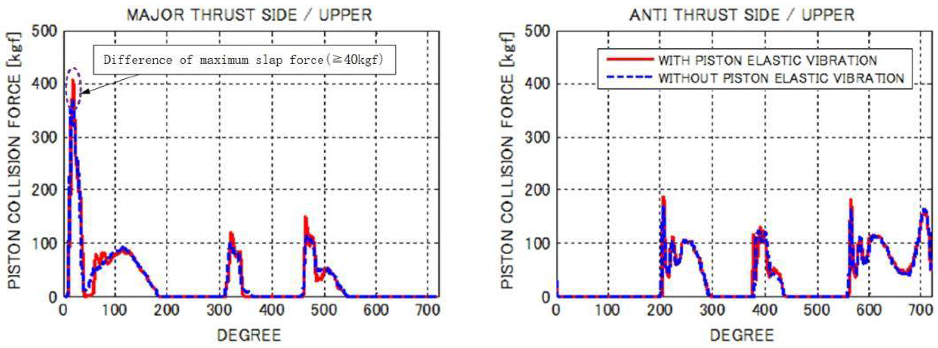
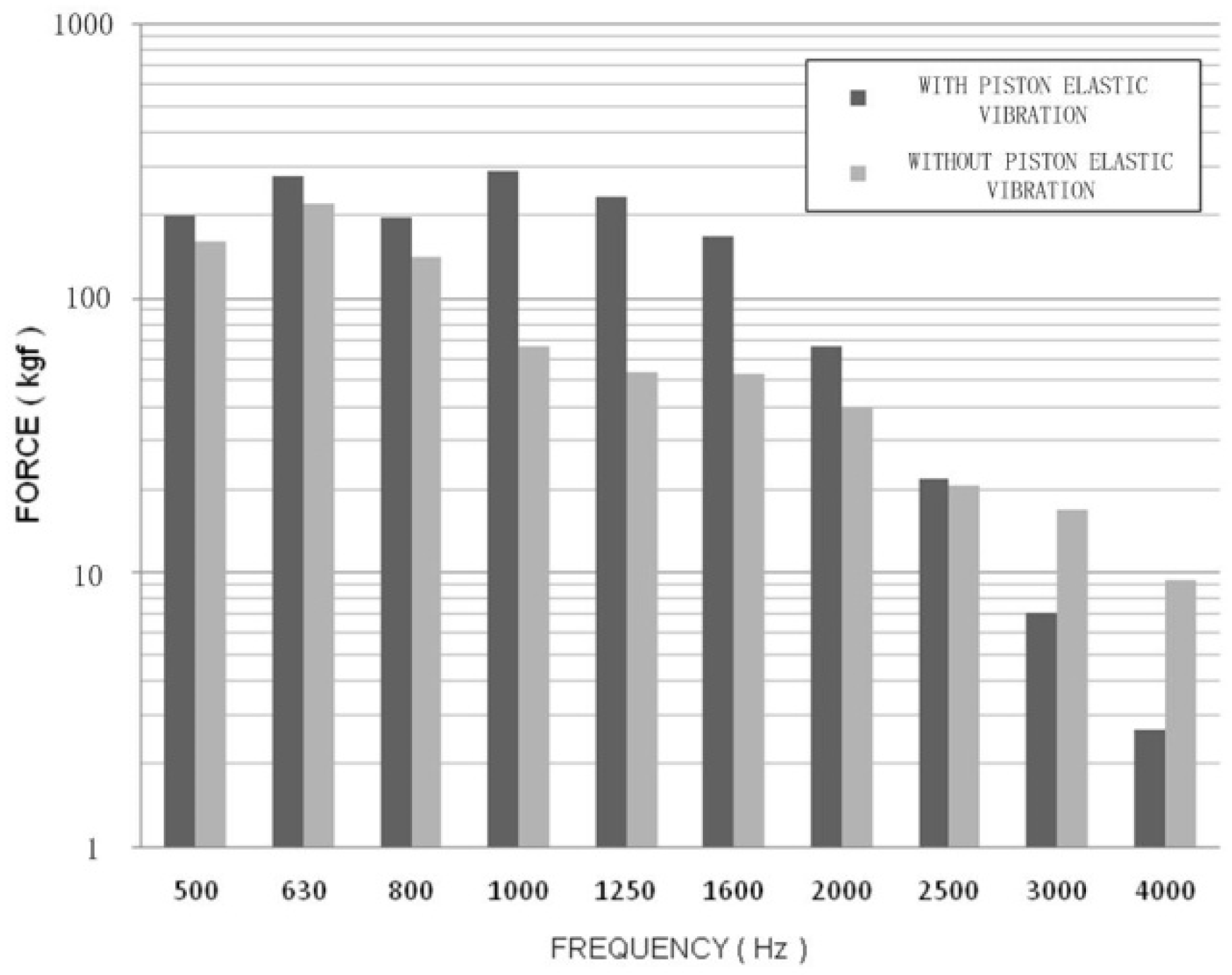
2. Mechanism and Analytical Model of Piston Slap

Piston slap is an important phenomenon of reciprocating combustion engines and may cause liner cavitation and engine noise. It happens when the side force acting on the piston changes. It is crucial to accurately predict slap forces and the corresponding response of engine parts. In this study, a piston slap mechanism has been developed for the prediction of liner vibration acceleration induced by piston slap. A dynamic model of a piston–liner coupled system is derived to calculate the vibration of cylinder liner, taking into account the forces acting on the piston as shown in Figure 1.
[ m p + m r m p ( L y L x tan β ) m p L y I p ] ( X p ¨ θ p ¨ ) = ( f x f θ )
where m p , m r and I p are piston mass, piston ring mass and rotational inertia around the piston pin, respectively. f x and f θ are the lateral force acting on the piston pin and themoment around the pin, respectively, and are expressed by the following expression:
{ f x = F l sinto j = 1 N r F rj + i F Ai i F Ei f θ = m p L x Y ¨ p + T p + F G X po F f 1 ( D 2 + X po ) + F f 2 ( D 2 X po ) + i F Ai i F Ei .
where F l is the connection rod reaction force and F r is the friction force between the piston ring and piston. In order to investigate the vibration response of the liner, we considered the dynamic characteristics of the liner, which are expressed by the following equation:
M ˜ Ln b ¨ n + 2 ζ Ln ω Ln M ˜ Ln b ˙ n + M ˜ Ln ω Ln 2 b n = f ˜ Ln
where M ˜ Ln is the n-th effective mass of the liner, ζ Ln is the n-th effective damping ratio of the liner, ω Ln is the n-th circular frequency of liner and f ˜ Ln is the n-th effective forces acting on the liner. The external force which excites the elastic vibration of the liner originates from the collision between the piston and liner. If the n-th vibration mode of the cylinder liner of collision point j is set to ϕ L ( n , j ) , the effective forces acting on the liner f ˜ Ln areobtained by the following equation:
f ˜ Ln = j ϕ L ( n , j ) F Aj + j ϕ L ( n , j ) F Ej
The equation of motion of the piston–liner system can be derived through the integration between the rigid motion of the piston and the vibration dynamics of the liner, as shown below.
X = ( X p θ p b ) M = [ m p + m r m p ( L y L x t a n β ) 0 m p L y I p 0 0 0 M ˜ L ] C = [ 0 0 0 0 0 0 0 0 2 ζ L n ω L n m ˜ L n ] K = [ 0 0 0 0 0 0 0 0 ω L n 2 m ˜ L n ] F = ( f x f θ f ˜ L n )

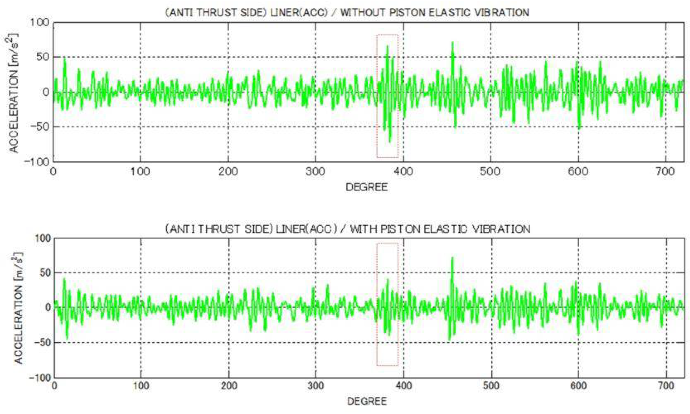
Influence of Elastic Vibration of Piston

Actually, the piston is elastic with dynamic characteristics. The influence of piston elastic vibration on the slapping movement is investigated. Figure 2 shows the frequency response and first vibration mode of the piston skirt, which is measured by the vibration test. The spring coefficients decrease when going toward the bottom of the piston skirt. The main calculation conditions of the piston slap are shown in Table 1.
Figure 3 shows the time history of the slap impact force at thrust and antithrust sides of the piston. The maximum impact force was found arounda crank angle of 15° with elastic vibration of the piston, which is 40 kgf larger than that without elastic vibration mode. From the one-third octave band spectrum of the summation of piston collision forces, as shown in Figure 4, it is inferred that with the effect of elastic vibration of the piston, the total collision force from 1000 to 1600 Hz increases dramatically, whereas in the frequency region of 3000 Hz or more, the total collision force becomes larger without considering the elastic vibration of the piston.
The contour line of collision force distribution at the thrust and antithrust sides of the piston at different crank angles is shown in Figure 5. With the effect of elastic vibration of the piston, there are collision forces at the lower part of the thrust side around the crank angle of 350°. However, without consideration of the elastic vibration of the piston, the collision force at the same position and crank angle is less than 1 kgf. Generally, the collision force at the bottom of the thrust side skirt becomes smaller without consideration of piston elastic vibration.
Figure 6 shows the acceleration waveform at the central part of the liner. When the elastic vibration of the piston is not taken into consideration, there is a large peak near the crank angle of 380° at the antithrust side; comparatively, the acceleration becomes smaller at the same crank angle with consideration of elastic vibration. The collision force distribution contour, as shown in Figure 5, implies that the lower part of the antithrust side of the piston impinges on the liner at the crank angle of 380°, and the collision force without elastic vibration of the piston is larger, which is thought to be the reason forlarger acceleration.
Figure 7 shows the vibration acceleration of the lower end of the thrust side of the piston skirt. The vibration acceleration of the piston skirt is larger near the crankshaft angles of 10, 310, 380 and 450°. According to the impact force waveform in Figure 3 and the impact force distribution in Figure 5, the impact force generated in the lower part of the piston is basically consistent with the acceleration peak, which is due to the larger vibration mode of the lower piston skirt.

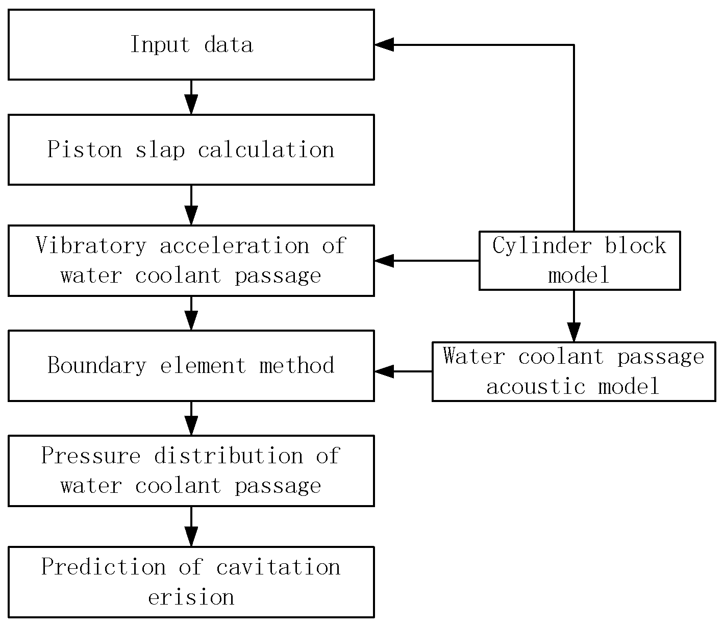
3. Acoustic Pressure Response of Water Jacket Coolant Based on Boundary Element Method

Cavitation is closely related tolocal pressure conditions. In reciprocating engines, the coolant pressure oscillation is mainly induced by slap forces which have been discussed above. The boundary element method is a promising approach for structure–acoustic problems and is widely used in engineering analysis. In this section, the boundary element method (BEM) is applied to calculate the coolant pressure fluctuation. The acoustic field governing equation is represented by the following Helmholtz equation:
2 p + k 2 p = 0 ( k = ω c )
where p is acoustic pressure, k is wave number, ω is circular frequency and c is sound speed. Pressure p and pressure gradient ( p n ) can be expressed as
p = p 0 e j ω t   , p n = jp ω ν = ρ a 0 e j ω t
A second-order differentiable function ϕ is constructed and multiplies Equation (6). The integration of the product in the acoustic domain also equals zero:
V ( 2 p + k 2 p ) ϕ dV = 0
Through Green’s law, Equation (8) can be rewritten as
V ( 2 p + k 2 p ) ϕ dV = V p ( 2 ϕ + k 2 ϕ ) dV + S ( p ϕ n ϕ p n ) dS = 0
where S is the surface of acoustic volume V. ϕ is defined as a fundamental solution of Helmholtz equation which takes the following form in a three-dimensional situation:
ϕ = exp ( ikr ) r
where r is the distance between the observation point and the singularity point on the boundary; ϕ satisfies the following relation:
2 ϕ + k 2 ϕ = 0 , ϕ n = 1 + ikr r 2 r n exp ( ikr )
Combining Equations (7)–(11), the pressure calculation expression is derived as follows:
p = 1 2 π S ( p ϕ n ϕ p n ) dS
The boundary S is dispersed into N elements noted as S 1 , S 2 ,…, S N . The pressure p i of element S j is obtained through summation of the integration of all elements, which indicates the following expression:
p i = 1 2 π j = 1 N S j ( p j ϕ n ϕ p j n ) dS = 1 2 π j = 1 N ( S j ϕ n dS ) p j + 1 2 π j = 1 N ( S j ϕ dS ) p j n
Furthermore, the simplified expression is written as follows:
2 π p i + j = 1 N h ij p j = j = 1 N g ij q j
where
q j = p j n ,   h ij = S j ϕ n dS ,   g ij = S j ϕ dS
The boundary condition of the acoustic field should take into account impendence. Z K is supposed to be the impendence of element S K , which satisfies the following relation:
p k = j ω Z K
Substituting Equation (15) into Equation (14), the following formulation holds:
[ 2 π + h 11 j ω Z Κ h 1 Κ g 1 κ h 1 N h K 1 j ω Z Κ ( 2 π + h KK ) g KK h KN h N 1 j ω Z Κ h N Κ g NK 2 π + h NN ] ( p 1 q K p N ) = [ g 11 g 1 κ g 1 N g K 1 g KK g KN g N 1 g NK g NN ] ( q 1 0 q N )

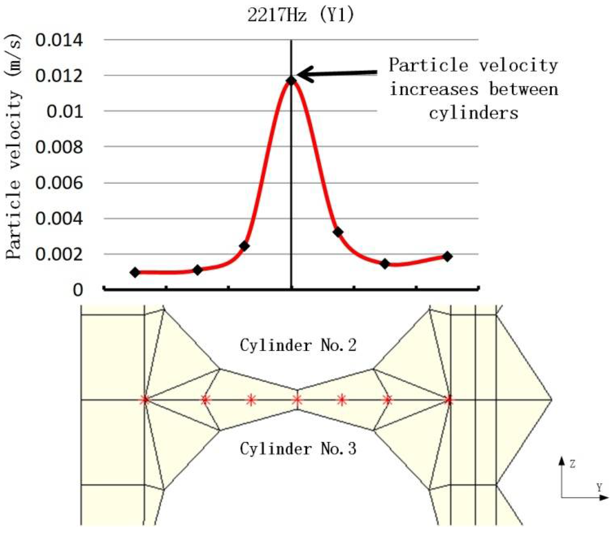
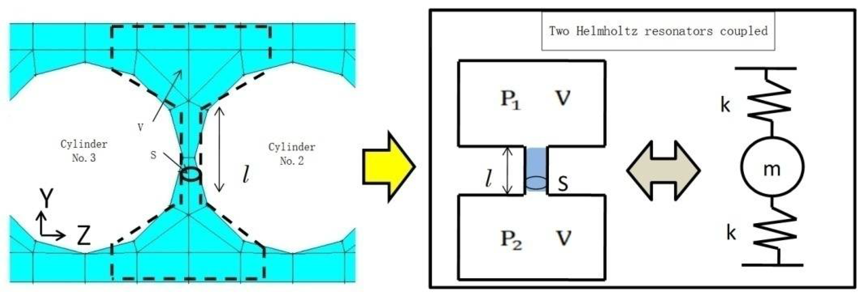
3.1. Water Chamber Acoustic Analytical Model and Its Characteristics

The water jacket is a part of the water cooling system of an engine, which embraces cylinders and dissipates heat. The model of the water jacket used in the analysis is shown in Figure 8. It is extracted from the cylinder block model of a four-cylinder four-cycle diesel engine.
In order to investigate the acoustic characteristics of the water jacket model, a constant acceleration excitation is applied at the center of the No. 2 cylinder with a sweep frequency from 100 to 3000 Hz. Figure 9 shows the frequency response and the corresponding modes of the water jacket model. Blue arrows represent the absolute value of pressure, and color distribution indicates the phase. The figure indicates that there are four resonance frequencies, namely 1513, 2271, 2740 and 2953 Hz, and the corresponding sound pressure distributions are the first mode of Z-axial direction, the first mode of Y-axial direction, the first mode of Z-axial and Y-axial directions combined and the second mode of Z-axial direction. Additionally, we focus on the frequency response characteristics; factors of attenuation (such as impedance boundary) are not considered in this part. Theoretically, the sound pressure at each resonance point diverges to infinity.
In order to further quantify the nature of the water jacket acoustic model, a theoretical rectangular acoustic model is analyzed and compared with the water jacket model. The n-th order of wavenumber k n and natural frequency f n of a rectangular acoustic model with length l 1 , width l 2 and height l 3 can be obtained as follows:
k n = ( k 1 m 1 ) 2 + ( k 2 m 2 ) 2 + ( k 3 m 3 ) 2 ,   f n = k n c 2 π
where c is the sound velocity and k i mi is obtained by the wavenumber of longitudinal waves in each direction.
k i mi = m i π l i ( i = 1 ~ 3 ,   m i = 0 , 1 , 3 , )
The natural frequencies and resonance modes of the water jacket model and theoretical rectangular model are summarized in Table 2. The resonance frequencies of the water jacket model are lower than the theoretical solutions. In particular, the resonance frequency of the Z-axial direction mode is less than half of the theoretical value.
The reason why the resonance frequency of the water jacket model is lower than the theoretical rectangular model without cylinders lies in the Helmholtz effect between cylinders. The particle velocity becomes larger when the particle passes through the narrow gap between the cylinders; therefore, a simple rectangular model cannot predict the acoustic field of the water jacket. In order to investigate the Helmholtz effect between cylinders, we measured the velocity distribution at the resonance frequency (2217 Hz) in the Y-axis direction. Figure 10 shows the distribution of particle velocity (absolute value) in the Y-axis direction between the No. 2 and No. 3 cylinders when the center of the No. 2 cylinder is excited at 2217 Hz (the primary resonance mode in the Y-axial direction). The particle velocity in the gap between cylinders increases and becomes the largest in the middle of the gap. Thus, the large particle velocity in the gap between cylinders lowers the resonance frequency of the primary mode in the Y-axis direction of the water jacket model.
The gap between cylinders is similar to the slot of two Helmholtz resonators facing each other, as shown in Figure 11. The natural frequencies of the Helmholtz resonator can be calculated as
f n = c π S 2 lV
where S   = 6.5 × 10 4   m 2 is the cross-section area of the slot, l   = 50   mm is the length of the slot and V = 3.3 × 10 4   m 2 is the cavity volume. The resonance frequency of the Helmholtz resonator is calculated as 2120 Hz, which is almost equal to the natural frequency of the first mode of the water jacket model. The natural frequency of the resonance mode of the water jacket along thrust direction is greatly influenced by the increased particle speed at the gap between cylinders.

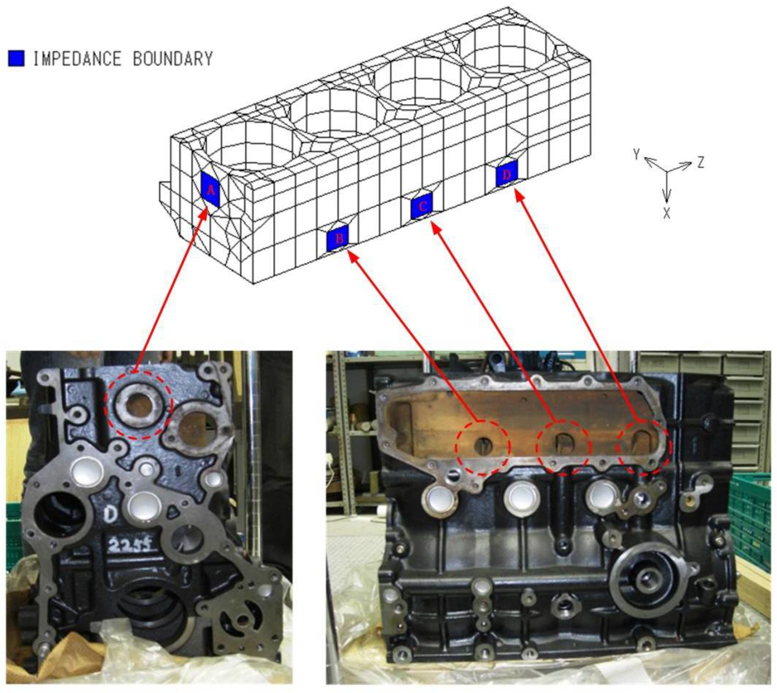
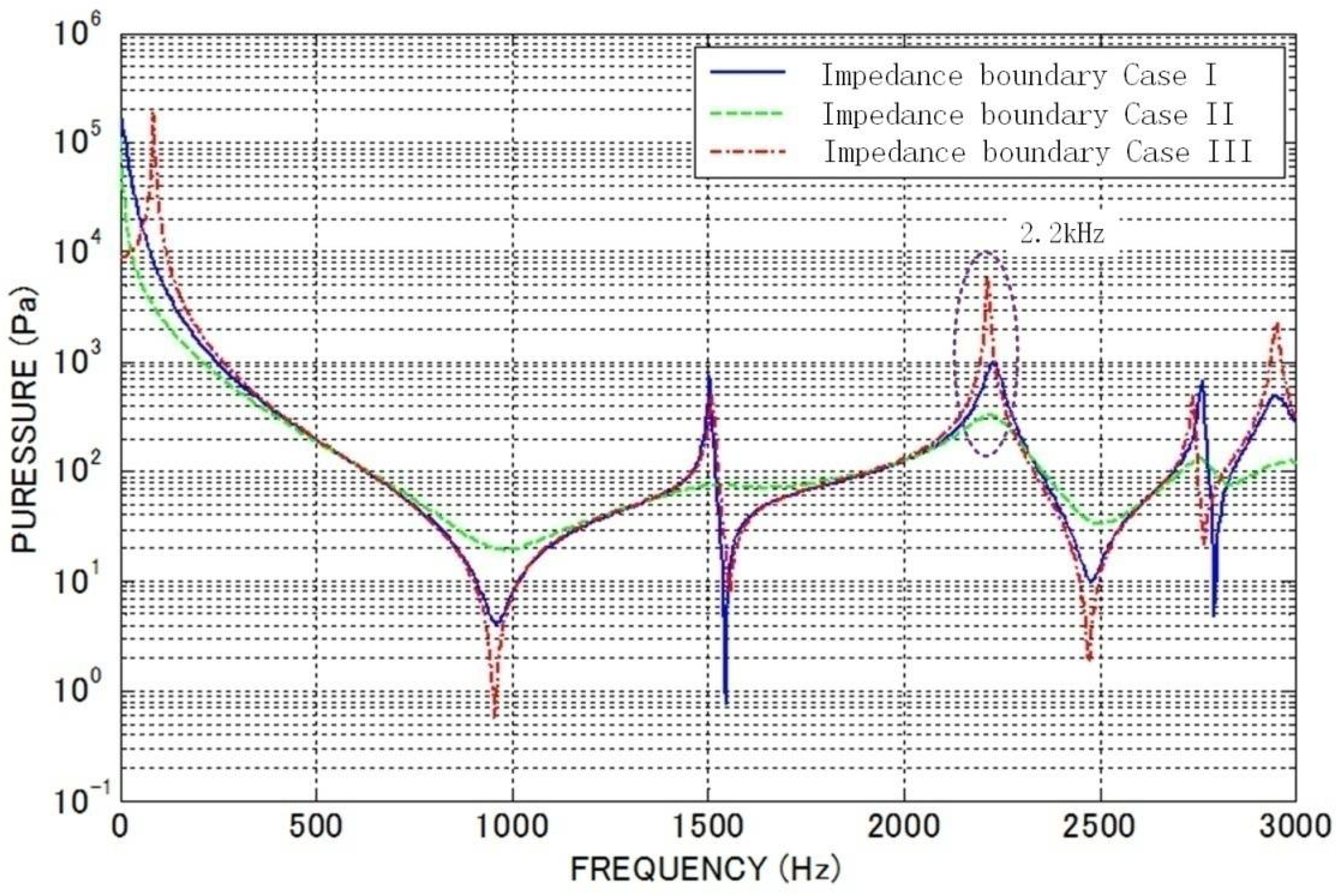
3.2. Acoustic Characteristics of Models with Impedance Boundaries

There are entrances in the water jacket through which coolant water enters and exits, so the impedance of these entrances should be considered. The appearance of the water jacket model with an impedance boundary is shown in Figure 12. The position of the impedance boundary is determined according to the actual engine cylinder block. The impedance value at the boundary is set as z   = 1.5 × 10 6   N s / m 3 .
Figure 13 shows the comparison of the frequency response of three cases: (I) impendence setting at ‘C’, (II) impendence setting at ‘A’ and ‘D’ and (III) without impendence. In the three cases, the resonance frequencies are almost the same. Because of the damping effect, the frequency peaks with impedance are generally smooth compared with the case without impedance. Specifically, the frequency response around 1500 Hz is sharp for case (I), which is thought to be related to the position of impedance boundary. The impedance boundary ‘C’ is located at the center of the water jacket in case (I), and this position is considered to be at the node of 1513 Hz mode in the Z-axial direction, so the energy passing through the impedance boundary is reduced.

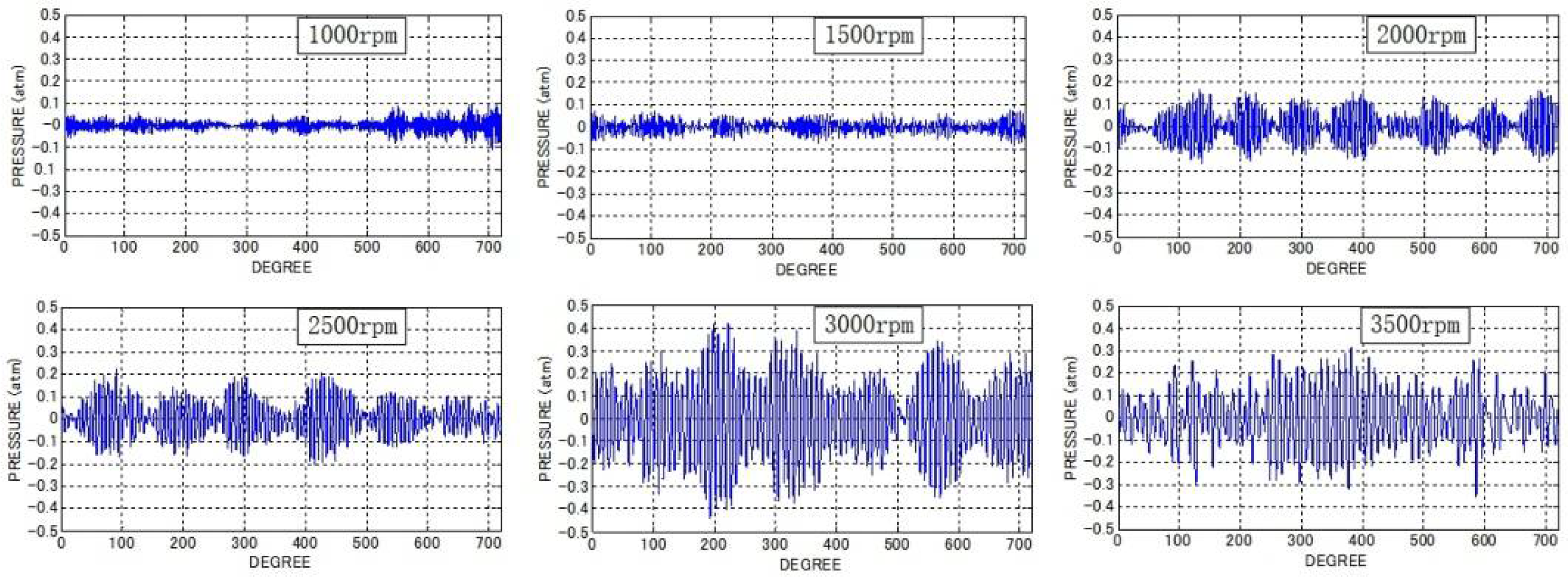
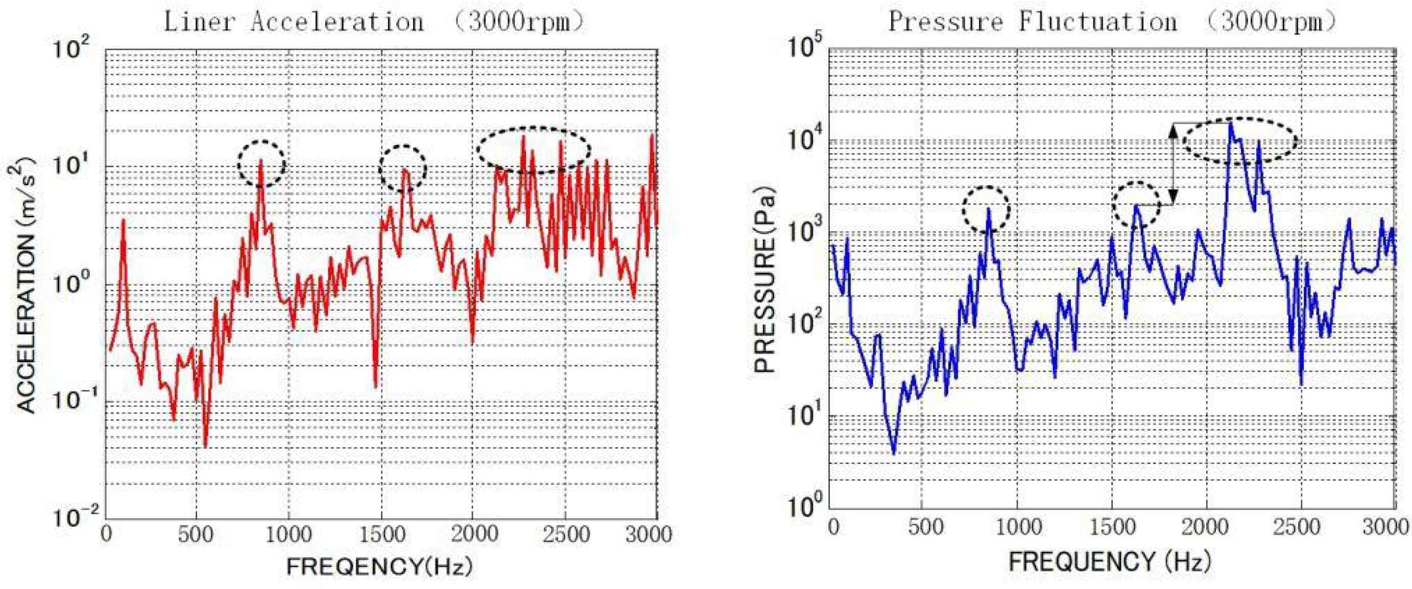
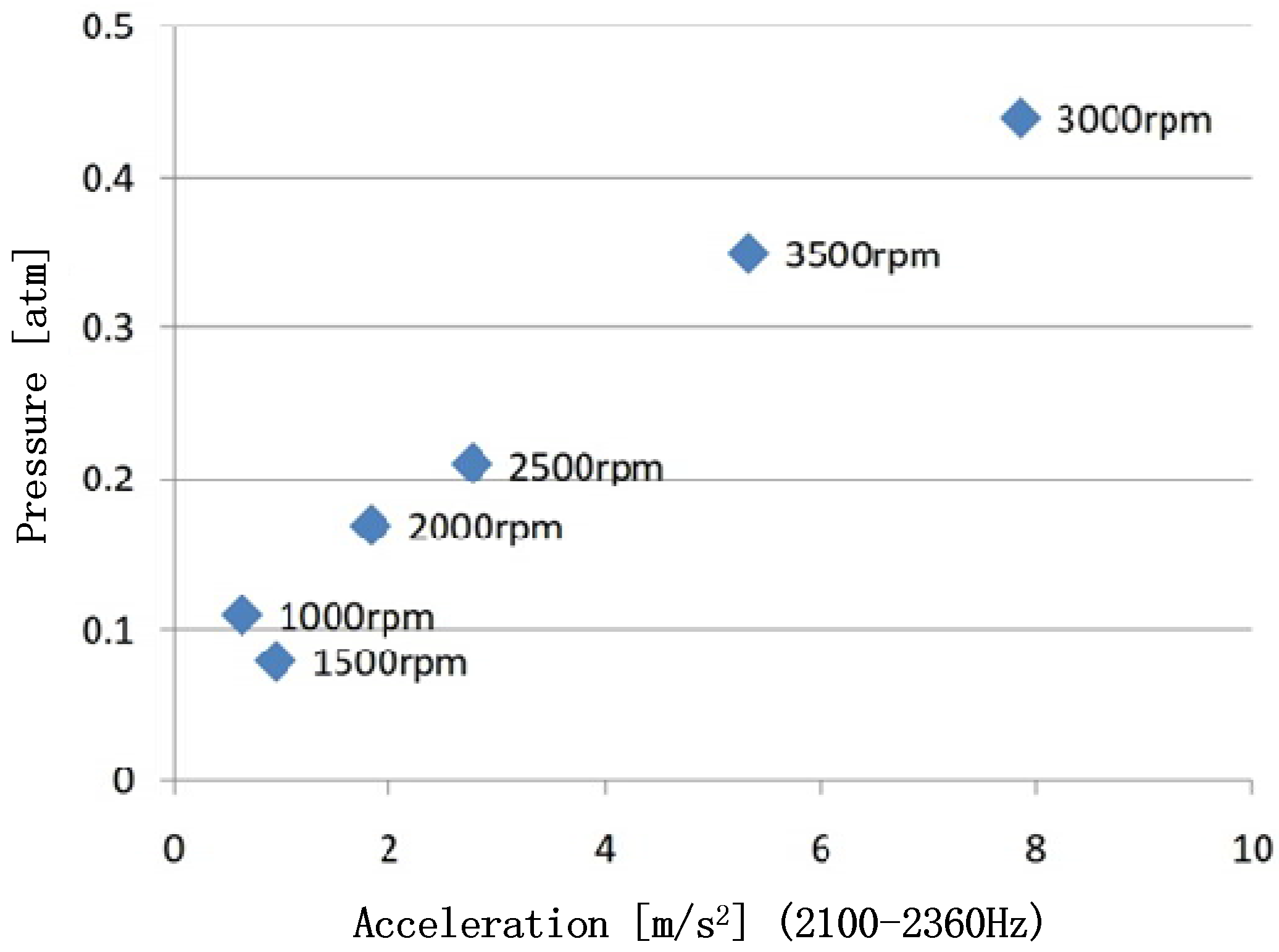
4. Fluctuation of Cooling Pressure Induced by Liner Acceleration at Different Rotation Speeds

A computational method of pressure fluctuation by boundary element method and piston slap theory is proposed as shown in Figure 14. The vibration acceleration of the cylinder liner is calculated by the piston slap program. The vibration acceleration induced by the piston slap is applied on the No. 2 cylinder. With the boundary condition of liner acceleration, pressure fluctuation of the cooling water is investigated by the boundary element method. In addition, the impedance boundary is imported for the damping effect and the remaining boundary is set to be rigid. The calculation condition of the piston slap is the same as Table 1 with different rotation speed.
Pressure fluctuation analysis is carried out by changing the engine speed from 1000 to 3500 rpm. As shown in Figure 15, the pressure amplitude of different revolutions changes dramatically. Figure 16 shows the relationship between engine speed and maximum amplitude of water pressure fluctuations. The pressure amplitude researches maximum at 3000 rpm, and the fluctuation amplitude of cooling water pressure is not proportional to revolution speed. Gradually, the pressure amplitude increases with rotation speed until 3000 rpm then decreases with rotation speed. The underlying reason is that the impact frequency changing with rotation speed affects the water coolant pressure fluctuation.
In order to find the key factors influencing coolant pressure fluctuation, we examine the spectrum of liner acceleration and pressure closely at 3000 rpm. As shown in Figure 17, large frequency components of the liner acceleration spectrum are found around 800 Hz, 1600 Hz and from 2100 to 2700 Hz with nearly the same magnitude. The frequency peaks of the pressure spectrum are similar to the vibration spectrum. However, the component around 2200 Hz stands out and it is nearly 10 times greater than other peaks. The peak frequency of 2200 Hz roughly dominates the amplitude of the time waveform of coolant fluctuating pressure. Such a prominent frequency component is considered to be affected by the acoustic characteristics of the cooling water chamber.
As mentioned in the previous section, the cooling water chamber has an acoustic resonance point at 2217 Hz, which corresponds to the resonant mode in the left and right direction, consistent with the direction of the piston impacting. Therefore, compared with other resonant modes, the 2217 Hz resonant mode has a greater influence.
For the water jacket model of this research, we predict that the pressure of coolant water is influenced by the vibration acceleration component around 2200 Hz. Therefore, the relationship between the vibration acceleration and the amplitude of cooling water pressure is studied. From the spectrum of cylinder liner, we extract the acceleration component from 2100 to 2360 Hz, which overlaps with the resonance frequency of the first acoustic mode in the Y-axial direction. The relationship between the acceleration of a specific frequency band and the maximum pressure fluctuation amplitude at different revolution speeds is drawn in Figure 18, which shows that the distribution is almost linear. In this way, the amplitude of fluctuating pressure of cooling water can be roughly determined by the vibration acceleration of the cylinder overlapped with the resonance frequencies of the water jacket acoustic field.

5. Conclusions

Internal combustion engines have many advantages and are widely used in the transportation and power generation realms, where reliability and durability need special concern. Liner cavitation is one of the serious threats which can cause the breakdown of an engine and require expensive overhaul. The methodology of detecting key factors that affect liner cavitation and therefore predicting cavitation potential is needed to suspend liner cavitation from the design stage. Liner vibration is mainly induced by piston slap, which is believed to initiate liner cavitation, and during the piston collision process, some acoustic characteristics are thought to amplify the pressure fluctuation. Therefore, the piston slap mechanism was proposed and the effect of piston dynamic characteristics on slap forces and liner vibration was investigated. Then, an acoustic model of a water jacket was made and its acoustic characteristics were examined. The natural frequency of the transverse direction mode of the water jacket model was lower than the theoretical solution of the rectangular model, which was due to the increase in particle velocity in the gap between cylinders; the phenomenon was explained through a prototype of two Helmholtz resonators connected face to face. Through the piston slap and boundary element method, we investigated the pressure fluctuation with vibratory acceleration boundary on the cylinder. It was found that the pressure fluctuation of cooling water is influenced not only by the vibration level of the cylinder liner but also by the acoustic characteristics of the water coolant passage, especially the resonance mode of which the direction coincides with the slap forces. Revisions of water coolant passage geometry or boundary conditions for eliminating such an acoustic mode are speculated to be beneficial for suspending coolant pressure. However, liner cavitation is a multiphysics problem that combines not only acoustics and structure dynamics but also fluid dynamics and mechanics of materials. The current research is not sufficient to solve the problem completely. The complexity of the problem requires further investigation considering hydrodynamic cavitation and failure of surface materials, which will be studied in the future.

Author Contributions

Conceptualization, X.W., Z.L. and Q.H.; data collection, H.W. and J.Z.; Formal analysis, S.Z. All authors have read and agreed to the published version of the manuscript.

Funding

This work was supported by the National Natural Science Foundation of China (52005088), Natural Science Foundation of Liaoning Province (2020-MS-076) and National Science and Technology Major Project (J2019-IV-0002-0069).

Institutional Review Board Statement

Not applicable.

Informed Consent Statement

Not applicable.

Data Availability Statement

Not applicable.

Conflicts of Interest

The authors declare no conflict of interest.

References

  1. Fonte, M.; Reis, L.; Infante, V.; Freitas, M. Failure analysis of cylinder head studs of a four stroke marine diesel engine. Eng. Fail. Anal. 2020, 101, 298–308. [Google Scholar] [CrossRef]
  2. Branco, C.M.; Infante, V.; e Brito, A.S.; Martins, R.F. A failure analysis study of wet liners in maritime diesel engines. Eng. Fail. Anal. 2002, 9, 403–421. [Google Scholar] [CrossRef]
  3. Benajes, J.; Pastor, J.V.; Payri, R.; Plazas, A.H. Analysis of the Influence of Diesel Nozzle Geometry in the Injection Rate Characteristic. ASME J. Fluids Eng. 2004, 126, 63–71. [Google Scholar] [CrossRef]
  4. Dellis, P. Laser-induced fluorescence measurements in a single-ring test rig: Evidence of cavitation and the effect of different operating conditions and lubricants in cavitation patterns and initiation. Int. J. Engine Res. 2020, 21, 1597–1611. [Google Scholar] [CrossRef]
  5. Zhou, Y.K.; He, J.G.; Hammitt, F.G. Cavitation erosion of diesel engine wet cylinder liners. Wear 1982, 76, 321–328. [Google Scholar]
  6. Pogodaev, L.I.; Tret’Yakov, D.V.; Valishin, A.G.; Matveevskii, O.O. Simulation of durability of cylinder liners of an internal combustion engine under vibration cavitation. J. Mach. Manuf. Reliab. 2008, 37, 143–151. [Google Scholar] [CrossRef]
  7. Yonezawa, T. A Study on Cavitation Erosion of Cylinder Liner and Cylinder Block. J. Mar. Eng. Soc. Jpn. 1985, 20, 258–264. [Google Scholar] [CrossRef]
  8. Nouri, J.M.; Vasilakos, I.; Yan, Y. Cavitation between cylinder-liner and piston-ring in a new designed optical IC engine. Int. J. Engine Res. 2021, 146808742110080. [Google Scholar] [CrossRef]
  9. Javanmardi, D.; Rezvani, M. Thermomechanical Fracture Failure Analysis of a Heavy-Duty Diesel Engine Cylinder Liner through Performance Analysis and Finite Element Modeling. SAE Int. J. Engines 2020, 13, 665–683. [Google Scholar] [CrossRef]
  10. Fontanesi, S.; Giacopini, M.; Cicalese, G.; Sissa, S.; Fantoni, S. Numerical investigation of the cavitation damage in the wet cylinder liner of a high performance motorbike engine. Eng. Fail. Anal. 2014, 44, 408–423. [Google Scholar] [CrossRef]
  11. Zade, G.; Gadekar, D. Accelerated Simulation of Engine Wet Cylinder Liner Cavitation Test Procedure; SAE Technical Paper 2007-26-023; SAE International: Warrendale, PA, USA, 2007. [Google Scholar]
  12. Zhang, B.; Zhang, P.; Guo, X.; Wang, Y.; Cheng, X.B.; Huang, X.Y.; Gong, X.R. Simulation Research on Cavitation Flow Characteristics of Highly Enhanced Diesel Engine Cooling System. IOP Conf. Ser. Earth Environ. Sci. 2019, 237, 042017. [Google Scholar] [CrossRef]
  13. Steck, B. Avoiding Cavitation on Wet Cylinder Liners of Heavy Duty Diesel Engines by Parameter Changes; SAE Technical Paper 2008-36-0073; SAE International: Warrendale, PA, USA, 2008. [Google Scholar]
  14. Glyniadakis, G.; DAgostini, M.; Casagrande, M. Liner Vibration and Cavitation; SAE Technical Paper 2006-01-2512; SAE International: Warrendale, PA, USA, 2006. [Google Scholar]
  15. Shenoi, S.S.; Sivan, M.; Lakshmikanth, R.; Ganesh, N. Enhancement of Heat transfer of Cylinder liner and Coolant jacket for High powered Diesel engine. Mater. Today Proc. 2020, 24, 1488–1497. [Google Scholar] [CrossRef]
  16. Park, I.; Kim, S. Cavitation Erosion Damage Characteristics of Electroless Nickel Plated Gray Cast Iron. Acta Phys. Pol. A 2019, 135, 1018–1022. [Google Scholar] [CrossRef]
  17. Hutli, E.; Fekete, T.; Nedeljkovic, M. Surface characteristics and cavitation damage progress in ductile materials. Eng. Fail. Anal. 2019, 106, 104157. [Google Scholar] [CrossRef]
  18. Abreu, M.; Sundberg, J.; Elfsberg, J.; Jonsson, S. Morphology and mechanisms of cavitation damage on lamellar gray iron surfaces. Wear 2020, 456–457, 203324. [Google Scholar] [CrossRef]
  19. Zhao, X.; Yang, Z.; Pan, B.; Wang, R.; Wang, L. Analysis of excitation source characteristics and their contribution in a 2-cylinder diesel engine. Measurement 2021, 176, 109195. [Google Scholar] [CrossRef]
  20. Ohta, K.; Wang, X.; Saeki, A. Piston slap induced pressure fluctuation in the water coolant passage of an internal combustion engine. J. Sound Vib. 2016, 363, 329–344. [Google Scholar] [CrossRef]
  21. Xiong, P.; Geng, D.; Hao, G.; Zhang, J.; Guo, W.; Zhao, W.; Chen, L. Influence of piston pin hole offset on cavity erosion of diesel engine cylinder liner. Eng. Fail. Anal. 2019, 103, 217–225. [Google Scholar]
  22. Tian, J.; Feng, H.; Feng, Y.; Yang, Z.; Zhu, C.; Li, J. Piston dynamics analysis considering skirt-liner dynamic clearance. Proc. Inst. Mech. Eng. Part D J. Automob. Eng. 2019, 233, 3538–3553. [Google Scholar] [CrossRef]
  23. Gomboc, S.; Cristofaro, M.; Haramincic, B.; Strucl, J.; Edelbauer, W. Cavitation Erosion Prediction at Vibrating Walls by Coupling Computational Fluid Dynamics and Multi-body-Dynamic Solutions. SAE Int. J. Commer. Veh. 2021, 14, 259–270. [Google Scholar] [CrossRef]
  24. Kim, K.; Hwang, K.; Lee, K.; Lee, K. Investigation of coolant flow distribution and the effects of cavitation on water pump performance in an automotive cooling system. Int. J. Energy Res. 2009, 33, 224–234. [Google Scholar] [CrossRef]
Figure 1. Schematic of force diagram of the piston.
Mathematics 10 00853 g001
Figure 2. Dynamic characteristics of the piston. (a) Measured frequency response of the piston; (b) first elastic mode of the piston.
Mathematics 10 00853 g002
Figure 3. Collision forces of piston with/without dynamic features of the piston.
Mathematics 10 00853 g003
Figure 4. One-third octave band spectrum of the summation of piston collision forces with/without dynamic features of the piston.
Mathematics 10 00853 g004
Figure 5. Distribution of piston slap forces with/without dynamic features of the piston.
Mathematics 10 00853 g005
Figure 6. Vibration acceleration of the central part of the liner with/without dynamic features of the piston.
Mathematics 10 00853 g006
Figure 7. Vibration acceleration of the piston skirt at the lower part of the thrust side.
Mathematics 10 00853 g007
Figure 8. Appearance of water jacket model.
Mathematics 10 00853 g008
Figure 9. Acoustic characteristics of water jacket model.
Mathematics 10 00853 g009
Figure 10. Distribution of particle velocity in Y-axis direction at resonance frequency 2217 Hz.
Mathematics 10 00853 g010
Figure 11. Simplifying the acoustic model between cylinders into a face-to-face Helmholtz coupler.
Mathematics 10 00853 g011
Figure 12. Appearance of water jacket model with impedance boundary.
Mathematics 10 00853 g012
Figure 13. Frequency response curve of water jacket model with different impedance boundaries.
Mathematics 10 00853 g013
Figure 14. Logic flow of calculation.
Mathematics 10 00853 g014
Figure 15. Frequency response curves of water jacket models with different impedance boundaries.
Mathematics 10 00853 g015
Figure 16. Maximum amplitude of water pressure changing with engine rotation speed.
Mathematics 10 00853 g016
Figure 17. Liner acceleration and coolant pressure spectrum at the revolution speed of 3000 rpm.
Mathematics 10 00853 g017
Figure 18. Relationship between cylinder liner vibration acceleration and cooling water pressure amplitude.
Mathematics 10 00853 g018
Table 1. Calculation conditions of piston slap analysis.
Cycle4
Bore × stroke ϕ 135 × 150
Revolution2200 rpm
Piston natural frequency4114 Hz
Effective mass of piston0.09491 kg
Piston liner clearance10 µm
Table 2. Resonance frequencies and modes of the acoustic model of the water jacket and theoretical rectangular box.
Resonance ModeZ1Y1Z1-Y1Z2
Water jacket1513 Hz2217 Hz2740 Hz2953 Hz
Rectangular box1752 Hz5515 Hz5786 Hz3505 Hz
Publisher’s Note: MDPI stays neutral with regard to jurisdictional claims in published maps and institutional affiliations.

