Article

A Dynamic Analysis of Randomly Oriented Functionally Graded Carbon Nanotubes/Fiber-Reinforced Composite Laminated Shells with Different Geometries

1
Mechanical Engineering Department, Faculty of Engineering, King Abdulaziz University, Jeddah 80204, Saudi Arabia
2
Department of Technology, University Centre of Naama, Naama 45000, Algeria
3
Laboratoire d’Etude des Structures et de Mécanique des Matériaux, Département de Génie Civil, Faculté des Sciences et de la Technologie, Université Mustapha Stambouli, B.P. 305, R.P., Mascara 29000, Algeria
4
Mechanical Design and Production Department, Faculty of Engineering, Zagazig University, Zagazig 44519, Egypt
*
Author to whom correspondence should be addressed.
Mathematics 2022, 10(3), 408; https://doi.org/10.3390/math10030408
Submission received: 10 January 2022 / Revised: 25 January 2022 / Accepted: 25 January 2022 / Published: 27 January 2022

Abstract

:
The present study demonstrates the free vibration behavior of composite laminated shells reinforced by both randomly oriented single-walled carbon nanotubes (SWCNTs) and functionally graded fibers. The shell structures with different principal radii of curvature are considered, such as cylindrical, spherical, elliptical–paraboloid shell, hyperbolic–paraboloid shell, and plate. The volume fraction of the fibers has a linear variation along the shell thickness from layer to layer, while the volume fraction of CNTs is constant in all shell layers and uniformly distributed. The fiber-reinforced elements are distributed with three functions which are V-distribution, O-distribution, and X-distribution in addition to the uniform distribution. A numerical analysis was carried out systematically to validate the proposed solution. A new analytical solution is presented based on the Galerkin approach for shells and is exploited to illustrate the influence of some factors on the free vibration behavior of CNTs/fibe-reinforced composite (CNTs/F-RC) laminated shells, including the distributions and volume fractions, various boundary conditions, and geometrical properties of the reinforcement materials. The proposed solution is shown to be an effective theoretical tool to analyze the free vibration response of shells.

1. Introduction

A functionally graded material (FGM), which is an advanced composite material with a continuous gradation of materials through spatial directions, is broadly employed in various applications, ranging from macroscale (i.e., spacecraft, naval, nuclear structures, etc.) to micro/nano-scale electro-mechanical systems (MEMS/NEMS). Recently, the reinforcement of FGM by carbon nanotubes (CNTs) has been used in order to improve the mechanical, electrical, and thermal properties of composite structures due to the excellent properties of CNTs [1,2]. The characteristics of the CNTs/fiber-reinforced composite structure strongly depend on many factors such as the fractal contents of CNTs/fibers [3,4] and Fiber’s geometry [5].
FG beams, plates, and shells have received substantial attention, and an extensive spectrum of beam and plate theories has been introduced, Boutahar et al. [6]. Shen and Zhang [7] investigated the thermal buckling/postbuckling behavior for supported functionally graded carbon nanotubes-reinforced composite (FG-CNTRC) plates subjected to in-plane temperature variation. Zhu et al. [8] examined the static and vibration behaviors of FG-CNTRC plates using the finite element method with the first order shear deformation plate theory. Alibeigloo [9] developed the 3D thermoelasticity solution for an FG-CNTRC plate embedded in a piezoelectric sensor and actuator layers. Liew et al. [10] presented a review to identify and highlight topics relevant to FG-CNTRC and recent research works. Zhang et al. [11] developed a computational solution for the vibration response of FG-CNTRC thick plates resting on elastic foundations. Phung-Van et al. [12] presented the size-dependent impact on the nonlinear transient dynamic response of FG-CNTRC nonlocal nanoplates under a transverse uniform load in thermal environments. Daikh et al. [13] investigated the static response of simply supported FG-CNTRC nonlocal strain gradient nanobeams under various loading profiles using a hyperbolic higher shear deformation beam theory. He et al. [14] implemented the multi-parameter perturbation method to predict the static and stress distribution of FG thin circular piezoelectric plates. The mechanical response of piezoelectric FG plates via a simple first-order shear deformation theory was studied using the isogeometric analysis method [15] and the generalized finite difference method [16].
Daikh et al. [17] presented the influence of thickness stretching on the mechanical responses of FG-CNTRC nanoplates based on the nonlocal strain gradient theory. Esen et al. [18] studied analytically the vibration time response of an FG-CNTRC nanobeam under moving loads using the Navier Procedure. Employing the finite element method, Karamanli and Vo [19] analyzed the mechanical behavior of carbon nanotube-reinforced composites and graphene nanoplatelet-reinforced composite beams incorporating both normal and shear effects. Karamanli and Aydogdu [20] investigated the dynamic behavior of two directional functionally graded carbon nanotube-reinforced composite plates considering various boundary conditions. Boutahar et al. [6] illustrated the impact of thickness stretching on the bending vibratory behavior of thick FG beams using the refined hyperbolic function shear theory. Daikh et al. [21] examined the static response of sandwich FG nonlocal strain gradient nanoplates rested on variable Winkler elastic foundation based on a new quasi 3D hyperbolic shear theory. Daikh et al. [22] inspected the buckling stability and static response of axially FG-CNTRC plates with temperature-dependent material properties. Rostami and Mohammadimehr [23] determined the dynamic stability and bifurcation of an FG-CNTRC plate under lateral stochastic loads via the classical plate theory. Khadir et al. [24] exploited the four-unknowns quasi-3D theory to analyze the mechanical responses of FG-CNTRC nonlocal strain gradient nanoplates. Babaei et al. [25] studied the vibrational response of thermally pre-/post-buckled FG-CNTRC beams on a nonlinear elastic foundation. Duc and Minh [26] predicted the free vibration behavior of cracked FG-CNTRC plates using the phase field theory and the finite element method. Adhikari and Singh [27] illustrated the geometrical nonlinear dynamic response of the FG-CNTRC plate based on a novel shear strain function using the isogeometric finite element procedure.
For shell structures, Shen [28,29] studied the postbuckling of FG-CNTRC cylindrical shells in thermal environments under axial loads and pressure loads based on a higher order shear deformation theory with a von Kármán-type of kinematic nonlinearity by using the singular perturbation technique. Aragh et al. [30] exploited the 3D elasticity theory to evaluate the vibrations of FG-CNTRC cylindrical panels with two opposite edges simply supported via a semi-analytical solution procedure. Shen [31] studied the torsional postbuckling response of FG-CNTRC cylindrical shells in thermal environments. Mirzaei and Kiani [32] investigated the thermal buckling of temperature-dependent FG-CNTRC conical shells under the assumption of the first order shear deformation shell theory, Donnell kinematic assumptions, and the von Kármán type of geometrical nonlinearity. Thomas and Roy [33] examined the vibration analysis of FG-CNTRC Mindlin shell structures by using finite element modelling. The FG material properties were graded smoothly through the thickness. Pouresmaeeli and Fazelzadeh [34] studied the frequency response of doubly curved FG-CNTRC panels via the first-order shear deformation theory and Galerkin’s method. Shojaee et al. [35] studied the vibration of FG-CNTRC skewed cylindrical panels using a transformed differential quadrature method. Tohidi et al. [36] presented the nonlinear dynamic buckling of an FG-CNTRC cylindrical shell via the modified strain gradient theory (the SGT and the Mori–Tanaka approach). Avramov et al. [37] illustrated analytically the self-sustained vibrations of FG-CNTRC shells under a supersonic flow using the linear piston theory. Aminipour et al. [38] presented the size-dependent wave propagation of FG doubly curved nonlocal nanoshells based on the higher order shear deformation theory.
Ahmadi et al. [39] studied the nonlinear vibration response of stiffened FG double-curved shallow shells exposed to thermal and nonlinear elastic environments under hamonic excitation using the perturbation methodology. Babaei et al. [40] developed a theoretical investigation for the frequency response of thermally pre/post buckled CNTRC pipes using a two-step perturbation method. Chakraborty and Dey [41] and Chakraborty et al. [42] developed a semi-analytical approach to explore the nonlinear stability characteristics of an FG-CNTRC cylindrical shell subjected to combined axial compressive loading and localized heating. Dai et al. [43] studied the mechanical behaviors of a 3D poroelasticity FG-GPLRC open shell resting on a non-polynomial viscoelastic substrate involving friction force and residual stresses. Fares et al. [44] developed a consistent layerwise/zigzag model to analyze the free vibrations of multilayered of FG-CNTRC conical shells using the Galerkin method. Fu et al. [45] investigated the vibration instability of FG-CNTRC laminated conical shells surrounded by elastic foundations using first order shear deformation. Yadav et al. [46] developed a semi-analytical solution for the nonlinear vibrations of FG-CNTRC circular cylindrical shells by a radial harmonic force and viscous structural damping. Mohammadi et al. [47] exploited an isogeometric Kirchhoff–Love shell in free and forced vibration analyses of sinusoidally corrugated FG-CNTRC panels. Cong et al. [48] studied the vibration and nonlinear dynamic responses of a temperature-dependent FG-CNTRC laminated double curved shallow shell with a positive and negative Poisson’s ratio. Babaei [49] investigated analytically the nonlinear vibration and snap-buckling behaviors of FG-CNTRC arches using the perturbation method.
Based on the existing literature, the study of the free vibration behavior of composite laminated shells reinforced by randomly oriented SWCNTs remains unexplored, despite the interest for potential applications with different geometrical shapes such as cylindrical, spherical, elliptical–paraboloid, and hyperbolic–paraboloid shells. This motivated the present study. The volume fraction of fibers has a linear variation along the shell thickness from layer to layer, while the volume fraction of CNTs is constant in all shell layers and uniformly distributed. Three gradation functions, including V-distribution, O-distribution, and X-distribution, in addition to the uniform distribution, are considered. Analytical solutions with the Navier procedure are addressed in detail. The rest of the article will focus on the material and geometrical modelling, the governing equations of motion, and analytical solutions, validation, and parametric studies.

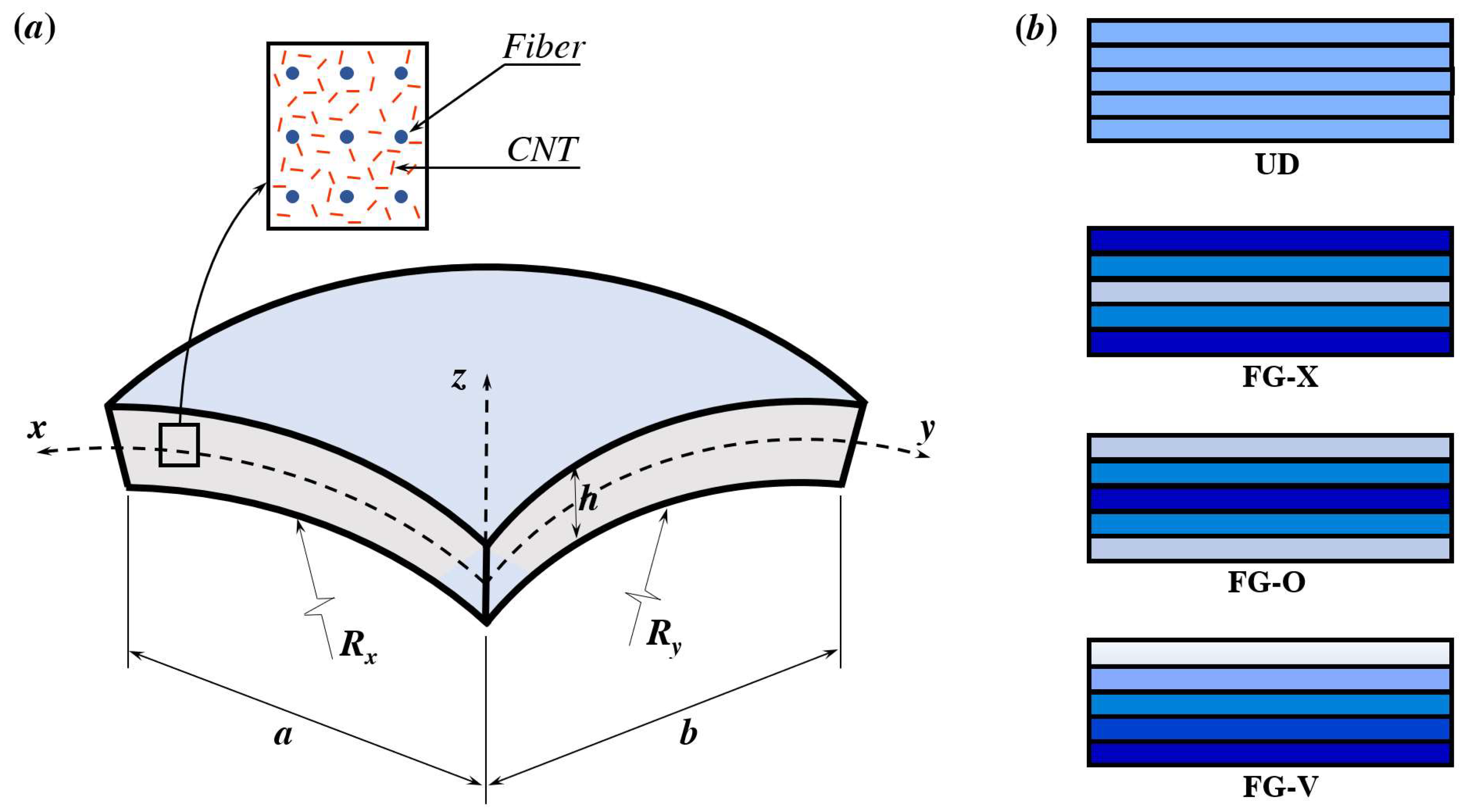
2. Material and Geometrical Modeling

2.1. Mechanical Properties and Geometrics

A rectangular multilayer shell in the Cartesian (x, y, z) coordinate system is shown in Figure 1. The proposed structure has a curved length and width a × b, and thickness h. The principal radii of curvature of the middle plane in the x and y directions are Rx and Ry, respectively. Various forms are analyzed by varying the principal radius of curvature Rx and Ry (See Figure 2). The shell is reinforced by randomly oriented carbon nanotubes (CNTs) and long fibers. All shell layers have the same thickness. The volume fraction of the fibers has a linear variation along the shell thickness from layer to layer, while the volume fraction of CNTs is constant in all shell layers and uniformly distributed. Four different patterns of fiber distribution are created in this study, a uniform distribution UD and three functionally graded distributions FG-X, FG-V, and FG-O.
The effective material properties of the CNTs/fiber-reinforced composite shell were obtained based on a micromechanical model as follows, [50,51]:
E 11 = V f E 11 f + V e f m E e f m
1 E 22 = V f E 22 f + V e f m E e f m V f V e f m v f 2 E e f m E 22 f + ν e f m 2 E 22 f / E e f m 2 v f ν e f m V f E 22 f + V e f m E e f m
1 G 12 = V f G 12 f + V e f m G e f m
υ 12 = V f υ f + V e f m υ e f m
υ 21 = E 22 E 11 υ 21
ρ 12 = V f ρ f + V e f m ρ e f m
Here E , G , ρ , and υ are the Young’s modulus, the shear modulus, the mass density, and Poisson’s ratio, respectively. The subscripts/superscript f and eff and m denote the fibers, the effective material properties, and the matrix, respectively. V f is the volume fraction of fibers and V e f m is the effective volume fraction of the matrix (Polymer/CNTs), where:
V f = 1 V e f m
In the case of the complete random orientation of CNTs throughout the polymer constituent, the composite is considered to be isotropic; therefore, the effective material properties of the mixture of CNTs and polymer can be expressed as:
E e f m = 9 K G 3 K + G
ν e f m = 3 K 2 G 6 K + 2 G
K and G are the effective bulk and shear moduli of the CNT/polymer composite and can be derived by the relations:
K = K p + V c n t ( δ c n t 3 K p α c n t ) 3 ( V p + V c n t α c n t )
G = G p + V c n t ( η c n t 2 G p β c n t ) 2 ( V p + V c n t β c n t )
V p and V c n t are the volume fractions of the polymer and CNTs and are related by:
V p = 1 V c n t
The other parameters appear in the above relations and have the following formulations:
α c n t = 3 ( K p + G p ) + k c n t l c n t 3 ( G p + k c n t )
β c n t = 1 5 ( 4 G p + 2 k c n t + l c n t 3 ( G p + k c n t ) + 4 G p G p + p c n t + 2 ( G p ( 3 K p + G p ) + G p ( 3 K p + 7 G p ) ) G p ( 3 K p + G p ) + m c n t ( 3 K p + 7 G p ) )
δ c n t = 1 3 ( n c n t + 2 l c n t + 2 ( k c n t + l c n t ) ( 3 K p + 2 G p l c n t ) G p + k c n t )
η c n t = 1 5 ( 2 3 ( n c n t l c n t ) + 8 G p p c n t G p + p c n t + 8 m c n t G m ( 3 K p + 4 G p ) 3 K m ( m c n t + G p ) + G p ( 7 m c n t + G p ) + 2 ( k c n t l c n t ) ( 2 G p + l c n t ) 3 ( G p + k c n t ) )
Table 1 presents Hill’s elastic moduli for (10, 10) single-walled carbon nanotubes for various chiral indices.

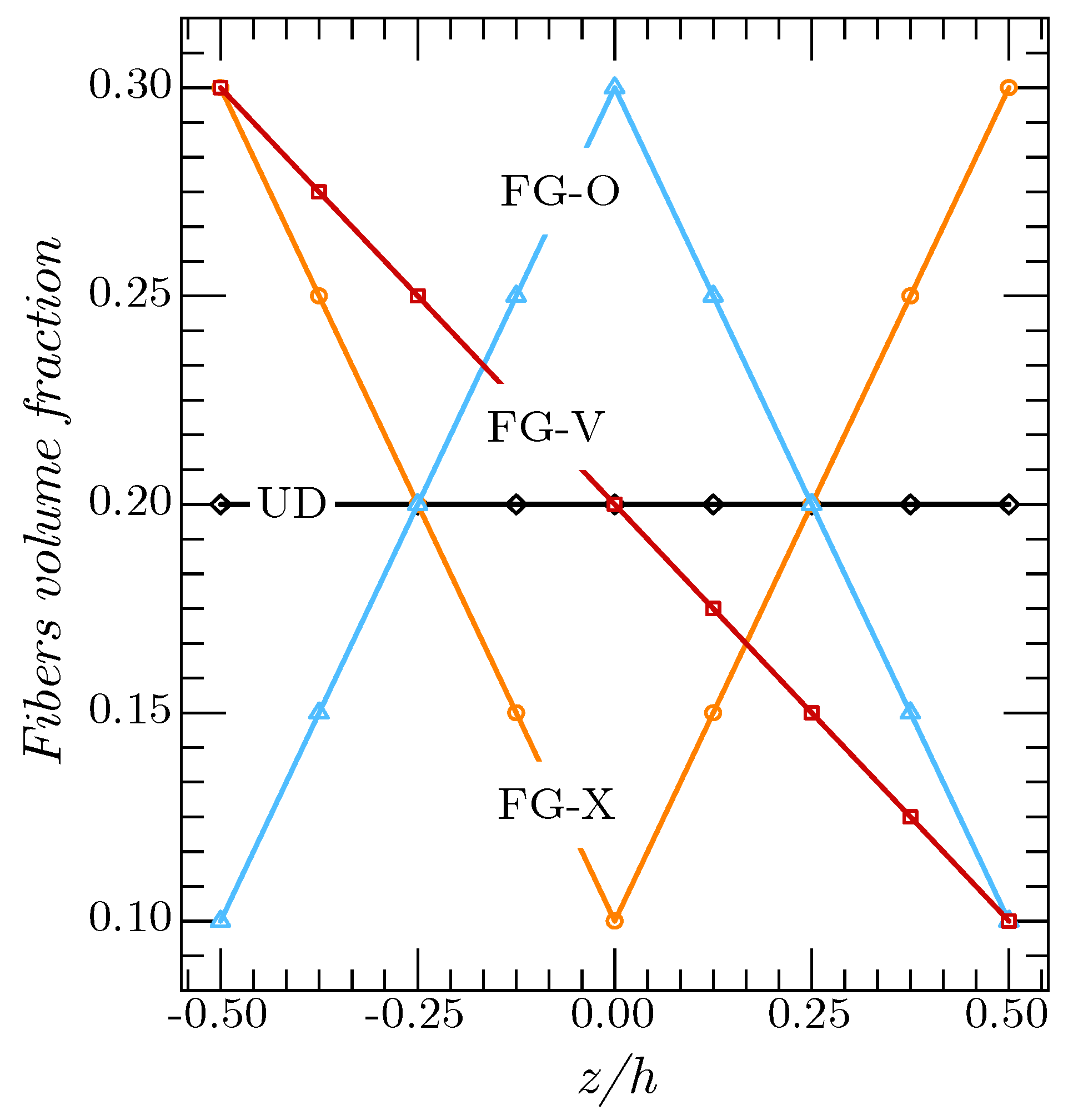
2.2. Volume Fraction of the Reinforcement Fibers

The volume fraction of the fibers for various distribution patterns is expressed as the following relations:
Uniform distribution of the fibers U D f :
V f = V m i n f + ( V m a x f V m i n f ) 2
Functionally graded fiber distribution F G f X :
V f = V m i n f + ( V m a x f V m i n f ) | 2 ( k 1 ) N 1 | N 1
Functionally graded fiber distribution F G f O   :
V f = V m i n f + ( V m a x f V m i n f ) ( 1 | 2 ( k 1 ) N 1 | N 1 )
Functionally graded fiber distribution F G f A   :
V f = V m i n f + ( V m a x f V m i n f ) ( 1 k 1 N 1 )
V m a x f and V m i n f are the maximum and minimum volume fractions of the fibers. N is the number of layers (odd number). The volume fractions along the thickness of the shell for various distribution patterns are plotted in Figure 3.

3. Mathematical Formulations

In the present work, we proposed a hyperbolic sine function shear deformation theory to define the governing equations for the free vibration problem of functionally graded CNTs/fiber-reinforced composite laminated shell. The displacement field can be expressed as:
u ( x , y , z , t ) = ( 1 + z R x ) u 0 z w 0 x + f ( z ) ψ x v ( x , y , z , t ) = ( 1 + z R y ) v 0 z w 0 y + f ( z ) ψ y w ( x , y , z , t ) = w 0
The displacements of the midplane of the composite plate are u 0 , v 0 , and w 0 , whereas ψ x and ψ y are the rotations of the transverse normal at the middle surface z = 0. The shape function f ( z ) is proposed as hyperbolic sine, and it is given as:
f ( z ) = h sinh ( z h ) 3 z 3 2 h 2
where
g ( z ) = f ( z )
The nonzero strains can be determined from the displacement as:
{ ε x x ε y y γ x y } = { ε x x 0 ε y y 0 γ x y 0 } + z { ε x x 1 ε y y 1 γ x y 1 } + f ( z ) { ε x x 2 ε y y 2 γ x y 2 } ε z z = 0 , { γ y z γ x z } = d f ( z ) d z { γ y z 0 γ x z 0 } ,
where:
{ ε x x 0 ε y y 0 γ x y 0 } = { u 0 x + w 0 R x v 0 y + w 0 R y v 0 x + u 0 y } , { ε x x 1 ε y y 1 γ x y 1 } = { 2 w 0 x 2 2 w 0 y 2 2 2 w 0 x y } ,   { ε x x 2 ε y y 2 γ x y 2 } = { φ 1 x φ 2 y φ 2 x + φ 1 y } , { γ y z 0 γ x z 0 } = { φ x φ y } .
The stresses relations associated with the strains can be written as:
{ σ x x σ y y τ y z τ x z τ x y } ( k ) = [ Q ¯ 11 k Q ¯ 12 k 0 Q ¯ 12 k Q ¯ 22 k 0 0 0 0 0 0 0 Q ¯ 44 k 0 0 0 0 0 Q ¯ 55 k 0 0 0 0 0 Q ¯ 66 k ] { ε x x ε y y γ y z γ x z γ x y } ( k )
The transformed material constants Q ¯ i j k are expressed as:
Q ¯ 11 k = Q 11 c o s 4 θ k + 2 ( Q 12 + 2 Q 66 ) s i n 2 θ k c o s 2 θ k + Q 22 s i n 4 θ k Q ¯ 12 k = ( Q 11 + Q 22 4 Q 66 ) s i n 2 θ k c o s 2 θ k + Q 12 ( s i n 4 θ k + c o s 4 θ k ) Q ¯ 22 k = Q 11 s i n 4 θ k + 2 ( Q 12 + 2 Q 66 ) s i n 2 θ k c o s 2 θ k + Q 22 c o s 4 θ k Q ¯ 66 k = ( Q 11 + Q 22 2 Q 12 2 Q 66 ) s i n 2 θ k c o s 2 θ k + Q 66 ( s i n 4 θ k + c o s 4 θ k ) Q ¯ 44 k = Q 44 c o s 2 θ k + Q 55 s i n 2 θ k Q ¯ 55 k = Q 55 c o s 2 θ k + Q 44 s i n 2 θ k
where θ k is the lamination angle of the kth layer:
Q 11 = E 11 1 ν 12 ν 21   ,   Q 22 = E 22 1 ν 12 ν 21 , Q 12 = ν 12 E 22 1 ν 12 ν 21 , Q 44 = G 23 ,   Q 55 = G 13 ,   Q 66 = G 12
By integrating Equation (25), the stress relations, moment, and additional moment resultants can be obtained as:
{ { N } { M } { P } } = [ [ A ] [ B ] [ C ] [ B ] [ D ] [ F ] [ C ] [ F ] [ H ] ] { { ε 0 } { ε 1 } { ε 2 } }
{ R y z R x z } = [ J 44 J 45 J 45 J 55 ] { γ y z 0 γ x z 0 }
where:
{ N } = { N x x N y y N x y } T , { M } = { M x x M y y M x y } T , { P } = { P x x P y y P x y } T { ε 0 } = { ε x x 0 ε y y 0 γ x y 0 } T , { ε 1 } = { ε x x 1 ε y y 1 γ x y 1 } T , { ε 2 } = { ε x x 2 ε y y 2 γ x y 2 } T
The coefficients A i j ,   B i j , D i j , C i j , F i j and H i j are defined as:
{ A i j ,   B i j ,   D i j ,   C i j , F i j , H i j } = n = 1 n h n 1 h n Q i j ( n ) { 1 ,   z , z 2 , f ( z ) , z f ( z ) , f ( z ) 2 } d z ,   ( i , j = 1 , 2 , 6 ) J i i = n = 1 n h n 1 h n Q i i ( n ) [ d f ( z ) d z ] 2 d z , ( i = 4 , 5 )

4. Variational Statements

Hamilton’s principle is employed in this analysis to derive the equations of motion of the CNTs/fiber composite shell:
δ t 2 t 1 δ ( U T + V ) d t   =   0
The variation of the strain energy of the composite shell can be expressed as:
δ U p = 1 2 V [ σ x x ( k ) δ ε x x + σ y y ( k ) δ ε x x + σ x y ( k ) δ γ x y + σ x z ( k ) δ γ x z + σ y z ( k ) δ γ y z ] d V .  
The variation of the kinetic energy of the composite shell at any moment is stated as:
δ T = 1 2 0 L A ρ ( u ˙ δ u ˙ + v ˙ δ v ˙ + w ˙ δ w ˙ ) d A d x
δ T = V { I 0 ( u ˙ 0 δ u ˙ 0 + v ˙ 0 δ v ˙ 0 + w ˙ 0 δ w ˙ 0 ) + I 1 ( w ˙ 0 x δ u ˙ 0 + w ˙ 0 y δ v ˙ 0 + u ˙ 0 δ w ˙ 0 x + v ˙ 0 δ w ˙ 0 y ) + I 2 ( w ˙ 0 x δ w ˙ 0 x + w ˙ 0 y δ w ˙ 0 y ) + I 3 ( φ ˙ x δ u ˙ 0 + u ˙ 0 δ φ ˙ x + φ ˙ y δ v ˙ 0 + v ˙ 0 δ φ ˙ y ) + I 4 ( φ ˙ x δ w ˙ 0 x + w ˙ 0 x δ φ ˙ x + φ ˙ y δ w ˙ 0 y + w ˙ 0 y δ φ ˙ y ) + I 5 ( φ ˙ x δ φ ˙ x + φ ˙ y δ φ ˙ y ) } d x d y d z
where:
{ I 0 ,   I 1 ,   I 2 ,   I 3 , I 4 , I 5 } = n = 1 k ρ ( z ) { 1 ,   z , z 2 , Φ ( z ) , z Φ ( z ) , ( Φ ( z ) ) 2 } d z
By inserting Equations (32)–(34) into Equation (19), the equilibrium equations for a CNTs/fiber composite shell can be obtained as follows:
A 11 2 u 0 x 2 + A 66 2 u 0 y 2 + ( A 12 + A 66 ) 2 v 0 x y + ( A 11 R x + A 12 R y ) w 0 x B 11 3 w 0 x 3 ( B 12 + 2 B 66 ) 3 w 0 x y 2 + B 11 s 2 ψ x x 2 + B 66 s 2 ψ x y 2 + ( B 12 s + B 66 s ) 2 ψ y x y = ( I 0 + 2 I 1 R x + I 3 R y 2 ) 2 u 0 t 2 ( I 1 + I 2 R x ) 3 w 0 x t 2 + ( I 3 + I 4 R x ) 2 ψ x t 2
( A 12 + A 66 ) 2 u 0 x y + A 22 2 v 0 y 2 + A 66 2 v 0 x 2 ( B 12 + 2 B 66 ) 3 w 0 x 2 y B 22 3 w 0 y 3 + ( A 12 R x + A 22 R y ) w 0 x + ( B 12 s + B 66 s ) 2 ψ x x y + B 22 s 2 ψ y y 2 + B 66 s 2 ψ y x 2 = ( I 0 + 2 I 1 R y + I 2 R y 2 ) 2 v 0 t 2 ( I 1 + I 2 R y ) 3 w 0 y t 2 + ( I 3 + I 4 R y ) 2 ψ y t 2
B 11 3 u 0 x 3 + ( B 12 + 2 B 66 ) 3 u 0 x y 2 ( A 11 R x + A 12 R y ) u 0 x + ( B 12 + 2 B 66 ) 3 v 0 x 2 y + B 22 3 v 0 y 3 ( A 12 R x + A 22 R y ) v 0 y + ( 2 B 11 R x + 2 B 12 R y ) 2 w 0 x 2 D 11 4 w 0 x 4 ( 2 D 12 + 4 D 66 ) 4 w 0 x 2 y 2 D 22 4 w 0 y 4 + ( 2 B 12 R x + 2 B 22 R y ) 2 w 0 y 2 ( A 11 R x 2 + 2 A 12 R x R y + A 22 R y 2 ) w 0 + D 11 s 3 ψ x x 3 + ( D 12 s + 2 D 66 s ) 3 ψ x x y 2 ( B 11 s R x + B 12 s R y ) ψ x x + ( D 12 s + 2 D 66 s ) 3 ψ y x 2 y + D 22 s 3 ψ y y 3 ( B 12 s R x + B 22 s R y ) ψ y y = I 0 2 w 0 t 2 + ( I 1 + I 2 R x ) 3 u 0 x t 2 + ( I 1 + I 2 R y ) 3 v 0 y t 2 I 2 ( 4 w 0 x 2 t 2 + 4 w 0 y 2 t 2 ) + I 4 ( 3 ψ x x t 2 + 3 ψ y y t 2 )
B 11 s 2 u 0 x 2 + B 66 s 2 u 0 y 2 + ( B 12 s + B 66 s ) 2 v 0 x y D 11 s 3 w 0 x 3 ( D 12 s + 2 D 66 s ) 3 w 0 x y 2 + ( B 11 s R x + B 12 s R y ) w 0 x + F 11 s 2 ψ x x 2 + F 66 s 2 ψ x y 2 A 44 s ψ x + ( F 12 s + F 66 s ) 2 ψ y x y = ( I 3 + I 4 R x ) 2 u 0 t 2 I 4 3 w 0 x t 2 + I 5 2 ψ x t 2
( B 12 s + B 66 s ) 2 u 0 x y + B 11 s 2 v 0 y 2 + B 66 s 2 v 0 x 2 ( D 12 s + 2 D 66 s ) 3 w 0 x 2 y D 22 s 3 w 0 y 3 + ( B 12 s R x + B 22 s R y ) w 0 x + ( F 12 s + F 66 s ) 2 ψ x x y + F 11 s 2 ψ y y 2 + F 66 s 2 ψ y x 2 A 44 s ψ y = ( I 3 + I 4 R y ) 2 v 0 t 2 I 4 3 w 0 y t 2 + I 5 2 ψ y t 2

5. Analytical Solution

The aim of this work is to expand the use of analytical solutions to analyze the response of various structures such as shells by considering different boundary conditions, as shown in Table 2. Therefore, the Galerkin approach can provide accurate solutions. The expressions of generalized displacements can be expressed as:
{ u 0 , ψ x } = m = 1 n = 1 { U m n , X m n } X m ( x ) x Y n ( y ) e i ω t { v 0 , ψ y } = m = 1 n = 1 { V m n , Z m n } X m ( x ) Y n ( y ) y e i ω t w 0 = m = 1 n = 1 W m n X m ( x ) Y n ( y ) e i ω t
U m n , V m n , X m n , and Z m n are arbitrary parameters. The boundary conditions that can be imposed on all the four boundaries of the CNTs/F-RC shells are given in Table 2 as:
The functions X m ( x ) and Y n ( y ) that satisfy the above boundary conditions are given in Table 3.
By substituting Equation (41) in Equations (36)–(40), one obtains:
[ K ] = [ K 11 K 12 K 13 K 14 K 15 K 12 K 22 K 23 K 24 K 25 K 13 K 23 K 33 K 34 K 35 K 14 K 24 K 34 K 44 K 45 K 15 K 25 K 35 K 45 K 55 ] ,   [ M ] = [ M 11 M 12 M 13 M 14 M 15 M 21 M 22 M 23 M 24 M 25 M 13 M 23 M 33 M 34 M 35 M 14 M 24 M 34 M 44 M 45 M 15 M 25 M 35 M 45 M 55 ]
where [ K ] et [M] are the rigidity matrix and mass matrix, respectively.
The elements K i j and M i j of the matrix [ K ] and [ M ] are given in Appendix A.

6. Results and Discussions

6.1. Verification Analysis

Firstly, to examine the accuracy and effectiveness of the developed model, the results for the free vibration of functionally graded shells were compared with those generated in the literature using various solution techniques (see Table 4). The materials used were Alumina (AlO2) as the ceramic ( E c = 380   GPa , ρ c = 3800   kg / m 3 ) and Aluminium (Al) as the metal ( E m = 70   GPa , ρ c = 2707   kg / m 3 ). Poisson’s ratio was taken as υ = 0.3 . It can be observed that the results computed by the proposed HSDT are absolutely identical to those generated in the literature.

6.2. Parametric Stud

The analyzed composite shell was made of a mixture of the polymer, armchair (10, 10) single-walled CNTs, and long fibers as reinforcements. The material properties of the polymer were [57]: E p = 2.5   GPa , ρ p = 1190   kg / m 3 , and υ p = 0.19 , while the material properties of the fiber were [58]: E 11 f = 233.5   GPa , E 22 f = 23.1   GPa , G 12 f = 8.96   GPa , ρ f = 1750   kg / m 3 , and υ f = 0.2 . The density of the CNTs was assumed to be equal to ρ f = 1400   kg / m 3 . To standardize and simplify calculations, the normalized parameters for the vibration analyses of the CNTs/fiber shells are described using the following forms:
ω ¯ = ω h ρ m E m
In the following analysis, a parametric study on the vibration of CNTs/F-RC shells is carried out. Two types of laminated shells are proposed: cross-ply laminates and unidirectional laminates. For the unidirectional laminates, the angle of the orientation θ was equal to 0°. For the cross-ply laminates, the angle of the orientation θ of each layer changed alternately ( θ = 0° or 90°), for example, in the case of five layers, the shell could be described as [0°/90°/0°/90°/0°] laminate. The effect of the number of layers N and the fiber distribution patterns on the dimensionless frequency of simply supported cross-ply F/CNT-RC shells for various curvature radii was examined as shown in Table 5. The maximum volume fraction was taken as V m a x f = 30 % , while the minimum is V m i n f = 10 % . The volume fraction of the CNTs was taken as V c n t = 1 % . The same analysis is discussed on the unidirectional F/CNT-RC shells in Table 6.
Table 7 shows the impact of the volume fraction and the fiber distribution patterns on the dimensionless frequency of simply supported cross-ply F/CNT-RC laminated shells. The number of layers was fixed at nine (9) layers. It is clear from this table that the change in the volume fraction of the CNTs had a significant influence on the free vibration behaviour of the shells.
The effect of the volume fraction and the distribution patterns of the fibers on the dimensionless frequency of simply supported cross-ply F/CNT-RC shells is demonstrated in Table 8. The volume fraction of the CNTs was proposed as V c n t = 1 % , whereas the minimal volume fraction of the fibers was V m i n f = 0.05 . The increase in the fiber volume fraction further reinforced the composite plate; therefore, the dimensionless frequencies increased.
Table 9 presents the influence of the fiber distribution patterns on the dimensionless frequency of cross-ply F/CNT-RC shells for various boundary conditions. The fully clamped plate (CCCC) had the highest frequencies, while the lowest frequencies were for the simply supported shells, wherever the fiber distribution pattern was.
The action of the geometric parameters a/h and b/a on the dimensionless frequency of simply supported cross-ply F/CNT-RC shells for various curvature radii is tabulated in Table 10. It is observed that the frequencies decreased when the thickness ratio a/h was decreased and the aspect ratio b/a was increased.
Figure 4 shows the the impact of the number of layers “N” on the vibration frequencies of simply supported CNTs/F-RC shells using different fiber distribution patterns. Two types of shells were analyzed: cross-ply fibers and unidirectional fibers. The number of layers “N” changed from 3 to 19. In the case of cross-ply fibers, the increase in the number of layers “N” led to an increment in the dimensionless frequencies. The FG-X fiber distribution shells had the highest frequencies because of their excellent rigidity. In the case of unidirectional fibers, contradictory results were obtained. Precisely, the dimensionless frequencies increased with the increase in the number of layers for the patterns FG-O and FG-B, while the opposite effect was seen for the FG-X patterns. As is known, to increase the rigidity of the structure, it is obligatory to increase the reinforcement materials at the superior and the inferior sheets. On the other hand, the increase in the number of layers meant that the thickness of each layer decreased; therefore, the thickness of the strongest layer (superior and inferior layers) decreased, and this can explain the reduction in the rigidity of the plate. For the case of unidirectional fibers with uniform distribution UD, the number of layers did not have any influence.
Figure 5 shows the variation of dimensionless frequencies in the function of the radii of curvature ( R x / a ) . The radii of curvature R y / b is fixed at inf, 5, and −5. In general, the increase in the radii of curvature R x / a led to a critical decrement in frequencies for the values ( R x / a 5 ) , and then, the frequencies continued to decrease in the cylindrical and the elliptical–paraboloid shells (R/b = inf, 5) slightly, and they increased in the case of the hyperbolic–paraboloid shell (R/b = −5).
In Figure 6, the influences of the volume fraction of fibers and CNTs on the vibration frequencies of simply supported FG-X CNTs/F-RC plate are plotted. The minimal volume fraction of the fibers was V m i n f = 0.05 . It is evident that the increase in the volume fraction of the reinforcement led to an increment in plate stiffness; therefore, the natural frequencies increased. Comparing the two reinforcement materials, the increase in the volume fraction of the CNTs had a more important effect than the volume fraction of the fibers.
The effect of both the aspect ratio b/a and the thickness ratio a/h on the dimensionless frequency of a spherical shell ( R x / a = R y / b = 5 ) for various boundary conditions is demonstrated in Figure 7. The increase in the aspect ratio led to a decrement in the dimensionless frequencies regardless of the boundary condition type. For the thickness ratio a/h effect, the frequencies decreased critically for values a / h 10 . The fully clamped shells had the highest values of frequency, while the lowest values were for the simply supported shells.
Finally, in Figure 8, the effect of the modes of vibration “m” and “n” on the dimensionless frequency of a spherical shell is plotted. We can see that the dimensionless frequency is influenced by mode shapes m and n, where the frequency increased with the increase in the vibrational mode shapes.

7. Conclusions

The free vibration behavior of composite laminated plates and shells reinforced by both randomly oriented (10, 10) single-walled carbon nanotubes (SWCNTs) and functionally graded fibers is presented in this work. Four distribution patterns of fiber reinforcement including UD-distribution, V-distribution, O-distribution, and X-distribution were analyzed. The problem was tackled theoretically based on the Galerkin technique and accounting for different boundary conditions. A parametric study was performed systematically to check for the effect of some significant factors on the free vibration response of CNTs/F-RC laminated shells, namely the fiber reinforcement patterns and the volume fraction of CNTs, together with the geometric parameters of the shells. The results showed that the present solution is in close agreement with the other available solutions in the literature. Based on the parametric investigation, the following concluding remarks are revealed:
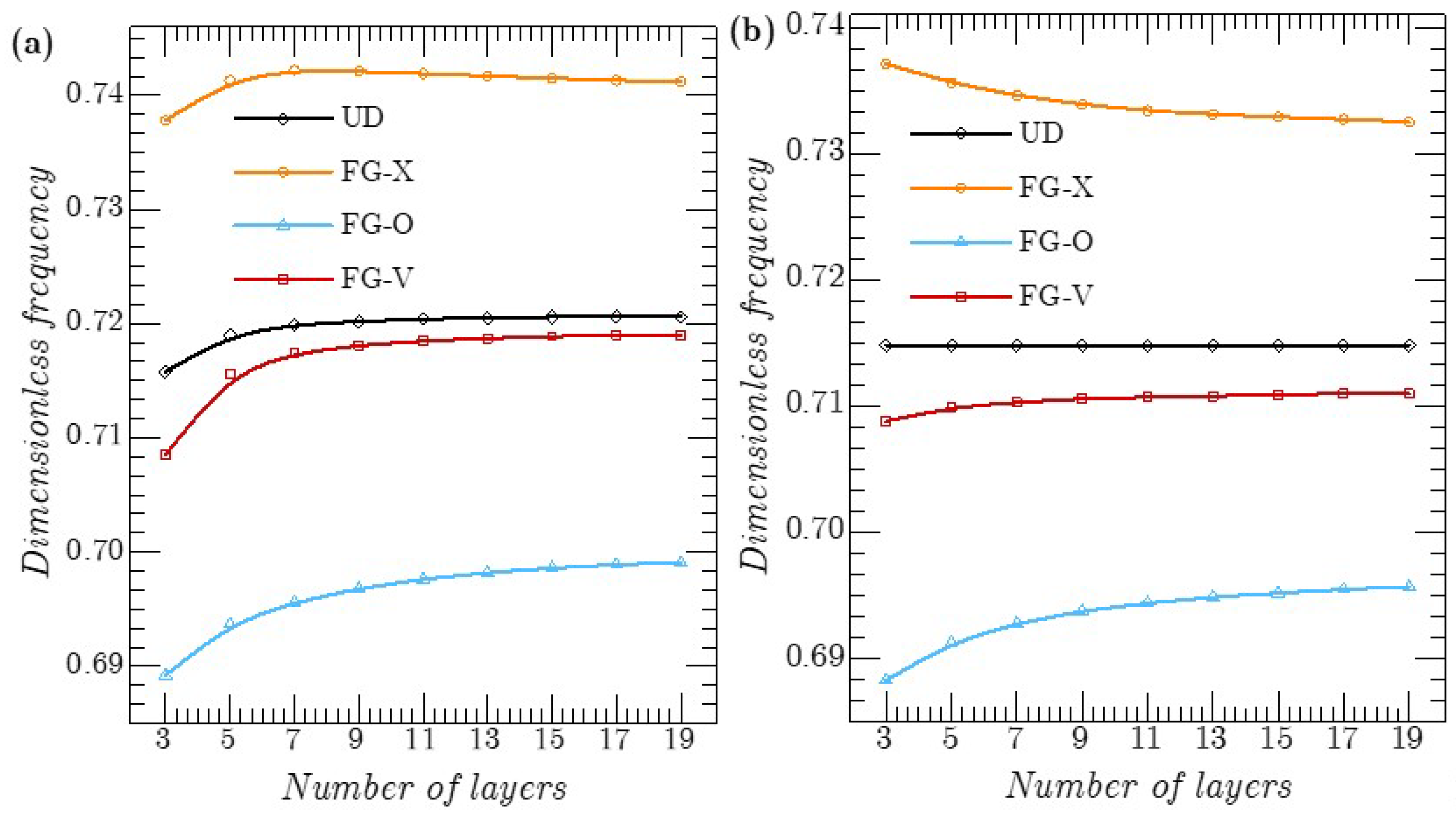
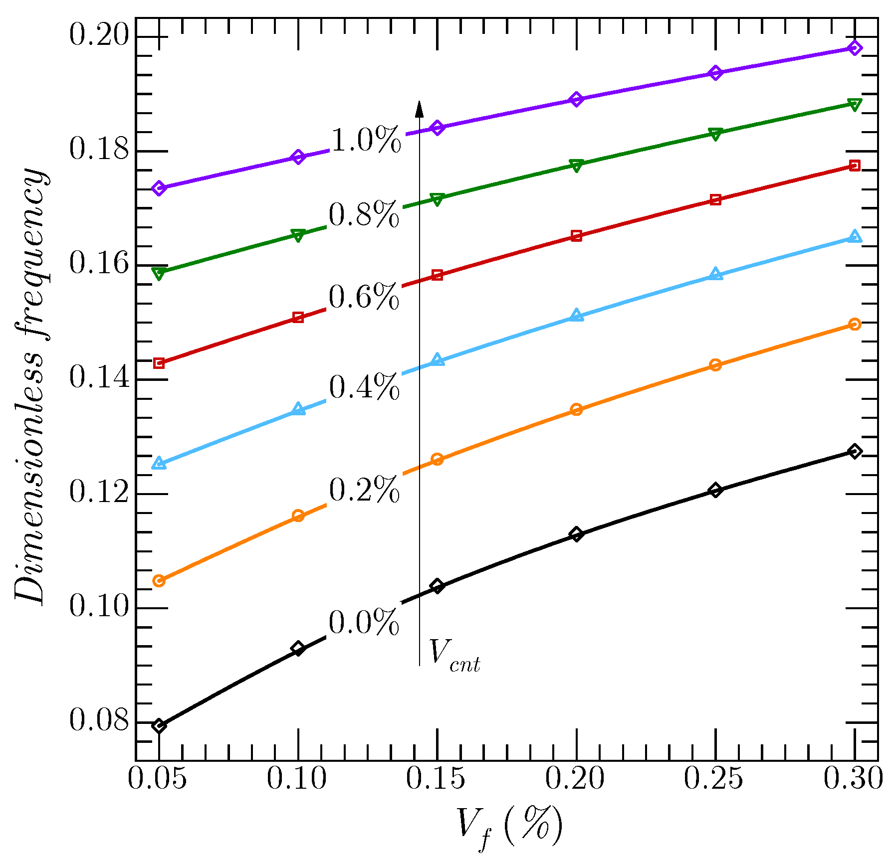
  • It seems that the dimensionless frequencies increased for an increased volume fraction of CNTs/fibers because of a global augmentation in the stiffness of the CNTs/F-RC laminated shell;
  • Because of the considerable reinforcement in the superior and inferior layers, the distribution pattern of FG-X fibers produced the highest values of frequencies;
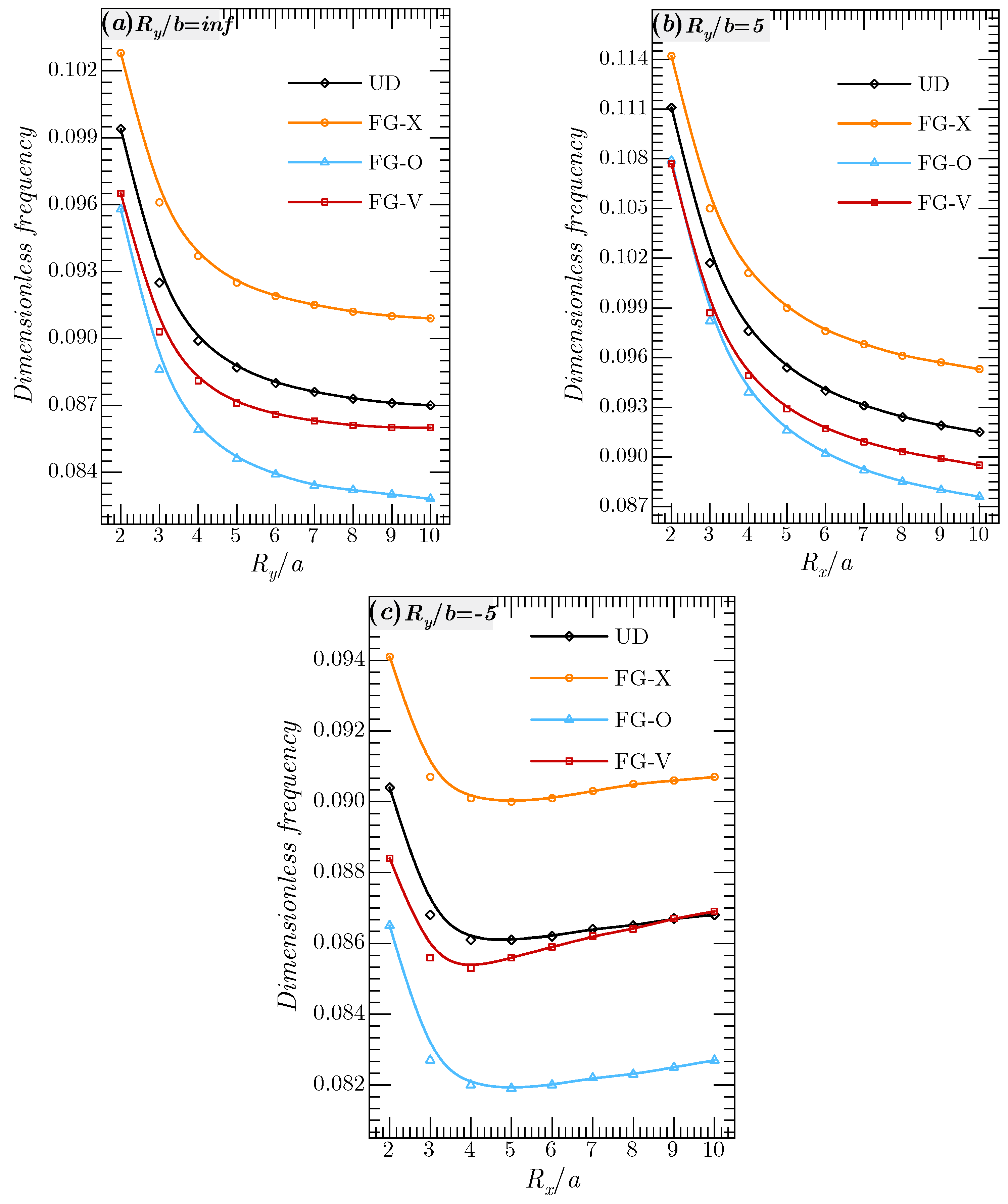
  • The variation of the geometric parameters such as aspect ratio, thickness ratio, and radii of curvature had a significant effect on the vibration response of the proposed structure;
  • The analytical solution proposed in this work could represent valid benchmarks for engineers and researchers for the purposes of the practical design of shell structures.

Author Contributions

A.M. (project administration, funding acquisition, data curation); A.A.D. (software, validation, formal analysis, investigation); M.B. (formal analysis, investigation); A.W. (software, visualization, data curation); R.O. (Conceptualization, methodology, formal analysis); K.H.A. (software, investigation, resources); M.A.H. (methodology, review and editing); A.A. (methodology, software, validation); M.A.E. (Conceptualization, methodology, review and editing). All authors have read and agreed to the published version of the manuscript.

Funding

This research was funded by the Institutional Fund Projects under Grant no. (IFPRC-012-135-2020). Therefore, the authors gratefully acknowledge technical and financial support from the Ministry of Education and King Abdulaziz University, DSR, Jeddah, Saudi Arabia.

Institutional Review Board Statement

Not applicable.

Informed Consent Statement

Not applicable.

Data Availability Statement

Not applicable.

Conflicts of Interest

The authors declare no conflict of interest.

Appendix A

Rigidity matrix elements;
K 11 = A 11 0 a 0 b 3 X m x 3 Y n X m x Y n d x d y + A 66 0 a 0 b X m x 2 Y n y 2 X m x Y n d x d y
K 12 = ( A 12 + A 66 ) 0 a 0 b X m x 2 Y n y 2 X m x Y n d x d y
K 13 = ( A 11 R x + A 12 R y ) 0 a 0 b X m x Y n X m x Y n d x d y B 11 0 a 0 b 3 X m x 3 Y n X m x Y n d x d y ( B 12 + 2 B 66 ) 0 a 0 b X m x 2 Y n y 2 X m x Y n d x d y
K 14 = B 11 s 0 a 0 b 3 X m x 3 Y n X m x Y n d x d y + B 66 s 0 a 0 b X m x 2 Y n y 2 X m x Y n d x d y K 14 = B 11 s 0 a 0 b 3 X m x 3 Y n X m x Y n d x d y + B 66 s 0 a 0 b X m x 2 Y n y 2 X m x Y n d x d y
K 15 = ( B 12 s + B 66 s ) 0 a 0 b X m x 2 Y n y 2 X m x Y n d x d y
K 21 = ( A 12 + A 66 ) 0 a 0 b 2 X m x 1 Y n y X m Y n y d x d y
K 22 = A 22 0 a 0 b X m 3 Y n y 3 X m Y n y d x d y + A 66 0 a 0 b 0 b 2 X m x 2 Y n y X m Y n y d x d y
K 23 = ( A 12 R x + A 22 R y ) 0 a 0 b X m Y n y X m Y n y d x d y B 22 0 a 0 b X m 3 Y n y 3 X m Y n y d x d y ( B 12 + 2 B 66 ) 0 a 0 b 2 X m x 2 Y n y X m Y n y d x d y K 23 = ( A 12 R x + A 22 R y ) 0 a 0 b X m Y n y X m Y n y d x d y B 22 0 a 0 b X m 3 Y n y 3 X m Y n y d x d y ( B 12 + 2 B 66 ) 0 a 0 b 2 X m x 2 Y n y X m Y n y d x d y
K 24 = ( B 12 s + B 66 s ) 0 a 0 b 2 X m x 2 Y n y X m Y n y d x d y
K 25 = B 22 s 0 a 0 b X m 3 Y n y 3 X m Y n y d x d y + B 66 s 0 a 0 b 2 X m x 2 Y n y X m Y n y d x d y
K 31 = ( A 11 R x + A 12 R y ) 0 a 0 b 2 X n x 2 Y n X m Y n d x d y + B 11 0 a 0 b 4 X n x 4 Y n X m Y n d x d y + ( B 12 + 2 B 66 ) 0 a 0 b 2 X m x 2 2 Y n y 2 X m Y n d x d y
K 32 = ( A 12 R x + A 22 R y ) 0 a 0 b X m 2 Y n y 2 X m Y n d x d y + B 22 0 a 0 b X m 4 Y n y 4 X m Y n d x d y + ( B 12 + 2 B 66 ) 0 a 0 b 2 X m x 2 2 Y n y 2 X m Y n d x d y
K 33 = 2 ( B 11 R x + B 12 R y ) 0 a 0 b 2 X n x 2 Y n X m Y n d x d y + 2 ( B 12 R x + B 22 R y ) 0 a 0 b X m 2 Y n y 2 X m Y n d x d y ( A 11 R x 2 + 2 A 12 R x R y + A 22 R y 2 ) 0 a 0 b X m Y n X m Y n d x d y D 11 0 a 0 b 4 X m x 4 Y n X m Y n d x d y D 22 0 a 0 b X m 4 Y n y 4 X m Y n d x d y 2 ( D 12 + 2 D 66 ) 0 a 0 b 2 X m x 2 2 Y n y 2 X m Y n d x d y
K 34 = ( B 11 s R x + B 12 s R y ) 0 a 0 b 2 X n x 2 Y n X m Y n d x d y + D 11 s 0 a 0 b 4 X m x 4 Y n X m Y n d x d y + ( D 12 s + 2 D 66 s ) 0 a 0 b 2 X m x 2 2 Y n y 2 X m Y n d x d y
K 35 = ( B 12 s R x + B 22 s R y ) 0 a 0 b X m 2 Y n y 2 X m Y n d x d y + D 22 s 0 a 0 b X m 4 Y n y 4 X m Y n d x d y + ( D 12 s + 2 D 66 s ) 0 a 0 b 2 X m x 2 2 Y n y 2 X m Y n d x d y
K 41 = B 11 s 0 a 0 b 3 X m x 3 Y n X m x Y n d x d y + B 66 s 0 a 0 b X m x 2 Y n y 2 X m x Y n d x d y
K 42 = ( B 12 s + B 66 s ) 0 a 0 b X m x 2 Y n y 2 X m x Y n d x d y
K 43 = ( B 11 s R x + B 12 s R y ) 0 a 0 b X m x Y n X m x Y n d x d y D 11 s 0 a 0 b 3 X m x 3 Y n X m x Y n d x d y ( D 12 s + 2 D 66 s ) 0 a 0 b X m x 2 Y n y 2 X m x Y n d x d y
K 44 = F 11 s 0 a 0 b 3 X m x 3 Y n X m x Y n d x d y + F 66 s 0 a 0 b X m x 2 Y n y 2 X m x Y n d x d y A 44 s 0 a 0 b X m x Y n X m x Y n d x d y
K 45 = ( F 12 s + F 66 s ) 0 a 0 b X m x 2 Y n y 2 X m x Y n d x d y
K 51 = ( B 12 s + B 66 s ) 0 a 0 b 2 X m x 2 Y n y X m Y n y d x d y
K 52 = B 22 s 0 a 0 b X m 3 Y n y 3 X m Y n y d x d y + B 66 s 0 a 0 b 2 X m x 2 Y n y X m Y n y d x d y
K 53 = ( B 12 s R x + B 22 s R y ) 0 a 0 b X m Y n y X m Y n y d x d y D 22 s 0 a 0 b X m 3 Y n y 3 X m Y n y d x d y ( D 12 s + 2 D 66 s ) 0 a 0 b 2 X m x 2 Y n y X m Y n y d x d y
K 54 = ( F 12 s + F 66 s ) 0 a 0 b 2 X m x 2 Y n y X m Y n y d x d y
K 55 = F 22 s 0 a 0 b X m 3 Y n y 3 X m Y n y d x d y + F 66 s 0 a 0 b 2 X m x 2 Y n y X m Y n y d x d y A 55 s 0 a 0 b X m Y n y X m Y n y d x d y
Mass matrix elements;
M 11 = ( I 0 + 2 I 1 R x + I 3 R y 2 ) 0 a 0 b X m x Y n X m x Y n d x d y
M 13 = ( I 1 + I 2 R x ) 0 a 0 b X m x Y n X m x Y n d x d y
M 14 = ( I 3 + I 4 R x ) 0 a 0 b X m x Y n X m x Y n d x d y
M 22 = ( I 0 + 2 I 1 R y + I 2 R y 2 ) 0 a 0 b X m Y n y X m Y n y d x d y
M 23 = ( I 1 + I 2 R y ) 0 a 0 b X m Y n y X m Y n y d x d y
M 25 = ( I 3 + I 4 R y ) 0 a 0 b X m Y n y X m Y n y d x d y
M 31 = ( I 1 + I 2 R x ) 0 a 0 b 2 X m x 2 Y n X m Y n d x d y
M 32 = ( I 1 + I 2 R y ) I 1 0 a 0 b X m 2 Y n y 2 X m Y n d x d y
M 33 = I 0 0 a 0 b X m Y n X m Y n d x d y I 2 ( 0 a 0 b 2 X m x 2 Y n X m Y n d x d y + 0 a 0 b X m 2 Y n y 2 X m Y n d x d y )
M 34 = I 4 0 a 0 b 2 X m x 2 Y n X m Y n d x d y
M 34 = I 4 0 a 0 b X m 2 Y n y 2 X m Y n d x d y
M 41 = ( I 3 + I 4 R x ) 0 a 0 b X m x Y n X m x Y n d x d y
M 43 = I 4 0 a 0 b X m x Y n X m x Y n d x d y
M 44 = I 5 0 a 0 b X m x Y n X m x Y n d x d y
M 52 = ( I 3 + I 4 R y ) 0 a 0 b X m Y n y X m Y n y d x d y
M 53 = I 4 0 a 0 b X m Y n y X m Y n y d x d y
M 55 = I 5 0 a 0 b X m Y n y X m Y n y d x d y
M 12 = M 15 = M 21 = M 24 = M 42 = M 45 = M 51 = M 54 = 0

References

  1. Daikh, A.A.; Houari MS, A.; Eltaher, M.A. A novel nonlocal strain gradient Quasi-3D bending analysis of sigmoid functionally graded sandwich nanoplates. Compos. Struct. 2021, 262, 113347. [Google Scholar] [CrossRef]
  2. Mohamed, N.; Mohamed, S.A.; Eltaher, M.A. Buckling and post-buckling behaviors of higher order carbon nanotubes using energy-equivalent model. Eng. Comput. 2021, 37, 2823–2836. [Google Scholar] [CrossRef]
  3. Zuo, Y.T.; Liu, H.J. Fractal approach to mechanical and electrical properties of graphene/sic composites. Facta Univ. Ser. Mech. Eng. 2021, 19, 271–284. [Google Scholar] [CrossRef]
  4. He, C.H.; Liu, S.H.; Liu, C.; Mohammad-Sedighi, H. A novel bond stress-slip model for 3-D printed concretes. Discret. Contin. Dyn. Syst.-S 2021, 14, 3459–3478. [Google Scholar] [CrossRef]
  5. Ji, F.Y.; He, C.H.; Zhang, J.J.; He, J.H. A fractal Boussinesq equation for nonlinear transverse vibration of a nanofiber-reinforced concrete pillar. Appl. Math. Model. 2020, 82, 437–448. [Google Scholar] [CrossRef]
  6. Boutahar, Y.; Lebaal, N.; Bassir, D. A Refined Theory for Bending Vibratory Analysis of Thick Functionally Graded Beams. Mathematics 2021, 9, 1422. [Google Scholar] [CrossRef]
  7. Shen, H.S.; Zhang, C.L. Thermal buckling and postbuckling behavior of functionally graded carbon nanotube-reinforced composite plates. Mater. Des. 2010, 31, 3403–3411. [Google Scholar] [CrossRef]
  8. Zhu, P.; Lei, Z.X.; Liew, K.M. Static and free vibration analyses of carbon nanotube-reinforced composite plates using finite element method with first order shear deformation plate theory. Compos. Struct. 2012, 94, 1450–1460. [Google Scholar] [CrossRef]
  9. Alibeigloo, A. Three-dimensional thermoelasticity solution of functionally graded carbon nanotube reinforced composite plate embedded in piezoelectric sensor and actuator layers. Compos. Struct. 2014, 118, 482–495. [Google Scholar] [CrossRef]
  10. Liew, K.M.; Lei, Z.X.; Zhang, L.W. Mechanical analysis of functionally graded carbon nanotube reinforced composites: A review. Compos. Struct. 2015, 120, 90–97. [Google Scholar] [CrossRef]
  11. Zhang, L.W.; Lei, Z.X.; Liew, K.M. Computation of vibration solution for functionally graded carbon nanotube-reinforced composite thick plates resting on elastic foundations using the element-free IMLS-Ritz method. Appl. Math. Comput. 2015, 256, 488–504. [Google Scholar] [CrossRef]
  12. Phung-Van, P.; Thanh, C.L.; Nguyen-Xuan, H.; Abdel-Wahab, M. Nonlinear transient isogeometric analysis of FG-CNTRC nanoplates in thermal environments. Compos. Struct. 2018, 201, 882–892. [Google Scholar] [CrossRef]
  13. Daikh, A.A.; Drai, A.; Houari MS, A.; Eltaher, M.A. Static analysis of multilayer nonlocal strain gradient nanobeam reinforced by carbon nanotubes. Steel Compos. Struct. 2020, 36, 643–656. [Google Scholar] [CrossRef]
  14. He, X.T.; Yang, Z.X.; Li, Y.H.; Li, X.; Sun, J.Y. Application of multi-parameter perturbation method to functionally-graded, thin, circular piezoelectric plates. Mathematics 2020, 8, 342. [Google Scholar] [CrossRef] [Green Version]
  15. Liu, T.; Li, C.; Wang, C.; Lai, J.W.; Cheong, K.H. A simple-FSDT-based isogeometric method for piezoelectric functionally graded plates. Mathematics 2020, 8, 2177. [Google Scholar] [CrossRef]
  16. Li, Y.D.; Tang, Z.C.; Fu, Z.J. Generalized Finite Difference Method for Plate Bending Analysis of Functionally Graded Materials. Mathematics 2020, 8, 1940. [Google Scholar] [CrossRef]
  17. Daikh, A.A.; Houari MS, A.; Belarbi, M.O.; Chakraverty, S.; Eltaher, M.A. Analysis of axially temperature-dependent functionally graded carbon nanotube reinforced composite plates. Eng. Comput. 2021, 2021, 1–22. [Google Scholar] [CrossRef]
  18. Esen, I.; Daikh, A.A.; Eltaher, M.A. Dynamic response of nonlocal strain gradient FG nanobeam reinforced by carbon nanotubes under moving point load. Eur. Phys. J. Plus 2021, 136, 458. [Google Scholar] [CrossRef]
  19. Karamanli, A.; Vo, T.P. Finite element model for carbon nanotube-reinforced and graphene nanoplatelet-reinforced composite beams. Compos. Struct. 2021, 264, 113739. [Google Scholar] [CrossRef]
  20. Karamanli, A.; Aydogdu, M. Vibration behaviors of two-directional carbon nanotube reinforced functionally graded composite plates. Compos. Struct. 2021, 262, 113639. [Google Scholar] [CrossRef]
  21. Daikh, A.A.; Houari MS, A.; Belarbi, M.O.; Mohamed, S.A.; Eltaher, M.A. Static and dynamic stability responses of multilayer functionally graded carbon nanotubes reinforced composite nanoplates via quasi 3D nonlocal strain gradient theory. Def. Technol. 2021, in press. [CrossRef]
  22. Daikh, A.A.; Houari MS, A.; Karami, B.; Eltaher, M.A.; Dimitri, R.; Tornabene, F. Buckling Analysis of CNTRC Curved Sandwich Nanobeams in Thermal Environment. Appl. Sci. 2021, 11, 3250. [Google Scholar] [CrossRef]
  23. Rostami, R.; Mohammadimehr, M. Dynamic stability and bifurcation analysis of sandwich plate with considering FG core and FG-CNTRC face sheets. J. Sandw. Struct. Mater. 2021, 23, 2296–2325. [Google Scholar] [CrossRef]
  24. Khadir, A.I.; Daikh, A.A.; Eltaher, M.A. Novel four-unknowns quasi 3D theory for bending, buckling and free vibration of functionally graded carbon nanotubes reinforced composite laminated nanoplates. Adv. Nano Res. 2021, 11, 621–640. [Google Scholar] [CrossRef]
  25. Babaei, H. On frequency response of FG-CNT reinforced composite pipes in thermally pre/post buckled configurations. Compos. Struct. 2021, 276, 114467. [Google Scholar] [CrossRef]
  26. Duc, N.D.; Minh, P.P. Free vibration analysis of cracked FG CNTRC plates using phase field theory. Aerosp. Sci. Technol. 2021, 112, 106654. [Google Scholar] [CrossRef]
  27. Adhikari, B.; Singh, B.N. A Coupled Mori–Tanaka model and FEM RVE approach for the geometrical nonlinear dynamic response of the FG-CNTRC plate based on a novel shear strain function using isogeometric finite element procedure. Compos. Struct. 2022, 280, 114947. [Google Scholar] [CrossRef]
  28. Shen, H.S. Postbuckling of nanotube-reinforced composite cylindrical shells in thermal environments, Part I: Axially-loaded shells. Compos. Struct. 2011, 93, 2096–2108. [Google Scholar] [CrossRef]
  29. Shen, H.S. Postbuckling of nanotube-reinforced composite cylindrical shells in thermal environments, Part II: Pressure-loaded shells. Compos. Struct. 2011, 93, 2496–2503. [Google Scholar] [CrossRef]
  30. Aragh, B.S.; Barati, A.N.; Hedayati, H. Eshelby–Mori–Tanaka approach for vibrational behavior of continuously graded carbon nanotube-reinforced cylindrical panels. Compos. Part B Eng. 2012, 43, 1943–1954. [Google Scholar] [CrossRef]
  31. Shen, H.S. Torsional postbuckling of nanotube-reinforced composite cylindrical shells in thermal environments. Compos. Struct. 2014, 116, 477–488. [Google Scholar] [CrossRef]
  32. Mirzaei, M.; Kiani, Y. Snap-through phenomenon in a thermally postbuckled temperature dependent sandwich beam with FG-CNTRC face sheets. Compos. Struct. 2015, 134, 1004–1013. [Google Scholar] [CrossRef]
  33. Thomas, B.; Roy, T. Vibration analysis of functionally graded carbon nanotube-reinforced composite shell structures. Acta Mech. 2016, 227, 581–599. [Google Scholar] [CrossRef]
  34. Pouresmaeeli, S.; Fazelzadeh, S. Frequency analysis of doubly curved functionally graded carbon nanotube-reinforced composite panels. Acta Mech. 2016, 227, 2765–2794. [Google Scholar] [CrossRef]
  35. Shojaee, M.; Setoodeh, A.R.; Malekzadeh, P. Vibration of functionally graded CNTs-reinforced skewed cylindrical panels using a transformed differential quadrature method. Acta Mech. 2017, 228, 2691–2711. [Google Scholar] [CrossRef]
  36. Tohidi, H.; Hosseini-Hashemi, S.H.; Maghsoudpour, A. Nonlinear size-dependent dynamic buckling analysis of embedded micro cylindrical shells reinforced with agglomerated CNTs using strain gradient theory. Microsyst. Technol. 2017, 23, 5727–5744. [Google Scholar] [CrossRef]
  37. Avramov, K.V.; Chernobryvko, M.; Uspensky, B.; Seitkazenova, K.K.; Myrzaliyev, D. Self-sustained vibrations of functionally graded carbon nanotubes-reinforced composite cylindrical shells in supersonic flow. Nonlinear Dyn. 2019, 98, 1853–1876. [Google Scholar] [CrossRef]
  38. Aminipour, H.; Janghorban, M.; Civalek, O. Analysis of functionally graded doubly-curved shells with different materials via higher order shear deformation theory. Compos. Struct. 2020, 251, 112645. [Google Scholar] [CrossRef]
  39. Ahmadi, H.; Bayat, A.; Duc, N.D. Nonlinear forced vibrations analysis of imperfect stiffened FG doubly curved shallow shell in thermal environment using multiple scales method. Compos. Struct. 2021, 256, 113090. [Google Scholar] [CrossRef]
  40. Babaei, H.; Kiani, Y.; Eslami, M.R. Vibrational behavior of thermally pre-/post-buckled FG-CNTRC beams on a nonlinear elastic foundation: A two-step perturbation technique. Acta Mech. 2021, 232, 3897–3915. [Google Scholar] [CrossRef]
  41. Chakraborty, S.; Dey, T. Non-linear stability analysis of CNT reinforced composite cylindrical shell panel subjected to thermomechanical loading. Compos. Struct. 2021, 255, 112995. [Google Scholar] [CrossRef]
  42. Chakraborty, S.; Dey, T.; Kumar, R. Instability characteristics of damped CNT reinforced laminated shell panels subjected to in-plane excitations and thermal loading. Structures 2021, 34, 2936–2949. [Google Scholar] [CrossRef]
  43. Dai, Z.; Zhang, L.; Bolandi, S.Y.; Habibi, M. On the vibrations of the non-polynomial viscoelastic composite open-type shell under residual stresses. Compos. Struct. 2021, 263, 113599. [Google Scholar] [CrossRef]
  44. Fares, M.E.; Elmarghany, M.K.; Atta, D.; Salem, M.G. An improved layerwise formulation for free vibrations of multilayered FG truncated conical shells reinforced by carbon nanotubes. Compos. Struct. 2021, 275, 114372. [Google Scholar] [CrossRef]
  45. Fu, T.; Wu, X.; Xiao, Z.; Chen, Z. Dynamic instability analysis of FG-CNTRC laminated conical shells surrounded by elastic foundations within FSDT. Eur. J. Mech.-A/Solids 2021, 85, 104139. [Google Scholar] [CrossRef]
  46. Yadav, A.; Amabili, M.; Panda, S.K.; Dey, T.; Kumar, R. Nonlinear damped vibrations of three-phase CNT-FRC circular cylindrical shell. Compos. Struct. 2021, 255, 112939. [Google Scholar] [CrossRef]
  47. Mohammadi, H.; Setoodeh, A.R.; Vassilopoulos, A.P. Isogeometric Kirchhoff–Love shell patches in free and forced vibration of sinusoidally corrugated FG carbon nanotube-reinforced composite panels. Thin-Walled Struct. 2022, 171, 108707. [Google Scholar] [CrossRef]
  48. Cong, P.H.; Trung, V.D.; Khoa, N.D.; Duc, N.D. Vibration and nonlinear dynamic response of temperature-dependent FG-CNTRC laminated double curved shallow shell with positive and negative Poisson’s ratio. Thin-Walled Struct. 2022, 171, 108713. [Google Scholar] [CrossRef]
  49. Babaei, H. Free vibration and snap-through instability of FG-CNTRC shallow arches supported on nonlinear elastic foundation. Appl. Math. Comput. 2022, 413, 126606. [Google Scholar] [CrossRef]
  50. Yengejeh, S.I.; Kazemi, S.A.; Öchsner, A. Carbon nanotubes as reinforcement in composites: A review of the analytical, numerical and experimental approaches. Comput. Mater. Sci. 2017, 136, 85–101. [Google Scholar] [CrossRef]
  51. Shahmohammadi, M.A.; Azhari, M.; Saadatpour, M.M.; Salehipour, H.; Civalek, Ö. Dynamic instability analysis of general shells reinforced with polymeric matrix and carbon fibers using a coupled IG-SFSM formulation. Compos. Struct. 2021, 263, 113720. [Google Scholar] [CrossRef]
  52. Mehrabadi, S.J.; Aragh, B.S.; Khoshkhahesh, V.; Taherpour, A. Mechanical buckling of nanocomposite rectangular plate reinforced by aligned and straight single-walled carbon nanotubes. Compos. Part B Eng. 2012, 43, 2031–2040. [Google Scholar] [CrossRef]
  53. Alijani, F.; Amabili, M.; Karagiozis, K.; Bakhtiari-Nejad, F. Nonlinear vibrations of functionally graded doubly curved shallow shells. J. Sound Vib. 2011, 330, 1432–1454. [Google Scholar] [CrossRef]
  54. Matsunaga, H. Free vibration and stability of functionally graded shallow shells according to a 2D higher-order deformation theory. Compos. Struct. 2008, 84, 132–146. [Google Scholar] [CrossRef]
  55. Chorfi, S.M.; Houmat, A. Non-linear free vibration of a functionally graded doubly-curved shallow shell of elliptical plan-form. Compos. Struct. 2010, 92, 2573–2581. [Google Scholar] [CrossRef]
  56. Trinh, M.C.; Kim, S.E. A three variable refined shear deformation theory for porous functionally graded doubly curved shell analysis. Aerosp. Sci. Technol. 2019, 94, 105356. [Google Scholar] [CrossRef]
  57. Tornabene, F.; Fantuzzi, N.; Bacciocchi, M. Linear static response of nanocomposite plates and shells reinforced by agglomerated carbon nanotubes. Compos. Part B Eng. 2017, 115, 449–476. [Google Scholar] [CrossRef]
  58. Bowles, D.E.; Tompkins, S.S. Prediction of coefficients of thermal expansion for unidirectional composites. J. Compos. Mater. 1989, 23, 370–388. [Google Scholar] [CrossRef]
Figure 1. The material properties, geometry, and coordinate system of the shell, (a) Geometry and coordinates, (b) Gradation types of material.
Mathematics 10 00408 g001
Figure 2. Forms of various plate/shells.
Mathematics 10 00408 g002
Figure 3. The volume-fractions of the fibers along the thickness of the shell ( V m a x f = 0.3 , V m i n f = 0.1 ).
Mathematics 10 00408 g003
Figure 4. The effect of the number of layers “N”: (a) Cross-ply fibers (b) Unidirectional fibers (Plate, SSSS, b / a = 1 , a / h = 10 , V c n t = 0.01 , V m a x f = 0.3 , V m i n f = 0.1 ).
Mathematics 10 00408 g004
Figure 5. The effect of the radius of curvature R/a on the dimensionless frequency of various shell types (Cross-ply, SSSS, N = 9 , b / a = 1 , a / h = 10 , V c n t = 0.01 , V m a x f = 0.3 , V m i n f = 0.1 ).
Mathematics 10 00408 g005
Figure 6. The effect of the volume fraction of fibers and CNTs (Plate, Cross-ply, SSSS, N = 9 , b / a = 1 , a / h = 10 , V m i n f = 0.05 ).
Mathematics 10 00408 g006
Figure 7. The effect of the geometry parameters b/a and a/h on the dimensionless frequency of a spherical shell for various boundary conditions ( N = 9 , V c n t = 0.01 , V m a x f = 0.1 , V m i n f = 0.3 ). (a) inplane ratio b/a, (b) slenderness ratio a/h.
Mathematics 10 00408 g007
Figure 8. The effect of the modes of vibration “m” and “n” on the dimensionless frequency of a spherical shell ( R x = R y = 5   , SSSS, N = 9 , b / a = 1 , a / h = 10 , V c n t = 0.01 , V m a x f = 0.3 , V m i n f = 0.1 ).
Mathematics 10 00408 g008
Table 1. Hill’s elastic moduli for (10, 10) single-walled carbon nanotubes [52].
k c n t   [ G P a ] l c n t   [ G P a ] m c n t   [ G P a ] n c n t   [ G P a ] p c n t   [ G P a ]
27188171089442
Table 2. The essential boundary conditions.
BCs.Boundaries Parallel to the x-AxisBoundaries Parallel to the y-Axis
Simply supported (S) u 0 = w 0 = ψ x = M y y = N y y = 0 v 0 = w 0 = ψ y = M x x = N x x = 0
Clamped (C) u 0 = v 0 = w 0 = ψ x = ψ y = 0 u 0 = v 0 = w 0 = ψ x = ψ y = 0
Table 3. The admissible functions X m ( x ) and Y n ( y ) .
BCs. The   Functions   X m   and   Y n
X m ( x ) Y n ( y )
SSSS sin ( α x ) sin ( β y )
CCCC sin 2 ( α x ) sin 2 ( β y )
CSCS sin ( α x ) [ cos ( α x ) 1 ] sin ( β y ) [ cos ( β y ) 1 ]
CCSS sin 2 ( α x ) sin ( β y )
CSSS sin ( α x ) [ cos ( α x ) 1 ] sin ( β y )
CCCS sin 2 ( α x ) sin ( β y ) [ cos ( β y ) 1 ]
Where α = m π / a , β = n π / b . m and n are mode numbers.
Table 4. Comparison of the natural frequency parameter ( ω ˜ = ω h ρ c / E c ) for simply supported Al/Al2O3 functionally graded square plates and doubly curved shells (a = b = 10h, m = n = 1).
a / R x b / R y p Alijani
[53]
Matsunaga
[54]
Chorfi
[55]
Trinh
[56]
Present
Plate0000.05970.05880.05770.05770.0577
0.50.05060.04920.04900.04900.0490
10.04560.04300.04420.04420.0442
40.03960.03810.03830.03810.0380
100.03800.03640.03660.03640.0363
Spherical0.50.500.07790.07510.07620.07610.0753
0.50.06760.06570.06640.06620.0653
10.06170.06010.06070.06050.0595
40.05190.05030.05090.05060.0496
100.04820.04640.04710.04670.0459
Cylindrical0.5000.06480.06220.06290.06280.0622
0.50.05530.05350.05400.05380.0533
10.05010.04850.04900.04880.0482
40.04300.04130.04190.04160.0410
100.04080.03900.03950.03920.0387
Hyperbolic–paraboloidal0.5−0.500.05970.05630.05800.05770.0563
0.50.05060.04790.04930.04900.0478
10.04560.04320.04450.04420.0431
40.03960.03720.03850.03810.0371
100.03800.03550.03680.03640.0354
Table 5. The effect of the number of layers and fiber distribution patterns on the dimensionless frequency of cross-ply CNTs/F-RC shells for various curvature radii (SSSS, b / a = 1 , a / h = 10 , V c n t = 0.01 , V m a x f = 0.3 , V m i n f = 0.1 ).
R x / a R y / b NUDFG-XFG-OFG-V
Plateinfinf30.18960.18620.17500.1779
70.19000.18400.17340.1783
110.19000.19270.18230.1881
150.19010.20400.19340.1984
190.19010.19760.18210.1893
Cylindrical shell5inf30.19170.18830.17780.1789
70.19210.18620.17620.1792
110.19220.19480.18480.1888
150.19220.20590.19590.1988
190.19220.19970.18440.1899
Spherical shell5530.19860.19530.18560.1855
70.19910.19330.18420.1854
110.19920.20160.19240.1947
150.19920.21250.20310.2041
190.19920.20640.19170.1955
Elliptical–paraboloid shell57.530.19590.19250.18250.1828
70.19640.19050.18110.1829
110.19640.19890.18940.1923
150.19640.20980.20030.2019
190.19640.20380.18880.1932
Hyperbolic–paraboloidal shell5−530.18880.18550.17440.1769
70.18920.18340.17280.1776
110.18930.19200.18160.1873
150.18930.20320.19270.1975
190.18930.19690.18140.1885
Table 6. The effect of the number of layers and fiber distribution patterns on the dimensionless frequency of unidirectional F/CNT-RC shells for various curvature radii (SSSS, b / a = 1 , a / h = 10 , V c n t = 0.01 , V m a x f = 0.3 , V m i n f = 0.1 ).
R x / a R y / b NUDFG-XFG-OFG-V
Plateinfinf30.18940.18580.17480.1776
70.18940.18340.17350.1773
110.18940.19190.18180.1868
150.18940.20290.19280.1968
190.18940.19670.18170.1879
Cylindrical shell5inf30.19130.18770.17710.1790
70.19130.18540.17540.1787
110.19130.19370.18400.1881
150.19130.20460.19480.1979
190.19130.19850.18380.1891
Spherical shell5530.19790.19410.18410.1855
70.19790.19160.18220.1849
110.19790.19950.19010.1939
150.19790.21020.20070.2035
190.19790.20480.19060.1955
Elliptical–paraboloid shell57.530.19530.19150.18130.1829
70.19530.18910.17950.1824
110.19530.19720.18770.1916
150.19530.20790.19830.2012
190.19530.20230.18790.1929
Hyperbolic–paraboloidal shell5−530.18870.18520.17430.1768
70.18870.18310.17280.1768
110.18870.19170.18170.1864
150.18870.20260.19260.1960
190.18870.19590.18100.1867
Table 7. The effect of the volume fraction of CNTs and fiber distribution patterns on the dimensionless frequency of cross-ply F/CNT-RC shells (SSSS, b / a = 1 , N = 9 , a / h = 10 , V m a x f = 0.3 , V m i n f = 0.1 ).
Type of Shells Fiber Distribution Pattern
V c n t FRC UDFRC FG-XFRC FG-OFRC FG-V
Plate0.0%0.11760.12880.10330.1140
0.2%0.13870.15080.12460.1358
0.4%0.15430.16580.14140.1521
0.6%0.16760.17810.15600.1659
0.8%0.17940.18880.16910.1780
1.0%0.19000.19840.18110.1891
Cylindrical shell0.0%0.11810.12920.10390.1140
0.2%0.13980.15170.12580.1358
0.4%0.15570.16710.14300.1522
0.6%0.16930.17970.15780.1661
0.8%0.18130.19060.17120.1785
1.0%0.19220.20040.18340.1896
Spherical shell0.0%0.12000.13100.10620.1163
0.2%0.14340.15510.12980.1389
0.4%0.16050.17150.14810.1561
0.6%0.17490.18500.16390.1707
0.8%0.18770.19670.17790.1836
1.0%0.19920.20710.19070.1953
Elliptical–paraboloid shell0.0%0.11930.13030.10530.1154
0.2%0.14190.15380.12830.1377
0.4%0.15860.16980.14610.1545
0.6%0.17270.18290.16150.1688
0.8%0.18520.19430.17530.1815
1.0%0.19640.20450.18780.1929
Hyperbolic–paraboloidal shell0.0%0.11710.12830.10290.1125
0.2%0.13820.15020.12410.1348
0.4%0.15370.16510.14080.1511
0.6%0.16690.17740.15540.1649
0.8%0.17860.18880.16840.1771
1.0%0.18930.19760.18040.1881
Table 8. The effect of the volume fraction and distribution patterns of the fibers on the dimensionless frequency of cross-ply F/CNT-RC shells (SSSS, b / a = 1 , a / h = 10 , N = 9 , V c n t = 0.01 , V m i n f = 0.05 ).
Type of Shells Fiber Distribution Pattern
V F FRC UDFRC FG-XFRC FG-OFRC FG-V
Plate5%0.17350.17350.17350.1735
10%0.17650.17900.17400.1765
20%0.18220.18910.17510.18158
30%0.18750.19820.17600.1859
Cylindrical shell5%0.17580.17580.17580.1758
10%0.17880.18120.17630.1782
20%0.18440.19120.17740.1823
30%0.18970.20020.17840.1860
Spherical shell5%0.18310.18310.18310.1831
10%0.18610.18840.18370.1850
20%0.19160.19820.18480.1883
30%0.19680.20690.18590.1912
Elliptical–paraboloid shell5%0.18020.18020.18020.1802
10%0.18320.18560.18080.1822
20%0.18880.19540.18190.1858
30%0.19400.20420.18290.1890
Hyperbolic–paraboloidal shell0.0%0.17280.17280.17280.1728
0.2%0.17580.17830.17330.1757
0.8%0.18150.18840.17430.1808
1.0%0.18680.19740.17530.1850
Table 9. The effect of different boundary conditions and fiber distribution patterns on the dimensionless frequency of cross-ply F/CNT-RC shells ( b / a = 1 , N = 9 , a / h = 10 , V c n t = 0.01 , V m a x f = 0.3 , V m i n f = 0.1 ).
Type of ShellsBCs.Fiber Distribution Pattern
FRC UDFRC FG-XFRC FG-OFRC FG-V
PlateSSSS0.19000.19840.18110.1891
CCCC0.35990.37780.33980.3572
CCSS0.29780.31620.27670.2950
CSCS0.34090.35670.32370.3389
CSSS0.28210.29890.26340.2797
CCCS0.23860.25810.21550.2353
Cylindrical shellSSSS0.19220.20040.18340.1896
CCCC0.36610.38390.34610.3633
CCSS0.30530.32350.28440.3023
CSCS0.34490.36070.32770.3421
CSSS0.28660.30330.26810.2837
CCCS0.24840.26760.22580.2452
Spherical shellSSSS0.19920.20710.19070.1953
CCCC0.37290.39040.35330.3706
CCSS0.30830.32640.28770.3042
CSCS0.35010.36560.33320.3470
CSSS0.29110.30750.27290.2868
CCCS0.26110.27940.23980.2584
Elliptical–paraboloid shellSSSS0.19640.20450.18780.1929
CCCC0.36940.38710.34960.3669
CCSS0.30690.32510.28620.3032
CSCS0.34760.36320.33050.3446
CSSS0.28920.30570.27080.2853
CCCS0.25460.27340.23270.2517
Hyperbolic–paraboloidal shellSSSS0.18930.19760.18040.1881
CCCC0.37030.38790.35060.3671
CCSS0.30560.32380.28480.3038
CSCS0.34690.36250.32980.3443
CSSS0.28650.30310.26800.2851
CCCS0.25660.27520.23490.2532
Table 10. The effect of geometric parameters a/h and b/a on the dimensionless frequency of cross-ply F/CNT-RC shells for various curvature radii (SSSS, N = 9 , V c n t = 0.01 , V m a x f = 0.3 , V m i n f = 0.1 ).
Type of Shells b / a a/h
5102030
Plate0.51.46890.45590.12310.0556
10.70770.19840.05130.0230
20.52300.14370.03690.0165
30.49520.13580.03480.0156
Cylindrical shell0.51.47150.45870.12600.0584
10.70920.20040.05350.0251
20.52260.14400.03740.0170
30.49440.13560.03500.0157
Spherical shell0.51.47490.46200.12940.0617
10.71640.20710.05970.0307
20.52760.14860.04170.0210
30.49730.13830.03750.0181
Elliptical–paraboloid shell0.51.47410.46090.12820.0605
10.71370.20450.05720.0286
20.52550.14660.03990.0193
30.49600.13710.03630.0170
Hyperbolic–paraboloidal shell0.51.46520.45520.12350.0562
10.70490.19760.05110.0229
20.52190.14380.03740.0170
30.49470.13610.03540.0162
Publisher’s Note: MDPI stays neutral with regard to jurisdictional claims in published maps and institutional affiliations.

