Abstract
Deposits of natural gas hydrates are some of the most promising sources of hydrocarbons. According to studies, at the current level of natural gas consumption, the traditional reserves will last for about 50 years, and the gas hydrate deposits will last for at least 250 years. Therefore, interest in the study of gas hydrates is associated first of all with gas production from gas hydrate deposits. Additionally, gas hydrates are widely studied for solving practical problems, such as transportation and storage of natural gas, utilization of industrial gases and environmental and technological disasters associated with gas hydrates. When solving practical problems related to gas hydrates, in addition to laboratory and field studies, mathematical modeling is also widely used. This article presents the mathematical models of non-isothermal flow in a porous medium considering the decomposition of gas hydrate. The general forms of the mass conservation equations, Darcy’s law and the energy conservation equation are given. The article also presents derivations of the equations for taking into account the latent heat of phase transitions and non-isothermal filtration parameters for the energy conservation equation. This may be useful for researchers to better understand the construction of the model. For the parameters included in the basic equations, various dependencies are used in different works. In all the articles found, most often there was an emphasis on one or two of the parameters. The main feature of this article is summarizing various dependencies for a large number of parameters. Additionally, graphs of these dependencies are presented so that the reader can independently evaluate the differences between them. The most preferred dependencies for calculations are noted and explained.
MSC:
76-10; 35Q79
1. Introduction
Gas hydrates are crystalline, solid substances consisting of water molecules linked by hydrogen bonds, thereby forming cavities, and molecules of other substances contained in these cavities [1,2]. In nature, such substances are most often methane, ethane, propane and carbon dioxide. The formation of mixed hydrates containing various substances in the cavities is also possible. The crystalline structure and filling of the gas hydrates’ cavities depend on the guest molecule and the conditions of the hydrate formation. The composition of gas hydrates is usually determined by the expression M·nH2O, where n is the number of water molecules per one guest molecule. One cubic meter of methane hydrate contains about 160 m3 of gas reduced to standard conditions (273.15 K and 101,325 Pa) and about 0.8 m3 of water. Figure 1 shows a cavity containing a methane molecule and the physical appearance of gas hydrates [3].
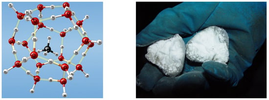
Figure 1.
Methane molecule in a cavity of water molecules and the physical appearance of gas hydrates.
Gas hydrates form at particular pressures and temperatures. Figure 2 shows phase equilibrium curves for the “H2O–CH4” system [4].
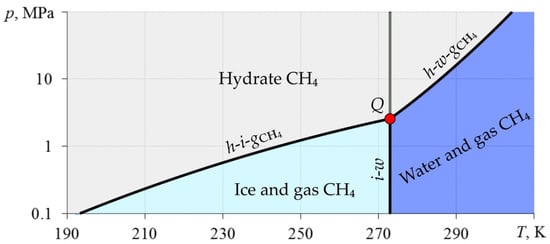
Figure 2.
Phase diagram of the “H2O–CH4” system. i-w—phase equilibrium “ice–water”; h-i-gCH4—phase equilibrium “methane hydrate–ice–methane”; h-w-gCH4—phase equilibrium “methane-hydrate–water–methane”; Q is the quadruple point at which all four phases coexist.
In some cases, the effect of self-preservation of gas hydrates is possible [1,5]: if at T < 0 °C a gas hydrate begins to decompose, then an ice film forms on its surface. After this, the film reaches a certain critical thickness, and further decomposition almost completely stops.
The existing deposits of gas hydrates are one of the most promising sources of hydrocarbons [6,7,8,9]. According to BP’s Statistical Review of World Energy 2020, at the end of 2019, the amount of the world’s conventionally recoverable natural gas reserves is 198.8 trillion m3 [10]. According to “Resources to Reserves 2013”, the amount of gas in gas hydrates is estimated to be from 1000 to 20,000 trillion m3 [11]. Consequently, at the current level of natural gas consumption of 4.04 trillion m3 [12], conventional reserves will last for about 50 years, and gas from hydrates will last for at least 250 years. According to studies, about 20% of the land in the permafrost zone and up to 90% of the bottom of the seas and oceans are in the gas hydrate stability zone (this is the zone in which the thermodynamic conditions are above the h-i-gCH4 and h-w-gCH4 curves, Figure 2) [1,13,14,15,16]. So far, deposits of gas hydrates have been discovered along the coasts of Eurasia, North and South America, Australia and Japan; and at the depths of the Black, Caspian and Mediterranean seas, Lake Baikal, etc. [17,18]. The first industrial production of gas from gas hydrates was carried out in 1969 in Russia at the Messoyakha gas field, where the extraction of free natural gas led to the release of gas from gas hydrates [19]. In 2002, during the JAPEX/GCS/JNOC Mallik 5L-38 research program in Canada, a small-scale field test was carried out to extract gas from hydrates with a pressure reduction method [20,21,22,23]. After that, in 2007–2008, a full-scale production test was carried out using the Aurora/JOGMEC/NRCan Mallik 2L-38 program [24,25,26,27]. At the beginning of 2013, gas was produced from a hydrate formation at a depth of 300 m below the seabed near the island of Honshu in Japan, where about 119 thousand m3 of methane was produced in 6 days; production was consequently halted due to equipment becoming clogged with sand [28]. To develop existing gas hydrate deposits, a number of researchers proposed to use the following methods: depression (pressure reduction); the thermal method (temperature increase); the introduction of inhibitors; and the replacement of methane in the composition of the hydrate with carbon dioxide [29]. The most promising method of gas production from gas hydrate deposits is considered to be lowering the bottomhole pressure below the equilibrium pressure of hydrate formation for a given reservoir temperature (i.e., below the h-i-gCH4 and h-w-gCH4 curves, Figure 2) to initiate the process of gas hydrate decomposition [30]. After that, the released free gas can be recovered by conventional gas-production methods. Additionally, replacement of CH4-CO2 in the composition of gas hydrate has been considered a promising method for extracting methane from gas hydrate deposits in the last two decades [31,32,33,34,35,36,37,38,39,40]. This is possible due to the fact that carbon dioxide hydrate is thermodynamically more stable with the same parameters (pressure and temperature) than methane hydrate. Carbon dioxide replaces the methane in the hydrate, after which the released methane is extracted. This method allows one, in addition to extracting energy carriers, to solve the problem of carbon dioxide utilization. In addition to the main methods mentioned above, the decomposition of gas hydrate can occur with exposure to high-frequency electromagnetic radiation [41].
The study of gas hydrates is also necessary to prevent possible environmental and technological disasters. For example, in the development of fields in the northern regions, sudden gas outbursts can occur due to the decomposition of gas hydrates during drilling and well operations [1,42,43]. According to some researchers, climate warming in the Arctic latitudes can lead to a rapid release of gas from the decomposition of natural gas hydrates, which might explain the presence of funnel craters found in the Yamal and Krasnoyarsk regions of Russia [16]. On the shelf of the Arctic seas, the presence of so-called gas flares (fountains of gas bubbles) was observed, which reached a diameter of 1 km; and the probable cause of this phenomenon is the decomposition of underwater gas hydrates [44]. When methane is released from gas hydrates into the atmosphere, an increase in the greenhouse effect is possible, which can lead to an acceleration of the warming process and the decomposition of natural gas hydrate deposits.
It is possible to use gas hydrates in the transportation and storage of various gases, their purification and separation. At the end of the last century, it was discovered that even at atmospheric pressure, hydrates can be relatively stable due to the self-preservation effect described above. This is a huge advantage to storing and transporting gases in the form of gas hydrates [45]. In Japan, in 2003, Mitsui Engineering and Shipbuilding (MES) for the first time developed a project for the transportation and storage of natural gas in the form of hydrate granules, and in 2009, along with Chugoku Electric Power, built the first plant for the production of natural gas hydrate with a capacity of 5 tons/day [46]. A concept for the production of gas hydrates in the northern regions of Russia using natural conditions has been developed. Experimental results have been obtained about the creation of methane and ethane hydrates under free-convection conditions in closed-type reactor chambers [47]. One of the urgent environmental problems is considered in [48,49], where the utilization of sulfur dioxide produced by metallurgical companies is studied. The storage of sulfur dioxide in underground facilities is associated with the risks of its possible leakage, and the injection of this gas into natural reservoirs would allow its storage in a stable gas hydrate form. This circumstance provides reliable storage of sulfur dioxide for a relatively low price [50].
In the gas transportation industry, gas hydrates are considered to have a negative effect, since the formation of a solid phase in wells and pipelines leads to deterioration in their hydraulic capacity and even complete blockage of the pipes [2,51,52,53]. Therefore, it is necessary to prevent the formation of gas hydrates in equipment used in the oil and gas industry. The following methods may be used: gas purification from water vapor, the use of inhibitors, and gas heating. The most common of these methods is the injection of organic inhibitors (methanol, ethanol, etc.). Their presence reduces the activity of water and shifts the conditions of gas hydrate phase equilibrium to lower temperatures and high pressures [54].
To solve the problems of natural gas production, and the transportation and storage of gases in the form of gas hydrates, and to study environmental, geological and technological problems associated with gas hydrates, it is necessary to build mathematical models that take into account the main features of the studied processes. Multivariate calculations using such mathematical models make it possible to make fairly accurate forecasts of the process development and reduce the amounts of experimental and field data required. This contributes to the implementation of effective technological and engineering solutions to problems associated with gas hydrates.
This paper presents the general equations of a mathematical model of non-isothermal filtration of gas and water in a porous medium considering the decomposition of gas hydrate. To construct this model, widely known equations of continuum mechanics are used, which the existing well-tested hydrodynamic simulators are based on. The works of various researchers were reviewed to determine the individual parameters included in this model. Methods for calculating these parameters are described, and the most preferred of them are indicated. Such models allow one to study some general fundamental regularities of gas production from gas hydrate deposits.
2. Mathematical Modeling
The basic equations of mathematical models of non-isothermal flow in a porous medium considering the formation or decomposition of gas hydrates are presented in this section. Different sources use different symbols for different parameters. Hence, for the convenience of general perception, unified designations will be used, which may differ from those of the original sources.
The general form of the equations for conservation of masses of gas, water, hydrate and porous skeleton can be written as [55]:
Here and below, the subscripts j, k = g, w and h refer to gas, water and hydrate, respectively; the subscript sk refers to the porous-medium skeleton; t is time, s; φ is porosity; Sj is the saturation of pores with the j-th phase; ρj is the density of the j-th phase, kg/m3; is the speed of the j-th phase, m/s; Jkj is the intensity of mass transition from the k-th phase to the j-th phase in a unit of volume per unit of time, kg/(m3·s). The term on the equation’s left side is the change in the j-th phase mass, the first term on the right side is the mass transfer of the j-th phase, and the second term on the right side is phase transitions. The hydrate is considered immobile (), and for it, the first term on the right side is equal to zero. The porous-medium skeleton is assumed to be immobile; its mass is constant.
Darcy’s law is used to describe the motion of phases in a porous medium:
Here, is the filtration velocity vector of the j-th phase, m/s; k is the permeability tensor of the porous medium—the use of the tensor allows us to consider the permeability at each point in different directions, m2; krj is the relative permeability of the j-th phase; µj is the dynamic viscosity of the j-th phase, Pa·s; pj is the pressure of the j-th phase, Pa; is the acceleration of gravity vector considering that vertical axis is directed upwards, m/s2.
The first law of thermodynamics is used as the basic equation of the energy conservation [56]:
Here, U is the internal energy of some volume of saturated porous medium, J; E is the energy in the field of potential forces (in our case, in the field of gravity), J; δA(e) is the elementary work of external forces, J; δQ(e) is the elementary amount of heat received by the considered volume, J.
The left side of Equation (3) can be written as:
where u is the internal energy of a unit mass, J/kg; g is the value of the acceleration of gravity, m/s2; x, y, and z are Cartesian coordinates, m.
The work of external forces δA(e) is the sum of the work of pressure forces δA(e)pres and the work of gravity δA(e)grav:
The amount of heat received by the considered volume can be written as:
where is the heat flux vector (J/(m2·s)), which is the sum of the heat transfer with heat conduction and convection :
Then, the expression for the amount of heat will be:
By transforming Equations (3)–(6) considering the mass conservation Equation (1), the following general form of the energy conservation equation can be obtained:
Here, ρc is the volumetric heat capacity of a saturated porous medium, J/(m3·K); T is temperature, K; λ is the thermal conductivity of the saturated porous medium, W/(m·K); c is the isobaric specific heat capacity, J/(kg·K); ε is the Joule–Thomson coefficient (differential throttling factor), K/Pa; η is the coefficient of adiabatic cooling, K/Pa; i = u + p/ρ is the specific enthalpy, J/kg. Equation (7) accounts for the change in the temperature of the “porous-medium-skeleton–fluids” system being determined by the following factors: thermal conductivity (the first term on the right side of the equation), convective heat transfer (the second term), the action of the Joule–Thomson effect (the third term), the conversion of gravitational potential energy into heat (the fourth term), the effect of adiabatic cooling (the fifth term), the change in energy due to changes in porosity and saturations (the sixth term) and the release of latent heat of the gas hydrate decomposition or formation (the seventh term).
Next, the parameters for Equations (1), (2) and (7) will be determined:
- 2.1.
- Porosity;
- 2.2.
- Densities of gas, water, hydrate and porous-medium skeleton;
- 2.3.
- Permeability;
- 2.4.
- Relative permeabilities;
- 2.5.
- Pressures of phases;
- 2.6.
- Phase transition intensity;
- 2.7.
- Equilibrium pressure and temperature;
- 2.8.
- Latent heat of phase transitions in the energy conservation equation;
- 2.9.
- Non-isothermal filtration parameters (Joule–Thomson effect and adiabatic cooling).
2.1. Porosity
In [57], the following expression to determine porosity is given:
where E(Sh) is the Young’s modulus of the porous medium considering the presence of hydrate, Pa; ν is Poisson’s ratio of the porous medium (for example, ν = 0.15 [57], ν = 0.35 [58]); pt is the total pore pressure, Pa. The change in porosity with time depending on the change of the total pore pressure and hydrate saturation are shown in Figure 3. When constructing Figure 3, the value of Poisson’s ratio ν = 0.15 was used.

Figure 3.
Change in porosity with time depending on the changes in total pore pressure (a) and hydrate saturation (b). (a) Lines 1, 2 and 3 correspond to Sh = 0, 0.3 and 0.6. (b) Lines 1 and 2 correspond to ∂pt/∂t = 0.1 and 1 MPa/s.
Figure 3 shows that the change in porosity is mostly affected by the change in the total pore pressure (~10−2) and slightly affected by hydrate saturation (~10−3). The order of magnitude for porosity is around 10−1. Additionally, in several works [17,41,43,59,60,61,62,63,64,65] the change in porosity with time is neglected and is assumed constant: φ = const.
2.2. Densities of Gas, Water, Hydrate and Porous Medium Skeleton
For a gas, the following equation of state can be used:
where Rg = R/Mg is the specific gas constant, J/(kg·K); R is the universal gas constant, J/(mol·K); Mg is the molar mass of the gas, kg/mol; zg is the gas compressibility factor, which can be determined by the following expression [66]:
where Tc and pc are the critical gas temperature (K) and pressure (Pa). This equation is suitable both for a single-component gas and for gas mixtures consisting of hydrocarbon gases, carbon dioxide and nitrogen. In a number of works [57,60,61,63,67,68], the gas is considered ideal, and it is assumed that zg = 1.
The densities of water, gas hydrate and the porous-medium skeleton are considered constant in several works [17,41,43,57,59,60,61,62,64]:
If the change in porosity is taken into account (8), then, according to mass conservation, Equation (1), the density of the porous-medium skeleton can be calculated as:
where φ0 and ρsk0 are known initial values of porosity and density for the porous-medium skeleton.
2.3. Permeability
To calculate the permeability of a porous medium containing a gas hydrate, the following equation can be used [17,41,57,69,70,71]:
Here, k0 is the porous medium’s permeability in the absence of hydrate, m2. The exponent N depends on the pore-filling type of gas hydrates (Figure 4).
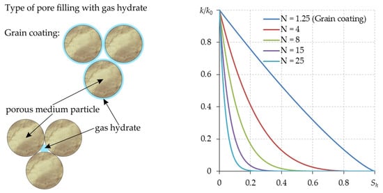
Figure 4.
Permeability of a hydrate-containing porous medium as a function of hydrate saturation at various values of the exponent N.
For pore-filling-type gas hydrates with circular cross-sections, the exponent N can be taken as equal to 5; in simple cubic packing, N can be taken equal to 25 [72]. According to the experimental data from [73,74,75] for the pore-filling type gas hydrate, the upper and lower limits of the exponent N are 15 and 3, respectively. The calculations in [57] were carried out with N equal to 8. In [70,76] N = 4 was used.
To model a specific gas hydrate field, it is necessary to conduct an experimental study to determine the parameter N, which will be the best approximated value of permeability depending on hydrate saturation.
2.4. Relative Permeabilities
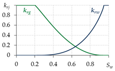
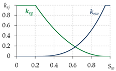
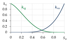
To determine the relative permeabilities for gas and water, various equations are used in different works (Table 1). The equations in the first two lines are written for two-phase filtration; that is, they do not take into account the presence of the third phase—gas hydrate. Therefore, when using them, a contradiction is possible: at Sw = 0.6, Sh = 0.35 and Sg = Sgr = 0.05, the value krg ≈ 0.2—i.e., the gas is considered mobile, although its saturation is equal to the residual, which cannot be. Thus, for the correct calculation of the relative phase permeabilities for gas and water, it is necessary to develop dependencies that take into account the presence of a third gas hydrate phase. The last row of Table 1 shows the equations from [17,56,64], adapted to take into account the presence of gas hydrate in a porous medium. Therefore, when carrying out calculations, these equations are likely to give more accurate results.

Table 1.
Calculation of relative permeabilities for gas and water.
To model a specific gas hydrate deposit, it is necessary to conduct experiments and determine specific types of relative permeability curves, as it is when modeling oil and gas fields.
2.5. Pressures of Phases
Capillary pressure pc is related to gas and water pressures as:
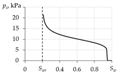
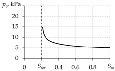
To determine the capillary pressure, various equations are used in different works (Table 2). The papers [77,86] present graphs of the experimental values of capillary pressure as functions of water saturation. The qualitative forms of these experimental curves are in better agreement with the curve obtained using the dependence from the first line of Table 2. Therefore, their use in calculations is preferable.

Table 2.
Calculation of capillary pressure.
The paper [86] presents data of capillary pressure for various samples of a porous medium. From [86], it can be seen that the order of magnitude of capillary pressure is 103–104 Pa. The order of magnitude of pressure in gas hydrate deposits is 106–107 Pa, which is 2–4 orders of magnitude more than the capillary pressure magnitude. Therefore, in a number of works [17,41,48,49,59,60,62,64,67,71,88], the capillary pressure is neglected and pc = 0 is assumed, and only one total pressure is used: p = pg = pw.
2.6. Phase-Transition Intensity
The following equations can be written for the phase transition intensities:
where G is the mass concentration of gas in the hydrate; Mj (j = g, w, h) is the molar mass of gas, water and hydrate, respectively, kg/mol; n is the hydration number; Jhg, Jhw and Jh are intensities of gas and water released from the hydrate, and the rate of gas hydrate formation, respectively—kg/(m3·s).
A phase transition can be considered as a thermodynamic equilibrium or non-equilibrium (considering the kinetics of phase transition). To consider the kinetics of gas hydrate decomposition, the following equations can be used [89]:
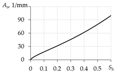
Here, kd is the molar specific rate of gas hydrate decomposition, mol/(m2·Pa·s); kd0 is the intrinsic rate constant of gas hydrate decomposition, mol/(m2·Pa·s); it does not depend on temperature, pressure or the geometry of the gas hydrate particle; ΔE is the activation energy, J/mol; R is the universal gas constant, J/(mol·K); T is temperature, K; As is the total surface area of decomposing hydrate particles per unit volume, m2/m3; feq and fg are gas fugacity at equilibrium pressure at the current temperature and gas fugacity at current pressure and temperature, respectively—Pa. For an ideal gas, the fugacity f is equal to the pressure p, and for a real gas, it can be calculated using the following expression:
where pst is the pressure at which the value of the compressibility factor zg ≈ 1—the pressure at which gas can be considered almost ideal. It can be assumed that pst = 105 Pa.
For methane hydrate, the following values are usually used:
Kim et al. (1987) [89]: kd0 = 1.24·105 mol/(m2·Pa·s); ΔE/R = 9400 ± 545 K.
Clarke and Bishnoi (2001) [90]: kd0 = 3.6·104 mol/(m2·Pa·s); ΔE/R = 9752.73 ± 29.27 K.
Referencing was performed in [90] to [89], and it was noted that the values from [90] are more accurate, so it is preferable to use them.
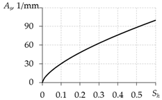
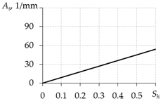
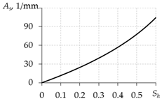
Table 3 presents the equations for calculating As from different works. The expressions presented in the last two rows of this table are more preferable, since they do not contain the free experimental parameter As0.

Table 3.
Equations for calculating As.
2.7. Equilibrium Pressure and Temperature
The following empirical equation can be used for equilibrium pressure and temperature [17,41,60,61,62,64,68,70,88,91]:
where A and B are empirical coefficients; p∗ = 1 Pa; T∗ = 1 K.
The empirical equation for the phase equilibrium of methane hydrate presented in Figure 2 can be represented in the following form [4]:

Table 4.
Coefficients for the phase equilibrium curves of methane hydrate, Equation (11) [4].
2.8. Latent Heat of Phase Transitions in the Energy Conservation Equation
The last term of Equation (7) can be written as:
The phase-transition intensities of substances into themselves are equal to zero:
If the solubility of gas in water and the evaporation (condensation) of water are not considered, then:
so (12) can be rewritten as:
It is known that during phase transitions, latent heat is released or absorbed, which can be written as follows:
or considering that Jkj = −Jjk:
where Lh is the latent specific heat of hydrate formation or decomposition, J/kg. Then (13) can be rewritten in the following form:
2.9. Non-Isothermal Filtration Parameters (Joule–Thomson Effect and Adiabatic Cooling)
To determine the Joule–Thomson coefficient (differential throttling coefficient), the following relationship can be used [92]:
After the gas density from (9) is substituted into this equation:
the partial derivative of gas compressibility factor with respect to temperature at constant pressure can be obtained using the Latonov-Gurevich Equation (10):
Then, the Joule–Thomson coefficient for the gas can finally be written as:
If the gas is considered ideal, then:
and then:
If the density of a substance is assumed to be constant (ρ = const), then it can be substituted into Equation (14), and the Joule–Thomson coefficient for an incompressible fluid can be obtained:
The adiabatic cooling coefficient is determined from this expression:
Then, for a real and ideal gas, it can be written as:
For a substance which density is assumed to be constant (ρ = const), the adiabatic cooling coefficient is equal to zero:
These parameters affect the temperature, and accordingly, the process of gas hydrate decomposition. Thus, more accurate results are obtained.
3. Conclusions
To solve practical problems related to gas hydrates, it is necessary to build mathematical models which take into account the main features of the studied processes. Such mathematical models are based upon multiphase media mechanics equations, where the system of basic equations includes the equations of continuity and conservation of momentum and energy. The paper presented the equations of conservation of mass, momentum and energy for non-isothermal flow of gas and water in a porous medium considering the formation or decomposition of gas hydrate. A model can be developed by extending these equations to the case of multicomponent filtration. For example, the gas phase can contain various gases as components (methane, carbon dioxide, etc.), whereas the liquid phase may contain dissolved gas and salts; hydrates of various gases may be present.
To carry out calculations for actual gas hydrate fields, it is first and foremost necessary to conduct field studies similar to those carried out for traditional oil and gas fields by determining the reservoir properties (porosity, saturation, permeability, relative permeability, etc.). Second, it is also necessary to carry out studies to determine the dependences of these parameters on hydrate saturation. It is also important to conduct experiments to determine the empirical parameters for the gas hydrate—in particular: composition, kinetics of gas hydrate decomposition, phase equilibrium curve, etc.
This paper presents several equations and empirical ratios used in the construction of mathematical models in different works. These equations can be used to identify the general fundamental laws of processes occurring during non-isothermal filtration of gas and water considering the decomposition of gas hydrate.
Analysis of the works devoted to the gas extraction from gas hydrate deposits showed that it is additionally necessary to solve the following problems:
- determination of relative phase permeabilities for gas and water, taking into account the presence of gas hydrate in the pores;
- gas hydrate decomposition at negative temperatures, when the hydrate decomposes into gas and ice;
- accounting for the self-preservation of gas hydrates in gas hydrate deposits.
One of the promising methods for extracting methane from gas hydrate deposits is the CH4-CO2 replacement method. In this regard, it is additionally necessary to solve the following problems:
- filtration of two-component gas (methane and carbon dioxide) and water;
- the solubility of carbon dioxide in water;
- filtration of gas, water and liquid carbon dioxide;
- replacement process: thermodynamic equilibrium or taking into account the kinetics of formation or decomposition of gas hydrates.
Author Contributions
Conceptualization, S.L.B., N.G.M. and D.S.B.; methodology, S.L.B. and D.S.B.; validation, N.G.M.; formal analysis, S.L.B., N.G.M. and D.S.B.; investigation, S.L.B. and D.S.B.; writing—original draft preparation, S.L.B., N.G.M. and D.S.B. All authors have read and agreed to the published version of the manuscript.
Funding
This research received no external funding.
Institutional Review Board Statement
Not applicable.
Informed Consent Statement
Not applicable.
Data Availability Statement
The data presented in this study are available on request from the corresponding author.
Conflicts of Interest
The authors declare no conflict of interest.
References
- Istomin, V.A.; Yakushev, V.S. Gas Hydrates in Nature; Nedra: Moscow, Russia, 1992. [Google Scholar]
- Sloan, E.D.; Koh, C.A. Clathrate Hydrates of Natural Gases, 3rd ed.; CRC Press: Boca Raton, FL, USA, 2007. [Google Scholar] [CrossRef]
- Gas Hydrates in Marine Sediments off the Oregon Coast. Available online: https://www.usgs.gov/media/images/gas-hydrates-marine-sediments-oregon-coast-0 (accessed on 2 November 2022).
- Musakaev, N.G.; Borodin, S.L. To the question of the interpolation of the phase equilibrium curves for the hydrates of methane and carbon dioxide. MATEC Web Conf. 2017, 115, 05002. [Google Scholar] [CrossRef]
- Vlasov, V.A. Mathematical model of the effect of self-preservation of gas hydrates. J. Eng. Phys. Thermophys. 2019, 92, 1406–1414. [Google Scholar] [CrossRef]
- Makogon, Y.F. Natural gas hydrates—A promising source of energy. J. Nat. Gas Sci. Eng. 2010, 2, 49–59. [Google Scholar] [CrossRef]
- Ivanov, M.G.; Chudakov, G.M.; Tereshchenko, I.A.; Polyakov, A.V.; Stepanov, M.S.; Hanyuchenko, N.D. Problems of industrial development of natural metanogidrat. Nauchnye Tr. KubGTU 2017, 2, 296–309. [Google Scholar]
- Chong, Z.R.; Yang, S.H.B.; Babu, P.; Linga, P.; Li, X.S. Review of natural gas hydrates as an energy resource: Prospects and challenges. Appl. Energy 2016, 162, 1633–1652. [Google Scholar] [CrossRef]
- Konno, Y.; Fujii, T.; Sato, A.; Akamine, K.; Naiki, M.; Masuda, Y.; Yamamoto, K.; Nagao, J. Key findings of the world’s first offshore methane hydrate production test off the coast of Japan: Toward future commercial production. Energy Fuels 2017, 31, 2607–2616. [Google Scholar] [CrossRef]
- BP Statistical Review of World Energy 2020. Available online: https://www.bp.com/content/dam/bp/business-sites/en/global/corporate/pdfs/energy-economics/statistical-review/bp-stats-review-2020-full-report.pdf (accessed on 9 September 2022).
- Resources to Reserves 2013. Available online: https://iea.blob.core.windows.net/assets/afc6bec5-22e8-4105-a1b3-ceb89eaec1e9/Resources2013.pdf (accessed on 9 September 2022).
- BP Statistical Review of World Energy 2022. Available online: https://www.bp.com/content/dam/bp/business-sites/en/global/corporate/pdfs/energy-economics/statistical-review/bp-stats-review-2022-full-report.pdf (accessed on 9 September 2022).
- Kvenvolden, K.A.; Ginsburg, G.D.; Soloviev, V.A. Worldwide distribution of subaquatic gas hydrates. Geo-Mar. Lett. 1993, 13, 32–40. [Google Scholar] [CrossRef]
- Englezos, P. Clathrate hydrates. Ind. Eng. Chem. Res. J. 1993, 32, 1251–1274. [Google Scholar] [CrossRef]
- Gudzenko, V.T.; Varenichev, A.A.; Gromova, M.P. Gazogidraty. Informacionno-analiticheskij obzor. Geol. Geophys. Dev. Oil Gas Fields 2016, 5, 39–68. (In Russian) [Google Scholar]
- Perlshtein, G.Z.; Sergeev, D.O.; Tipenko, G.S.; Tumskoy, V.E.; Khimenkov, A.N.; Vlasov, A.N.; Merzlyakov, V.P.; Stanilovskaya, Y.V. Hydrocarbon gases and permafrost of the Arctic shelf. Arct. Ecol. Econ. 2015, 2, 35–44. (In Russian) [Google Scholar]
- Popov, V.V. A mathematical model of ideal gas hydrate decomposition in a reservoir through decreasing pressure and simultaneous heating. Math. Notes NEFU 2019, 26, 83–97. [Google Scholar] [CrossRef]
- Khlystov, O.M.; Khabuev, A.V.; Belousov, O.V.; Grachev, M.A.; Nishio, S.; Sugiyama, H.; Manakov, A.Y. The experience of mapping of Baikal subsurface gas hydrates and gas recovery. Russ. Geol. Geophys. 2014, 55, 1122–1129. [Google Scholar] [CrossRef]
- Makogon, Y.F.; Omel’chenko, R.Y. Messoyaha—Gazogidratnaya zalezh’, rol’ i znachenie. Geol. I Polezn. Iskop. Mirovogo Okeana 2012, 3, 5–19. [Google Scholar]
- Hancock, S.H.; Dallimore, S.R.; Collett, T.S.; Carle, D.; Weatherill, B.; Satoh, T.; Inoue, T. Overview of pressure-drawdown production test results for the JAPEX/JNOC/GSC. Mallik 5L-38 gas hydrate production research well. In Scientific Results from the Mallik 2002 Gas Hydrate Production Well Program, Mackenzie Delta, Northwest Territories, Canada; Dallimore, S.R., Collett, T.S., Eds.; Geological Survey of Canada Bulletin 585; Canada Department of Mines and Technical Surveys: Ottawa, ON, Canada, 2005; p. 134. [Google Scholar]
- Dallimore, S.R.; Collett, T.S. Summary and implications of the Mallik 2002 gas hydrate production research well program. In Scientific Results from the Mallik 2002 Gas Hydrate Production Well Program Mackenzie Delta, Northwest Territories, Canada; Dallimore, S.R., Collett, T.S., Eds.; Geological Survey of Canada Bulletin 585; Canada Department of Mines and Technical Surveys: Ottawa, ON, Canada, 2005; pp. 1–36. [Google Scholar]
- Kurihara, M.; Funatsu, K.; Kusaka, K.; Yasuda, M.; Dallimore, S.R.; Collet, T.S.; Hancock, S.H. Well-test analysis for gas hydrate reservoirs: Examination of parameters suggested by conventional analysis for the JAPEX/JNOC/GSC. Mallik 5L-38 gas hydrate production research well. In Scientific Results from the Mallik 2002 Gas Hydrate Production Well Program Mackenzie Delta, Northwest Territories, Canada; Dallimore, S.R., Collett, T.S., Eds.; Geological Survey of Canada Bulletin 585; Canada Department of Mines and Technical Surveys: Ottawa, ON, Canada, 2005; p. 137. [Google Scholar]
- Hong, H.; Pooladi-Darvish, M. Numerical study of constant-rate gas production from in situ gas hydrate by depressurization. In Scientific Results from the Mallik 2002 Gas Hydrate Production Well Program Mackenzie Delta, Northwest Territories, Canada; Dallimore, S.R., Collett, T.S., Eds.; Geological Survey of Canada Bulletin 585; Canada Department of Mines and Technical Surveys: Ottawa, ON, Canada, 2005; p. 138. [Google Scholar]
- Ashford, D.I.; Numasawa, M.; Martin, C.K.; Yamamoto, K.; Dallimore, S.R.; Wright, J.F.; Nixon, F.M.; Applejohn, A.; Taylor, A.E. Overview of engineering and operations activities conducted as part of the JOGMEC/NRCan/Aurora Mallik 2007–2008 Gas Hydrate Production Research Well Program, Part A: 2007 field program. In Scientific Results from the JOGMEC/NRCan/Aurora Mallik 2007–2008 Gas Hydrate Production Research Well Program, Mackenzie Delta, Northwest Territories, Canada; Dallimore, S.R., Collett, T.S., Eds.; Geological Survey of Canada Bulletin 601; Canada Department of Mines and Technical Surveys: Ottawa, ON, Canada, 2012. [Google Scholar]
- Dallimore, S.R.; Wright, J.F.; Nixon, F.M.; Kurihara, M.; Yamamoto, K.; Fujii, T.; Fujii, K.; Numasawa, M.; Yasuda, M.; Imasato, Y. Geological and thermodynamic factors affecting the stimulation-response characteristics of a production test interval, Mallik 2007 gas hydrate production research well. In Proceedings of the 6th International Conference on Gas Hydrates, Vancouver, BC, Canada, 6–10 July 2008. [Google Scholar]
- Dallimore, S.R.; Wright, J.F.; Yamamoto, K.; Bellefleur, G. Proof of concept for gas hydrate production using the depressurization technique, as established by the JOGMEC/NRCan/Aurora Mallik 2007–2008 Gas Hydrate Production Research Well Program. In Scientific Results from the JOGMEC/NRCan/Aurora Mallik 2007–2008 Gas Hydrate Production Research Well Program, Mackenzie Delta, Northwest Territories, Canada; Dallimore, S.R., Yamamoto, K., Wright, J.F., Bellefleur, G., Eds.; Geological Survey of Canada Bulletin 601; Canada Department of Mines and Technical Surveys: Ottawa, ON, Canada, 2012; pp. 1–15. [Google Scholar]
- Kurihara, M.; Funatsu, K.; Ouchi, H.; Sato, A.; Yasuda, M.; Yamamoto, K.; Fujii, T.; Numasawa, M.; Narita, H.; Masuda, Y.; et al. Analysis of the JOGMEC/NRCan/Aurora Mallik gas hydrate production test through numerical simulation. In Proceedings of the 6th International Conference on Gas Hydrates, Vancouver, BC, Canada, 6–10 June 2008. [Google Scholar]
- Yamamoto, K.; Kanno, T.; Wang, X.-X.; Tamaki, M.; Fujii, T.; Chee, S.-S.; Wang, X.-W.; Pimenovd, V.; Shako, V. Thermal responses of a gas hydrate-bearing sediment to a depressurization operation. RSC Adv. 2017, 7, 5554–5577. [Google Scholar] [CrossRef]
- Borodin, S.L.; Belskikh, D.S. The current state of researches related to the extraction of methane from a porous medium containing hydrate. Bull. Tyumen State Univ. Phys. Math. Model. Oil Gas Energy 2018, 4, 131–147. [Google Scholar] [CrossRef]
- Uchida, S.; Klar, A.; Yamamoto, K. Sand production model in gas hydrate-bearing sediments. Int. J. Rock Mech. Min. Sci. 2016, 86, 303–316. [Google Scholar] [CrossRef]
- Ohgaki, K.; Takano, K.; Sangawa, H.; Matsubara, T.; Nakano, S. Methane exploitation by carbon dioxide from gas hydrates phase equilibria for CO2–CH4 mixed hydrate system. J. Chem. Eng. Jpn. 1996, 29, 478–483. [Google Scholar] [CrossRef]
- Hirohama, A.; Shimoyama, Y.; Wakabayashi, A.; Tatsuta, S.; Nishida, N. Conversion of CH4-hydrate to CO2-hydrate in liquid CO2. J. Chem. Eng. Jpn. 1996, 29, 1014–1020. [Google Scholar] [CrossRef]
- Lee, H.; Seo, Y.; Seo, Y.T.; Moudrakovski, I.L.; Ripmeester, J.A. Recovering methane from solid methane hydrate with carbon dioxide. Angew. Chem. Int. Ed. Engl. 2003, 42, 5048–5051. [Google Scholar] [CrossRef]
- Lee, B.R.; Koh, C.A.; Sum, A.K. Quantitative measurement and mechanisms for CH4 production from hydrates with the injection of liquid CO2. Phys. Chem. Chem. Phys. 2014, 16, 14922–14927. [Google Scholar] [CrossRef]
- Ota, M.; Morohashi, K.; Abe, Y.; Watanabe, M.; Smith, R.L., Jr.; Inomata, H. Replacement of CH4 in the hydrate by use of liquid CO2. Energy Convers. Manag. 2005, 46, 1680–1691. [Google Scholar] [CrossRef]
- Ota, M.; Abe, Y.; Watanabe, M.; Smith, R.L., Jr.; Inomata, H. Methane recovery from methane hydrate using pressurized CO2. Fluid Phase Equilibria 2005, 229, 553–559. [Google Scholar] [CrossRef]
- Qing, Y.; Qing, Y.; Sun, C.; Liu, B.; Xue, W.; Ma, Z.-W.; Ma, Q.; Yang, L.-Y.; Chen, G.; Li, Q.; et al. Methane recovery from natural gas hydrate in porous sediment using pressurized liquid CO2. Energy Convers. Manag. 2013, 67, 257–264. [Google Scholar] [CrossRef]
- Zhou, X.; Fan, S.; Liang, D.; Dua, J. Determination of appropriate condition on replacing methane from hydrate with carbon dioxide. Energy Convers. Manag. 2008, 49, 2124–2129. [Google Scholar] [CrossRef]
- Goel, N. In situ methane hydrate dissociation with carbon dioxide sequestration: Current knowledge and issues. J. Pet. Sci. Eng. 2006, 51, 169–184. [Google Scholar] [CrossRef]
- Zhang, Y.; Xiong, L.J.; Li, X.S.; Chen, Z.Y.; Xu, C.G. Replacement of CH4 in hydrate in porous sediments with liquid CO2 injection. Chem. Eng. Technol. 2014, 37, 2022–2029. [Google Scholar] [CrossRef]
- Poveshchenko, Y.A.; Podryga, V.O.; Popov, I.V.; Popov, S.B.; Rahimly, P.I.; Kazakevich, G.I. Numerical simulation in problems with dissociation of gas hydrates in a porous medium in one-dimensional formulation. Uchenye Zap. Kazan. Univ. Seriya Fiz. -Mat. Nauk. 2019, 161, 205–229. [Google Scholar] [CrossRef]
- Maksimov, A.M.; Yakushev, V.S.; Chuvilin, E.M. Otsenka vozmozhnosti vybrosov gaza pri razlozhenii gazovyh gidratov v plaste. Transactions (Doklady) of the Russian Academy of Sciences. Earth Sci. Sect. 1997, 352, 532–534. [Google Scholar]
- Vasil’eva, Z.A.; Efimov, S.I.; Yakushev, V.S. Prediction of thermal interaction between oil/gas wells and permafrost rocks containing metastable gas hydrates. Earths Cryosphere 2016, 20, 65–69. [Google Scholar]
- Sergienko, V.I.; Lobkovskii, L.I.; Semiletov, I.P.; Dudarev, O.V.; Dmitrievskii, N.N.; Shakhova, N.E.; Romanovskii, N.N.; Kosmach, D.A.; Nikol’skii, D.N.; Nikiforov, S.L.; et al. The degradation of submarine permafrost and the destruction of hydrates on the shelf of east arctic seas as a potential cause of the “Methane Catastrophe”: Some results of integrated studies in 2011. Dokl. Earth Sci. 2012, 446, 1132–1137. [Google Scholar] [CrossRef]
- Giavarini, C.; Maccioni, F. Self-preservation at low pressure of methane hydrates with various gas contents. Ind. Eng. Chem. Res. 2004, 43, 6616–6621. [Google Scholar] [CrossRef]
- Nakai, S. Development of Natural Gas Hydrate (NGH) Supply Chain. In Proceedings of the 25th World Gas Conference, Kuala Lumpur, Malaysia, 4–8 June 2012; pp. 3040–3050. [Google Scholar]
- Semenov, M.E.; Shic, E.Y.; Safronov, A.F. Issledovanie osobennostej iskusstvennogo polucheniya gidratov metana i ehtana v usloviyah svobodnoj konvekcii. Gazohimiya 2011, 1, 18–23. (In Russian) [Google Scholar]
- Khasanov, M.K.; Stolpovsky, M.V. Injection of sulfur dioxide in a finite layer, initially saturated with methane and water. News Tula State Univ. Sci. Earth 2020, 3, 325–334. [Google Scholar] [CrossRef]
- Khasanov, M.K.; Kil’dibaeva, S.R. Mathematical model of gas hydrate formation of sulfur dioxide by injecting liquid sulfur dioxide into a layer saturated with methane and water. Vestn. Udmurt. Univ. Mat. Mekhanika Komp’yuternye Nauk. 2020, 30, 125–133. [Google Scholar] [CrossRef]
- Veluswamy, H.P.; Kumar, A.; Seo, Y.; Lee, J.D.; Linga, P. A review of solidified natural gas (SNG) technology for gas storage via clathrate hydrates. Appl. Energy 2018, 216, 262–285. [Google Scholar] [CrossRef]
- Carroll, J. Natural Gas Hydrates: A Guide for Engineers; Gulf Professional Publishing: Houston, TX, USA, 2020. [Google Scholar] [CrossRef]
- Hammerschmidt, E.G. Formation of gas hydrates in natural gas transmission lines. Ind. Eng. Chem. 1934, 26, 851–855. [Google Scholar] [CrossRef]
- Shagapov, V.S.; Musakaev, N.G.; Khabeev, N.S.; Bailey, S.S. Mathematical modelling of two-phase flow in a vertical well considering paraffin deposits and external heat exchange. Int. J. Heat Mass Transf. 2004, 47, 843–851. [Google Scholar] [CrossRef]
- Li, S.; Li, Y.; Yang, L.; Han, Y.; Jiang, Z. Prediction of equilibrium conditions for gas hydrates in the organic inhibitor aqueous solutions using a thermodynamic consistency-based model. Fluid Phase Equilibria 2021, 544-545, 113118. [Google Scholar] [CrossRef]
- Nigmatulin, R.I. Dynamics of Multiphase Media; Hemisphere Publ. Corp.: New York, NY, USA, 1991. [Google Scholar]
- Basniev, K.S.; Kochina, I.N.; Maksimov, V.M. Underground Fluid Mechanics; Nedra: Moscow, Russia, 1993. (In Russian) [Google Scholar]
- Zhang, P.; Liu, B.; Hu, L.; Meegoda, J.N. Coupled multiphase flow and pore compression computational model for extraction of offshore gas hydrates. Comput. Geotech. 2022, 145, 104671. [Google Scholar] [CrossRef]
- Klar, A.; Soga, K.; Ng, M.Y.A. Coupled deformation–flow analysis for methane hydrate extraction. Géotechnique 2010, 60, 765–776. [Google Scholar] [CrossRef]
- Musakaev, N.G.; Borodin, S.L.; Gubaidullin, A.A. Methodology for the Numerical Study of the Methane Hydrate Formation During Gas Injection into a Porous Medium. Lobachevskii J. Math. 2020, 41, 1272–1277. [Google Scholar] [CrossRef]
- Stolpovsky, M.V.; Chiglintseva, A.S.; Kochanova, E.Y. Features of porous medium heating while gas hydrates formation. Probl. Gather. Treat. Transp. Oil Oil Prod. 2020, 6, 55–63. [Google Scholar] [CrossRef]
- Stolpovsky, M.V.; Chiglintseva, A.S.; Kochanova, E.Y. On the process of gas hydrate formation in a porous medium saturated with methane and ice. Probl. Gather. Treat. Transp. Oil Oil Prod. 2020, 6, 64–75. [Google Scholar] [CrossRef]
- Musakaev, N.G.; Khasanov, M.K. Solution of the Problem of Natural Gas Storages Creating in Gas Hydrate State in Porous Reservoirs. Mathematics 2020, 8, 36. [Google Scholar] [CrossRef]
- Tsypkin, G.G. Formation of hydrate in injection of liquid carbon dioxide into a reservoir saturated with methane and water. Fluid Dyn. 2016, 51, 672–679. [Google Scholar] [CrossRef]
- Bondarev, E.A.; Rozhin, I.I.; Popov, V.V.; Argunova, K.K. Underground Storage of Natural Gas in Hydrate State: Primary Injection Stage. J. Eng. Thermophys. 2018, 27, 221–231. [Google Scholar] [CrossRef]
- Moridis, G.J.; Sloan, E.D. Gas production potential of disperse low-saturation hydrate accumulations in oceanic sediments. Energy Convers. Manag. 2007, 48, 1834–1849. [Google Scholar] [CrossRef]
- Latonov, V.V.; Gurevich, G.R. Calculation of the compressibility factor of natural gas. Gas Ind. 1969, 2, 7–9. (In Russian) [Google Scholar]
- Khasanov, M.K.; Rafikova, G.R.; Musakaev, N.G. Mathematical Model of Carbon Dioxide Injection into a Porous Reservoir Saturated with Methane and its Gas Hydrate. Energies 2020, 13, 440. [Google Scholar] [CrossRef]
- Shagapov, V.S.; Chiglintseva, A.S.; Shepelkevich, O.A. Numerical simulation of hydrate formation at injection cold gas in the snow massif. Math. Models Comput. Simul. 2019, 11, 690–703. [Google Scholar] [CrossRef]
- Konno, Y.; Masuda, Y.; Hariguchi, Y.; Kurihara, M.; Ouchi, H. Key factors for depressurization-induced gas production from oceanic methane hydrates. Energy Fuels 2010, 24, 1736–1744. [Google Scholar] [CrossRef]
- Liang, W.; Wang, J.; Li, P. Gas production analysis for hydrate sediment with compound morphology by a new dynamic permeability model. Appl. Energy 2022, 322, 119434. [Google Scholar] [CrossRef]
- Sakamoto, Y.; Komai, T.; Miyazaki, K.; Tenma, N.; Yamaguchi, T.; Zyvoloski, G. Laboratory-scale experiments of the methane hydrate dissociation process in a porous media and numerical study for the estimation of permeability in methane hydrate reservoir. J. Thermodyn. 2010, 2010, 452326. [Google Scholar] [CrossRef]
- Dai, S.; Seol, Y. Water permeability in hydrate-bearing sediments: A pore-scale study. Geophys. Res. Lett. 2014, 41, 4176–4184. [Google Scholar] [CrossRef]
- Sakamoto, Y.; Komai, T.; Kawamura, T.; Minagawa, H.; Tenma, N.; Yamaguchi, T. Laboratory-scale experiment of methane hydrate dissociation by hot-water injection and numerical analysis for permeability estimation in reservoir: Part 1, Numerical study for estimation of permeability in methane hydrate reservoir. Int. J. Offshore Polar 2007, 17, 47–56. [Google Scholar]
- Kumar, A.; Maini, B.; Bishnoi, P.R.; Clarke, M.; Zatsepina, O.; Srinivasan, S. Experimental determination of permeability in the presence of hydrates and its effect on the dissociation characteristics of gas hydrates in porous media. J. Pet. Sci. Eng. 2010, 70, 114–122. [Google Scholar] [CrossRef]
- Johnson, A.; Patil, S.; Dandekar, A. Experimental investigation of gas-water relative permeability for gas-hydrate-bearing sediments from the Mount Elbert Gas Hydrate Stratigraphic Test Well, Alaska North Slope. Mar. Pet. Geol. 2011, 28, 419–426. [Google Scholar] [CrossRef]
- Xuefei, S.; Kishore, K.M. Kinetic simulation of methane hydrate formation and dissociation in porous media. Chem. Eng. Sci. 2006, 61, 3476–3495. [Google Scholar] [CrossRef]
- Van Genuchten, M.T. A closed-form equation for predicting the hydraulic conductivity of unsaturated soils. Soil Sci. Soc. Am. J. 1980, 44, 892. [Google Scholar] [CrossRef]
- Jang, J.; Santamarina, J.C. Evolution of gas saturation and relative permeability during gas production from hydrate-bearing sediments: Gas invasion vs. gas nucleation. J. Geophys. Res. Solid Earth 2014, 119, 116–126. [Google Scholar] [CrossRef]
- Hong, H.; Pooladi-Darvish, M. Simulation of depressurization for gas production from gas hydrate reservoirs. J. Can. Pet. Technol. 2005, 44, 39–46. [Google Scholar] [CrossRef]
- Hirasaki, G.J. Sensitivity Coefficients for History Matching Oil Displacement Processes. Soc. Pet. Eng. J. 1975, 15, 39–49. [Google Scholar] [CrossRef]
- Zhu, H.; Xu, T.; Xin, X.; Yuan, Y.; Jiang, Z. Numerical investigation of natural gas hydrate production performance via a more realistic three-dimensional model. J. Nat. Gas Sci. Eng. 2022, 107, 104793. [Google Scholar] [CrossRef]
- Chen, X.; Du, X.; Yang, J.; Gao, D.; Zou, Y.; He, Q. Developing offshore natural gas hydrate from existing oil & gas platform based on a novel multilateral wells system: Depressurization combined with thermal flooding by utilizing geothermal heat from existing oil & gas wellbore. Energy 2022, 258, 124870. [Google Scholar] [CrossRef]
- Lei, H.; Yang, Z.; Xia, Y.; Yuan, Y. Prospects of gas production from the vertically heterogeneous hydrate reservoirs through depressurization in the Mallik site of Canada. Energy Rep. 2022, 8, 2273–2287. [Google Scholar] [CrossRef]
- Dong, B.C.; Xiao, P.; Sun, Y.F.; Kan, J.Y.; Yang, M.K.; Peng, X.W.; Sun, C.Y.; Chen, G.J. Coupled flow and geomechanical analysis for gas production from marine heterogeneous hydrate-bearing sediments. Energy 2022, 255, 124501. [Google Scholar] [CrossRef]
- Moridis, G.J.; Silpngarmlert, S.; Reagan, M.T.; Collett, T.; Zhang, K. Gas production from a cold, stratigraphically-bounded gas hydrate deposit at the Mount Elbert Gas Hydrate Stratigraphic Test Well, Alaska North Slope: Implications of uncertainties. Mar. Pet. Geol. 2011, 28, 517–534. [Google Scholar] [CrossRef]
- Brooks, R.H.; Corey, A.T. Hydraulic Properties of Porous Media. Hydrology Papers. Colorado State University, Fort Collins, CO, USA, 1964; p. 3. [Google Scholar]
- Wang, Q.; Wang, Z.; Li, P.; Song, Y.; Wang, D. Numerical modeling of coupled behavior of gas production and mechanical deformation of gas hydrate reservoir in Shenhu area, South China Sea: Enlightenments for field monitoring and model verification. Energy 2022, 254, 124406. [Google Scholar] [CrossRef]
- Kazakevich, G.I.; Poveschenko, Y.A.; Podryga, V.O.; Rahimly, P.I.; Bakeer, A.E.; Abu-Nab, A.K. Mathematical modeling of dissociation of gas hydrates in porous medium taking into account ice and salt. Keldysh Inst. Prepr. 2022, 11, 26. [Google Scholar] [CrossRef]
- Kim, H.C.; Bishnoi, P.R.; Heidemann, R.A.; Rizvi, S.S.H. Kinetics of methane hydrate decomposition. Chem. Eng. Sci. 1987, 42, 1645–1653. [Google Scholar] [CrossRef]
- Clarke, M.; Bishnoi, P.R. Determination of the activation energy and intrinsic rate constant of methane gas hydrate decomposition. Can. J. Chem. Eng. 2001, 79, 143–147. [Google Scholar] [CrossRef]
- Shagapov, V.S.; Yumagulova, Y.A.; Musakaev, N.G. Theoretical study of the limiting regimes of hydrate formation during contact of gas and water. J. Appl. Mech. Tech. Phys. 2017, 58, 189–199. [Google Scholar] [CrossRef]
- Chekalyuk, E.B. Oil Reservoir Thermodynamics; Nedra: Moscow, Russia, 1965. (In Russian) [Google Scholar]
Publisher’s Note: MDPI stays neutral with regard to jurisdictional claims in published maps and institutional affiliations. |
© 2022 by the authors. Licensee MDPI, Basel, Switzerland. This article is an open access article distributed under the terms and conditions of the Creative Commons Attribution (CC BY) license (https://creativecommons.org/licenses/by/4.0/).
