Abstract
The paper aims to identify the situations in which a complex elastic system, which is subject to mechanical vibrations, can act as a dynamic absorber of vibrations for certain frequencies. The conditions that the system must fulfill in order to achieve this goal are determined and then a calculation example is presented. The method is interesting because it allows to avoid attaching an absorber specially built for this, a situation that complicates the project and increases manufacturing costs.
MSC:
70J30; 70J35
1. Introduction
Dynamic absorbers represent an ingenious and relatively cheap solution to reduce vibrations, with numerous applications in engineering, from civil engineering, mechanical engineering, vehicles, aeronautics, naval engineering and the examples can go on. The first dynamic absorber was patented by Frahm [1] in 1909. The theoretical foundations are laid by the work of Ormondroyd and Den Hartog [2] in 1928. Taking into account the performance of this vibration reduction system and the low manufacturing price, numerous studies followed in this field. The aim was to increase the effectiveness of the designed absorbers and to optimize the various constructive parameters. Numerous improvements have also been proposed and numerous types of unconventional absorbers, active or passive, have been created. At the moment, the dynamic absorber is still finding new applications, in new fields, requiring a continuous study of the subject.
For example, a dynamic absorber that attenuates the vibrations of three resonance frequencies simultaneously is studied and proposed in [3]. It is known to suppress a disturbing frequency it is sufficient to install a single damper whose natural frequency is adjusted to the excitation frequency. Obviously, to suppress more frequencies, more absorbers can be mounted, but this approach leads to additional costs and a more complicated device. The paper presents a system that allows, by adjusting the geometric dimensions, the precise adjustment of the natural frequency of the absorber according to the value of the frequency to be absorbed. Numerical examples prove the validity of the proposed solution. In [4], a nonlinear dynamic vibration absorber (DVA) with variable frequency and damping is analyzed. Numerical simulation for this vibration absorber for a coupled system with two degrees of freedom shows that the proposed absorber can adapt to different conditions that may occur in operation. For the seismic impact protection of a building, in [5] a DVA with several frequencies is proposed in the form of an elastic continuum. This material has several natural frequencies in the frequency range of seismic effects. When the absorber has several natural frequencies close to the resonant frequency of the protected building, part of the building’s oscillation energy is transferred to the absorber’s oscillations and the peak level of the frequency response function is reduced. A specific problem is presented in [6] where a DVA is designed to help prevent the overturning of a rigid block. For this, a pendulum shock absorber is used. Variable parameters are considered geometric characteristics. The results prove that the existence of DVA leads to a general improvement of the dynamic response of the system. The experimental results confirm the validity of the analytical model and validate the effectiveness of the pendulum mass damper.
DVA are mainly used for the damping of forced vibrations with harmonic excitation. One or more harmful frequencies are usually eliminated. Interesting research that uses magnetic force to achieve dynamic absorption is presented in [7]. Vibration control in rotating systems is studied. Two Jeffcott rotor vibration absorption systems are proposed. For the first version, the shock absorber is located between the absorber mass and the disc, and in the second, it is located between the absorber mass and the ground. The optimal parameters of the absorption system are obtained analytically using the classical theory. To evaluate and validate the obtained results, the experimental data of the proposed dynamic absorbers were compared with the simulation results. The effectiveness of the proposed solution was thus verified.
Devices operating at supercritical speeds need to go through all speeds, including the critical ones, during start-up. Passing through the resonance zone can lead to machine failures, if the amplitude level when passing through the resonance is too high. This raises the problem of designing some DVA that will act during the passage of the car through the critical speeds. For this, in [8] a rotating dynamic absorber with a viscoelastic element is proposed. A finite element modeling is used in the dimensioning step. A significant reduction of the amplitudes and requests that occur when passing through the critical zone is obtained. Thus, the rotating system can reach a super-critical speed through a smooth run-up.
New methods as use of the magneto-rheological elastomer (a smart materials with elastic property variable in the external magnetic field) were developed in the last period to absorb the vibration energy [9,10]. In the paper [11], two versions of a possible semi-active suspension of a work machine seat are presented. The first version uses a magneto-rheological damper and the second a combination of magneto-rheological damper and passive dynamic absorber. The optimum of the passive parameters of the seat suspension and the dynamic absorber was obtained using genetic algorithms according to the defined minimization function. In [12,13] various aspects of the design of DVA were studied. More results are presented in [14,15,16,17,18,19,20].
Although most works deal with the introduction of special elements to achieve dynamic absorption, the calculation methods involved can be very useful in the development of our work. We present some such works that helped us in the development of the proposed ideas below.
In the case of boring processes, it is necessary to reduce the excessive vibrations caused by the low rigidity of the material of the tools used [21]. Vibration reduction is achieved using a DVA, located on the edge of the boring bar. The dynamic absorber is represented by a thin steel tube inside which there is natural rubber. Tuning the DVA to the vibration that is desired to be absorbed is achieved by varying the number of inserted rubber sleeves. Thus a customized design of the drill rod with DVA can remain stable at higher forces.
In [22], a new e-DVA module is proposed that signals the synergy that exists between vehicle driving and vibration attenuation. This allows the design of a mechanism that ensures the tuning of the absorber in relation to the excitation of the road. An analysis of the vertical dynamics in the frequency and time domain demonstrates the increase in comfort while driving and the stability of handling. This synergy represented a suggestion regarding the use of a judicious design in order to use the mechanical system as a mechanical absorber. In the paper [23], a new method is proposed to allow the optimal configuration of the DVA attached to a non-damped/damped primary structure. Based on the Lyapunov equation, the performance indices are expressed by quadratic matrix forms. Using this method, the classical solutions can be obtained in the case of an external force or an excitation by acceleration of the base. More interesting method to calculate the vibration absorbtion of a mechanical system are presented in [24,25,26,27].
In the current work, it is studied to what extent a judicious dimensioning of a system allows it to function as a dynamic absorber, for one or more exciting frequencies. In this way, a reduction of vibrations on certain frequency ranges can be ensured, without mounting an additional absorber. In this way, the design of the elastic system is simplified and, obviously, the manufacturing costs decrease. The complexity of the system and the large number of parameters involved allow that by changing some of these parameters, a dynamic absorption can be obtained for the mass that is of interest to the user, without adding a dedicated absorber.
2. Model and Method
For simplicity, let’s consider a vibrating system, without damping, with degrees of freedom. It is also assume that the system is subject to a harmonic excitation with pulsation . The equations of motion for this system are given by the system of differential equations [28,29,30,31]:
where represents the mass matrix, represents the stifness matyrix and the excitation forces vector. Let’s also assume that the excitation acts on a single element of the system, let’s say on the element n. It is desired that the system as a whole act as a dynamic shock absorber, that is, p masses not to move if the excitation acts. Let’s assume that these are the last p masses in the system (this can be achieved, regardless of the masses we focus on, by renumbering the masses). We propose to determine the condition that the masses and rigidities of the system must fulfill for this to happen. Let’s partition the system of equations as follows:
where the vector contains the first n-p masses of the system (has dimension (n − p) × 1 and the next p masses (has dimension (p × 1). The matrices , have dimension ((n − p) × (n − p), matrices matricele , have dimension (n − p) × p, the matrices , have the dimension p × (n − p), and also , the dimension p × p. The solution is chosen in the form:
One obtain:
Putting the condition that the solution (3) verifies Equation (2), it obtains:
or:
In the conditions in which (there is no excitation on the first part of the system) it is impose that . Let’s look for the conditions for this to happen. By entering the conditions in Equation (6), we get:
It is denoted:
In order for the first system to admit a non-zero solution, it must have the condition:
which represents a first condition.
Suppose that we have determined a normalized solution of system (7), denote it by Then any vector is a solution of system (7) and system (8) can be written:
Equation (11) represents a system of p conditions that must be respected in order to have rest of the p bodies. λ can be eliminated if is multiplied Equation (11) by .
It results λ:
Introducing into Equation (12) it obtains:
From this set (Equation (14)) of p conditions only p − 1 are now independent. Now there are 1 + p − 1 = p conditions that must be respected by the parameters of the system, so p masses (in our case the last p numebered) remain in rest.
Let’s now deal with the most common case in practice, namely the one where we have a work machine that, powered by a motor (usually electric) that rotates at a speed ω, and it desired it to work without vibrating. So we want to dynamically isolate a single mass mn and then p = 1. The matrix has size (n − 1)x(n − 1), the vector has only one element F, the condition that the geometric, mass and elastic quantities must fulfill are given by (to have zero displacement of mass n at frequency ω). So: ,
In order for the first system to admit a non-zero solution, it must to have condition (10), which in this case is the only condition that must be fulfilled.
It is assumed that it was determined a normalized solution of system (16), denote it by . Then any vector is a solution of system (16) and system (17) can be written:
which provides , therefore also provides the amplitudes of the forced oscillations of the other n − 1 flywheels.
The cases in which there is not damping do not exist in practice. In any engineering system there are frictions and processes through which the energy of the system is dissipated. Let’s then analyze a system in which it is considered that there is a viscous damping. From the point of view of the obtained results, all the previous considerations remain valid from a qualitative point of view. The difference lies in the fact that the phases of the oscillations of the different masses are different. Also, the number of parameters involved is higher, additional damping properties appear, but from the point of view of the proposed purpose, this represents an advantage, the number of parameters that can be varied increases, so the possibilities of tuning the system to reduce unwanted frequencies increase.
System (1) becomes in this case:
There are different forms for the matrix , but in what follows this is not important. The harmonic solution that must check the system (19) is:
It obtains, successively:
By partitioning the matrices, in accordance with the previous considerations, it obtains:
By introducing this solution into system (19), it obtains:
or:
Since Equation (24) must be valid at any time, this equation is equivalent to the following two systems:
or:
It can obtain and the harmonic solution:
The notation:
is made. Solution (29) can also be written:
where:
Imposing the conditions (there is no excitation on the first part of the system) and the solution . it obtain:
which represent the conditions that must be met to obtain a maximum absorption of vibrations for the masses n − p + 1, n − p + 2, …, n.
3. Results and Discussion
Through a careful dimensioning of the system, it can also play the role of a dynamic shock absorber, without the need to add an additional element.
A simple example will illustrate this. Consider an elastic system presented in Figure 1 made up of 6 flywheels, linked together with elastic elements having known stiffness. Flywheels can have rotational movement. An exciting moment acts on the last flywheel. It results the problem of determining the conditions for which, under the action of this excitation, flywheel 4 stays in place, without vibrating. The number of DOF for this system is six.
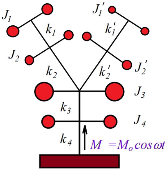
Figure 1.
Elastic system with wheels.
The equations of motion for this system are:
It is noted:
If it is considered a harmonic solution and put the condition that this solution verifies the system of differential equations, it obtains:
where the amplitude of the harmonic oscillations is found in the vector: . It must to find the condition for which: . The determinant of the system is:
The values considered in the applications are:
kgm2; kgm2; kgm2; kgm2; kgm2;
kgm2; N·m/rad; N·m/rad;
N·m/rad; N·m/rad and the excitation moment N·m.
The condition leads to the pulsation:
A graph of the function from condition (9) where it can follow the values where this condition is fulfilled is represented in Figure 2. The values obtained in Table 1 can be seen.
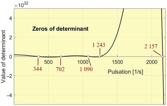
Figure 2.
The representation of the function .

Table 1.
The frequencies at which absorption occurs to flywheel 6.
The five values obtained for the considered data represent frequencies for which, upon excitation with a harmonic moment with an amplitude of 100 Nm acting on flywheel 6, a total vibration absorption is obtained at this flywheel (in the case of zero damping). If there is damping, the absorption is very high around these determined values. So we note that for a complex system, there are several eigenpulsations at which vibration absorption can be done. If the system has many components, then the number of excitation frequencies that can be absorbed increase. In Figure 3 it can be seen the amplitude of the forced vibrations at different excitation frequencies.
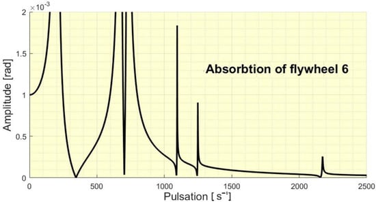
Figure 3.
The absorbtion of the flywheel 6.
If one refer to flywheel 5, then the condition that it absorbs vibrations gives us the five frequencies that will be absorbed, presented in the Table 2.
Table 2.
The frequencies at which absorption occurs to flywheel 5.
In Figure 4 it can be seen the amplitude of the forced vibrations at different pulsations/excitation frequencies of the flywheel 5.
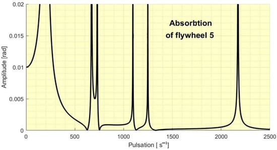
Figure 4.
The absorbtion of the flywheel 5.
In a similar way the Figure 5, Figure 6, Figure 7 and Figure 8 presents us the absorbtion of the flywheel 4, 3, 2 and 1.
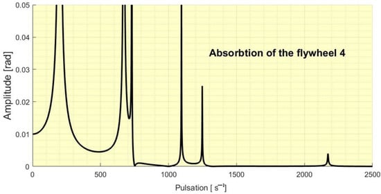
Figure 5.
The absorbtion of the flywheel 4.
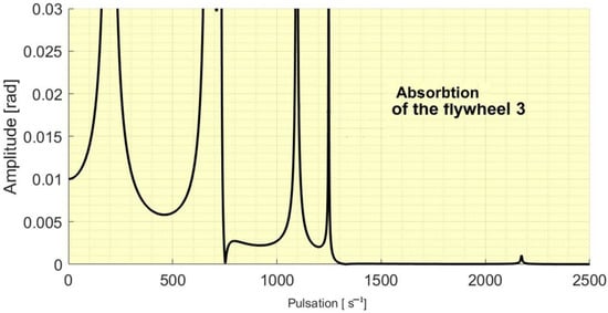
Figure 6.
The absorbtion of the flywheel 3.
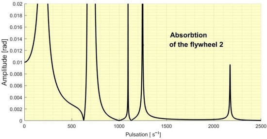
Figure 7.
The absorbtion of the flywheel 2.
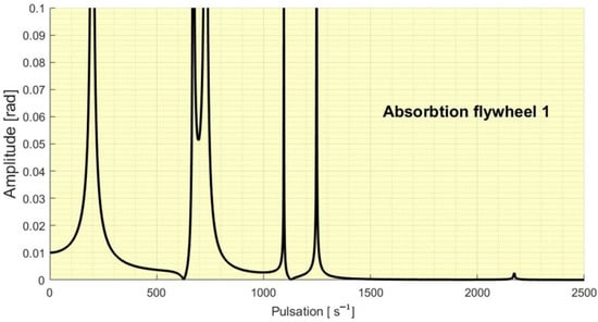
Figure 8.
The absorbtion of the flywheel 1.
The eigenpulsations of the system are presented in the Table 3.
Table 3.
The eigenpulsations of the system.
In Figure 9 are presented the amplitude of the all six flywheel overlapped.
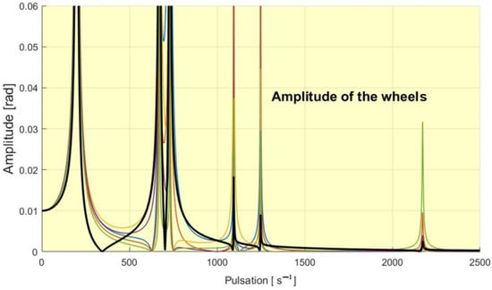
Figure 9.
The amplitudes of the flywheels overlapped. With black is the graph for the flywheel 6.
Figure 10 shows the interval of pulsations that ensure the rest of the flywheel six. For each value of the moment of inertia for flywheel two, five pulsations are obtained for which the total vibration absorption of this flywheel takes place.
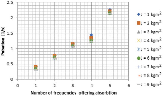
Figure 10.
The intervals of pulsations that ensure the rest of the flywheel 6 for different moment of inertia of the flywheel 2.
A comparison with a system with a simplified system having four flywheels (Figure 11) is presented in Figure 12. In Figure 13 are presented the behavior of all flywheels. The number of the DOF in this case is four.
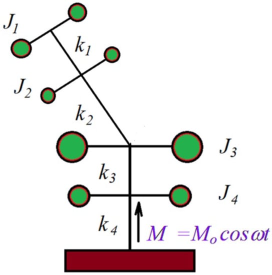
Figure 11.
Elastic system with four wheels.
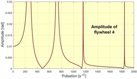
Figure 12.
The absorbtion of the flywheel 4 for the simplified system.
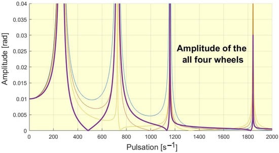
Figure 13.
The amplitudes of the flywheels for the simplified system overlapped.
Consider now a damping introduce in the system in the form: . In Figure 14 are presented the amplitude of forced vibration considering different damping coefficient.
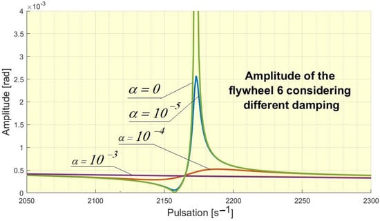
Figure 14.
Effect of damping on the amplitude of the flywheel 6.
4. Conclusions
Dynamic absorbers represent one of the most spectacular methods of reducing vibrations. The main advantage is its simplicity and the low price with which vibration absorption can be ensured. In the work, the authors wanted to show that, in the case of complex elastic systems, with several vibrating masses, dynamic absorption can be ensured without introducing additional systems, by properly designing the system, so that certain parts of it are dynamic absorbers for other parties. The more complex the system, the more possibilities for dynamic absorption there are. Moreover, for complex systems, the number of exciting frequencies for which dynamic absorption can be achieved is more numerous. So for a judiciously dimensioned system, dynamic absorption can be achieved, so without major expenses, for frequency intervals, useful in practice.
In other words, a judicious design of an elastic system allows managing the problem of resonance frequencies without using special devices, such as DVA, an operation that requires a redesign and the attachment of an expensive device. In this way, the price of realizing a dynamic absorption drops a lot. Also, the installation of an absorber in the system leads to the modification, which in certain cases can become important, of the vibration response of the entire system. By the method described in the paper, the modification of the system’s behavior is avoided due to the addition of some DVA.
An example shows these properties that complex dynamic systems can provide. A possibility of development of the subject is the construction of algorithms that offer the optimal solution for different practical applications.
Author Contributions
Conceptualization, M.L.S. and M.M.; methodology, M.L.S. and M.M.; software, M.L.S., M.M. and S.V.; validation, M.L.S., M.M. and S.V.; formal analysis, M.L.S., M.M. and S.V.; investigation, M.L.S., M.M. and S.V.; resources, M.L.S., M.M. and S.V.; data curation, M.L.S., M.M. and S.V.; writing—original draft preparation, M.L.S.; writing—review and editing, M.L.S., M.M. and S.V.; visualization, M.L.S., M.M. and S.V.; supervision, M.M. and S.V.; project administration, M.L.S., M.M. and S.V.; funding acquisition, M.L.S., M.M. and S.V. All authors have read and agreed to the published version of the manuscript.
Funding
This research received no external funding. The APC was funded by Transilvania University of Brasov.
Institutional Review Board Statement
Not applicable.
Informed Consent Statement
Not applicable.
Data Availability Statement
Not applicable.
Conflicts of Interest
The authors declare no conflict of interest.
References
- Frahm, H. Device for Damping Vibrations of Bodies. U.S. Patent US989958A, 30 October 1909. [Google Scholar]
- Ormondroyd, J.; Den Hartog, J.P. Theory of the dynamic vibration absorber. Trans. ASME 1928, 50, 9–22. [Google Scholar]
- Yoon, G.H.; Choi, H.; So, H.Y. Development and optimization of a resonance-based mechanical dynamic absorber structure for multiple frequencies. J. Low Freq. Noise Vib. Act. Control 2021, 40, 880–897. [Google Scholar] [CrossRef]
- Wang, T.; Tian, R.L.; Yang, X.W.; Zhang, Z.W. A Novel Dynamic Absorber with Variable Frequency and Damping. Shock Vib. 2021, 2021, 8833089. [Google Scholar] [CrossRef]
- Makarov, S.B.; Pankova, N.V. On the Possibility of Applying a Multi-frequency Dynamic Absorber (MDA) to Seismic Protection Tasks. Adv. Intell. Syst. Comput. 2020, 1127, 395–403. [Google Scholar] [CrossRef]
- Di Egidio, A.; Alaggio, R.; Aloisio, A.; de Leo, A.M.; Contento, A.; Tursini, M. Analytical and experimental investigation into the effectiveness of a pendulum dynamic absorber to protect rigid blocks from overturning. Int. J. Non-Linear Mech. 2019, 115, 1–10. [Google Scholar] [CrossRef]
- Heidari, H.; Monjezi, B. Vibration control of imbalanced Jeffcott rotor by virtual passive dynamic absorber with optimal parameter values. Proc. Inst. Mech. Eng. Part C J. Mech. Eng. Sci. 2018, 232, 4278–4288. [Google Scholar] [CrossRef]
- Fontes, Y.C.; Nicoletti, R. Rotating dynamic absorber with viscoelastic element. J. Braz. Soc. Mech. Sci. Eng. 2016, 38, 377–383. [Google Scholar] [CrossRef]
- Komatsuzaki, T.; Inoue, T.; Terashima, O. A broadband frequency-tunable dynamic absorber for the vibration control of structures. In Proceedings of the 13th International Conference on Motion and Vibration Control (MOVIC), Southampton, UK, 3–6 July 2016; Volume 744, p. 012167. [Google Scholar] [CrossRef]
- Komatsuzaki, T.; Inoue, T.; Iwata, Y. MRE-based adaptive-tuned dynamic absorber with self-sensing function for vibration control of structures. In Proceedings of the 7th Annual ASME Conference on Smart Materials, Adaptive Structures and Intelligent Systems (SMASIS), Newport, RI, USA, 8–10 September 2014; Volume 1, p. V001T03A011. [Google Scholar]
- Orecny, M.; Segl’a, S.; Hunady, R.; Ferkova, Z. Application of a magneto-rheological damper and a dynamic absorber for a suspension of a working machine seat. Procedia Eng. 2014, 96, 338–344. [Google Scholar] [CrossRef]
- Nicoara, D.D. The Damped Dynamic Vibration Absorber—A Numerical Optimization Method. In Proceedings of the International Conference COMAT 2018, Brasov, Romania, 25–26 October 2018. [Google Scholar]
- Pennestri, E. An application of Chebyshev’s min-max criterion to the optimum design of a damped dynamic vibration absorber. J. Sound Vib. 1998, 217, 757–765. [Google Scholar] [CrossRef]
- Diveyev, B.; Horbay, O.; Kernytskyy, I.; Cherchyk, H.; Burtak, V. 52 DVA for the MEMS Devices. In Proceedings of the International Conference on Perspective Technologies and Methods in MEMS Design (MEMSTECH), Polyana, Ukraine, 22–26 May 2019; IEEE Book Series; IEEE: Piscataway, NJ, USA, 2019; pp. 52–55. [Google Scholar]
- Song, J.; Si, P.; Hua, H.; Li, Z. A DVA-Beam Element for Dynamic Simulation of DVA-Beam System: Modeling, Validation and Application. Symmetry 2022, 14, 1608. [Google Scholar] [CrossRef]
- Byrnes, P.W.G.; Lacy, G. Modal vibration testing of the DVA-1 radio telescope. In Ground-Based and Airborne Telescopes VI, Proceedings of the SPIE Astronomical Telescopes + Instrumentation, Edinburgh, UK, 26 June–1 July 2016; Book Series; SPIE: Paris, France, 2016; Volume 9906, Part 1, p. 99063P. [Google Scholar] [CrossRef]
- Sharma, S.K.; Sharma, R.C.; Lee, J.; Jang, H.L. Numerical and Experimental Analysis of DVA on the Flexible-Rigid Rail Veicle Carbody Resonant Vibration. Sensors 2022, 22, 1922. [Google Scholar] [CrossRef]
- De Oliveira, D.B.P.; Coelho, J.P.; Sanches, L.; Michon, G. Dynamics of Helicopters with DVA Under Structural Uncertainties. In Proceedings of the DINAME 2017, São Sebastião, Brazil, 5–10 March 2017; Book Series, Lecture Notes in Mechanical Engineering; Springer: Berlin, Germany, 2019; pp. 111–123. [Google Scholar] [CrossRef]
- Dong, G.; Xiaojie, C.; Jing, L.; Peiben, W.; Zhengwei, Y.; Xingjian, J. Theoretical modeling and optimal matching on the damping property of mechatronic shock absorber with low speed and heavy load capacity. J. Sound Vib. 2022, 535, 117113. [Google Scholar] [CrossRef]
- Dong, G.; Xingjian, J.; Hui, S.; Li, J.; Junjie, G. Test and simulation the failure characteristics of twin tube shock absorber. Mech. Syst. Signal Process. 2019, 122, 707–719. [Google Scholar]
- Hendrowati, W.; Merdekawan, N. Modeling and analysis of boring bar vibration response in internal turning due to variation of the amount of DVA rubber in finish boring cut. J. Mech. Sci. Technol. 2021, 35, 4353–4362. [Google Scholar] [CrossRef]
- Gu, C.; Zhu, J.; Chen, X. A Novel E-DVA Module Synthesis Featuring of Synergy between Driving and Vibration Attenuation. Shock Vib. 2016, 2016, 8464317. [Google Scholar] [CrossRef]
- Du, D. Analytical solutions for DVA optimization based on the lyapunov equation. J. Vib. Acoust. Trans. ASME 2008, 130, 054501. [Google Scholar] [CrossRef]
- Abouelregal, A.E.; Marin, M. Thesize-dependent thermoelastic vibrations of nanobeams subjected to harmonic excitation and rectified sine wave heating. Mathematics 2020, 8, 1128. [Google Scholar] [CrossRef]
- Mocanu, S.; Rece, L.; Burlacu, A.; Florescu, V.; Rontescu, C.; Modrea, A. Novel Procedures for Sustainable Design in Structural Rehabilitation on Oversized Metal Structures. Metals 2022, 12, 1107. [Google Scholar] [CrossRef]
- Diveyev, B.; Dorosh, I.; Cherchyk, H.; Burtak, V.; Ostashuk, M.; Hlobchak, M.; Kotiv, M. DVA for the High-Rise Object. In Proceedings of the 16th Intenational Conference on Experience of Designing and Application of CAD Systems in Microelectronics—CADSM, Lviv, Ukraine, 22–26 February 2021. [Google Scholar] [CrossRef]
- Vlase, S.; Marin, M.; Scutaru, M.L.; Munteanu, R. New analytical method based on dynamic response of planar mechanical elastic systems. AIP Adv. 2017, 7, 1–15. [Google Scholar]
- Vlase, S.; Nastac, C.; Marin, M.; Mihalcica, M. A Method for the Study of the Vibration of Mechanical Bars Systems with Symmetries. Acta Tech. Napoc. Ser. Appl. Math. Mech. Eng. 2017, 60, 539–544. [Google Scholar]
- Vlase, S.; Marin, M.; Iuliu, N. Finite Element Method-Based Elastic Analysis of Multibody Systems: A Review. Mathematics 2022, 10, 257. [Google Scholar] [CrossRef]
- Bencze, A.; Scutaru, M.L.; Marin, M.; Vlase, S.; Toderiță, A. Adder Box Used in the Heavy Trucks Transmission Noise Reduction. Symmetry 2021, 13, 2165. [Google Scholar] [CrossRef]
- Scutaru, M.L.; Vlase, S.; Marin, M.; Modrea, A. New analytical method based on dynamic response of planar mechanical elastic systems. Bound. Value Probl. 2020, 2020, 104. [Google Scholar] [CrossRef]


Publisher’s Note: MDPI stays neutral with regard to jurisdictional claims in published maps and institutional affiliations. |
© 2022 by the authors. Licensee MDPI, Basel, Switzerland. This article is an open access article distributed under the terms and conditions of the Creative Commons Attribution (CC BY) license (https://creativecommons.org/licenses/by/4.0/).