Article

Inspection Interval Optimization for Aircraft Composite Tail Wing Structure Using Numerical-Analysis-Based Approach

1
Department of Mechanical, Robotics and Energy Engineering, Dongguk University-Seoul, 30 Pil-dong 1 Gil, Jung-gu, Seoul 04620, Korea
2
Department of Aerospace & Mechanical Engineering, Korea Aerospace University, Gyeonggi-do, Goyang-si 10540, Korea
*
Author to whom correspondence should be addressed.
Mathematics 2022, 10(20), 3836; https://doi.org/10.3390/math10203836
Submission received: 20 September 2022 / Revised: 12 October 2022 / Accepted: 14 October 2022 / Published: 17 October 2022
(This article belongs to the Special Issue Modeling and Simulation in Engineering, 2nd Edition)

Abstract

:
Recently, there has been a tremendous increase in the use of fiber-reinforced composite (FRCP) in the aviation and aerospace industries due to its superior properties of high strength, stiffness, and low weight. The most important feature of implementing composite materials in aviation is their behavior under dynamic loads and resistance to fatigue. To predict the life of composite structures and optimize the inspection interval, it is essential to predict the damage behavior of composites. In this study, a model of fatigue delamination damage of composite specimens was first constructed using a finite element analysis (FEA)-based approach. The FEA modeling was verified through comparison with experimental specimen data, and the verified FEA model was applied to the composite material aircraft tail wing structure. In this case, a Monte Carlo simulation (MCS) was performed by building a response surface model while considering the uncertainty of the mechanical parameters. Through this process, the risk as a function of flight time could be quantitatively evaluated, and the inspection interval was optimized by selecting the combination with the lowest number of repeated inspections that met the permitted risk criteria.

1. Introduction

To ensure the safe and continuous operation of aircraft, maintenance is a key activity [1]. Efficient maintenance can save high maintenance costs and can increase the service life of aircraft structures. Recently, the development of the structural health monitoring approach (condition-based maintenance) has enabled maintenance engineers to more frequently monitor the health condition of aircraft structures [2]. For this purpose, additional sensors are embedded in structures to provide health information, thus making condition-based maintenance more expensive than scheduled maintenance. Therefore, the practice of scheduled maintenance remains more dominant than condition-based maintenance. The main challenge in scheduled maintenance is the determination of efficient inspection intervals to reduce maintenance costs and maintain high safety standards [3].
The proportion of FRCPs in aircraft structures is increasing every year as the technical limitations of composite materials are gradually resolved [4]. FRCPs offer high stiffness, high strength-to-weight ratio, and excellent fatigue performance, making them suitable for the manufacturing of complex aircraft composite structures. Aircraft industries, such as Boeing 787 and Airbus A380, are using composite materials for their primary structures, such as the fuselage skin and wing spars [5]. Unlike metals, these composites suffer from complex damage mechanisms because of their anisotropic properties. Among these, fatigue delamination and debonding damage are the major causes of failure in composites [6,7,8]. During aircraft flight, fatigue load continuously occurs, thus making the structures more susceptible to fatigue delamination damage [9]. Therefore, for the accurate prediction of the life span of composite structures, it is important to predict the fatigue delamination damage.
The commonly applied maintenance method in the aviation industry is the maintenance steering group 3 (MSG-3) [10], which aids in determining the inspection interval of aircraft structures. However, MSG-3 has the disadvantage of being heavily dependent on engineering experience, while the functional/structural detail evaluation of various new composite aircraft structures is limited. Therefore, the use of MSG-3 is inadequate for direct application to composite structures. Furthermore, it is difficult to maintain structural uniformity in composites because of the inaccuracies of the manufacturing process and the random variation in properties in composites. Therefore it is challenging to predict the failure of composite materials using the traditional deterministic approaches [11]. The usage of deterministic approaches results in the underutilization of the composite material. To utilize the material to its full capacity without compromising its structural safety, the uncertainties in the composite material should be considered for its realistic design, which is not possible in deterministic analysis. Probabilistic analysis offers a solution of incorporating the uncertainties in the design variables to compute the inherent risk in a structure subjected to service loading conditions. Therefore probabilistic approaches [12,13,14] have received considerable attention when it comes to addressing the uncertainty in design and maintenance.
Recently, Dinis et al. [15] proposed a probabilistic-design-based approach for aircraft maintenance and repair. The approach employed the usage of a Bayesian network to cope with the uncertainty in both scheduled and unscheduled maintenance. A real dataset based on 372 aircraft industrial maintenance projects was used. Similarly, Chen et al. developed an approach for the optimization of inspection intervals for composite structures for dent and delamination damage. The idea was to quantify the structural residual strength and maintenance cost for the different inspection intervals. The proposed approach was implemented on an aircraft wing. A historical dataset from the Chinese aircraft industry was used to develop the proposed approach. A POD curve created using general visual inspection (GVI) and detailed inspection (DET) data was selected as a method of damage detection. The probability of detecting damage according to dent damage was calculated using a Monte Carlo simulation. From these simulation results, a procedure for calculating the optimal inspection cycle that considered the structural reliability and maintenance cost was presented. However, the main limitation of this approach was that it was based on the actual repair data after the damage was confirmed. The approach did not consider the cause and progression of the delamination and dent damage.
Similarly, Dinggiang et al. [11] developed an optimized inspection interval approach by considering dent and delamination damage. The study used the maintenance records of 12 aircraft over 10 years of operation time. Impact damage was considered the main cause of damage, and the average expected number of impacts per year was calculated by comparing the maintenance history of such impact damage and the service life of the aircraft. The failure probability of the structure was calculated by simulating the residual strength and damage growth of the structure according to the impact damage that occurred during the service life operation. This study also utilized the actual maintenance data. The limitations of this approach were the limited damage data and that it was difficult to obtain the damage maintenance data from the aircraft industry. Further, the obtained data included the information after the damage occurred, and lacked information on the damage progression and the accurate cause of the damage. To overcome the data availability problem and the lack of progressive damage knowledge, an FEA-based approach can be used. Gianella et al. [16] developed a probabilistic framework for fatigue reliability assessment by considering multi-source uncertainties. The sensitivity of each input variable was obtained, and the influence of the variable on the life prediction was derived. The above-presented literature approaches are all based on real aircraft maintenance and damage data. However, the main limitation of the approaches available in the literature is the availability of real aircraft maintenance data to develop structural health monitoring approaches for the prediction of the fatigue life of the composite structures. The acquisition of the real damage data requires the embedding of additional sensors on the skin of aircraft structures, thus making the maintenance strategies more expensive. Therefore, to overcome the unavailability of the real-life operating data problem, this study proposed a methodology that uses the FEA-based model for the generation of fatigue damage growth curves and further implements this approach for the risk assessment and optimization of the inspection interval of the KT-100 aircraft tail wing structure. To the authors’ best knowledge, no such study can be found in the literature that utilized a finite-element-analysis-based approach for the inspection interval optimization of aircraft composite structures.
In this study, a novel FEA-based approach was proposed for the inspection interval optimization of an aircraft composite tail wing structure. First, the FEA-based fatigue delamination model was constructed for the composite specimen and was verified through comparison with experimental data. The verified FEA model was extended to the composite aircraft tail wing structure of a KT-100 aircraft (Korea Aerospace Industries, Ltd., KAI). In this case, a Monte Carlo simulation was performed by building a response surface model that considered the uncertainty of the mechanical parameters. Through this process, the risk according to each flight time could be quantitatively evaluated, and the inspection interval was optimized by selecting the combination with the lowest number of repeated inspections within the conditions that met the permitted risk criteria.

2. Proposed Finite-Element-Analysis-Based Inspection Interval Optimization Approach

Figure 1 shows the proposed FEA-based inspection interval optimization approach. The developed methodology consisted of the following five phases:
Phase 1.
The geometry, fatigue-loading spectrum data, and skin-debonding damage case scenario of the KT-100 aircraft tail wing structure were obtained from KAI.
Phase 2.
A fatigue delamination damage model was developed for a simple composite specimen and extended to the full-scale aircraft tail wing geometry.
Phase 3.
The uncertainty of mechanical parameters was included, and the design of experiments was created based on Latin hypercube sampling (LHS) scenarios.
Phase 4.
A Monte Carlo simulation was performed by building a response surface model.
Phase 5.
Risk assessment and inspection interval optimization of the tail wing structure were undertaken.

2.1. Development of the Finite Element Model

Modern aircraft structures, such as the wings and fuselage, utilize FRCPs. The composite laminates are highly susceptible to delamination, which is considered one of the major damage mechanisms in composites among all other types of damage. The delamination propagation can occur under the fatigue loading, thus causing stiffness and gradual strength degradation and leading to catastrophic failure of composite structures. Therefore, the characterization of the fatigue delamination resistance in composite materials is necessary for their damage tolerance design and reliability assessment. In aircraft composite structures, stringers are joined to the skin via adhesive bonding. During the flight, cyclic fatigue causes separation between the skin and stringer, which may result in delamination failure. Therefore, it is important to predict fatigue delamination initiation and propagation so that these composite panels do not fail prematurely. To enhance the fatigue life and reliability of composite structures, several researchers have investigated the delamination growth in composites under fatigue loading. A variety of models are proposed in the literature for the prediction of fatigue delamination growth at the coupon level. However, the prediction of fatigue delamination in complex geometries, such as aircraft wing structures, is still an open issue. The most popular approach for the characterization of fatigue crack growth is Paris’ law [17,18,19]. Paris’ law relates the fatigue crack growth rate to the stress intensity factor and energy release rate. Equation (1) shows the basic form of Paris’ law [20]:
d A / d N = C f ( G ) m
where C and m represent the fitting parameters and f(G) is a function of the energy release rate (G). In metals, the stress intensity factor variation (ΔK) is usually adopted for fatigue crack growth. On the other hand, in composite laminated structures, the energy release rate (ΔG) variation seems to provide a better description of experimental results, as shown in Equation (2):
d A d N = C ( Δ G ) m = C ( G m a x G m i n )
The FE model implemented in this study and included in the FE code ABAQUS [21] was built on Equation (2) to estimate the fatigue crack growth rate.
In a numerical model, delamination is usually modeled using a damage mechanics or fracture mechanics approach in combination with Paris’ law. Different approaches are found in the literature in the context of damage mechanics. Among these, the cohesive zone modeling approach [22,23,24] received considerable attention for delamination modeling. This approach provides good results in combination with Paris’ law for simple geometries and test specimens. However, this approach is not suitable for complex geometries. On the other hand, the virtual crack closure technique (VCCT) [9,25] derived from fracture mechanics is found built into several commercial FE codes. This approach is suitable for implementation in complex geometries and can simulate fatigue delamination growth in combination with Paris’ law. The fatigue crack growth in an ABAQUS simulation employs VCCT criteria to compute the energy release rate. The crack propagation starts when the criterion based on Equation (3) is satisfied:
f = N c 1 Δ G c 2 G m a x > G t h
where N is the current cycle number and c1 and c2 are fitting parameters that are experimentally determined. Once the onset criterion is satisfied, the fatigue delamination growth rate is governed by Paris’ law, which is shown in Equation (4):
d A d N = c 3 ( Δ G ) c 4
where c3 and c4 are fitting parameters.
The fatigue delamination finite element was first implemented for the double cantilever beam (DCB) composite specimen. The results of the numerical model were compared with the benchmark experimental study [23,26]. The composite specimen had a length of 254 mm and a width of 25 mm. The thickness of each arm was 3 mm. The initial delamination was induced in the specimen with a length of 51 mm and was located in the center of the plies, as shown in Figure 2. The specimen consisted of a T300/1076 carbon fiber epoxy composite with 24 unidirectional plies.
The material properties used in the numerical model were taken from [26] and are shown in Table 1.
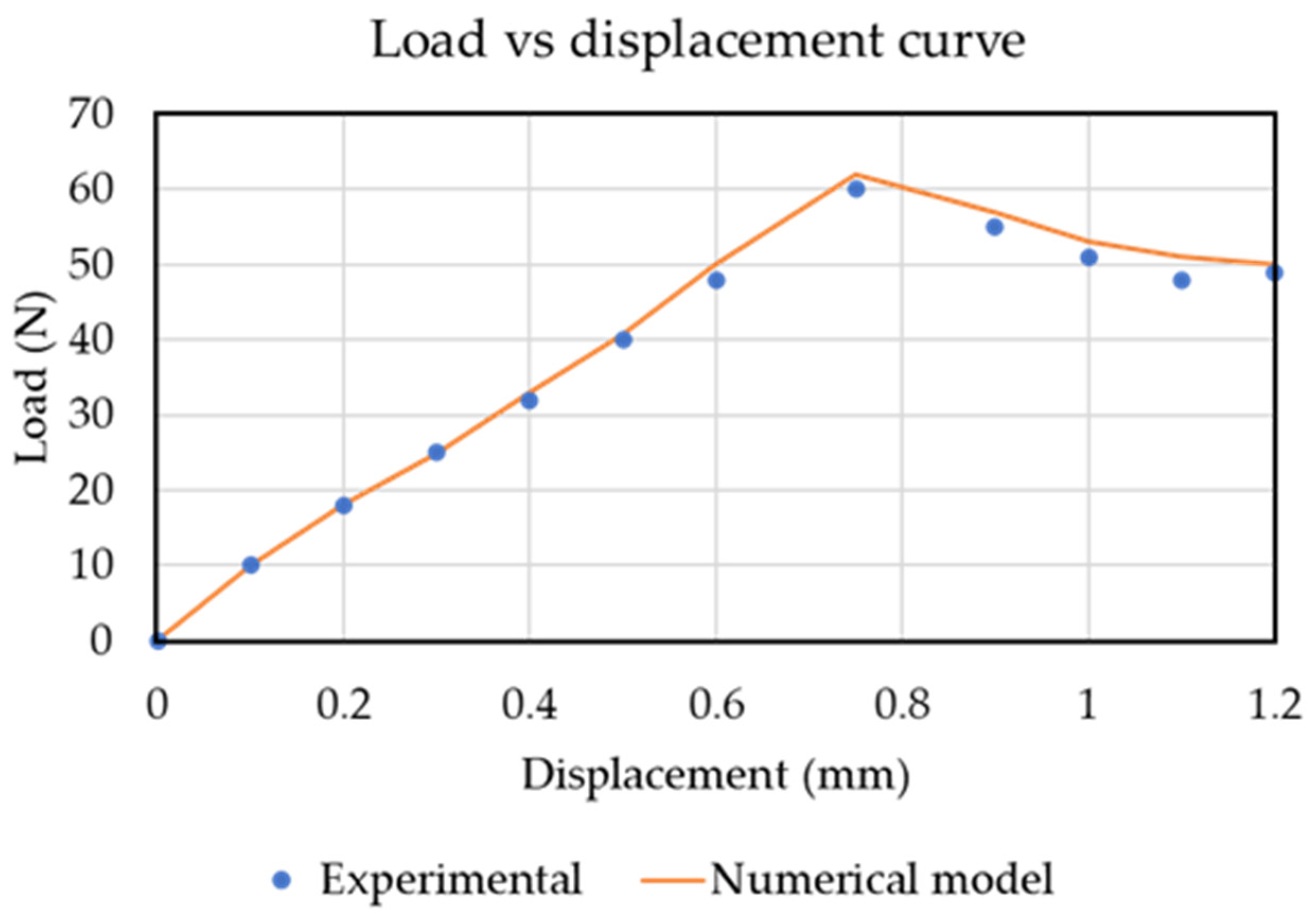
Continuum shell elements (SC8R) were used for the modeling of the DCB specimen. A single element is used throughout the thickness of each arm. The refined mesh was used in the damage propagation zone and the remaining region consisted of a coarse mesh. First, the load–displacement curve was computed for quasi-static loading. The simulation curve was computed and compared with the experimental benchmark case study result, as shown in Figure 3. The numerical model showed a linear response and a good correlation was found, both in terms of the initial stiffness and peak load between the numerical model results and the experimental benchmark case study.
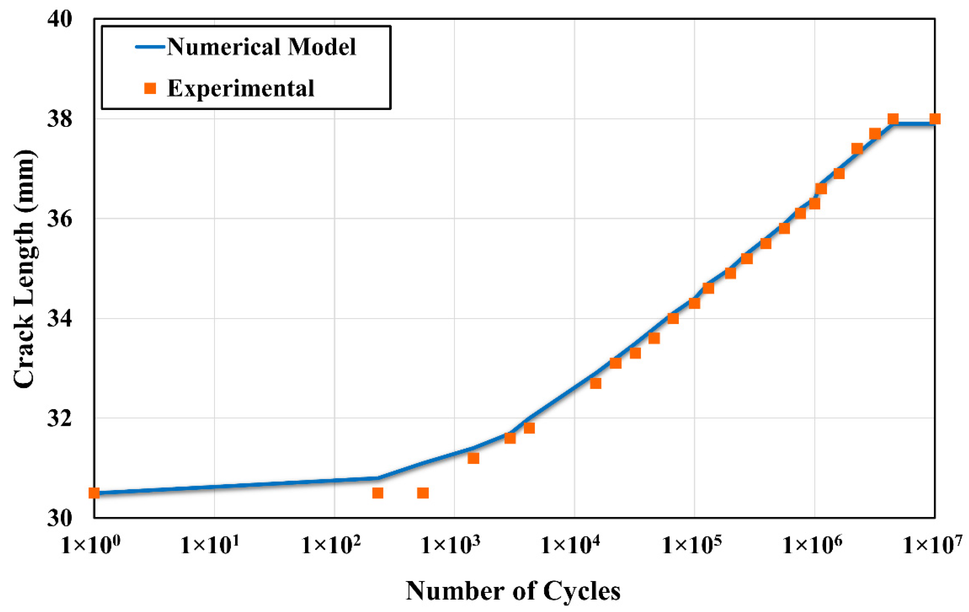
For the fatigue crack propagation analysis, the triangular load cycle as applied in the experimental benchmark case study [23,26] was applied as a fatigue loading cycle. As expected, the delamination length increased rapidly at the start of the loading cycles. The delamination stopped propagating at around 3.7 million cycles. The numerical results computed in ABAQUS showed good agreement with the experimental benchmark results, as shown in Figure 4.
Once the fatigue delamination crack propagation model was established, the model was extended from the composite specimen to the KT-100 aircraft tail wing structure. The tail wing is located behind the main lifting surface of the aircraft and provides stability and control. The design of the KT-100 horizontal stabilizer consists of upper and lower skins. The upper and lower skins of the sandwich structure act as a spur structure. The upper and lower skins are bonded and tightened to make a box-shaped structure. Three ribs exist inside the box structure. Skin debonding from the rib is the most critical damage that can occur in an aircraft tail wing structure. Figure 5 shows skin-debonding damage. Therefore, in this study, skin/rib-debonding damage was modeled using the fatigue progressive damage model.
The geometry of the tail wing was provided by the Korean Airforce and imported from the 3D model in ABAQUS. To simplify the model, bolts and rivets were not considered in the geometry. Initial delamination of 32 mm was introduced between the middle rib and upper skin, as shown in Figure 6a. To avoid the loss of computational power, shell elements (S4R) were used to model the tail wing structure with 49,209 total elements. The mesh was kept refined in the crack propagation region and coarse in the remaining regions, as shown in Figure 6b.
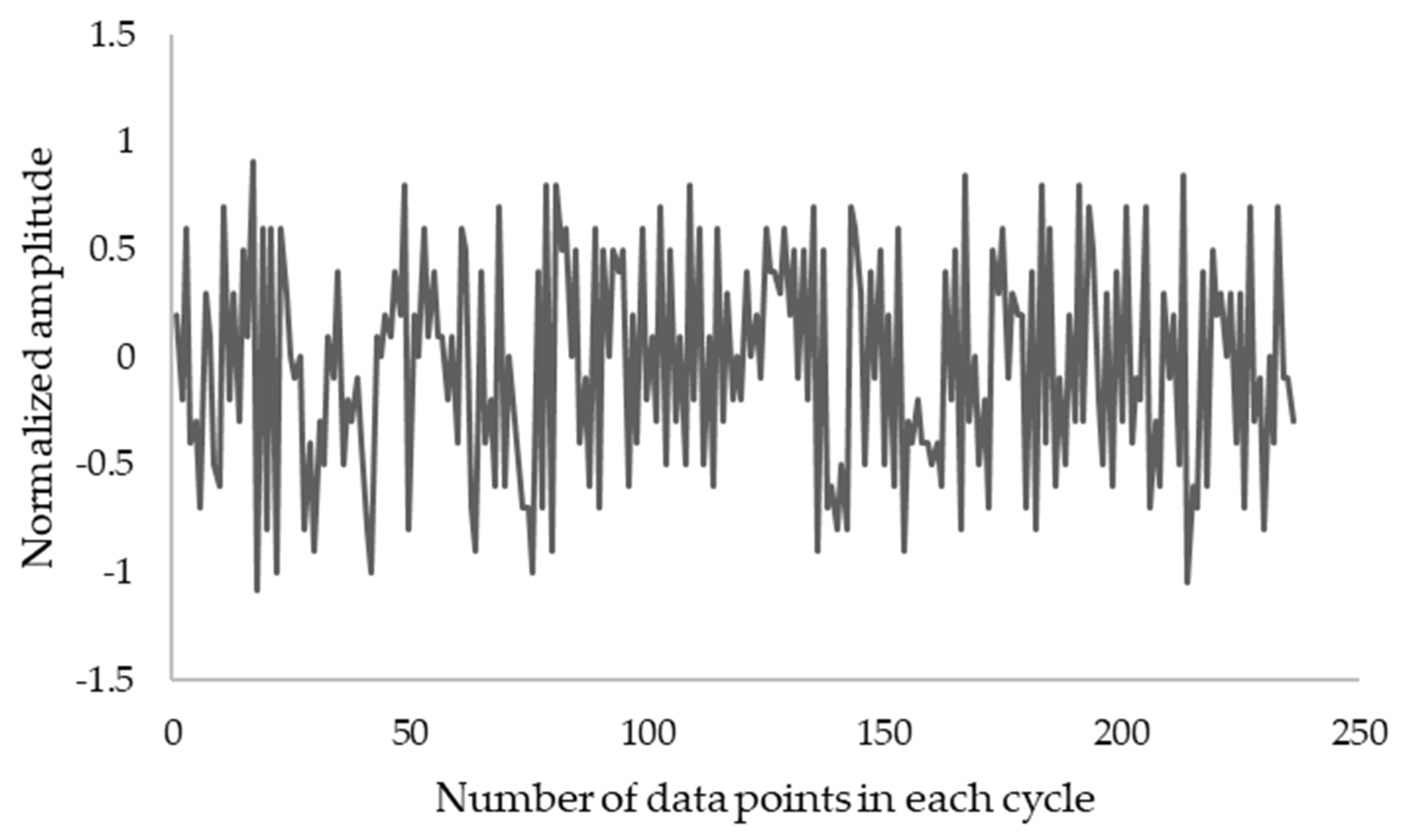
The loads and boundary conditions are used as in an actual flight scenario. One side of the wing was kept fixed, and the shear forces were applied at the other end with the flight loading spectrum as a fatigue cycle provided by the Korean Airforce. Figure 7 shows the flight operating loading spectrum with a normalized amplitude.
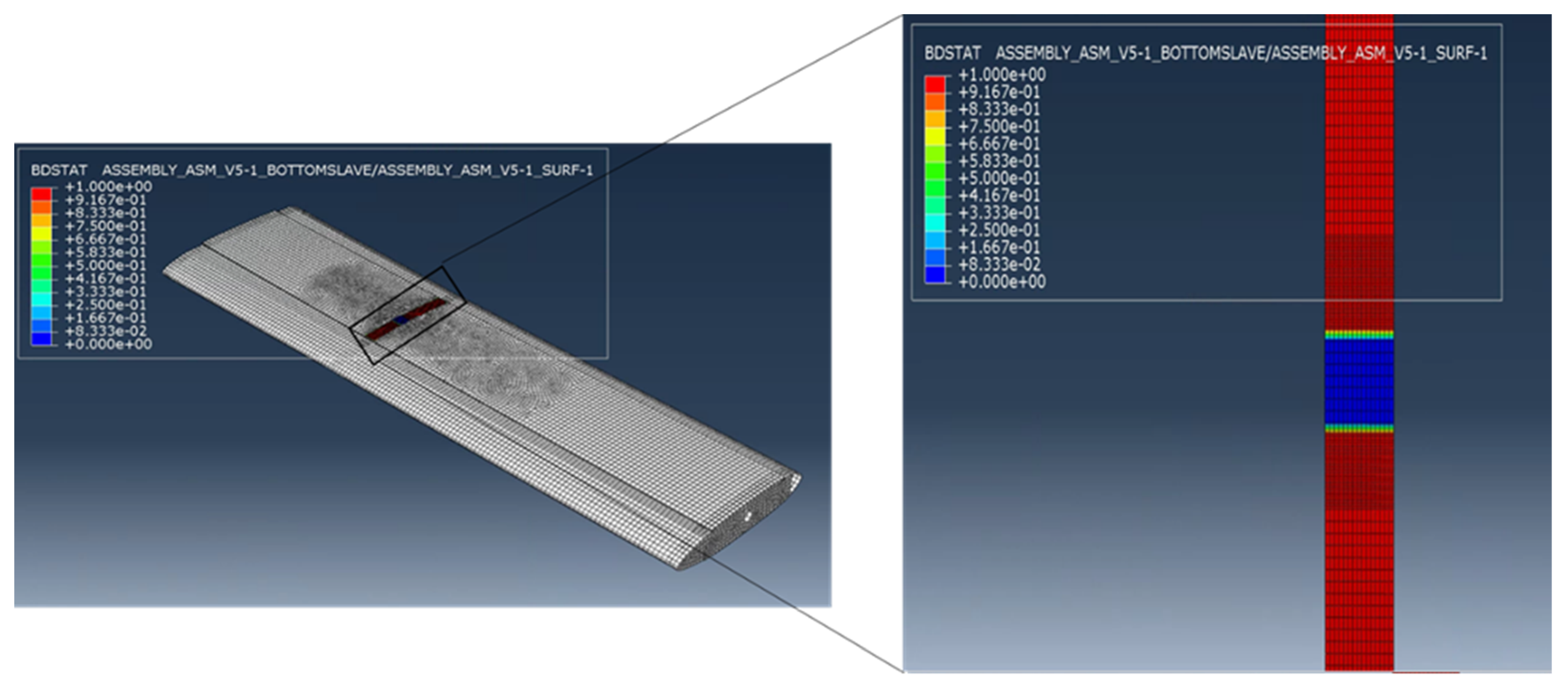
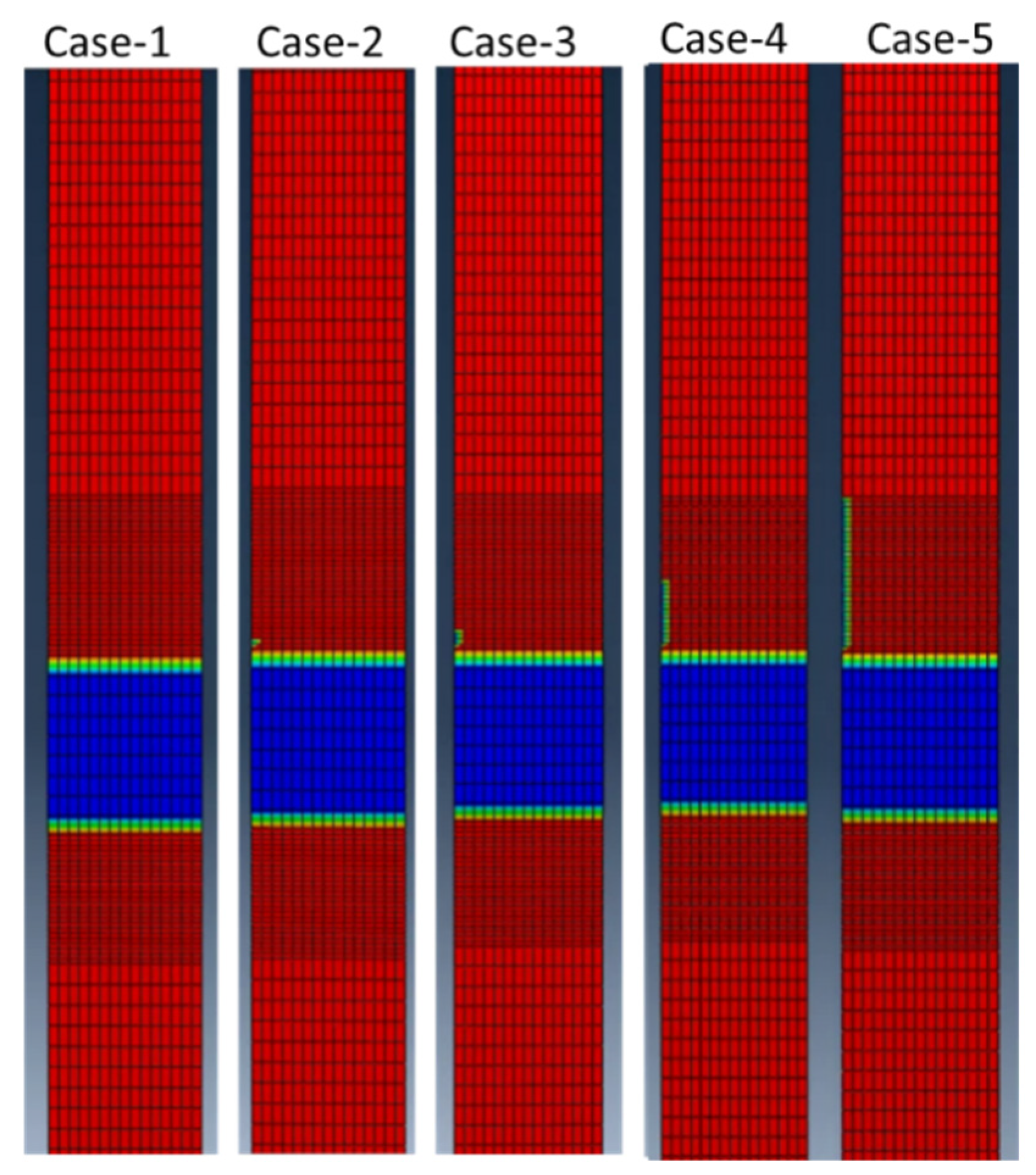
The bond stat plot (crack propagation plot) output in ABAQUS represents the fatigue crack propagation. The blue color represents the unbonded region, while the red color represents the bonded region. Figure 8 represents the BDSTAT plot for the tail wing structure. The BDSTAT plot was computed between the upper skin and the middle rib of the composite structure.
Different case simulations were carried out for the different values of the applied loading scenarios by using the flight operating load spectrum. The simulation was run for 8000 flight hours (FHs), and the crack propagation plots are analyzed. The first case scenario represented the actual loading condition with the magnitude of shear forces. The other three case scenarios were simulated to observe the fatigue crack propagation. Table 2 shows the case simulation scenarios.
The first case simulation consisted of the applied load of 1.849 KN (actual flight loading scenario) for the applied operating load spectrum. The simulation was carried out for 8000 FHs, and it was observed that the crack did not propagate. As the case represents a real loading scenario, it is customary that the crack propagation was slow, and it took more than 8000 FHs to propagate the crack. As the applied load was increased, the crack propagation region increased, as shown in Figure 9. Therefore, it was concluded that to observe the crack propagation, the applied loading must be increased to more than the real flight loading scenario.
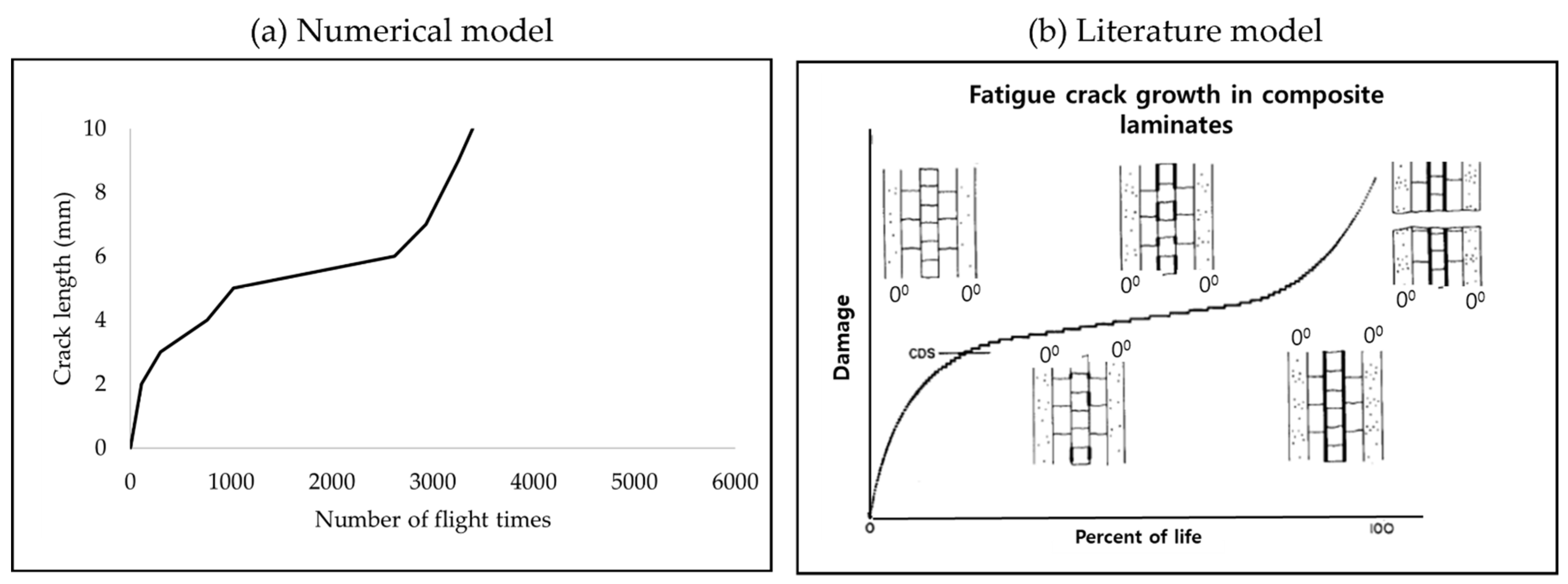
Figure 10a shows the fatigue cracks propagation plot measured as a function of the number of cycles for case simulation 5. The cracks started to propagate around 153 flight times, and increase rapidly until 1436 FHs. From the 14,336 cycles over 3692 FHs, the crack propagation occurred linearly with a low crack propagation rate, while after 4692 cycles, the crack propagation increased rapidly up to 4783 cycles until it reached the defined crack threshold length of 10 mm. The graph trend of the current model results was compared with the crack propagation curve in the literature [27] for a composite. It was found that compared with the composite crack propagation trend in the literature, the current numerical model showed a similar trend of crack propagation.

2.2. Sensitivity Analysis and Design of Experiments (DOE)

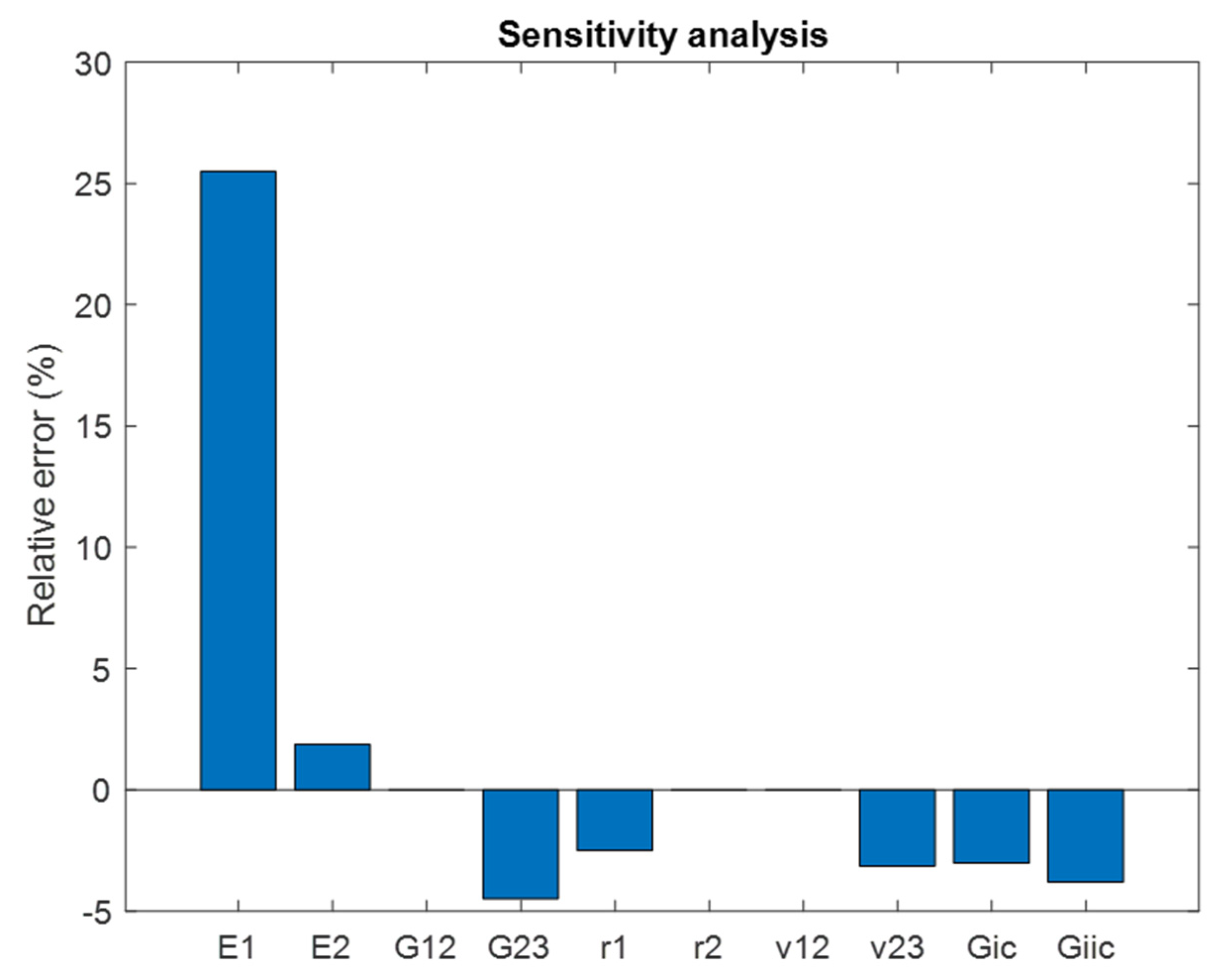
FRCPs subjected to cyclic loading are most likely to fail with fatigue delamination crack growth. Many factors can affect the fatigue delamination growth, such as the constituent material parameters, geometry, and environmental conditions. However, the most common practice is to check the effect of mechanical parameters on the fatigue delamination behavior of composite laminates. For this purpose, sensitivity analysis [28] was undertaken to assess the sensitivity of crack growth to uncertain mechanical parameters. Sensitivity analysis can be used as a tool to understand how uncertain inputs can affect a model’s performance. Sensitivity analysis is a systematic assessment method that is generally performed to assess the impact of individual input uncertain parameters on the model output response. It is an essential part of every risk assessment analysis that seeks to learn things such as how the model outputs change with the change in inputs and how it affects the model output decisions. The sensitivity analysis enhances the overall confidence in the risk assessment. Further, it improves the prediction of the model by studying the model response to the change in input variables and by analyzing the interaction between the variables. The knowledge of these sensitive parameters can help to better comprehend the fatigue delamination behavior and can pinpoint the direction of an optimal composite design. In this study, the effect of varying the mechanical properties was studied to examine the fatigue delamination behavior. Table 1 shows that a total of eight mechanical properties and two fatigue parameters were considered to examine the effect of fatigue delamination behavior. The parameters were varied by +2% of the mean value, and the model output fatigue delamination growth was computed. It was observed that E1 and G23 showed the most sensitive behavior compared with the other parameters. Figure 11 shows the relative error plot.
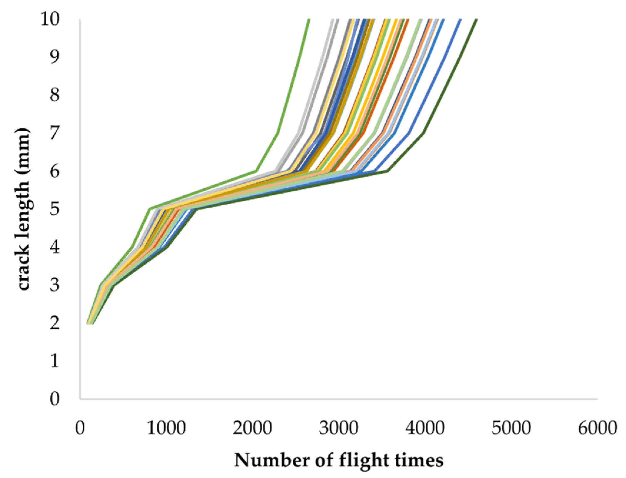
After pinpointing the most sensitive mechanical inputs, the design of experiments (DOE) was carried out by using Latin hypercube sampling (LHS) [29]. For the generation of DOE scenarios, input factors should be defined. In the case of fatigue crack propagation in the tail wing structure, two input factors (E1 and G23) were chosen. The error variation of +2% was kept for random sampling for the generation of thirty DOE samples, as shown in Table A1 of Appendix A. Figure 12 shows the fatigue crack propagation curves combined into a single plot. It was observed that for a crack delamination length threshold of 10 mm, the number of flight times range from approximately 2500 to 4600.

3. Risk Assessment and Inspection Interval Optimization

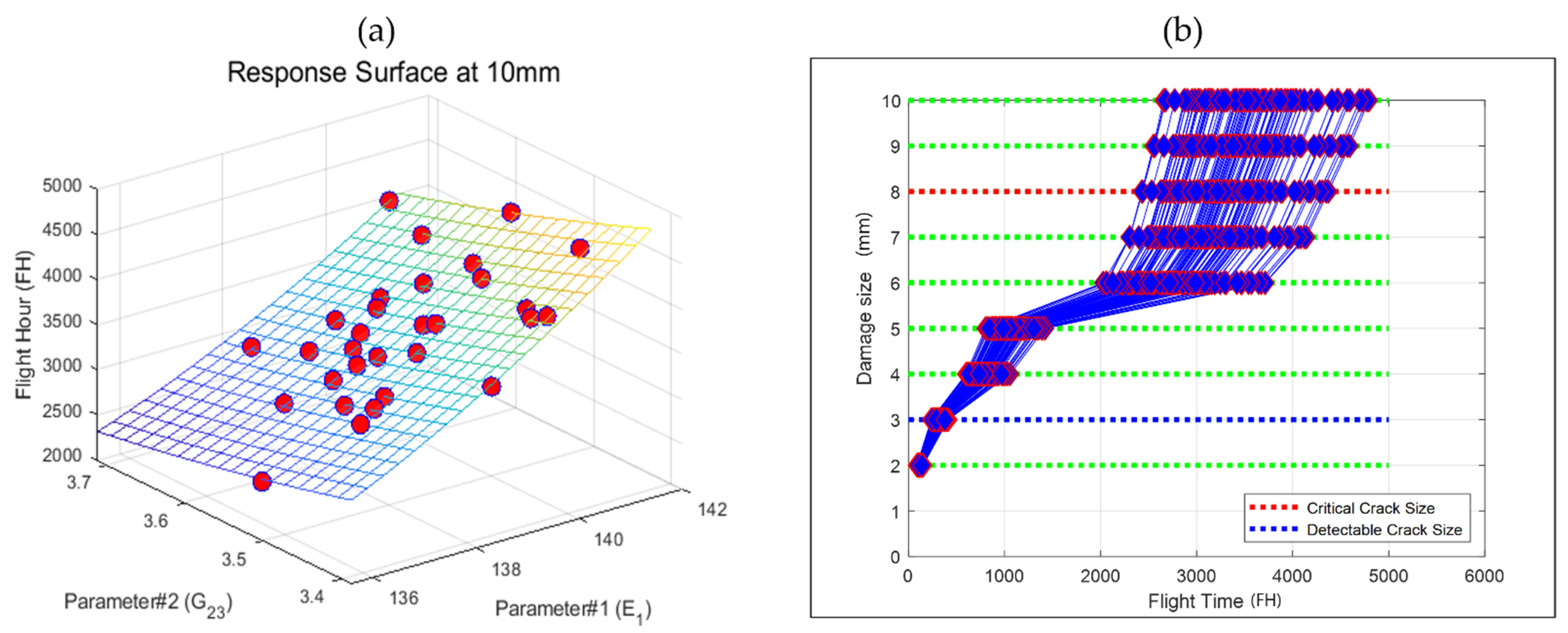
This section provides the results of the risk assessment and optimization of inspection interval for a composite aircraft tail wing structure. In the first stage of risk assessment, it is highly desirable to develop an efficient response surface that requires fewer FE executions. The composite crack propagation curve response surface was generated for both the sensitive parameters for the damage range of 2 to 10 mm. Thirty samples generated from the LHS were used for the generation of a total of nine response surfaces, as shown in Figure 13a. The average value of the mean square error (R2) of the nine response surfaces was 0.9987, with a minimum R2 value of 0.9962. It was confirmed that the response surface model satisfied the minimum standard value of R2 ≥ 0.990 set in this study. The present study dealt with the reliability evaluation of the structure using an efficient adaptive response-surface-based MCS technique. The analysis should consider all the uncertainties required for accurate damage growth modeling and risk assessment. For this purpose, damage growth simulation was performed using an MCS. The crack propagation curves using response surface modeling were accurately simulated compared with FE simulations, as represented in Figure 13b.
After the development of the response surface, we estimated the single flight probability of failure (SFPOF) assuming the structure was non-repairable. For the FRCPs, nondestructive inspection (NDI) was insufficient to detect the cracks that can propagate to complete failure of the structure. Therefore, it is essential to minimize the risk by computing the minimum inspection cycle. For this purpose, SFPOF was proposed in 1980 to assess the risk of aircraft failure [30]. It provides the probability of failure during one flight. To evaluate the risk, the criteria may vary depending on the operating environment conditions. The US Department of Defense proposed that a structural risk assessment should be performed on a component-by-component basis, and defined the limits on SFPOF of between 10−7 and 10−5 for each component. According to the suggested range, if SFPOF > 10−5, the component is unacceptable for operation. For 10−5 > SFPOF > 10−7, the structure requires repair and modification to ensure long-term operation. For SFPOF < 10−7, the structure is safe for long-term operation. In this study, SFPOF defined the amount of damage reached in the component with respect to the total number of simulations, as shown in Equation (5):
S F P O F = P ( a a c r i t i c a l ) = N c r i t i c a l N s i m u l a t i o n
where N c r i t i c a l is the number of simulations exceeding the critical damage size and N s i m u l a t i o n is the total number of simulations.
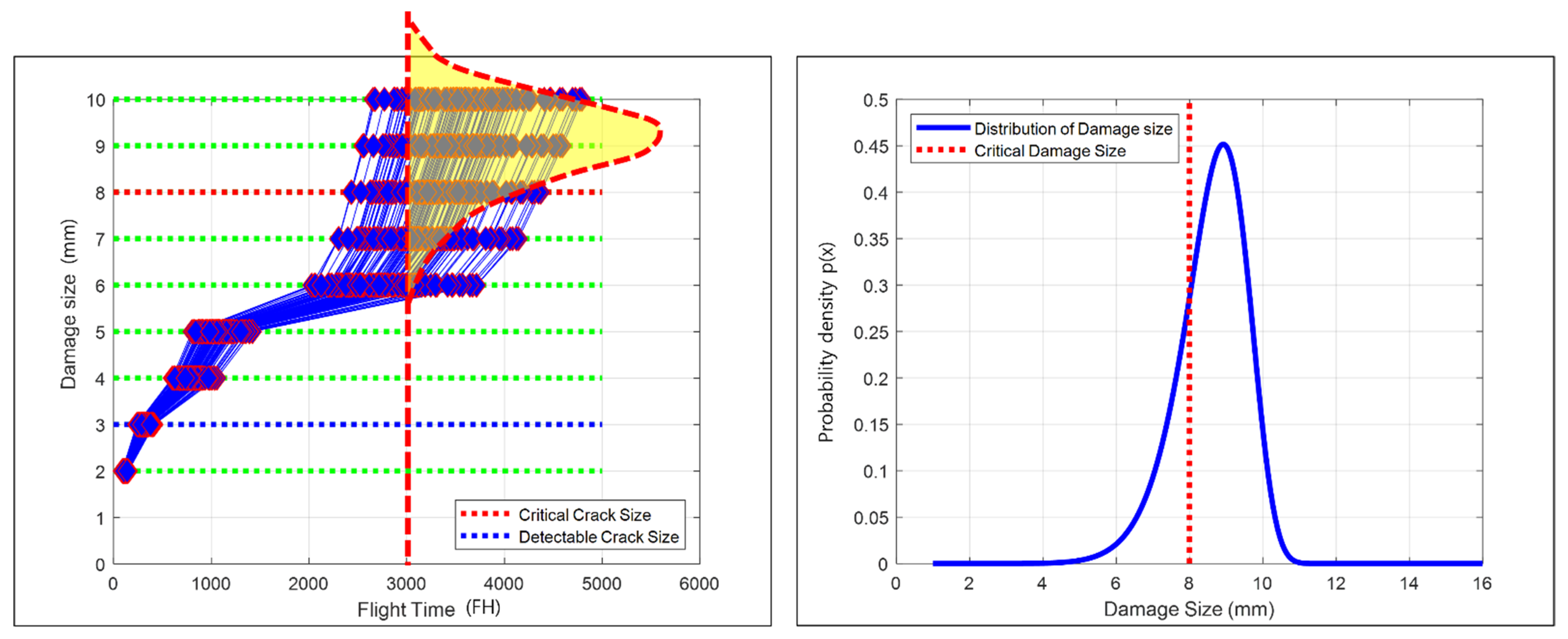
In this study, SFPOF was computed at 3000 FHs. At 3000 FHs, the damage distribution is calculated. The probability was computed for the scenario that the damage was greater than the critical crack size, which was 8 mm. Using the above process, the SFPOF was calculated for the total number of FH, as shown in Figure 14.
For a critical component, such as an aircraft tail wing, the common practice is to perform multiple inspections. The reason for repeated inspections is that the inspections are never perfect. There is always the possibility of misclassification. Therefore, repeated inspections are likely to reduce the inspection cost. For the determination of an optimal inspection plan, an optimal number of repeated inspections is needed. The time between repeated inspections can be computed using the following equation:
T r e p e a t = T d e s i g n T i n i t a l N I n s p e c t i o n + 1
where T i n i t a l is the initial inspection cycle, T d e s i g n is the operating life, and N I n s p e c t i o n is the number of repeated inspections. In this study, the service life of the tail wing structure considered was 3000 FHs, with the first inspection cycle at 200 FHs. Figure 15 shows the calculation of repeat inspection cycles with respect to the number of repeated inspections.
The criteria for determining the optimal inspection cycle in this study was based on the US Airforce standard of risk assessment matrix [31]. In the event of an accident, the severity level is divided into four levels based on the type of result, component damage, etc. The Risk Assessment Code, or Hazard Risk Index, is a risk level that is calculated by combining the severity and probability of occurrence, as shown in Table 3. A high risk constitutes the first−fifth level range. The serious risk of component failure falls in the sixth–ninth level range, the medium risk falls in the 10th–17th level, whereas the low risk is in the 18th−20th level range.
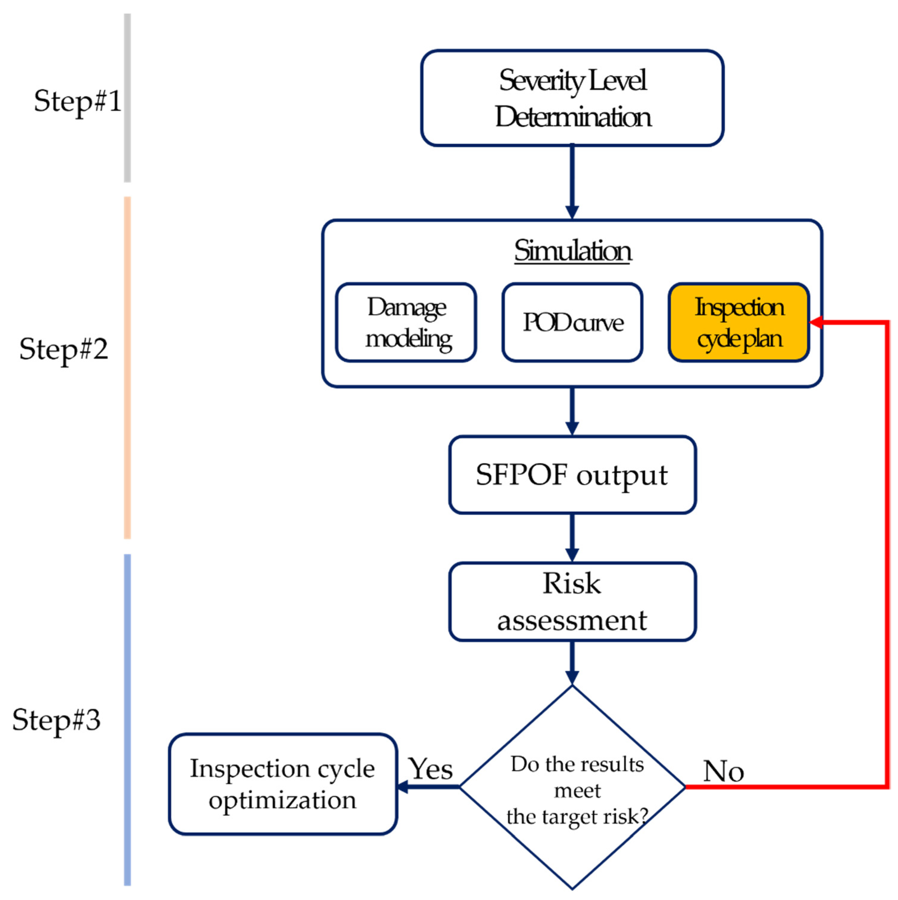
The overall process implemented in this study for determining the optimal inspection interval is divided into three steps, as shown in Figure 16:
  • Step #1. Determination of the severity category
In the event of an accident caused by a defined major failure mode, the severity level was determined after predicting the consequences.
  • Step #2. Calculation of the probability of failure (probability level)
The probability of failure was calculated by computing the SFPOF for each flight time.
  • Step #3. Risk assessment code
Steps #1 and #2 were combined to calculate the risk. If the calculated risk was less than the target level, step #2 was repeated after modifying the inspection cycle combination.
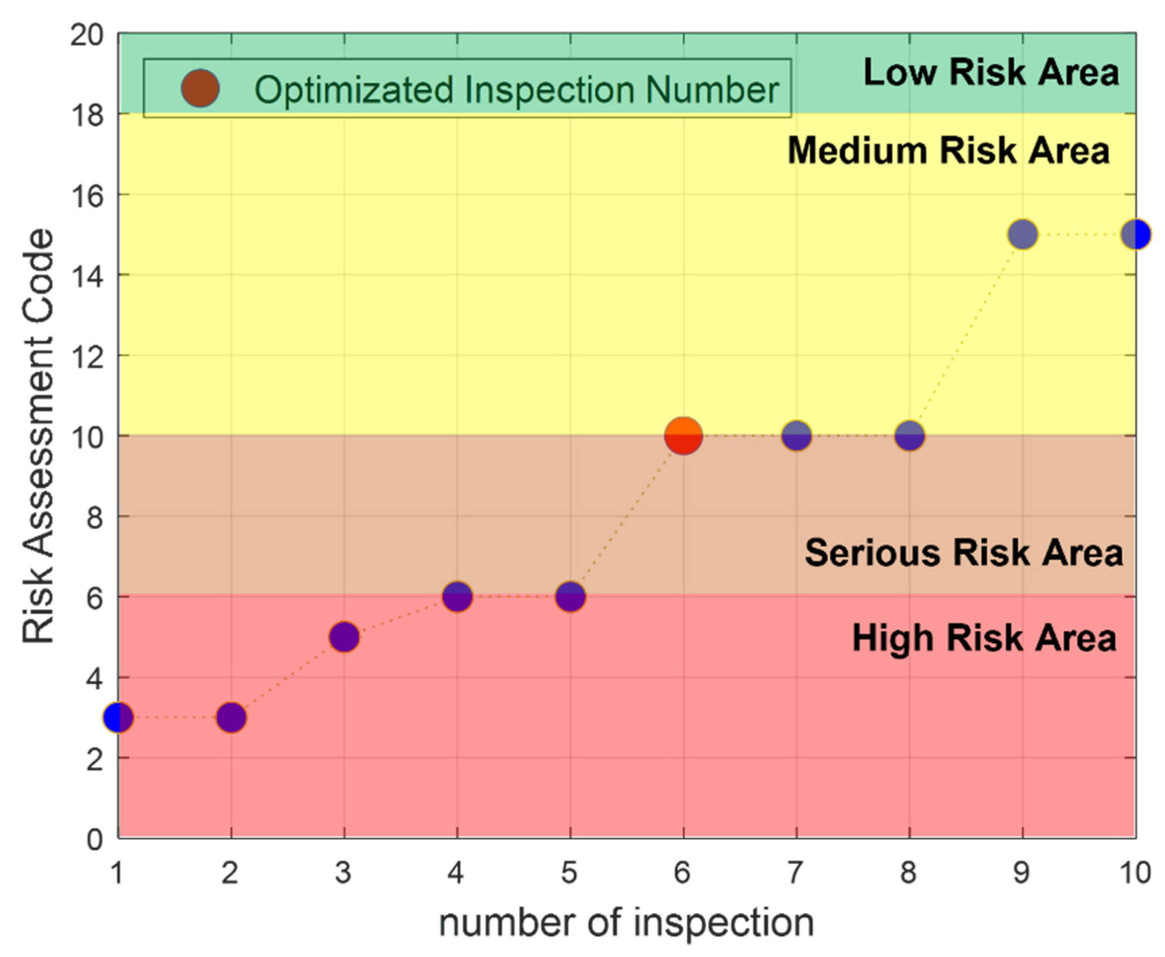
In the case example of an aircraft tail wing, the first step was computed by assuming the severity level to be critical. In the second step, the assumed operating life was 3000 flight times. After setting it equal to a critical value, the SFPOF was calculated for each FH until the end of the operating life, and the maximum SFPOF was set as the reference value. The RAC from the maximum probability of failure and severity level was calculated. If the target risk level was a medium risk: RAC 10−17, then the combination of the least number of repeated inspections among the combinations of inspection cycles that satisfied RAC 10−17 is selected. In this example, the optimal inspection cycle was calculated when the number of repeated inspections was six and fell within the medium risk level, as shown in Figure 17.

4. Conclusions

This study provided the risk assessment and optimization of the inspection interval of a composite aircraft tail wing structure. Composite structures are more prone to fatigue delamination damage and such damages can ultimately lead to the catastrophic failure of the complete aircraft composite structures, such as aircraft tail wings. Therefore, different aircraft maintenance strategies were proposed for the accurate prediction of the fatigue life of composite structures. However, the main limitation of the approaches available in the literature is the availability of real aircraft maintenance data to develop structural health monitoring approaches for the prediction of the fatigue life of the composite structures. The acquisition of the real damage data requires the embedding of additional sensors on the skin of aircraft structures, thus making the maintenance strategies more expensive. Therefore, to overcome the unavailability of real-life operating data, the study proposed the methodology of using the FEA-based model for the generation of fatigue damage growth curves and further implemented this approach for the risk assessment and optimization of the inspection interval of the KT-100 aircraft tail wing structure. The overall methodology of the proposed study and the concluding remarks are summarized as follows:
  • The FEA model based on VCCT and Paris’ law was implemented and compared with a real experimental curve. The fatigue damage model was extended to a full aircraft tail wing geometry and the fatigue delamination growth curve was computed.
  • A sensitivity analysis was undertaken to check the effect of mechanical parameters on the fatigue delamination growth curve; E1 and G23 were found to be the most sensitive parameters. The Latin hypercube sampling technique was used for the DOE data generation scenarios, where 30 scenarios were generated. Based on LHS, an efficient response surface was generated. A damage growth simulation was performed using an MCS.
  • In the end, a probabilistic risk analysis method was proposed based on the risk matrix of the US military specification, and the risk was analyzed based on the severity and frequency of structural failure. In future research, based on the process of determining the optimal inspection cycle, we will consider both the risk and the cost associated with the inspection.

Author Contributions

Conceptualization, H.S.K. (Heung Soo Kim) and J.-H.C.; methodology, S.K. and H.-S.K. (Hee-Seong Kim); software, S.K. and H.-S.K. (Hee-Seong Kim); formal analysis, S.K.; resources, H.S.K. (Heung Soo Kim) and J.-H.C.; writing—original draft preparation, S.K.; writing—review and editing, S.K., H.S.K. (Heung Soo Kim), J.-H.C. and H.-S.K. (Hee-Seong Kim); supervision, H.S.K. (Heung Soo Kim) and J.-H.C. All authors have read and agreed to the published version of the manuscript.

Funding

This research was supported under the project “Research and Development of Composite Internal Defect Risk Assessment Method” by the Aero Technology Research Institute and supported by the National Research Foundation of Korea (NRF) grant funded by the Korean government (MSIT) (no. 2020R1A2C1006613) and BK−21 four.

Conflicts of Interest

The authors declare that they have no conflict of interest.

Appendix A

Table A1. Latin hypercube sampling scenarios with E1 and G23 as input factors.
Scenario Number (#)E1 (MPa)G23 (MPa)Scenario #E1 (MPa)G23 (MPa)
1139.76159093.43831273916138.65395013.506192126
2141.39387023.5660542517138.79573793.587573885
3138.05811183.67890827218139.50757773.609318242
4139.17520973.53236861419137.73047323.486625586
5138.47008973.57575263120139.91773793.581053108
6135.56883853.50101731721137.40002673.51591805
7140.18250043.52391151822138.43670883.542198006
8139.31097883.60084175223139.67928563.406417978
9137.47270953.48255935624138.29260453.385928254
10138.92967983.62862172525137.82179863.558572124
11138.18949663.55195871326139.23904563.520360535
12140.91493633.44562838427137.16658893.57807592
13136.94616983.46524141128138.24488753.616984057
14140.41412093.55006546329139.6152283.423103266
15140.75744583.63856544430141.23579183.711960967

References

  1. Manco, P.; Caterino, M.; Macchiaroli, R.; Rinaldi, M.; Fera, M. Aircraft Maintenance: Structural Health Monitoring Influence on Costs and Practices; Wiley: Hoboken, NJ, USA, 2021; Volume 396, p. 2000302. [Google Scholar]
  2. Wild, G.; Pollock, L.; Abdelwahab, A.K.; Murray, J. The Need for Aerospace Structural Health Monitoring: A Review of Aircraft Fatigue Accidents. Int. J. Progn. Health Manag. 2021, 12. [Google Scholar] [CrossRef]
  3. Temucin, T.; Tuzkaya, G.; Vayvay, O. Aircraft Maintenance Routing Problem–A Literature Survey. Promet-Traffic Transp. 2021, 33, 491–503. [Google Scholar] [CrossRef]
  4. Healey, R.; Wang, J.; Chiu, W.K.; Chowdhury, N.M.; Baker, A.; Wallbrink, C. A Review on Aircraft Spectra Simplification Techniques for Composite Structures. Compos. Part C Open Access 2021, 5, 100131. [Google Scholar] [CrossRef]
  5. Das, M.; Sahu, S.; Parhi, D. Composite Materials and Their Damage Detection Using AI Techniques for Aerospace Application: A Brief Review. Mater. Today Proc. 2021, 44, 955–960. [Google Scholar] [CrossRef]
  6. Khalid, S.; Lee, J.; Kim, H.S. Series Solution-Based Approach for the Interlaminar Stress Analysis of Smart Composites under Thermo-Electro-Mechanical Loading. Mathematics 2022, 10, 268. [Google Scholar] [CrossRef]
  7. Khalid, S.; Kim, H.S. Recent Studies on Stress Function-Based Approaches for the Free Edge Stress Analysis of Smart Composite Laminates: A Brief Review. Multiscale Sci. Eng. 2022, 4, 73–78. [Google Scholar] [CrossRef]
  8. Khalid, S.; Kim, H.S. Progressive Damage Modeling of Inter and Intra Laminar Damages in Open Hole Tensile Composite Laminates. JCOSEIK 2019, 32, 233–240. [Google Scholar] [CrossRef]
  9. Teimouri, F.; Heidari-Rarani, M.; Aboutalebi, F.H. An XFEM-VCCT Coupled Approach for Modeling Mode I Fatigue Delamination in Composite Laminates under High Cycle Loading. Eng. Fract. Mech. 2021, 249, 107760. [Google Scholar] [CrossRef]
  10. Ahmadi, A.; Söderholm, P.; Kumar, U. On Aircraft Scheduled Maintenance Program Development. J. Qual. Maint. Eng. 2010, 3, 229–255. [Google Scholar] [CrossRef]
  11. Jing, C.; Dingqiang, D. Inspection Interval Optimization for Aircraft Composite Structures with Dent and Delamination Damage. J. Syst. Eng. Electron. 2021, 32, 252–260. [Google Scholar] [CrossRef]
  12. Ushakov, A.; Stewart, A.; Mishulin, I.; Pankov, A. Probabilistic Design of Damage Tolerant Composite Aircraft Structures; Federal Aviation Administration, Office of Aviation Research: Washington, DC, USA, 2002. [Google Scholar]
  13. Kan, H.-P.; Kane, D. Probabilistic Certification of Integrally Bonded Composite Structures—An Assessment; American Institute of Aeronautics and Astronautics: Denver, CO, USA, 2002; p. 1388. [Google Scholar]
  14. Lin, K.Y.; Styuart, A.V. Probabilistic Approach to Damage Tolerance Design of Aircraft Composite Structures. J. Aircr. 2007, 44, 1309–1317. [Google Scholar] [CrossRef] [Green Version]
  15. Dinis, D.; Barbosa-Póvoa, A.; Teixeira, Â.P. Valuing Data in Aircraft Maintenance through Big Data Analytics: A Probabilistic Approach for Capacity Planning Using Bayesian Networks. Comput. Ind. Eng. 2019, 128, 920–936. [Google Scholar] [CrossRef]
  16. Giannella, V. Uncertainty Quantification in Fatigue Crack-Growth Predictions. Int. J. Fract. 2022, 235, 179–195. [Google Scholar] [CrossRef]
  17. Zhu, M.; Gorbatikh, L.; Lomov, S.V. An Incremental-Onset Model for Fatigue Delamination Propagation in Composite Laminates. Compos. Sci. Technol. 2020, 200, 108394. [Google Scholar] [CrossRef]
  18. Zhou, S.; Li, Y.; Fu, K.; Wu, X. Progressive Fatigue Damage Modelling of Fibre-Reinforced Composite Based on Fatigue Master Curves. Thin-Walled Struct. 2021, 158, 107173. [Google Scholar] [CrossRef]
  19. Dávila, C. From SN to the Paris Law with a New Mixed-Mode Cohesive Fatigue Model for Delamination in Composites. Theor. Appl. Fract. Mech. 2020, 106, 102499. [Google Scholar] [CrossRef]
  20. Raimondo, A.; Doesburg, S.; Bisagni, C. Numerical Study of Quasi-Static and Fatigue Delamination Growth in a Post-Buckled Composite Stiffened Panel. Compos. Part B Eng. 2020, 182, 107589. [Google Scholar] [CrossRef]
  21. Abaqus Analysis User’s Manual-Abaqus Version 6.14; Simulia: Johnston, RI, USA.
  22. Rozylo, P. Experimental-Numerical Study into the Stability and Failure of Compressed Thin-Walled Composite Profiles Using Progressive Failure Analysis and Cohesive Zone Model. Compos. Struct. 2021, 257, 113303. [Google Scholar] [CrossRef]
  23. Chen, S.; Mitsume, N.; Bui, T.Q.; Gao, W.; Yamada, T.; Zang, M.; Yoshimura, S. Development of Two Intrinsic Cohesive Zone Models for Progressive Interfacial Cracking of Laminated Composites with Matching and Non-Matching Cohesive Elements. Compos. Struct. 2019, 229, 111406. [Google Scholar] [CrossRef]
  24. Liang, Y.-J.; Dávila, C.G.; Iarve, E.V. A Reduced-Input Cohesive Zone Model with Regularized Extended Finite Element Method for Fatigue Analysis of Laminated Composites in Abaqus. Compos. Struct. 2021, 275, 114494. [Google Scholar] [CrossRef]
  25. Heidari-Rarani, M.; Sayedain, M. Finite Element Modeling Strategies for 2D and 3D Delamination Propagation in Composite DCB Specimens Using VCCT, CZM and XFEM Approaches. Theor. Appl. Fract. Mech. 2019, 103, 102246. [Google Scholar] [CrossRef]
  26. NASA/TM-2008-215123; An Approach to Assess Delamination Propagation Simulation Capabilities in Commercial Finite Element Codes. National Aeronautics and Space Administration: Hampton, VA, USA, 2008.
  27. Munagala, P. Fatigue Life Prediction of GFRP Composite Material at Coupon and Component Level. Master’s Thesis, West Virginia University Libraries, Morgantown, WV, USA, 2005. [Google Scholar]
  28. Chamis, C.C. Probabilistic Simulation of Multi-Scale Composite Behavior. Theor. Appl. Fract. Mech. 2004, 41, 51–61. [Google Scholar] [CrossRef]
  29. Matala, A. Sample Size Requirement for Monte Carlo Simulations Using Latin Hypercube Sampling; Helsinki University of Technology: Espoo, Finland, 2008; Volume 25. [Google Scholar]
  30. Domyancic, L.; McFarland, J.M.; Cardinal, J.W. Review of Methods for Calculating Single Flight Probability of Failure. In Proceedings of the AIAA Scitech 2021 Forum, Virtual Event, 11–15 & 19–21 January 2021; p. 1490. [Google Scholar]
  31. Altowairqi, M.M. Evaluation of RSAF Airworthiness and Applicability; Air Force Institute of Technology Wright-Patterson: Wright-Patterson AFB, OH, USA, 2018. [Google Scholar]
Figure 1. Schematic of the proposed FE-based inspection interval optimization approach.
Mathematics 10 03836 g001
Figure 2. DCB specimen geometry with initial delamination.
Mathematics 10 03836 g002
Figure 3. Load vs. displacement curve of the DCB specimen [26].
Mathematics 10 03836 g003
Figure 4. Comparison of the numerical and experimental fatigue delamination propagation curve [23,26].
Mathematics 10 03836 g004
Figure 5. Skin-debonding damage in aircraft tail wing structure.
Mathematics 10 03836 g005
Figure 6. (a) Geometry of a tail wing with initial delamination and (b) the mesh configuration of the model.
Mathematics 10 03836 g006
Figure 7. Flight loading spectrum for each fatigue cycle.
Mathematics 10 03836 g007
Figure 8. BDSTAT plot representing the cracked region between the upper skin and the middle.
Mathematics 10 03836 g008
Figure 9. Crack propagation plot for the different applied loading conditions.
Mathematics 10 03836 g009
Figure 10. (a) Crack propagation plot of the current numerical model and (b) a comparison with the literature trend of the composite fatigue crack propagation curve [27].
Mathematics 10 03836 g010
Figure 11. Sensitivity analysis plot representing the relative error of each parameter with respect to the exact simulation parameters fatigue behavior.
Mathematics 10 03836 g011
Figure 12. Fatigue delamination behavior of DOE data generation scenarios.
Mathematics 10 03836 g012
Figure 13. (a) Response surface generation using Latin hypercube sampling design and (b) the simulation response surface based on FEA simulations.
Mathematics 10 03836 g013
Figure 14. Single flight probability of failure calculation at 3000 FHs.
Mathematics 10 03836 g014
Figure 15. Number of repeated inspections with respect to the number of inspection plans.
Mathematics 10 03836 g015
Figure 16. Process of determining the optimal inspection cycle.
Mathematics 10 03836 g016
Figure 17. Selection of optimized inspection from the RAC-vs.-severity-level curve.
Mathematics 10 03836 g017
Table 1. Material properties and fatigue parameters of T300/1076 graphite epoxy.
ParametersNotationsValue
Elastic modulus in direction 1E1139,400 MPa
Elastic modulus in directions 2 and 3 E2 = E310,160 MPa
Shear modulus in directions 12 and 13G12 = G134600 MPa
Shear modulus in direction 23G233540 MPa
Poisson’s ratio in direction 12 and 13ν120.3
Poisson’s ratio in direction 23ν230.436
Fracture toughness in direction 1GIC0.17 kJ/m2
Fracture toughness in direction 2GiiC0.49 kJ/m2
Lower fatigue crack growth thresholdr10.67
Upper fatigue crack growth thresholdr20.067
Table 2. Case simulation scenarios.
Case SimulationApplied Shear Force
Magnitude
Load Increase (%)
Case 11.849 KN-
Case 22.2 KN18.9%
Case 32.6 KN40.6%
Case 43.0 KN62.2%
Case 53.7 KN100%
Table 3. US Airforce airworthiness risk assessment matrix [31].
USAF Airworthiness Risk Assessment MatrixSeverity Category
Probability
Level
Probability per FH or SortieFreq per 100 K FH or 100 K SortiesCatastrophic
(1)
Critical
(2)
Marginal
(3)
Negligible
(4)
Frequent
(A)
10 3  Prob 100 F r e q 13713
Probable
(B)
10 4 P r o b < 10 3 10 F r e q < 100 25916
Occasional
(C)
10 5 P r o b < 10 4 1 F r e q < 10 461118
Remote
(D)
10 6 P r o b < 10 5 0.1 F r e q < 1 8101419
Improbable
(E)
0 < P r o b < 10 6 0 F r e q < 0.1 12151720
Eliminated
(F)
Prob = 0Freq = 0Eliminated
Publisher’s Note: MDPI stays neutral with regard to jurisdictional claims in published maps and institutional affiliations.