


A Novel Universal Torque Control of Switched Reluctance Motors for Electric Vehicles

 ,
,  , ,
, ,  and
and
Abstract
:1. Introduction
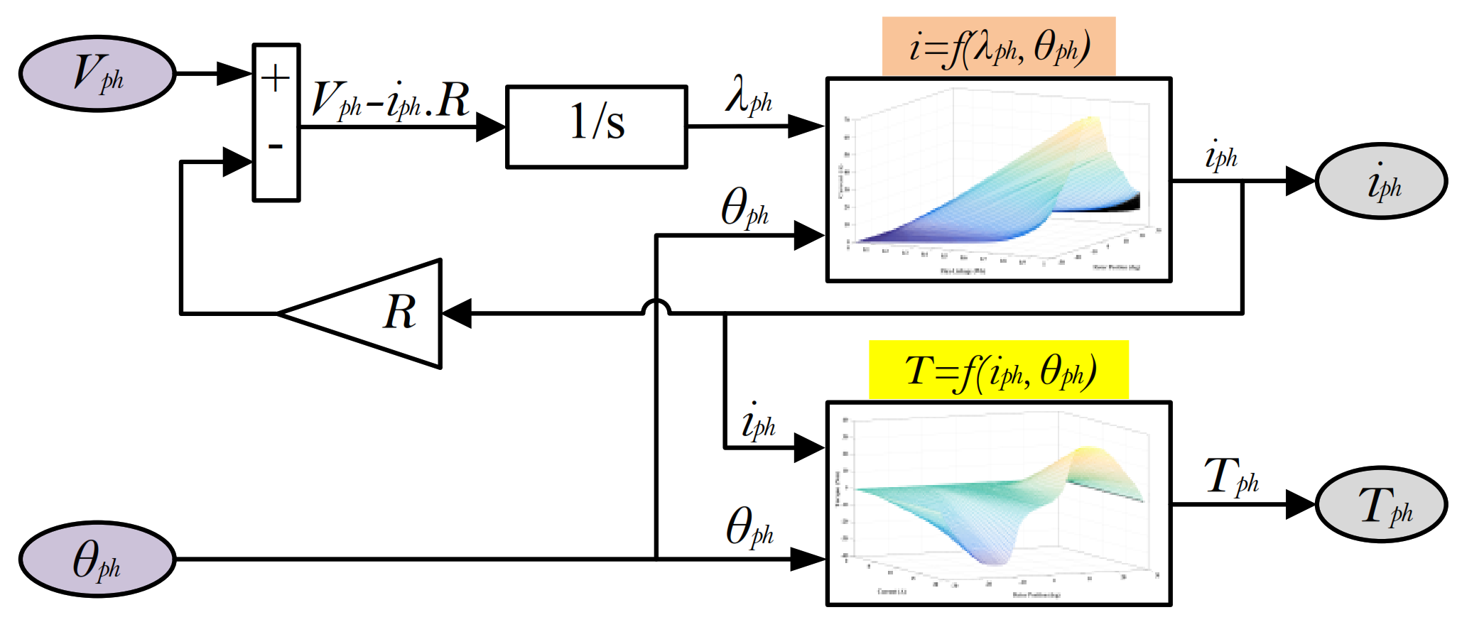
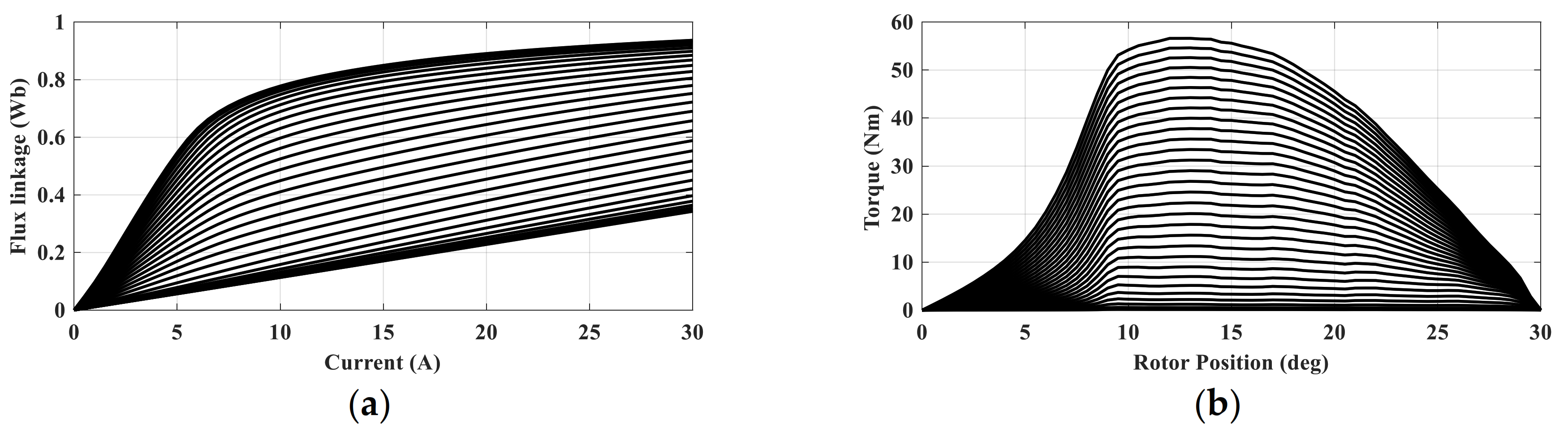
2. Modeling of SRM
2.1. Machine Model
2.2. Performance Indices
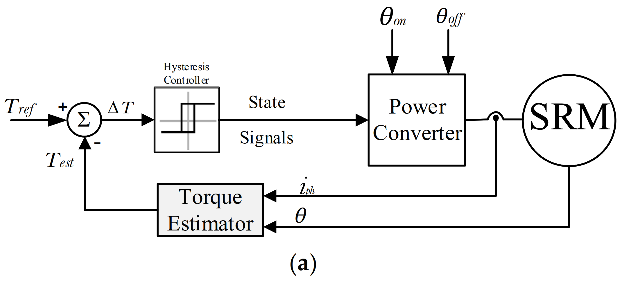
3. The Conventional ATC and DITC Techniques for SRMs
3.1. The Conventional ATC Technique
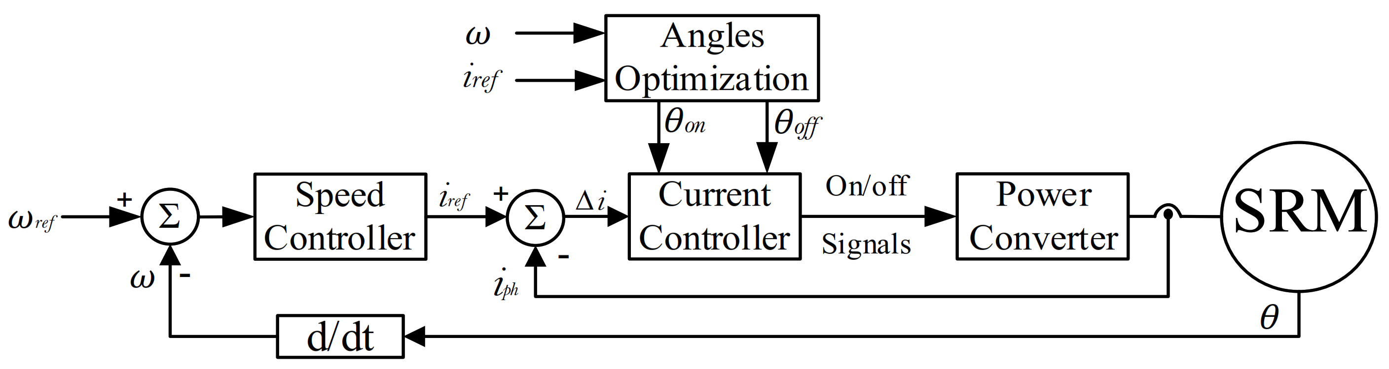
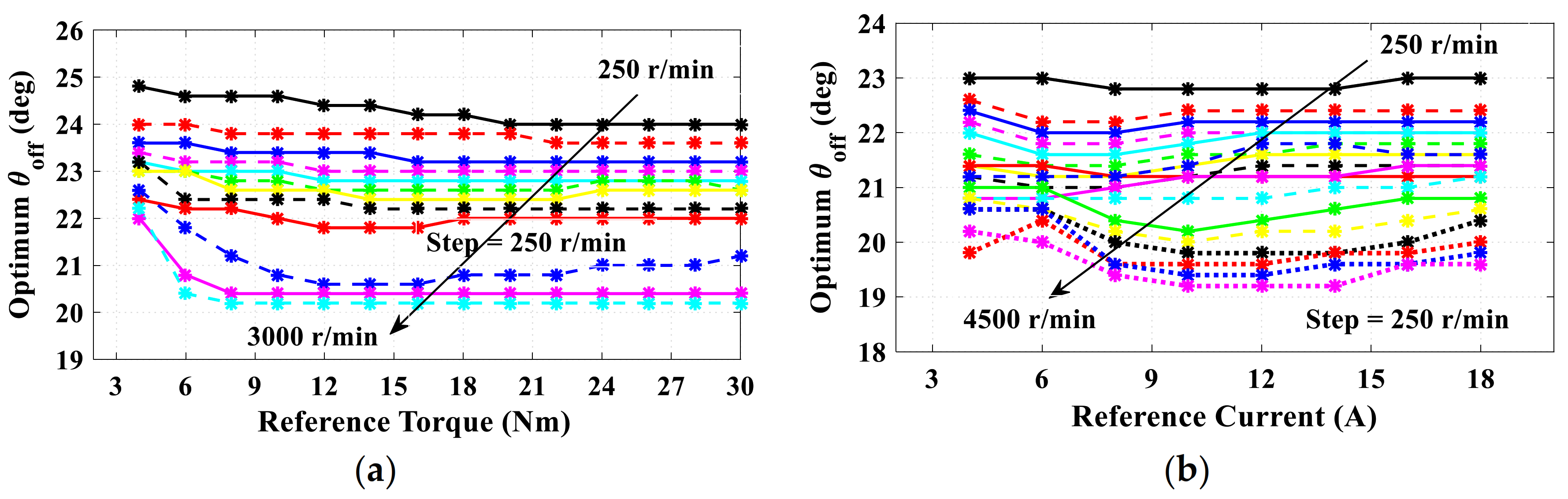
Optimization of Firing Angles (θon and θoff) for ATC Technique
3.2. The Conventional DITC Technique
Optimization of Firing Angles (θon and θoff) for DITC Technique
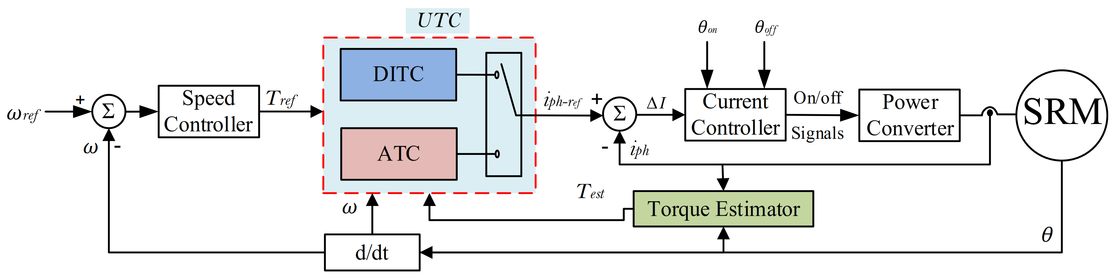
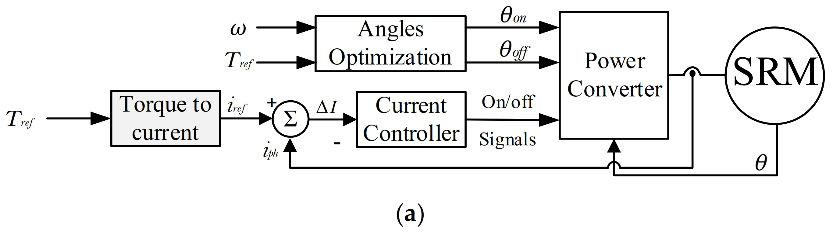
4. The Proposed Universal Torque Control (UTC) of SRM for EVs
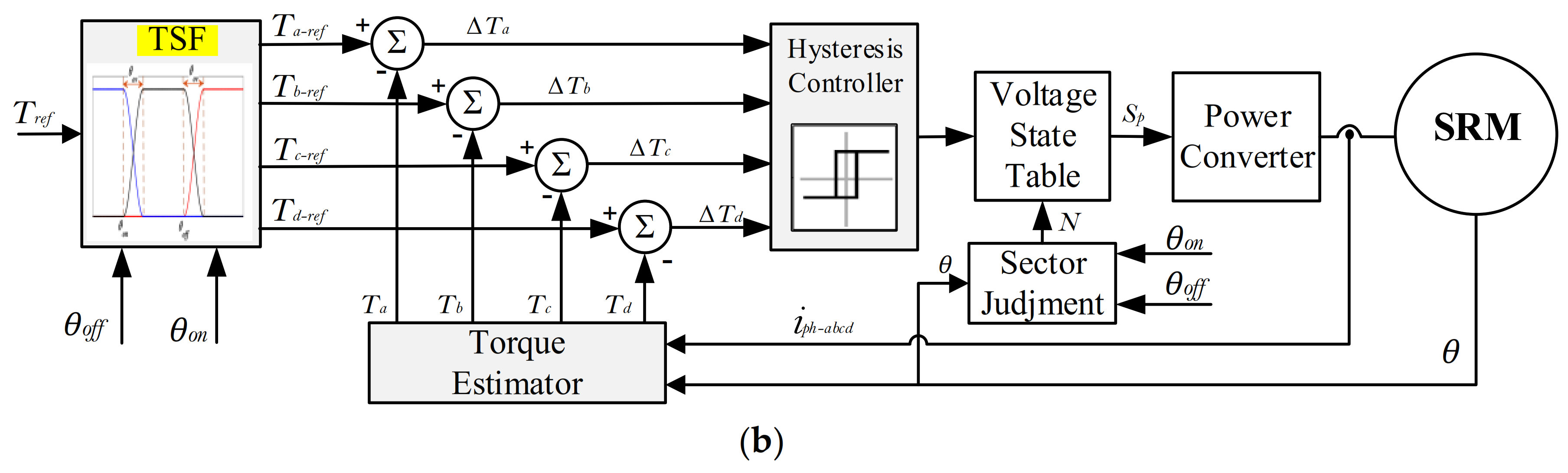
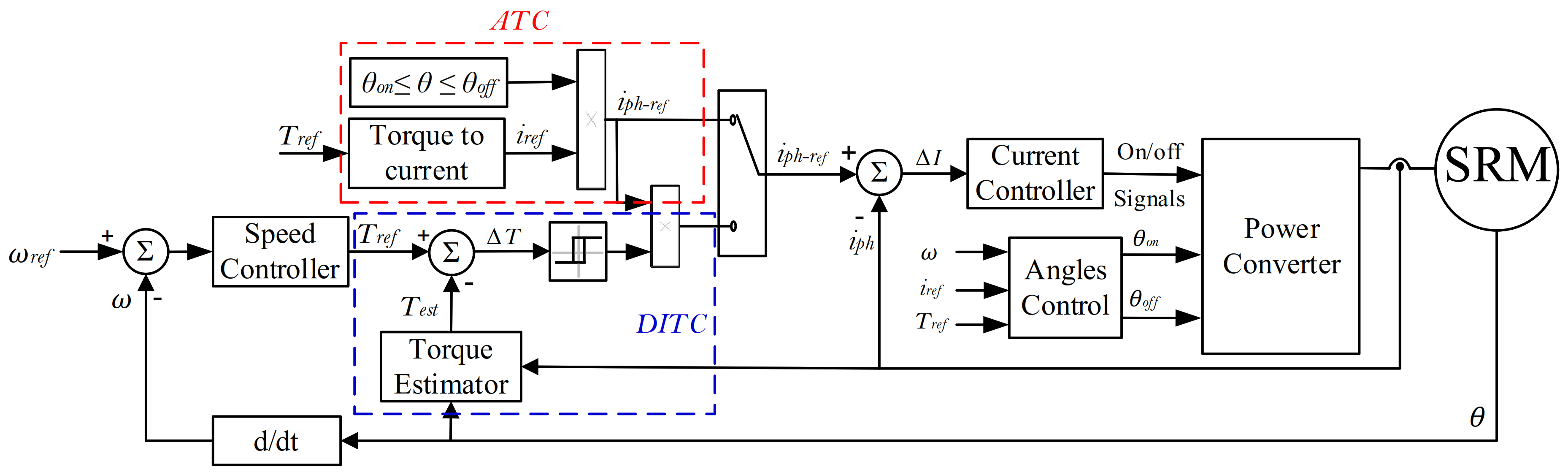
4.1. The Proposed DITC Technique
4.2. The Proposed ATC Technique
4.3. The Final Intergrated UTC
Smooth Transition Control
5. Simulation Results and Discussion
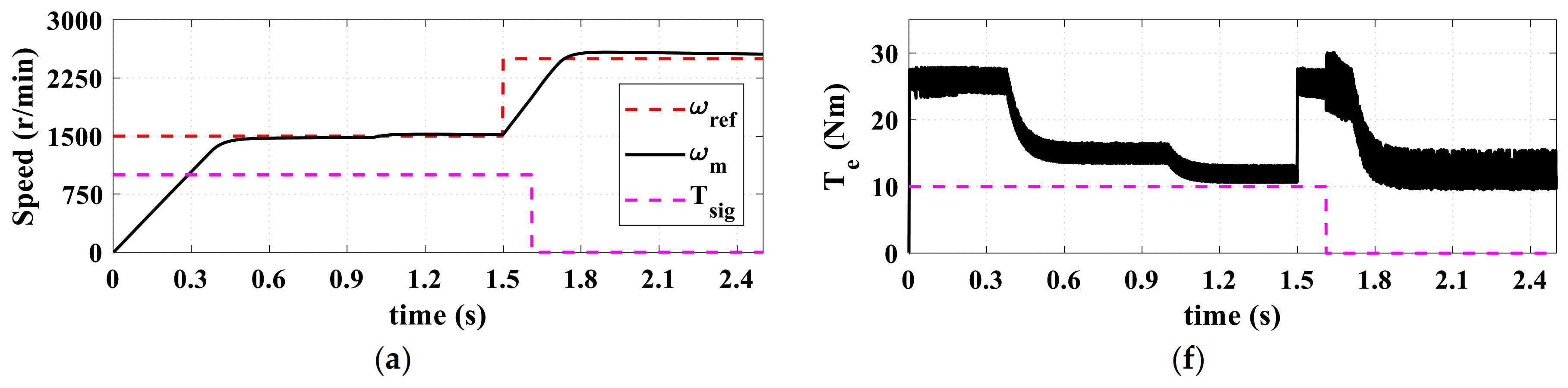
5.1. Sudden Change in Reference Speed and Load Torque
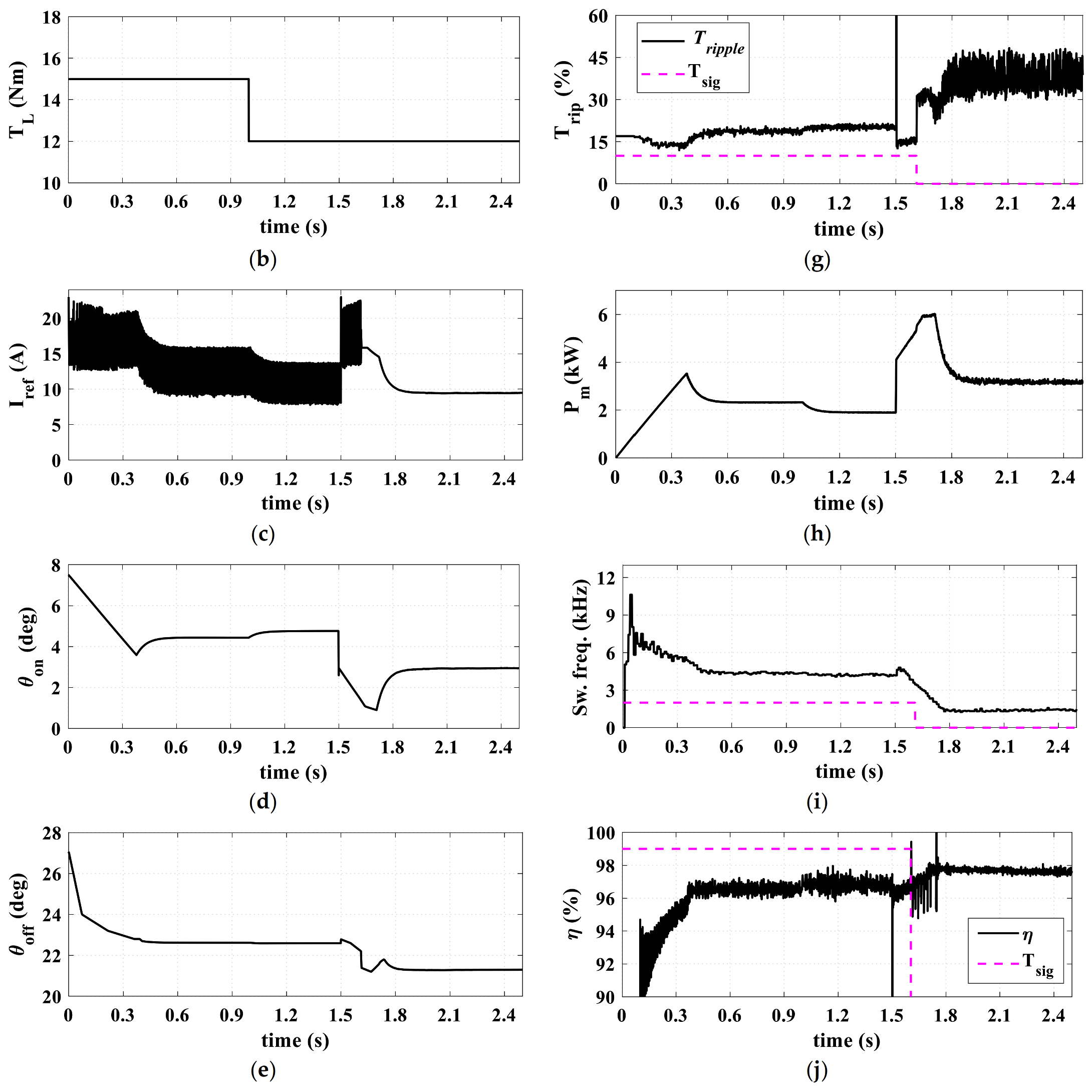
5.2. Acceleration with Electric Vehicle Loading
5.3. Acceleration and Deceleration with Electric Vehicle Loading
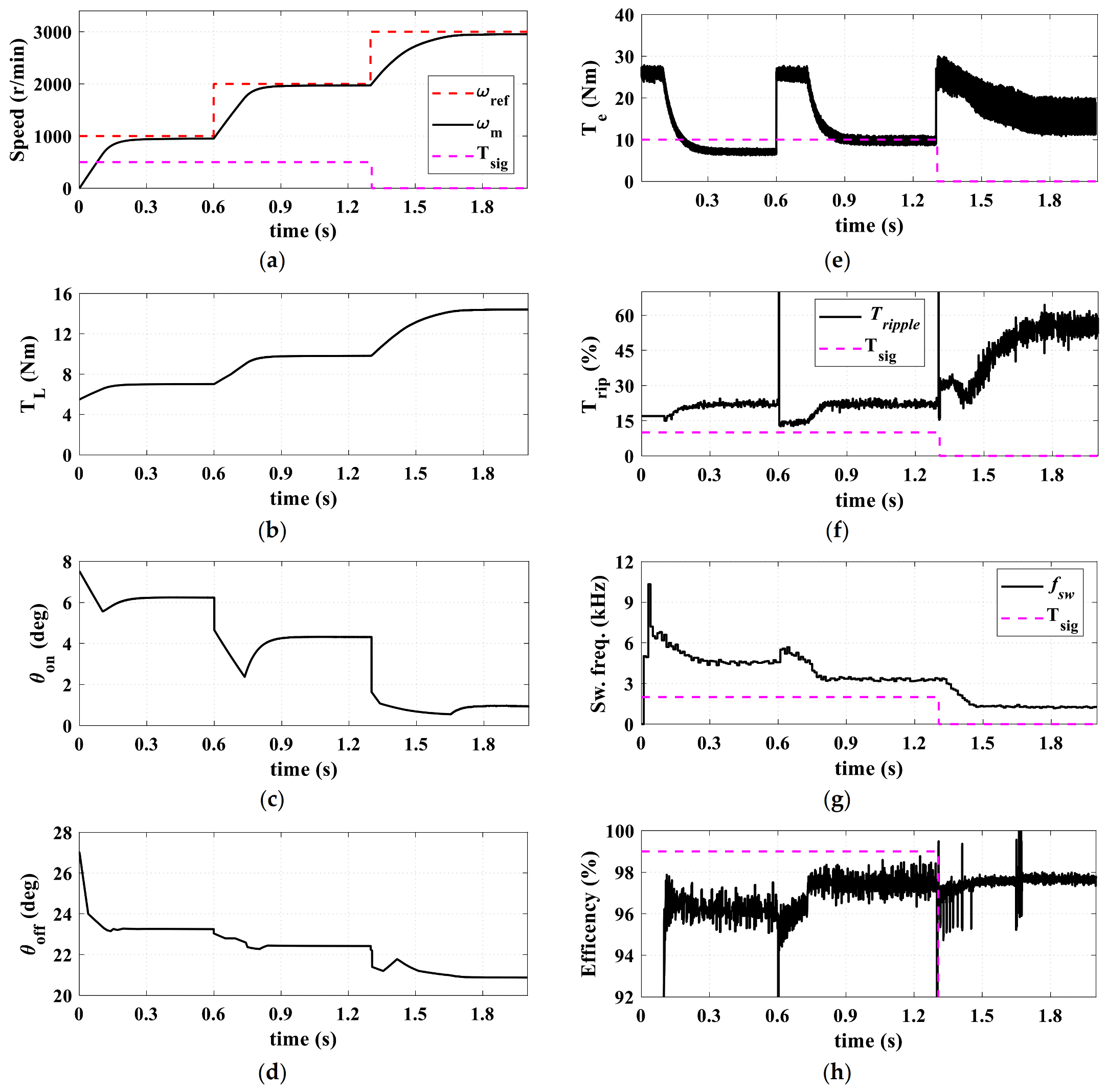
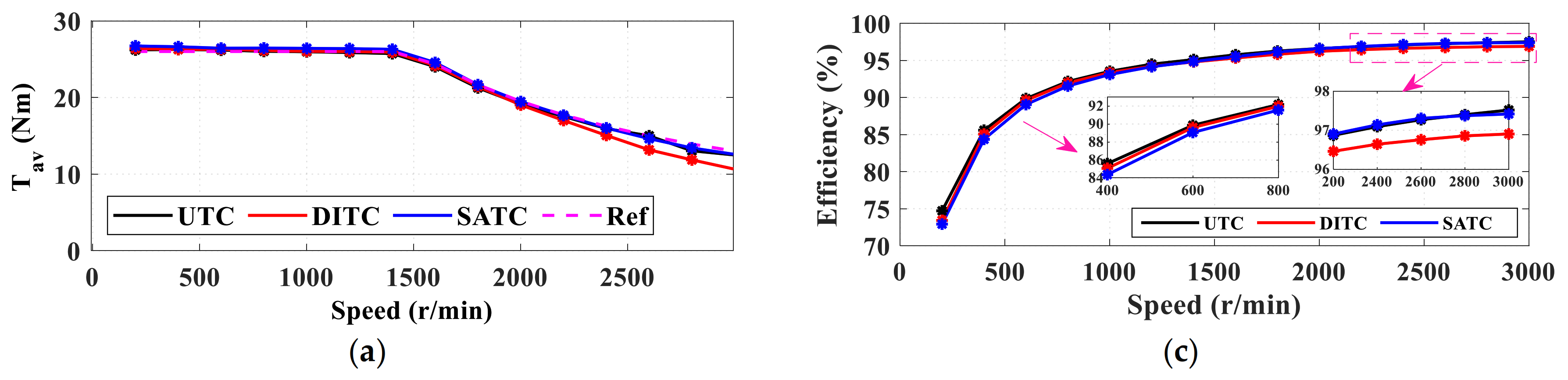
6. Comparative Analysis
6.1. Under Dynamic Loading Conditions
6.2. Under EV Loading Profile
6.3. Under Full Load Conditions
6.4. Summary
7. Conclusions
Author Contributions
Funding
Conflicts of Interest
References
- Lan, Y.; Benomar, Y.; Deepak, K.; Aksoz, A.; El Baghdadi, M.; Bostanci, E.; Hegazy, O. Switched Reluctance Motors and Drive Systems for Electric Vehicle Powertrains: State of the Art Analysis and Future Trends. Energies 2021, 14, 2079. [Google Scholar] [CrossRef]
- Yueying, Z.; Chuantian, Y.; Yuan, Y.; Weiyan, W.; Chengwen, Z. Design and optimisation of an In-wheel switched reluctance motor for electric vehicles. IET Intell. Transp. Syst. 2019, 13, 175–182. [Google Scholar] [CrossRef]
- Nam, K.H. AC Motor Control and Electrical Vehicle Applications; CRC Press: Boca Raton, FL, USA, 2019. [Google Scholar]
- Bostanci, E.; Moallem, M.; Parsapour, A.; Fahimi, B. Opportunities and Challenges of Switched Reluctance Motor Drives for Electric Propulsion: A Comparative Study. IEEE Trans. Transp. Electrif. 2017, 3, 58–75. [Google Scholar] [CrossRef]
- Zhu, J.; Cheng, K.W.E.; Xue, X. Design and Analysis of a New Enhanced Torque Hybrid Switched Reluctance Motor. IEEE Trans. Energy Convers. 2018, 33, 1965–1977. [Google Scholar] [CrossRef]
- Bramerdorfer, G.; Tapia, J.A.; Pyrhonen, J.J.; Cavagnino, A. Modern Electrical Machine Design Optimization: Techniques, Trends, and Best Practices. IEEE Trans. Ind. Electron. 2018, 65, 7672–7684. [Google Scholar] [CrossRef]
- Chen, H.; Yan, W.; Gu, J.J.; Sun, M. Multiobjective Optimization Design of a Switched Reluctance Motor for Low-Speed Electric Vehicles with a Taguchi-CSO Algorithm. IEEE/ASME Trans. Mechatron. 2018, 23, 1762–1774. [Google Scholar] [CrossRef]
- Mousavi-Aghdam, S.R.; Feyzi, M.R.; Bianchi, N.; Morandin, M. Design and Analysis of a Novel High-Torque Stator-Segmented SRM. IEEE Trans. Ind. Electron. 2016, 63, 1458–1466. [Google Scholar] [CrossRef]
- Ding, W.; Yang, S.; Hu, Y.; Li, S.; Wang, T.; Yin, Z. Design Consideration and Evaluation of a 12/8 High-Torque Modular-Stator Hybrid Excitation Switched Reluctance Machine for EV Applications. IEEE Trans. Ind. Electron. 2017, 64, 9221–9232. [Google Scholar] [CrossRef]
- Dmitrievskii, V.; Prakht, V.; Kazakbaev, V. Novel rotor design for high-speed flux reversal motor. Energy Rep. 2020, 6, 1544–1549. [Google Scholar] [CrossRef]
- Fang, G.; Pinarello Scalcon, F.; Xiao, D.; Vieira, R.; Grundling, H.; Emadi, A. Advanced Control of Switched Reluctance Motors (SRMs): A Review on Current Regulation, Torque Control and Vibration Suppression. IEEE Open J. Ind. Electron. Soc. 2021, 2, 280–301. [Google Scholar] [CrossRef]
- Al-Amyal, F.; Számel, L. Analytical Approach for the Turn-Off Angle in Switched Reluctance Motors. Lect. Notes Networks Syst. 2022, 217, 685–696. [Google Scholar] [CrossRef]
- Al-Amyal, F.; Hamouda, M.; Számel, L. Torque Quality Improvement of Switched Reluctance Motor Using Ant Colony Algorithm. Acta Polytech. Hung. 2021, 18, 129–150. [Google Scholar] [CrossRef]
- Shahabi, A.; Rashidi, A.; Afshoon, M.; Saghaıan Nejad, S.M. Commutation angles adjustment in SRM drives to reduce torque ripple below the motor base speed. Turkısh J. Electr. Eng. Comput. Sci. 2016, 24, 669–682. [Google Scholar] [CrossRef]
- Hamouda, M.; Számel, L. Optimum Control Parameters of Switched Reluctance Motor for Torque Production Improvement over the Entire Speed Range. Acta Polytech. Hung. 2019, 16, 3. [Google Scholar] [CrossRef]
- Al-Amyal, F.; Hamouda, M.; Számel, L. Performance improvement based on adaptive commutation strategy for switched reluctance motors using direct torque control. Alex. Eng. J. 2022, 61, 9219–9233. [Google Scholar] [CrossRef]
- Li, H.; Bilgin, B.; Emadi, A. An Improved Torque Sharing Function for Torque Ripple Reduction in Switched Reluctance Machines. IEEE Trans. Power Electron. 2019, 34, 1635–1644. [Google Scholar] [CrossRef]
- Li, C.; Zhang, C.; Liu, J.; Bian, D. A High-Performance Indirect Torque Control Strategy for Switched Reluctance Motor Drives. Math. Probl. Eng. 2021, 2021, 1–15. [Google Scholar] [CrossRef]
- Liu, J.; Wang, L.; Yi, L.; Zhu, G.; Yin, X. Optimization of SRM Direct Instantaneous Torque Control Strategy based on Improved Firefly Algorithm. In Proceedings of the 2019 3rd IEEE Conference on Energy Internet and Energy System Integration: Ubiquitous Energy Network Connecting Everything, EI2 2019, Changsha, China, 8–10 November 2019; pp. 364–368. [Google Scholar] [CrossRef]
- Wang, S.; Hu, Z.; Cui, X. Research on Novel Direct Instantaneous Torque Control Strategy for Switched Reluctance Motor. IEEE Access 2020, 8, 66910–66916. [Google Scholar] [CrossRef]
- Pillai, A.; Anuradha, S.; Gangadharan, K.V.; Umesht, P.; Bhaktha, S. Modeling and Analysis of Average Torque Control Strategy on Switched Reluctance Motor for E-mobility. In Proceedings of the CONECCT 2021 7th IEEE International Conference on Electronics, Computing and Communication Technologies, Bengaluru, India, 9–11 July 2021. [Google Scholar] [CrossRef]
- Fan, J.; Lee, Y. A Novel Average Torque Control of Switched Reluctance Motor Based on Flux-Current Locus Control. Can. J. Electr. Comput. Eng. 2020, 43, 273–281. [Google Scholar] [CrossRef]
- Usman Jamil, M.; Kongprawechnon, W.; Chayopitak, N. Average Torque Control of a Switched Reluctance Motor Drive for Light Electric Vehicle Applications. IFAC-PapersOnLine 2017, 50, 11535–11540. [Google Scholar] [CrossRef]
- Hamouda, M.; Abdel Menaem, A.; Rezk, H.; Ibrahim, M.N.; Számel, L. Numerical Estimation of Switched Reluctance Motor Excitation Parameters Based on a Simplified Structure Average Torque Control Strategy for Electric Vehicles. Mathematics 2020, 8, 1213. [Google Scholar] [CrossRef]
- Fang, G.; Bauman, J. Optimized switching angle-based torque control of switched reluctance machines for electric vehicles. In Proceedings of the 2020 IEEE Transportation Electrification Conference and Expo, ITEC 2020, Chicago, IL, USA, 22–26 June 2020; pp. 186–191. [Google Scholar] [CrossRef]
- Hamouda, M.; Szamel, L. Reduced Torque Ripple based on a Simplified Structure Average Torque Control of Switched Reluctance Motor for Electric Vehicles. In Proceedings of the 2018 International IEEE Conference and Workshop in Óbuda on Electrical and Power Engineering (CANDO-EPE), Budapest, Hungary, 20–21 November 2018; pp. 000109–000114. [Google Scholar] [CrossRef]
- Hamouda, M.; Menaem, A.A.; Rezk, H.; Ibrahim, M.N.; Számel, L. Comparative Evaluation for an Improved Direct Instantaneous Torque Control Strategy of Switched Reluctance Motor Drives for Electric Vehicles. Mathematics 2021, 9, 302. [Google Scholar] [CrossRef]
- Ren, P.; Zhu, J.; Jing, Z.; Guo, Z.; Xu, A. Improved DITC strategy of switched reluctance motor based on adaptive turn-on angle TSF. Energy Rep. 2022, 8, 1336–1343. [Google Scholar] [CrossRef]
- Cheng, H.; Chen, H.; Yang, Z. Average torque control of switched reluctance machine drives for electric vehicles. IET Electr. Power Appl. 2015, 9, 459–468. [Google Scholar] [CrossRef]
- Husain, T.; Elrayyah, A.; Sozer, Y.; Husain, I. Unified control for switched reluctance motors for wide speed operation. IEEE Trans. Ind. Electron. 2019, 66, 3401–3411. [Google Scholar] [CrossRef]
- Hamouda, M.; Számel, L. A new technique for optimum excitation of switched reluctance motor drives over a wide speed range. Turkısh J. Electr. Eng. Comput. Sci. 2018, 26, 2753–2767. [Google Scholar] [CrossRef]
- Liu, L.; Zhao, M.; Yuan, X.; Ruan, Y. Direct instantaneous torque control system for switched reluctance motor in electric vehicles. J. Eng. 2019, 2019, 1847–1852. [Google Scholar] [CrossRef]
- Hamouda, M.; Menaem, A.A.; Rezk, H.; Ibrahim, M.N.; Számel, L. An improved indirect instantaneous torque control strategy of switched reluctance motor drives for light electric vehicles. Energy Rep. 2020, 6, 709–715. [Google Scholar] [CrossRef]


| Indices | Low Speed | High Speed | ||||
|---|---|---|---|---|---|---|
| ATC | DITC | UTC | ATC | DITC | UTC | |
| Average torque | High | High | High | High | Low | High |
| Torque ripple | High | Low | Very Low | Low | High | Low |
| Tav/IRMS | Medium | Low | High | High | Low | High |
| Switching frequency | Low | Low | Low | Low | Low | Low |
| Efficiency | Medium | High | High | High | Medium | High |
Publisher’s Note: MDPI stays neutral with regard to jurisdictional claims in published maps and institutional affiliations. |
© 2022 by the authors. Licensee MDPI, Basel, Switzerland. This article is an open access article distributed under the terms and conditions of the Creative Commons Attribution (CC BY) license (https://creativecommons.org/licenses/by/4.0/).
Share and Cite
Hamouda, M.; Al-Amyal, F.; Odinaev, I.; Ibrahim, M.N.; Számel, L. A Novel Universal Torque Control of Switched Reluctance Motors for Electric Vehicles. Mathematics 2022, 10, 3833. https://doi.org/10.3390/math10203833
Hamouda M, Al-Amyal F, Odinaev I, Ibrahim MN, Számel L. A Novel Universal Torque Control of Switched Reluctance Motors for Electric Vehicles. Mathematics. 2022; 10(20):3833. https://doi.org/10.3390/math10203833
Chicago/Turabian StyleHamouda, Mahmoud, Fahad Al-Amyal, Ismoil Odinaev, Mohamed N. Ibrahim, and László Számel. 2022. "A Novel Universal Torque Control of Switched Reluctance Motors for Electric Vehicles" Mathematics 10, no. 20: 3833. https://doi.org/10.3390/math10203833
APA StyleHamouda, M., Al-Amyal, F., Odinaev, I., Ibrahim, M. N., & Számel, L. (2022). A Novel Universal Torque Control of Switched Reluctance Motors for Electric Vehicles. Mathematics, 10(20), 3833. https://doi.org/10.3390/math10203833