Abstract
Heat treatment on shale reservoirs can promote the development of secondary fractures in a matrix on the basis of hydraulic fracturing, forming multi-scale gas–water seepage channels and strengthening the gas desorption. Experimental evidence shows that heat treatment can enhance gas recovery in the same mining life. Heat treatment on a shale gas reservoir is a multi-physical and multi-phase coupling process. However, how the thermal stimulation interacts with nonlinear two-phase flow in heterogeneous shale volume fracturing has not been clear. In this paper, a fully coupled THGM model for heating-enhanced shale-gas recovery in heterogeneous shale reservoirs is proposed. First, the governing equations are formulated for the shale-reservoir deformation involving both gas adsorption and thermal expansion, the permeability evolution model for the cracking process of fractured shale, the gas–water two-phase continuity equation considering the effects of gas solubility and the heat transfer equation for heat conduction and convection. The interactions among stress, temperature and seepage in a heterogeneous shale reservoir were studied. Secondly, a test on shale permeability after 50 °C temperature treatment was conducted. The evolution of temperature, capillary pressure, water and gas saturation and the permeability of shale during the heat treatment of the reservoir were numerically analyzed. Finally, the gas production from a shale gas reservoir was numerically simulated with this THGM model. The numerical results indicated that the thermal-induced fracturing, gas desorption and separation from water make predominant contributions to the evolution of permeability. The heat treatment can enhance cumulative gas production by 58.7% after 27.4 years of heat injection through promoting gas desorption and matrix diffusion.
Keywords:
shale reservoir; heat injection enhanced gas recovery; volume fracturing; permeability enhancement; thermal-hydraulic-gas-mechanical coupling MSC:
74A10; 74A15; 74A45; 76S05; 76T10
1. Introduction
Hydraulic fracturing [,] is typically implemented to provide flow channels for shale gas in conventional shale gas development, thereby, enhancing the shale reservoir permeability. In the process of hydraulic fracturing, the change in effective stress of a shale reservoir often causes deformation or new fractures in the rock mass and then increases the density and spatial distribution of fractures system [], thus, affecting the permeability and pore mechanical properties of the shale reservoir [].
Although hydraulic fracturing plays a certain role in improving the permeability of shale reservoirs, it still has certain adaptability and limitations [,]. For example, clay minerals and organic matter in shale reservoirs experience water expansion, and the effect of “volume transformation” formed by fracturing is poor. Hydraulic measures often lead to difficulties in water drainage after entering a shale reservoir, resulting in the effect of “water lock”, which makes the permeability change of shale reservoirs not so apparent. Heat treatment may be a good solution to the difficulties encountered in hydraulic fracturing shale reservoirs. Studies have proven that heat treatment can accelerate the fracture propagation. Moreover, a higher stress concentration were observed at the fracture tip [].
In recent years, a large number of heat treatment technologies have been performed in oil and gas engineering (Figure 1), such as electric heating [,,,,], microwave heating [,,] and other technologies []. Among them, ExxonMobil proposed an electrofrac process for crude oil conversion []. This method uses conductive materials as resistance heating elements by filling cracks and heating shale oil to convert kerogen in oil shale into conventional oil and gas.
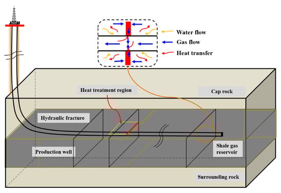
Figure 1.
Electrofrac technical sketch of shale-gas recovery based on hydraulic fracture heating (modified from Liu et al. []).
As a way of direct heating of hydraulic fractures, electromagnetic heating can be enhanced by hydrocarbons to increase shale gas and oil shale production with the help of nanoparticles. Thoram and Ehrig-Economides [] make the use of small-scale nuclear power plants to inject high-quality saturated steam and heat the SRV region to a specified temperature. Kerogen can be decomposed into oil and gas at this temperature.
In addition, for low temperature treatment, ExxonMobil conducted several months of low-temperature field experiments [] at its colonial mine in northwest Colorado. The data, including the temperature, voltage, current and rock deformation were obtained, analyzed and interpreted by Hoda et al. []. The above exploration provides a broad prospect for the application of heat treatment into unconventional resources.
Heat treatment technology can improve the shale oil and gas recovery rate [,,,,,]. During heating, kinetics of kerogen may undergo thermal decomposition []. In addition, micro-fractures connect, and large-scale tensile cracks develop with inorganic minerals expanding, thus improving the connectivity of fractures network []. However, the interaction mechanism of high-temperature, two-phase flow and shale deformation was still not studied in depth.
The research of the coupling mechanism between temperature and two-phase flow often appeared in energy mining engineering in the past, such as heating-enhanced coalbed methane recovery, heating-enhanced shale-gas recovery and geothermal exploitation. The thermal stimulation is achieved by injecting hot water [,,] and hot gas [,], which can be regarded as a beneficial auxiliary production technology to improve the coalbed methane and shale-gas recovery.
Wang et al. [], Salmachi and Haghighi [] confirmed that heating-enhanced gas recovery increased the cumulative gas production by 58% and 12%, respectively compared with conventional production. In the mining process of these different energy sources, the similar multi-field coupling effect exists—that is, the coexistence of temperature fields, seepage fields and fracture fields in rock reservoirs, forming a complex coupling effect between heat and gas–water two-phase flows.
Theoretical analysis and numerical simulations have been performed to study these coupling effects. The focus of these studies is to establish mathematical models of heat conduction and two-phase flow (e.g., Shang et al. []; Wang et al. []; Teng et al. []). Among them, two-phase flow models [], thermal-flow coupling models [,,], thermal-hydraulic-mechanical coupling models [,,] and thermal-two-phase fluid-solid coupling models have been proposed.
For example, Teng et al. [] proposed a thermal-hydraulic-mechanical (THM) fully coupled model to describe the complex coupling effects between geological mechanics, CBM flow and energy transfer. The heat and mass transfer characteristics of CBM recovery under thermal stimulation were quantitatively predicted using the THM model. However, this model only considers a single-phase flow.
Li et al. [] established a thermal-two-phase flow-mechanical coupling model for CBM exploitation with the influence of temperature and groundwater. Qiao et al. [] proposed a thermal-two-phase flow model of pore-scale based on the self-similar fractal scaling law through unsaturated shale. However, the two-phase flow is considered as immiscible.
Liu et al. [] proposed a numerical model to investigate the effect of hydraulic fracture heating on shale-gas recovery. Their results show that shale-gas recovery can be improved by increasing the temperature of hydraulic fractures. Zhu et al. [] numerically analyzed the application and effect of heat treatment in shale gas exploitation by a fully coupled model. The influence of related parameters on the effect of heat treatment was also analyzed. They suggested that heat treatment has a significant effect on long-term efficient shale production.
Liu et al. [] established a thermal-fluid–solid coupling numerical model in the background of simulated microwave heating, revealed the influence mechanism of gas thermal desorption and thermal cracking processes on matrix porosity evolution and evaluated the enhancement efficiency of microwave heating on shale-gas recovery. These studies ignored the heterogeneity of shale. Wu et al. [] established a new fractal theoretical model to predict single-phase and two-phase flow as well as heat and mass transfer in porous media.
The absolute and relative permeability, effective thermal conductivity under the interaction of two-phase flow and heat conduction in unsaturated porous media were analytically solved. However, these models did not fully cover the interaction mechanism among the thermal conduction and convection, the gas–water two-phase flow and the evolution of heterogeneous fracturing in the shale reservoir [].
In order to verify the applicability and effectiveness of heat treatment on shale-gas recovery, a fully coupled THGM model is established in this paper. The interactions of different mechanisms in the heterogeneous shale reservoir are considered, such as heat conduction and convection, deformation of the shale reservoir, gas desorption and two-phase flow. The heat-induced interactions are considered in shale reservoirs, including the heat-induced gas adsorption and fracturing.
The superiorities of the thermal stimulation are evaluated and compared with conventional reservoir treatment techniques through a shale-gas-drainage example. The results can provide an engineering application prospect of heat enhanced shale-gas recovery. This paper is organized as follows: In Section 2, the interaction mechanisms are discussed, and a coupled THGM model is proposed. In Section 3, the permeability test process of shale after 50 °C temperature treatment is conducted, and a numerical model for the coupled multi-physics process with shale microstructure is obtained to verify the experiment results. In Section 4, the stimulation effects of heat treatment on shale-gas recovery are quantified. The efficiency of shale-gas production after thermal stimulation is compared with that of conventional hydraulic fracturing. The findings and conclusions are presented in Section 5.
2. Governing Equation for the THGM Coupling Process
2.1. Shale Reservoir Deformation Considering Gas Adsorption and Thermal Expansion
The deformation field equation of the shale skeleton is composed of equilibrium equation, geometric equation and physical equation.
The force on the shale unit is balanced. The balance equation is
where is the total stress tensor, is the derivative of the tensor along the y direction, and is the tensor of the volume force.
According to the effective stress principle, there is a relationship between the total stress and effective stress as follows
where p stands for the pore pressure as
is the Biot coefficient, , where represents the compression coefficient of pores, and represents the compression coefficient of the shale skeleton. stands for the Kronecker function, .
Integrating Equation (2) into Equation (1) yields
Assuming that the coal unit body only produces small deformation in the process of coalbed methane mining, the following equation can be derived from the continuity of the deformation process
where is the strain tensor, and are the unit position shift of the and direction, respectively.
The shale skeleton is under elastic state in the process of heating-enhanced shale-gas recovery in general. Depending on the linear elastic assumptions, the total strain is the sum of strain of in-situ stress, gas pressure, water pressure, absorption expansion and thermal expansion. Therefore, the generalized Hoek law of the deformation can be applied. The constitutive equation is
where E is the elastic modulus of tension and compression, and is the shear elastic modulus, . is the elasticity modulus, is the Poisson’s ratio, is volumetric strain, is the Biot coefficient, is the volume modulus of the porous medium, , is the volume thermal coefficient of solid matrix, and is the temperature.
It is assumed that the deformation components caused by shale gas adsorption and thermal expansion are equal in three directions. Combining Equations (4) and (5) with Equation (6) yields the equilibrium equation of the deformed shale reservoir under the condition of heat injection
2.2. Permeability Evolution for Thermal Fracturing Process
For the classical matchstick block of fractured shale, the permeability is
where is the permeability, is the aperture of the fractures, and is the spacing of the fractures at the current state.
As shown in Figure 2, under external loading and temperature changes, new microfractures may initiate and expand. The aperture of the existing fractures may also change with the temperature. These two changes may significantly modify the permeability of the fractured shale.
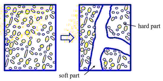
Figure 2.
Conceptual model for fracture evolution in fractured shale.
Thus, by dividing fractured shale into fractures (soft part) and matrix (hard part), with considering the compaction of fractured shales and generation of new fractures in the matrix, a permeability evolution model was established by Shang et al. to describe the fracturing process induced by changes in effective stress, temperature or both []. There are three parameters in this model: the proportion of fracture aperture in the fractures, the evolution of mean fracture aperture and the effect of temperature change and external loading on fracture density. It is expressed as
where is the initial permeability, and is the spacing of the fractures at the initial state. is the fracture aperture proportion of the soft parts in the fractured shale. is the increase of the mean effective stress, which is ; and are the current and initial effective stress, respectively. is the bulk modulus of the fractures.
2.3. Two-Phase Flow, including Adsorption and Dissolution
The continuity equation of fluid mainly represents the mass conservation. It is also the basic equation to describe the motion of matter. The subscripts and are the gas phase and water phase, respectively. Considering the adsorption of shale gas on a shale skeleton, the continuity equations of gas phase and water phase can be expressed as
For gas flow,
For water flow,
where , is the gas solubility in water, and , are the densities of water and gas under formation condition, respectively. , are the saturation of gas and water, respectively. is the porosity of shale. , are the fluid strength of gas and water, respectively.
The motion equation of gas–water coupled seepage is
where is the absolute permeability of shale, is the relative permeability of gas, is the viscosity of gas, is the gas pressure, is the relative permeability of water, is the viscosity of water, and is the water pressure.
Substituting Equation (12) into Equation (10) and Equation (13) into Equation (11) yield gas–water coupled equations for the shale reservoir, respectively.
2.4. Heat Conduction of Two-Phase Flow Considering Thermal Convection
Considering the effects of heat conduction and convection, it is assumed that shale reservoir and two-phase flow are always in a heat-balance state. Combined with gas–water two-phase flow motion equation, the governing equation of energy conservation in shale reservoir is
where is the specific heat capacity, is the temperature, is the effective heat conduction coefficient, is the volumetric modulus of gas, is the thermal expansion coefficient of gas, represents the volumetric modulus of water, is the thermal expansion coefficient of water, is the heat source, and , . Combining Equations (10) and (11) with (14) yields
2.5. Multiple Physical Field Coupling Model
The combination of Equations (7), (9), (12), (13) and (15) makes up the THGM full-field coupling mathematical model for heating-enhanced shale-gas recovery. As shown in Figure 3, this model covers a shale-reservoir-deformation field, gas–water coupled seepage field, temperature field and fracture field. With the temperature rise in the shale reservoir, the stress field change causes the desorption and migration of the adsorption state of shale gas. New fractures generate from the matrix, the original fractures close or expand at the same time, and the gas–water coupling seepage path changes. With the production of shale gas, the pore pressure reduces, reigniting the change in the stress field.
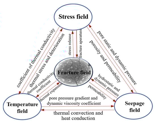
Figure 3.
Cross-couplings in heating-enhanced shale-gas recovery.
3. Modelling Results and Discussions
3.1. Permeability Test of Shale after 50 °C Temperature Treatment
To study the permeability of shale after 50 °C temperature treatment, a permeability test was conducted. First, the moisture content of the shale sample was tested, and the average moisture content was 0.0425%. The test results are shown in Table 1.

Table 1.
The basic physical parameters of shale samples under 50 °C temperature treatment.
As shown in Figure 4, three shale samples were heated at high temperature in the high-temperature furnace. The target temperature was 50 °C. Starting from room temperature, the heating rate was 5 °C/min. After reaching the target temperature, the temperature was maintained for two hours. Then, the samples were cooled to room temperature of 20 °C in a sealed container.
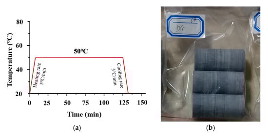
Figure 4.
Temperature treatment process of shale samples. (a) The heating path of the shale and (b) the shale samples after temperature treatment.
After the heat treatment of shale samples, the permeability test is conducted on the treated samples. The pulse attenuation permeability meter (PDP-200) of the key Laboratory of coal-bed methane resources and accumulation process of ministry of education of China University of Mining and Technology was used to test the permeability of Lushan shale, as shown in Figure 5. The gas used in this test is high pure N2 with a purity of 99.99%. The test was controlled by axial displacement, with a confining pressure of 2900psi, test pressure of 800 psi and nitrogen rate of 0.1 mm/min. Nitrogen seepage velocity test is performed synchronously at room temperature, the flowmeter accuracy is 0.0001 L/min, and the extensometer accuracy is 0.001 mm.
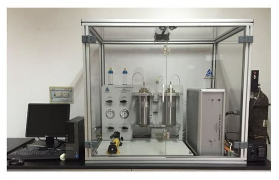
Figure 5.
Pulse decay permeameter.
The permeability data of shale samples under certain pore pressure and confining pressure based on the transient pulse experiment are shown in Table 2.
Table 2.
Moisture content of the shale samples at room temperature.
3.2. Establishment of the Numerical Model
In this section, the COMSOL multi-physics software platform is introduced to numerical analyze the multi-physical field coupling model, explore the influence mechanism among each physical field and predict the productivity of heating-enhanced shale-gas recovery. The THGM, a multi-physical field coupling model is used to analyze the internal temperature field, capillary pressure and gas–water saturation evolution mechanism of shale under the heating condition of 50 °C.
The corresponding permeability simulation was also conducted to verify the experiment results. The analysis of thermal stimulation enhanced shale-gas recovery is retained on the basis of theory and numerical research, and engineering practices have not been performed on the related fields. The following analysis is not a complete meaning of thermal stimulation enhanced shale-gas recovery but a related heat-gas–liquid-mechanical coupling process analysis.
Based on the established multi-field coupling model, the permeability evolution and gas–water coupled seepage process in shale can be simulated by simple model constraints, which can reflect the reliability of the full coupling model to a certain extent. The validity of the THGM coupling model established was tested by comparing with the shale permeability test results after the 50 °C temperature treatment.
A geometric model of 0.05 × 0.025 m rectangle (ABCD) was established to characterize the shale samples in numerical calculation (Figure 6). The matching operation between the microstructure image of shale samples and the rectangle (ABCD) was used to simulate the change in permeability and temperature conduction process in real shale. Given the confining pressure and test pressure, AC was a constant temperature boundary. The given temperature value was 50 °C. Gas–water two-phase flow existed in the shale sample.
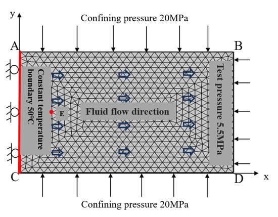
Figure 6.
Computational model for the control experiment.
The coordinate of observation point E (0.005 m, 0.0125 m) was used to observe the change in the two-phase flow with time. In the aspect of boundary conditions, for the temperature field, all boundaries in the model were set as adiabatic boundaries, on which the temperature was allowed to change. For the seepage field, there was no fluid flow at all boundaries. For the solid deformation field, normal phase displacement was constrained at the boundary of CA/DC. The simulation parameters used are shown in Table 3 and were mainly from the current research literature and related parameter tests of shale samples.
Table 3.
The model parameters in the calculations for a gas production process.
3.3. Evolution of Temperature Field
First, the temperature evolution path is obtained by numerical analysis. Figure 7 shows the shale reservoir temperature distribution at 0.5, 2, 8 and 10 min of heating, respectively. Due to the heterogeneity of the internal structure of shale, temperature changes also present a certain nonlinear variation relation with time. According to the analysis, the heat transfer mainly includes two forms: heat conduction and heat convection.
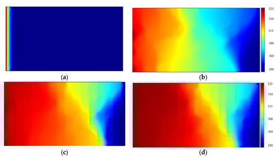
Figure 7.
The temperature distribution at different times. (a) 0.2 min; (b) 2 min; (c) 8 min; (d) 10 min.
Heat conduction and convection are coupled and affected by fluid seepage. The heat conduction is mainly controlled by the heat conduction coefficient, and the effect of heat transfer into shale along the constant temperature boundary is roughly the same. Due to the influence of the gas–liquid-mechanical coupling seepage, the heat transfer path is non-uniform and nonlinear. It can be observed from Figure 7 that the temperature change mainly occurs at the heat injection boundary and gradually spreads along the fluid flow direction.
After 10 min of heating, as shown in Figure 7d, the temperature of most internal structures of shale reached 50 °C. However, as with the temperature treatment test, after that, the shale sample was heated for 6 min at a speed of 5 °C/min, and the temperature was kept constant for 2 h to achieve uniform heating and reach the target temperature of the overall shale.
3.4. Capillary Pressure and Water Saturation of Shale
The gas saturation, water saturation and capillary pressure change constantly in the gas–water coupling seepage process. Figure 8 describes the evolution of water saturation and capillary pressure at observation point E (0.005 m, 0.0125 m). First, capillary pressure is the difference between gas pressure and water pressure. The capillary pressure is affected by the pore size distribution, permeability and many other factors in the process of gas–water coupled seepage.
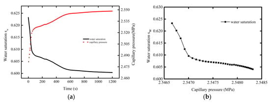
Figure 8.
Evolution curve of the water saturation and capillary pressure at observation point E (0.005 m, 0.0125 m). (a) The change in water saturation and (b) change in water saturation capillary pressure over time with capillary pressure.
As shown in Figure 8a, water saturation generally shows a decreasing trend with the time of heat injection. In the first 200 s, the water saturation rapidly drops from 0.625 to 0.607, then decreases slower and finally reaches 0.6 after temperature injection for 1200 s. To describe the internal heterogeneity of the shale fracture and matrix, the water saturation curve is not completely smooth. This is because shale gas desorption happens all the time in the process of physical fields coupled with temperature. The change in gas–water seepage leads to solid deformation, and solid deformation causes the pore pressure change.
Then, the change in pore pressure leads to the change in permeability. The capillary pressure changes during gas–water flow process in shale are analyzed below. As shown, the capillary pressure increases dramatically at first and then slowly with the time of heat injection. At 200 s, the capillary pressure increases to 2.528 MPa. At 1200 s, the capillary pressure rises slowly to 2.545 MPa. In addition, Figure 8b analyzes the variation of water saturation with the capillary pressure. The higher the capillary pressure is, the lower the water saturation will be. At this time, more adsorbed shale gas will be desorbed, part of dissolved gas will be converted into free gas, and the shale gas productivity will increase.
3.5. Permeability of Shale and Shale Gas Saturation Change
Figure 9 shows the permeability evolution process in shale samples. As shown, there is a large difference between the permeability of fractures in shale and matrix at the initial heating stage. The permeability of fracture is almost an order of magnitude multiple of that of the matrix.
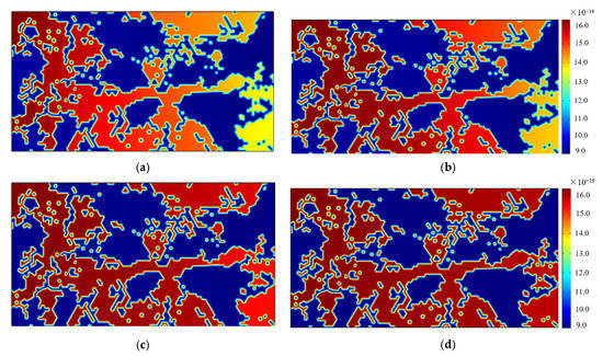
Figure 9.
Permeability variation characteristics at different times. (a) 0.2 min; (b) 2 min; (c) 5 min; (d) 10 min.
With the extension of the heating time, the fracture permeability still increases slowly along the direction of fluid flow. The permeability change of matrix is not shown in Figure 9. The reason is that the temperature, the confining pressure and test pressure are not sufficient to cause the initiation of matrix cracking in shale. The effect of temperature only causes the desorption of adsorbed shale gas, and a small part of the dissolved gas is converted into free gas, which leads to an increase in free gas in the seepage fractures and further leads to an increase in the overall permeability in the shale.
The observation shows that the permeability in the fracture changes with time. After about 10 min, the permeability in the fracture part almost reaches the same value, which is about 1.6 × 10⁻¹⁸ m2, while that in the matrix is about 9 × 10⁻¹⁹ m2. The specific permeability of shale depends on the proportion of the matrix to fracture. According to the permeability evolution model established in Section 2.2, the proportion of the fracture part in numerical simulation in this section is 32.3%, and the total permeability of shale can be calculated to be about 1.261 × 10⁻¹⁸ m2. The permeability value of the shale sample under the heating condition of 50 °C is 1.126 × 10⁻¹⁸ m2. The numerical calculation results are in good agreement with the test results.
Corresponding to the analysis of permeability changes in shale fractures caused by thermal desorption of shale gas in Figure 9, Figure 10 shows the evolution process of shale gas saturation with temperature. First, due to the heterogeneity of shale structure, the evolution curve of shale gas saturation shows an unstable growth trend with temperature. When the shale sample is heated, the activity of shale gas molecules enhances under the combined action of temperature and pressure, and shale gas desorption occurs.
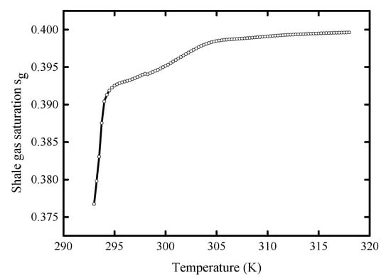
Figure 10.
Gas saturation evolution curve of observation point E (0.005 m, 0.0125 m) with temperature.
The capillary pressure between gas and water increases, and the gas saturation increases rapidly from 0.375 in the initial state to 0.393 at 2 min and then slowly to 0.4 at the time of 10 min. This is essentially consistent with the change trend of permeability, which also indicates that the free gas content in the fracture reflects the overall permeability of shale. In addition, it should be noted that the numerical simulation in this section is for the coupling mechanism of multi-physical fields in the heating process of a small-scale shale sample. The numerical variation of water saturation and permeability is small. This is a description of the variation trend of each physical field in the coupling process.
4. Production Capacity Analysis of Heat Injection in Enhanced Shale Gas Recovery
4.1. Numerical Model of Heating-Enhanced Shale Gas Recovery
In order to further validate the correctness of the established multi-field coupling model and the applicability in the heating-enhanced shale-gas recovery project, a simplified 2D model of shale gas reservoir is simulated in this section by using the multi-field coupling model. As shown in Figure 11, the shale gas extraction area is 10,000 square meters, and a square geometric physical model of 100 × 100 m is set up.
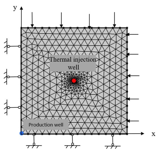
Figure 11.
Computation model of shale gas heat injection production.
The thickness of shale reservoir is 2 m, and the initial shale gas pressure is 3 MPa. The heat injection well is at the central coordinate of the model at the location of (50 m, 50 m), with a radius of 0.1 m. According to Teng’s model [], the heat injection temperature is 95 °C, and the extraction well is located at the location of (0 m, 0 m).
In terms of boundary conditions, for the temperature field, all boundaries in the model are set as adiabatic boundaries. The temperature is allowed to change at the adiabatic boundaries. For the seepage field, there is no fluid flow at all boundaries. For the solid deformation field, the normal displacement is constrained by the left boundary and lower boundary. The values of the other simulation parameters are listed in Table 3.
4.2. Analysis of Shale Gas Production Efficiency by Thermal Injection
The influence of thermal injection on cumulative shale-gas production is studied in this section. The cumulative shale-gas production is compared between conventional and heating-enhanced shale-gas recovery. Figure 12 shows the comparison of the gas production rates between the two methods. It can be seen that the shale-gas-production rate for both methods decreases slowly over a 10,000-day production cycle. On the 2000th day, the production rates of shale gas in both production methods declined to an inflection point.
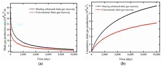
Figure 12.
Comparative analysis of gas production between heat injection and conventional exploitation of shale gas. (a) The shale-gas-production rate and (b) cumulative shale-gas-production rate.
The gas production rates of heating-enhanced and conventional production were 8269.19 and 5209.56 m3/d, respectively. They decreased to 20.49% and 20.17% of the initial production, respectively. After 2000 days, the shale-gas-production rate of heating-enhanced production drops more than that of conventional production. After 10,000 days of production, the shale production rates of the two production methods are almost the same. Similarly, as shown in Figure 12b, the cumulative production of shale gas shows a trend of first substantial increase and then a slow increase.
For example, after 8000 days of production, the cumulative shale-gas production from conventional production is 3.49 × 10⁷ m3, while the cumulative gas production from heating-enhanced shale-gas recovery increases to 5.55 × 10⁷ m3. As a whole, the shale-gas production yields an increase of 59.1% after 2.7 years, 58.8% after 9.9 years and 58.7% after 27.4 years. The cumulative production rates of shale gas at the 10,000th day under heating treatment and conventional treatment are 6.0 × 10⁸ and 3.8 × 10⁸ m3, respectively.
There is a difference of 2.2 × 10⁸ cubic meters in the shale-gas production between the two kinds of treatment. It is estimated that heat-treatment technology is helpful to bring an economic efficiency of 612 million in the whole production cycle. In summary, the simulation results show that heat treatment can significantly improve shale-gas production in the first half of the production cycle.
5. Conclusions
A THGM coupling model was proposed to describe the interactions of permeability evolution for the cracking process of the heterogeneous shale, the deformation of shale reservoirs affected by gas adsorption and thermal expansion and the heat conduction and convection as well as the gas–water two-phase flow in a heterogeneous shale reservoir.
Based on this coupling model, a numerical simulation was performed to represent the complexed coupling THGM mechanisms at shale sample grade under 50 °C. In addition, the interactions among the stress, high-temperature and two-phase flow in a heterogeneous shale reservoir were also studied. The influences of temperature on shale-gas production during the heat treatment of a shale reservoir were analyzed, and the effectiveness of heat-treatment-enhanced shale-gas recovery in prolonging production life was evaluated. Based on these studies, the following innovative conclusions were found:
First, heat injection leads to an increase in the capillary pressure and free gas content in the process of gas–water two-phase flow in shale reservoirs. The rise of temperature promotes the shale gas desorption and the separation of partially dissolved gas. The changing rate of two-phase flow causes the deformation of the shale reservoir. The mechanical deformation of the reservoir then leads to a change in the pore pressure and capillary pressure. At the same time, the changes in both the capillary pressure and the gas–water saturation present certain irregularities because of the heterogeneity of shale.
Secondly, the thermal stimulation resulted in a permeability increase in fractured shale. With the temperature increasing, the desorption of shale gas becomes faster, and more free gas flows into the fracture system, thereby, leading to a significant increase in the shale permeability.
Thirdly, the proposed THGM model well forecast the thermal stimulation for the shale gas reservoir. Heat-treatment technology can greatly enhance cumulative shale-gas production in the first half of the production cycle. Heat treatment changes the temperature of the shale reservoir, and the coupling THGM effects stimulate the mechanical deformation and shale-gas production. The numerical simulations revealed that the heat treatment enhanced cumulative gas production by 58.7% after 27.4 years.
Author Contributions
Conceptualization, Z.Z. and J.W.; methodology, W.Y.; software, X.S.; validation, X.S. and Z.Z.; data curation, X.S. and J.W.; writing—original draft preparation, X.S.; writing—review and editing, Z.Z.; visualization, X.S. and C.Z.; supervision, Z.Z.; revision, X.S.; funding acquisition, C.Z., X.S. and Z.Z. All authors have read and agreed to the published version of the manuscript.
Funding
This research was funded by the National Key R&D Program of China (Grant No. 2020YFA0711800), National Natural Science Foundation of China (Grant No. 42030810, 52204113), Natural Science Foundation of Jiangsu Province for Youth Foundation (Grant No. BK20220232) Open Foundation of Key Laboratory of Deep Earth Science and Engineering (Grant No. DESE 202205), and China Postdoctoral Science Foundation (Grant No. 2020M681772).
Institutional Review Board Statement
Not applicable.
Informed Consent Statement
Not applicable.
Data Availability Statement
Not applicable.
Conflicts of Interest
The authors declare no conflict of interest.
References
- Liu, Y.L.; Zheng, X.B.; Peng, X.F.; Zhang, Y.Y.; Chen, H.D.; He, J.H. Influence of natural fractures on propagation of hydraulic fractures in tight reservoirs during hydraulic fracturing. Mar. Petrol. Geol. 2022, 138, 105505. [Google Scholar] [CrossRef]
- Anderson, D.M.; Nobakht, M.; Moghadam, S.; Matter, L. Analysis of production data from fractured shale gas wells. In Proceedings of the 2010 SPE Shale Gas Production Conference, Pittsburgh, PA, USA, 23–25 February 2010. [Google Scholar]
- Zheng, S.P.; Lin, M.; Jiang, W.B.; Qiu, X.; Chen, Z. New method of in situ high-resolution experiments and analysis of fracture networks formed by hydraulic fracturing. J. Petrol. Sci. Eng. 2022, 217, 110849. [Google Scholar] [CrossRef]
- Shakib, J.T.; Akhgarian, E.; Ghaderi, A. The effect of hydraulic fracture characteristics on production rate in thermal EOR methods. Fuel 2014, 141, 226–235. [Google Scholar] [CrossRef]
- Du, X.W.; Carlson, K.H.; Tong, T.Z. The water footprint of hydraulic fracturing under different hydroclimate conditions in the Central and Western United States. Sci. Total Environ. 2022, 840, 156651. [Google Scholar] [CrossRef] [PubMed]
- Kookana, R.S.; Williams, M.; Gregg, A.; Semmler, A.; Du, J.; Apte, S.C. Sorption, degradation and microbial toxicity of chemicals associated with hydraulic fracturing fluid and produced water in soils. Environ. Pollut. 2022, 309, 119754. [Google Scholar] [CrossRef] [PubMed]
- Suo, Y.; Su, X.H.; Ye, Q.Y.; Chen, Z.X.; Feng, F.P.; Wang, X.Y.; Xie, K. The investigation of impact of temperature on mixed-mode fracture toughness of shale by semi-circular bend te.est. J. Petrol. Sci. Eng. 2022, 217, 110905. [Google Scholar] [CrossRef]
- Liu, Y.M.; Xue, L.F.; Bai, F.T.; Zhao, J.M.; Yan, Y.Y. Three-Dimensional Numerical Simulation of Hydrocarbon Production and Reservoir Deformation of Oil Shale In Situ Conversion Processing Using a Downhole Burner. ACS Omega 2022, 7, 23695–23707. [Google Scholar] [CrossRef]
- Pei, S.F.; Cui, G.D.; Zhang, L.; Zhang, P.F.; Huang, L.J.; Ren, S.R. Performance and important engineering aspects of air injection assisted in situ upgrading process for heavy oil recovery. J. Petrol. Sci. Eng. 2021, 202, 108554. [Google Scholar] [CrossRef]
- Symington, W. ExxonMobil’s electrofrac processTM for in situ oil shale conversion. In Proceedings of the 26th Oil Shale Symposium, Golden, CO, USA, 16–19 October 2006. [Google Scholar]
- Symington, W. Field testing of electrofrac™ process elements at ExxonMobil’s colony mine. In Proceedings of the 29th Oil Shale Symposium, Golden, CO, USA, 8–11 June 2009. [Google Scholar]
- Asghar, S.; Hassan, H.; Thomas, H.G. Thermal analysis of high frequency electromagnetic heating of lossy porous media. Chem. Eng. Sci. 2010, 172, 13–22. [Google Scholar]
- Liu, J.; Xie, H.P.; Li, M.H.; Li, C.B.; Gao, M.Z.; Shang, D.L.; Li, J.H. Effect of microwave radiation on mechanical behaviors of tight fine sandstone subjected to true triaxial stress. Int. J. Rock Mech. Min. 2022, 152, 105063. [Google Scholar] [CrossRef]
- Chen, T.Y.; Zheng, X.; Qiu, X.; Feng, X.T.; Elsworth, D.; Cui, G.L.; Jia, Z.H.; Pan, Z.J. Experimental study on the feasibility of microwave heating fracturing for enhanced shale gas recovery. J. Nat. Gas Sci. Eng. 2021, 94, 104073. [Google Scholar] [CrossRef]
- Yahya, N.B.; Kashif, M.; Nasir, N.; Akhtar, M.N.; Yusof, N.M. Cobalt ferrite nanoparticles: An innovative approach for enhanced oil recovery application. J. Nano Res. 2012, 17, 115–126. [Google Scholar] [CrossRef]
- Thoram, S.; Ehlig-Economides, C. Heat transfer applications for the stimulated reservoir volume (SRV). In Proceedings of the Unconventional Resources Technology Conference (URTeC) 2021, Sanantonio, Chile, 28 July 2021. [Google Scholar]
- Hoda, N.; Fang, C.; Lin, M.W.; Symington, W.A.; Stone, M.T. Numerical Modeling of ExxonMobil’s Electrofrac™ Field Experiment at Colony Mine. In Proceedings of the 30th Oil Shale Symposium, Golden, CO, USA, 18–20 October 2010. [Google Scholar]
- You, J.H.; Lee, K.J. The experimental investigation and data-driven modeling for thermal decomposition kinetics of Green River Shale. Fuel 2022, 320, 123899. [Google Scholar] [CrossRef]
- Ge, Z.L.; Sun, Q.; Gao, Q.; Li, D.L.; Zhang, Y.L.; Huang, H. Thermoacoustic emission characteristics and real-time damage evolution in shales of the Lower Palaeozoic Niutitang Formation. Int. J. Rock Mech. Min. 2022, 157, 105175. [Google Scholar] [CrossRef]
- Liu, J.; Wang, J.G.; Leung, C.F.; Gao, F. A fully coupled numerical model for microwave heating enhanced shale gas recovery. Energies 2018, 11, 1608. [Google Scholar] [CrossRef]
- Salmachi, A.; Haghighi, M. Feasibility study of thermally enhanced gas recovery of coal seam gas reservoirs using geothermal resources. Energy Fuel 2012, 26, 5048–5059. [Google Scholar] [CrossRef]
- Liu, H.; Pan, L.W.; Guo, Y.; Zhou, S.K.; Xiong, Q.; Dai, F.Q.; Pei, S.H.; Huang, J.N. Simulation investigation of the particle flow behavior in the gas full circulation oil shale retort. J. Petrol. Sci. Eng. 2022, 215, 110674. [Google Scholar] [CrossRef]
- Zhou, F.; Hussain, F.; Cinar, Y. Injecting pure N2 and CO2 to coal for enhanced coalbed methane: Experimental observations and numerical simulation. Int. J. Coal Geol. 2013, 116, 53–62. [Google Scholar] [CrossRef]
- Wang, H.Y.; Merry, H.; Amorer, G.; Kong, B. Enhance Hydraulic Fractured Coalbed Methane Recovery by Thermal Stimulation. Paper Presented at the SPE Unconventional Conference, Calgary, AB, Canada, 20–22 October 2015. [Google Scholar]
- Shang, X.J.; Wang, J.G.; Zhang, Z.Z. Analytical solutions of fractal-hydro-thermal model for two-phase flow in thermal stimulation enhanced coalbed methane recovery. Therm. Sci. 2019, 23, 1345–1353. [Google Scholar] [CrossRef]
- Wang, H.; Ajao, O.; Economides, M.J. Conceptual study of thermal stimulation in shale gas formations. J. Nat. Gas Sci. Eng. 2014, 21, 874–885. [Google Scholar] [CrossRef]
- Teng, T.; Zhao, Y.X.; Gao, F. A fully coupled thermo-hydro-mechanical model for heat and gas transfer in thermal stimulation enhanced coal seam gas recovery. Int. J. Heat Mass Transf. 2018, 125, 866–875. [Google Scholar] [CrossRef]
- Wang, J.G.; Peng, Y. Numerical modeling for the combined effects of two-phase flow, Deformation, gas diffusion and CO2 sorption on caprock sealing efficiency. J. Geochem. Explor. 2014, 144, 154–167. [Google Scholar] [CrossRef]
- Teng, T.; Wang, J.G.; Gao, F.; Ju, Y.; Jiang, C.B. A thermally sensitive permeability model for coal-gas interactions including thermal fracturing and volatilization. J. Nat. Gas Sci. Eng. 2016, 32, 319–333. [Google Scholar] [CrossRef]
- Qiao, X.W.; Shen, Y.Q.; Tan, X.H.; Qiu, S.X.; Jiang, Z.T.; Sasmito, A.P.; Xu, P. The Correlation between fluid flow and heat transfer of unsaturated shale reservoir based on fractal geometry. Fractals 2022, 30, 2250069. [Google Scholar] [CrossRef]
- Wu, C.Q.; Xu, H.J.; Zhao, C.Y. A new fractal model on fluid flow/heat/mass transport in complex porous structures. Int. J. Heat Mass Transf. 2022, 195, 123208. [Google Scholar] [CrossRef]
- Taron, J.; Elsworth, D. Thermal-hydrologic-mechanical-chemical processes in the evolution of engineered geothermal reservoirs. Int. J. Rock Mech. Min. 2009, 46, 855–864. [Google Scholar] [CrossRef]
- Noorishad, J.; Tsang, C.F.; Witherspoon, P.A. Coupled thermal-hydraulic-mechanical phenomena in saturated fractured porous rocks: Numerical approach. J. Geophys. Res. -Solid Earth 1984, 89, 10365–10373. [Google Scholar] [CrossRef]
- Li, S.; Fan, C.J.; Han, J. A fully coupled thermal-hydraulic-mechanical model with two-phase flow for coalbed methane extraction. J. Nat. Gas Sci. Eng. 2016, 33, 324–336. [Google Scholar] [CrossRef]
- Liu, J.; Liang, X.; Xue, Y.; Yao, K.; Fu, Y. Numerical evaluation on multiphase flow and heat transfer during thermal stimulation enhanced shale gas recovery. Appl. Therm. Eng. 2020, 178, 115554. [Google Scholar] [CrossRef]
- Zhu, G.P.; Yao, J.; Sun, H.; Min, Z.; Lu, T. The numerical simulation of thermal recovery based on hydraulic fracture heating technology in shale gas reservoir. J. Nat. Gas Sci. Eng. 2016, 28, 305–316. [Google Scholar] [CrossRef]
- Ahmadi, M.; Arash, D. Impact of thermally reactivated micro-natural fractures on well productivity in shale reservoirs, a numerical study. J. Nat. Gas Sci. Eng. 2016, 35, 583–592. [Google Scholar] [CrossRef]
- Shang, X.J.; Wang, J.G.; Zhang, Z.Z.; Gao, F. A three-parameter permeability model for the cracking process of fractured rocks under temperature change and external loading. Int. J. Rock Mech. Min. 2019, 123, 104106. [Google Scholar] [CrossRef]
Publisher’s Note: MDPI stays neutral with regard to jurisdictional claims in published maps and institutional affiliations. |
© 2022 by the authors. Licensee MDPI, Basel, Switzerland. This article is an open access article distributed under the terms and conditions of the Creative Commons Attribution (CC BY) license (https://creativecommons.org/licenses/by/4.0/).